EP3919987B1 - Uhr mit stossdämpfungsmechanismus - Google Patents
Uhr mit stossdämpfungsmechanismus Download PDFInfo
- Publication number
- EP3919987B1 EP3919987B1 EP20177877.6A EP20177877A EP3919987B1 EP 3919987 B1 EP3919987 B1 EP 3919987B1 EP 20177877 A EP20177877 A EP 20177877A EP 3919987 B1 EP3919987 B1 EP 3919987B1
- Authority
- EP
- European Patent Office
- Prior art keywords
- organ
- crown
- driven
- driving
- watch according
- Prior art date
- Legal status (The legal status is an assumption and is not a legal conclusion. Google has not performed a legal analysis and makes no representation as to the accuracy of the status listed.)
- Active
Links
Images

Classifications
-
- G—PHYSICS
- G04—HOROLOGY
- G04B—MECHANICALLY-DRIVEN CLOCKS OR WATCHES; MECHANICAL PARTS OF CLOCKS OR WATCHES IN GENERAL; TIME PIECES USING THE POSITION OF THE SUN, MOON OR STARS
- G04B37/00—Cases
- G04B37/04—Mounting the clockwork in the case; Shock absorbing mountings
-
- G—PHYSICS
- G04—HOROLOGY
- G04B—MECHANICALLY-DRIVEN CLOCKS OR WATCHES; MECHANICAL PARTS OF CLOCKS OR WATCHES IN GENERAL; TIME PIECES USING THE POSITION OF THE SUN, MOON OR STARS
- G04B3/00—Normal winding of clockworks by hand or mechanically; Winding up several mainsprings or driving weights simultaneously
- G04B3/04—Rigidly-mounted keys, knobs or crowns
- G04B3/041—Construction of crowns for rotating movement; connection with the winding stem; winding stems
-
- G—PHYSICS
- G04—HOROLOGY
- G04B—MECHANICALLY-DRIVEN CLOCKS OR WATCHES; MECHANICAL PARTS OF CLOCKS OR WATCHES IN GENERAL; TIME PIECES USING THE POSITION OF THE SUN, MOON OR STARS
- G04B3/00—Normal winding of clockworks by hand or mechanically; Winding up several mainsprings or driving weights simultaneously
- G04B3/04—Rigidly-mounted keys, knobs or crowns
- G04B3/046—Operation by rotation and axial movement with extra function of axial shift of operating element, e.g. crown combined with push button
-
- G—PHYSICS
- G04—HOROLOGY
- G04B—MECHANICALLY-DRIVEN CLOCKS OR WATCHES; MECHANICAL PARTS OF CLOCKS OR WATCHES IN GENERAL; TIME PIECES USING THE POSITION OF THE SUN, MOON OR STARS
- G04B3/00—Normal winding of clockworks by hand or mechanically; Winding up several mainsprings or driving weights simultaneously
- G04B3/04—Rigidly-mounted keys, knobs or crowns
- G04B3/043—Locking of the operating element, also by mounting in a concealed place
-
- G—PHYSICS
- G04—HOROLOGY
- G04B—MECHANICALLY-DRIVEN CLOCKS OR WATCHES; MECHANICAL PARTS OF CLOCKS OR WATCHES IN GENERAL; TIME PIECES USING THE POSITION OF THE SUN, MOON OR STARS
- G04B37/00—Cases
- G04B37/04—Mounting the clockwork in the case; Shock absorbing mountings
- G04B37/0409—Fixed mounting relating to wall clocks and pendulums
- G04B37/0418—Fixed mounting relating to wall clocks and pendulums with shock damping means
-
- G—PHYSICS
- G04—HOROLOGY
- G04B—MECHANICALLY-DRIVEN CLOCKS OR WATCHES; MECHANICAL PARTS OF CLOCKS OR WATCHES IN GENERAL; TIME PIECES USING THE POSITION OF THE SUN, MOON OR STARS
- G04B37/00—Cases
- G04B37/08—Hermetic sealing of openings, joints, passages or slits
- G04B37/10—Hermetic sealing of openings, joints, passages or slits of winding stems
-
- G—PHYSICS
- G04—HOROLOGY
- G04B—MECHANICALLY-DRIVEN CLOCKS OR WATCHES; MECHANICAL PARTS OF CLOCKS OR WATCHES IN GENERAL; TIME PIECES USING THE POSITION OF THE SUN, MOON OR STARS
- G04B43/00—Protecting clockworks by shields or other means against external influences, e.g. magnetic fields
- G04B43/002—Component shock protection arrangements
Definitions
- the present invention relates to a watch comprising an anti-shock device for a watch movement and more particularly, a disengageable crown allowing said watch movement to be released in the six degrees of freedom.
- the watch movement is subjected to repeated shocks when a watch is worn. These shocks disrupt the operation of the watch movement, which can increase its inaccuracy and result in a delay of several seconds.
- the document JP 6146699B2 discloses a crown for a watch movement suitable for integration into a timepiece equipped with a shock-resistant device.
- the crown is configured to occupy a first position in which the head of the stem is not in contact with the stem, the watch movement being disengaged from the crown.
- the crown is also configured to occupy the second position in which the head is embedded in the stem of the crown. In this position, the watch movement is therefore secured to the crown.
- the document EP3492995A1 discloses a crown system for a timepiece comprising a tube arranged to be fixed in a caseband of a timepiece and comprising a thread intended to be accessible from the outside of the caseband, a crown comprising a skirt provided with a thread arranged to cooperate with the thread, and a tubular central part arranged to be able to slide inside the tube, a stem intended to be in kinematic connection with a mechanism of the timepiece, one end of the stem being located inside the part tubular power plant, a clutch arranged to move between a disengaged state in which the rod and the crown are disengaged from each other, and an engaged state in which the rod and the crown are rotationally integral.
- the document WO2018/215491A1 describes a watch that has a shock-absorbing device that allows the movement to move in all directions. This watch also has a crown whose stem has a flexible coupling.
- the present invention aims to resolve all or part of the drawbacks mentioned above.
- the crown allows said watch movement to be released in the six degrees of freedom so that during an impact, said watch movement can move in the case without being linked to the case.
- the first position of the crown is a position disengaged in which a driving member is distant from a driven member and the second position is a engaged position in which the driving member is in contact with the driven member.
- said crown can engage or disengage said at least one driven member and said at least one driving member.
- said crown comprises an enclosure; said enclosure comprises said at least one driven member and/or said at least one driving member.
- said enclosure surrounds said at least one driven member and/or said at least one drive member, and/or said at least one driven member surrounds said at least one drive member.
- said enclosure can enclose said at least one driven member and said at least one driving member.
- said at least one driven member comprises a head configured to provide a grip to said at least one drive member.
- said head comprises a contact surface configured to provide a grip to said at least one drive member when said at least one driven member is in contact with said at least one drive member, and/or a guide surface configured to guide said at least one drive member, preferably, towards said contact surface.
- said at least one driven member may be driven by said at least one drive member when said crown is in said second position, preferably in said engaged position.
- said at least one drive member being configured to be distant from said contact surface when said crown is in said first position and/or said at least one drive member being configured to be in contact with said contact surface when said crown is in said second position.
- said at least one drive member and said contact surface cooperate when said crown is in said second position.
- said at least one drive member has a cylindrical shape configured to be engaged with said at least one driven member.
- said cylindrical shape of said at least one drive member constitutes a female correspondence of said head of said at least one driven member.
- said crown comprises at least one first seal and at least one protective member; said at least one first seal being arranged between said crown and at least one protective member.
- said at least one first seal is configured to seal the space between said crown and said at least one protective member.
- said at least one protection member is arranged between said crown and said at least one drive member.
- said at least one first seal is always in contact with said crown and said at least one protective member.
- said crown comprises at least one second seal configured to be in contact with said crown and/or said at least one protective member when said crown is in said first position and to be distant from said crown and/or said at least one protective member when said crown is in said second position.
- said at least one first seal is configured to seal the space between said crown and said at least one protective member up to 30 bars, in particular up to 10 bars, preferably up to 5 bars.
- said crown is waterproof while allowing freedom of movement of said watch movement.
- said at least one driven member is an end piece configured to be arranged on a stem of said watch movement or said at least one driven member is secured to a stem of said watch movement.
- said tip comprises a contact surface configured to provide a grip to said at least one drive member when said at least one driven member is in contact with said at least one drive member, and/or a guide surface configured to guide said at least one drive member, preferably, towards said contact surface.
- said crown can be arranged on said watch movement.
- said crown comprises at least one return member configured to move said at least one drive member between said first position and said second position.
- said at least one return member is arranged between said at least one driven member and said at least one drive member.
- said at least one return member is at least one spring.
- said at least one driven member can be distanced from said at least one drive member.
- said watch movement comprises a stem; said at least one driven member is in one piece with said stem of said watch movement.
- said crown can be integrated onto said stem of said watch movement during the assembly of said watch movement and/or during the manufacture of said stem.
- said crown can engage or disengage said at least one driven member and said at least one drive member, and said watch movement can move according to the 6 degrees of freedom without being hindered and be damped by said at least one damping element.
- said stem is a winding stem.
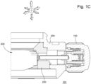
- FIG. 1A presents an anti-shock device 200 configured to allow the movement of a watch movement 210 according to at least three degrees of freedom, preferably according to six degrees of freedom.
- Said anti-shock device 200 comprises said watch movement 210, a crown 100 connected by a stem 220, preferably a winding stem 220, to said watch movement 210 and a caseband 250.
- said at least one damping element 230 can dampen the shocks of said watch movement 210 when said crown 100 is in contact or close to said caseband 250, because said watch movement 210 can move according to the 6 degrees of freedom without being hindered but while being damped by said at least one damping element 230.
- said crown 100 may comprise at least one drive member 120 and at least one driven member 110 configured to be driven and to be connected to said watch movement 210 by said stem 220.
- Said crown 100 also comprises an enclosure 105 configured to receive said at least one driven member 110 and/or said at least one drive member 120. More precisely, said enclosure 105 surrounds said at least one drive member 120, which in turn surrounds said at least one driven member 110 so that said enclosure 105 encloses said at least one driven member 110 and said at least one drive member 120.
- At least one drive member 120 When said at least one drive member 120 is placed or is located in said enclosure 105 of said crown 100, there is a space in which at least one protection member 130, preferably a tube 130, can be inserted or inserted. In other words, said at least one protection member 130 is arranged between said crown 100 and said at least one drive member 120.
- said crown 100 comprises at least one first seal 131 and at least one second seal 132.
- Said at least a first seal 131 may be arranged between said crown 100 and said at least one protection member 130, in other words, said at least one first seal 131 is configured to seal the space between said crown 100 and said at least one protection member 130.
- said at least one first seal 131 may always be in contact with said crown 100 and said at least one protective member 130, and may be configured to seal said space up to 30 bars, in particular up to 10 bars, preferably up to 5 bars.
- said crown 100 is configured to move between a first position 101 and a second position 102, more particularly and given that said at least one drive member 120 is integral with said crown 100, it is said at least one drive member 120 which is configured to move between a first position 101 and a second position 102.
- said watch movement 210 is free according to at least three degrees of freedom, preferably according to six degrees of freedom, Figures 1A And 1C , and its movements, or even its impacts with said caseband 250, are totally or partially damped by said at least one damping element 230 covering all or part of said caseband 250.
- said at least one drive member 120 is distant from said at least one driven member 110, but said crown 100 may be in contact or close to said caseband 250 and/or said at least one protection member 130.
- said at least one protection member 130 preferably said tube 130 is in contact with said crown 100 via at least one second seal 132.
- said at least one protection member 130 can be in contact with said at least one second seal 132 when said at least one drive member 120 is distant from said at least one driven member 110.
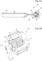
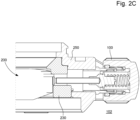
- said crown 100 When the user wishes to wind his watch, said crown 100 is moved to said second position 102, that is to say that said crown 100 is moved away from said caseband 250, and said watch movement 210 becomes integral with said crown 100, Figure 2C . Simultaneously, said at least one second seal 132 is moved away, by means of said crown 100, from said at least one protection member 130, Figure 2B .
- This movement from said first position 101 to said second position 102 can be facilitated by at least one return member 115, which can take the form of at least one spring 115, included between said crown 100, preferably said at least one drive member 120, and said at least one driven member 110, so as to distance said crown 100 from said caseband 250 but to bring said at least one driven member 110 and said at least one drive member 120 into contact, Figure 2B .
- at least one return member 115 can take the form of at least one spring 115, included between said crown 100, preferably said at least one drive member 120, and said at least one driven member 110, so as to distance said crown 100 from said caseband 250 but to bring said at least one driven member 110 and said at least one drive member 120 into contact, Figure 2B .
- Said at least one driven member 110 which may take the form of a tenon 110 or an end piece 113, may comprise a head 113 configured to provide a grip for said at least one drive member 120. Furthermore, according to the embodiments, said head 113 of said at least one driven member 110 may be in one piece, or integral, with said stem 220 of said watch movement 210 or, in the form of said end piece 113, may fit onto the stem 220.
- said head 113 comprises a contact surface 112 and a guide surface 111 configured to guide said at least one drive member 120 towards said contact surface 112, when said drive member 120 moves from said first position 101 towards said second position 102, also called clutch position 102.
- This cooperation or this driving of said at least one driven member 110 by said at least one driving member 120 can be allowed or permitted by the cylindrical shape of said at least one driving member 120 which surrounds said at least one driven member 110 and more particularly, by the grip offered by said contact surface 112 to said at least one driving member 120. More precisely, said cylindrical shape of said at least one driving member 120 constitutes a female correspondence of said head 113 of said at least one driven member 110, so that a complementarity between said at least one driving member 120 and said at least one driven member 110 is possible, in the manner of a socket wrench and a hexagonal bolt for example.
Landscapes
- Physics & Mathematics (AREA)
- General Physics & Mathematics (AREA)
- Electric Clocks (AREA)
- Vibration Dampers (AREA)
- Shafts, Cranks, Connecting Bars, And Related Bearings (AREA)
- Transmission Devices (AREA)
- Electromechanical Clocks (AREA)
Claims (13)
- Uhr, die einen Mittelteil (250), der so eingerichtet ist, dass er eine Uhrwerk (210) aufnimmt, sowie eine stoßdämpfende Vorrichtung (200) umfasst, die so eingerichtet ist, dass sie die Bewegung des Uhrwerks (210) in mindestens drei Freiheitsgraden ermöglicht; wobei die stoßdämpfende Vorrichtung (200) auch eine Krone (100) umfasst, die so eingerichtet ist, dass sie sich zwischen einer ersten Position (101), in der das Uhrwerk (210) in mindestens drei Freiheitsgraden frei ist, und einer zweiten Position (102) bewegt, in der das Uhrwerk (210) fest mit der Krone (100) verbunden ist, wobei die Krone (100) mindestens Folgendes umfasst:- ein angetriebenes Organ (110), das so eingerichtet ist, dass es angetrieben wird und mit dem Uhrwerk (210) verbunden ist, und- ein Antriebsorgan (120), das so eingerichtet ist, dass es von dem mindestens einen angetriebenen Organ (110) entfernt ist, wenn sich die Krone (100) in der ersten Position (101) befindet, und dass es mit dem mindestens einen angetriebenen Organ (110) in Kontakt steht, wenn sich die Krone (100) in der zweiten Position (102) befindet, wobei der Mittelteil (250) auch ein Dämpfungsorgan (230) umfasst, das so eingerichtet ist, dass es die Stöße des Uhrwerks (210) dämpft.
- Uhr nach Anspruch 1, die ein Gehäuse (105) umfasst, das mindestens ein angetriebenes Organ (110) und/oder mindestens ein Antriebsorgan (120) enthält.
- Uhr nach Anspruch 2, wobei das Gehäuse (105) das mindestens eine angetriebene Organ (110) und/oder das mindestens eine Antriebsorgan (120) umgibt und/oder das mindestens eine angetriebene Organ (110) das mindestens eine Antriebsorgan (120) umgibt.
- Uhr nach einem der Ansprüche 1 bis 3, wobei das mindestens eine angetriebene Organ (110) einen Kopf (113) umfasst, der so eingerichtet ist, dass er dem mindestens einen Antriebsorgan (120) einen Eingriff bietet.
- Uhr nach Anspruch 4, wobei der Kopf (113) eine Kontaktfläche (112), die so eingerichtet ist, dass sie dem mindestens einen Antriebsorgan (120) einen Eingriff bietet, wenn das mindestens eine angetriebene Organ (110) mit dem mindestens einen Antriebsorgan (120) in Kontakt steht, und/oder eine Führungsfläche (111) umfasst, die so eingerichtet ist, dass sie das mindestens eine Antriebsorgan (120) vorzugsweise in Richtung der Kontaktfläche (112) führt.
- Uhr nach Anspruch 5, wobei das mindestens eine Antriebsorgan (120) so eingerichtet ist, dass es von der Kontaktfläche (112) entfernt ist, wenn sich die Krone (100) in der ersten Position (101) befindet, und/oder das mindestens eine Antriebsorgan (120) so eingerichtet ist, dass es mit der Kontaktfläche (112) in Kontakt steht, wenn sich die Krone (100) in der zweiten Position (102) befindet.
- Uhr nach einem der Ansprüche 3 bis 6, wobei das mindestens eine Antriebsorgan (120) eine zylindrische Form aufweist, die so eingerichtet ist, dass sie in Eingriff mit dem mindestens einen angetriebenen Organ (110) steht.
- Uhr nach Anspruch 7, wenn sie mindestens von Anspruch 4 abhängt, wobei die zylindrische Form des mindestens einen Antriebsorgans (120) eine weibliche Übereinstimmung des Kopfes (113) des mindestens einen angetriebenen Organs (110) darstellt.
- Uhr nach einem der Ansprüche 1 bis 8, die mindestens eine erste Dichtung (131) und mindestens ein Schutzorgan (130) umfasst, wobei die mindestens eine erste Dichtung (131) zwischen der Krone (100) und dem mindestens einen Schutzorgan (130) angeordnet ist.
- Uhr nach Anspruch 9, wobei die mindestens eine erste Dichtung (131) so eingerichtet ist, dass sie den Raum zwischen der Krone (100) und dem mindestens einen Schutzorgan (130) abdichtet.
- Uhr nach einem der Ansprüche 1 bis 10, wobei das mindestens eine angetriebene Organ (110) ein Endstück (110) ist, das so eingerichtet ist, dass es auf eine Welle (220) des Uhrwerks (210) angeordnet ist, oder das mindestens eine angetriebene Organ (110) fest mit einer Welle (220) des Uhrwerks (210) verbunden ist.
- Uhr nach einem der Ansprüche 1 bis 11, die mindestens ein Rückstellorgan (115) umfasst, das so eingerichtet ist, dass es das mindestens eine Antriebsorgan (120) zwischen der ersten Position (101) und der zweiten Position (102) bewegt.
- Uhr nach einem der Ansprüche 1 bis 12, wobei die Welle (220) eine Aufzugswelle ist.
Priority Applications (5)
| Application Number | Priority Date | Filing Date | Title |
|---|---|---|---|
| EP20177877.6A EP3919987B1 (de) | 2020-06-02 | 2020-06-02 | Uhr mit stossdämpfungsmechanismus |
| US17/317,029 US11740588B2 (en) | 2020-06-02 | 2021-05-11 | Disconnectable crown |
| JP2021083091A JP7364621B2 (ja) | 2020-06-02 | 2021-05-17 | 接続解除可能なリュウズ |
| KR1020210068485A KR102636181B1 (ko) | 2020-06-02 | 2021-05-27 | 분리가능한 크라운 |
| CN202110589798.8A CN113759689A (zh) | 2020-06-02 | 2021-05-28 | 可脱开表冠 |
Applications Claiming Priority (1)
| Application Number | Priority Date | Filing Date | Title |
|---|---|---|---|
| EP20177877.6A EP3919987B1 (de) | 2020-06-02 | 2020-06-02 | Uhr mit stossdämpfungsmechanismus |
Publications (2)
| Publication Number | Publication Date |
|---|---|
| EP3919987A1 EP3919987A1 (de) | 2021-12-08 |
| EP3919987B1 true EP3919987B1 (de) | 2025-04-30 |
Family
ID=70975817
Family Applications (1)
| Application Number | Title | Priority Date | Filing Date |
|---|---|---|---|
| EP20177877.6A Active EP3919987B1 (de) | 2020-06-02 | 2020-06-02 | Uhr mit stossdämpfungsmechanismus |
Country Status (5)
| Country | Link |
|---|---|
| US (1) | US11740588B2 (de) |
| EP (1) | EP3919987B1 (de) |
| JP (1) | JP7364621B2 (de) |
| KR (1) | KR102636181B1 (de) |
| CN (1) | CN113759689A (de) |
Citations (3)
| Publication number | Priority date | Publication date | Assignee | Title |
|---|---|---|---|---|
| CH713666A1 (it) * | 2017-04-03 | 2018-10-15 | Maura Wasescha Gentilini | Orologio con sistema di sospensione antivibrazione del movimento. |
| WO2018215491A1 (en) * | 2017-05-22 | 2018-11-29 | Timelink Ag | Movement holder for a movement of a watch |
| CH714355A2 (it) * | 2017-11-20 | 2019-05-31 | Maura Wasescha Gentilini | Cassa per orologio da polso con sezione oscillante. |
Family Cites Families (17)
| Publication number | Priority date | Publication date | Assignee | Title |
|---|---|---|---|---|
| GB721920A (en) | 1952-07-17 | 1955-01-12 | Charles Jules Juillerat | Waterproof shock-absorbing watch case |
| JPS5455264A (en) | 1977-10-11 | 1979-05-02 | Aisin Warner | Automatic transmission |
| JPH01180688U (de) * | 1988-05-30 | 1989-12-26 | ||
| JP3602189B2 (ja) * | 1995-03-10 | 2004-12-15 | シチズン時計株式会社 | ネジロックリューズ構造 |
| EP1168113A1 (de) * | 2000-06-20 | 2002-01-02 | The Swatch Group Management Services AG | Vorrichtung zum Umschalten zwischen wenigstens drei verschiedene elektrischen Kontakten |
| WO2005040942A1 (fr) * | 2003-10-24 | 2005-05-06 | Richemont International Sa | Dispositif de commande à couronne débrayable pour montre |
| JP2010243343A (ja) | 2009-04-07 | 2010-10-28 | Seiko Epson Corp | 時計 |
| FR2956755B1 (fr) * | 2010-02-25 | 2012-08-17 | Cheval Freres Sas | Couronne de remontoir de montre multifonctions |
| JP5324509B2 (ja) * | 2010-03-26 | 2013-10-23 | セイコーインスツル株式会社 | 携帯時計 |
| FR2981467B1 (fr) | 2011-10-14 | 2014-04-18 | Xavier Bich | Montre et ensemble d'un dispositif antichoc et d'un casier de protection pour montre |
| FR2987684B1 (fr) * | 2012-03-01 | 2014-03-14 | Cheval Freres | Ensemble de couronne de commande d'une lunette indicatrice tournante, dite "rehaut", et montre le comportant |
| JP6146699B2 (ja) * | 2013-09-27 | 2017-06-14 | カシオ計算機株式会社 | スイッチ装置および時計 |
| JP6367059B2 (ja) * | 2014-09-09 | 2018-08-01 | セイコーインスツル株式会社 | 時計 |
| EP3279745B1 (de) | 2016-08-02 | 2023-06-14 | Meco S.A. | Ausrichtbare geschraubte krone |
| JP6829116B2 (ja) * | 2017-03-13 | 2021-02-10 | セイコーインスツル株式会社 | りゅうずロック機構付き時計 |
| CN110753884B (zh) * | 2017-04-18 | 2022-06-03 | 天美时集团美国股份有限公司 | 表冠推动器组件和包括该组件的手腕佩戴式电子设备 |
| CH714381A2 (fr) * | 2017-11-30 | 2019-05-31 | Ball Watch Company Sa | Système de couronne vissable pour pièce d'horlogerie. |
-
2020
- 2020-06-02 EP EP20177877.6A patent/EP3919987B1/de active Active
-
2021
- 2021-05-11 US US17/317,029 patent/US11740588B2/en active Active
- 2021-05-17 JP JP2021083091A patent/JP7364621B2/ja active Active
- 2021-05-27 KR KR1020210068485A patent/KR102636181B1/ko active Active
- 2021-05-28 CN CN202110589798.8A patent/CN113759689A/zh active Pending
Patent Citations (3)
| Publication number | Priority date | Publication date | Assignee | Title |
|---|---|---|---|---|
| CH713666A1 (it) * | 2017-04-03 | 2018-10-15 | Maura Wasescha Gentilini | Orologio con sistema di sospensione antivibrazione del movimento. |
| WO2018215491A1 (en) * | 2017-05-22 | 2018-11-29 | Timelink Ag | Movement holder for a movement of a watch |
| CH714355A2 (it) * | 2017-11-20 | 2019-05-31 | Maura Wasescha Gentilini | Cassa per orologio da polso con sezione oscillante. |
Also Published As
| Publication number | Publication date |
|---|---|
| CN113759689A (zh) | 2021-12-07 |
| EP3919987A1 (de) | 2021-12-08 |
| KR102636181B1 (ko) | 2024-02-13 |
| US11740588B2 (en) | 2023-08-29 |
| JP2021189177A (ja) | 2021-12-13 |
| JP7364621B2 (ja) | 2023-10-18 |
| US20210373494A1 (en) | 2021-12-02 |
| KR20210150291A (ko) | 2021-12-10 |
Similar Documents
| Publication | Publication Date | Title |
|---|---|---|
| EP3451071B1 (de) | Vorrichtung mit drucktaste für uhr | |
| FR2573303A1 (fr) | Mandrin a levier pour piece a main dentaire | |
| CH705043A2 (fr) | Pièce d'horlogerie portable incluant un bouton-poussoir. | |
| CH714365A2 (fr) | Mobile d'horlogerie à roue unidirectionnelle. | |
| WO2011104480A1 (fr) | Couronne de remontoir de montre multifonctions | |
| EP3825778B1 (de) | Steuerkranz für uhr | |
| EP3919987B1 (de) | Uhr mit stossdämpfungsmechanismus | |
| EP3697195B1 (de) | Getriebegehäuse und radfahrzeug mit einem solchen gehäuse | |
| CH717488A2 (fr) | Couronne débrayable pour un dispositif antichoc. | |
| EP2367075B1 (de) | Aufzugskrone für Uhren | |
| EP3697194B1 (de) | Getriebe und radfahrzeug mit einem solchen getriebe | |
| EP1975749B1 (de) | Uhr mit elastisch gehaltenem Uhrwerk | |
| EP2639656B1 (de) | Vorrichtung zur Betätigung einer Taucheruhr | |
| EP3451079B1 (de) | Vorrichtung zur ausrichtung eines ventils für eine uhr | |
| WO2008022743A2 (fr) | Dispositif de commande pour piece d'horlogerie | |
| EP4092490B1 (de) | Steuervorrichtung für ein uhrwerk mit taktiler rückmeldung und uhrwerk, insbesondere armbanduhr, mit einer solchen vorrichtung | |
| EP1730605B1 (de) | Korrekturmechanismus für eine uhr | |
| JP2010243343A (ja) | 時計 | |
| EP1676176A1 (de) | Steuerungseinrichtung mit ausklinkbarer krone für eine armbanduhr | |
| FR2544894A1 (fr) | Dispositif de commande mecanique a distance avec liaison flexible | |
| EP1418023A1 (de) | Baueinheit einer Kappe und ein Setzgerät | |
| JP2021189177A5 (de) | ||
| CH705865B1 (fr) | Couronne de remontoir de montre à effet téléscopique. | |
| EP4057079A1 (de) | Steuervorrichtung für ein uhrwerk mit taktiler rückmeldung und uhrwerk, insbesondere armbanduhr, mit einer solchen vorrichtung | |
| CH717514B1 (fr) | Dispositif de déplacement débrayable et réhaut déplaçable. |
Legal Events
| Date | Code | Title | Description |
|---|---|---|---|
| PUAI | Public reference made under article 153(3) epc to a published international application that has entered the european phase |
Free format text: ORIGINAL CODE: 0009012 |
|
| STAA | Information on the status of an ep patent application or granted ep patent |
Free format text: STATUS: THE APPLICATION HAS BEEN PUBLISHED |
|
| AK | Designated contracting states |
Kind code of ref document: A1 Designated state(s): AL AT BE BG CH CY CZ DE DK EE ES FI FR GB GR HR HU IE IS IT LI LT LU LV MC MK MT NL NO PL PT RO RS SE SI SK SM TR |
|
| B565 | Issuance of search results under rule 164(2) epc |
Effective date: 20201028 |
|
| STAA | Information on the status of an ep patent application or granted ep patent |
Free format text: STATUS: REQUEST FOR EXAMINATION WAS MADE |
|
| 17P | Request for examination filed |
Effective date: 20220608 |
|
| RBV | Designated contracting states (corrected) |
Designated state(s): AL AT BE BG CH CY CZ DE DK EE ES FI FR GB GR HR HU IE IS IT LI LT LU LV MC MK MT NL NO PL PT RO RS SE SI SK SM TR |
|
| P01 | Opt-out of the competence of the unified patent court (upc) registered |
Effective date: 20230615 |
|
| STAA | Information on the status of an ep patent application or granted ep patent |
Free format text: STATUS: EXAMINATION IS IN PROGRESS |
|
| 17Q | First examination report despatched |
Effective date: 20231220 |
|
| REG | Reference to a national code |
Ref country code: DE Free format text: PREVIOUS MAIN CLASS: G04B0003040000 Ipc: G04B0037040000 Ref country code: DE Ref legal event code: R079 Ref document number: 602020050295 Country of ref document: DE Free format text: PREVIOUS MAIN CLASS: G04B0003040000 Ipc: G04B0037040000 |
|
| GRAP | Despatch of communication of intention to grant a patent |
Free format text: ORIGINAL CODE: EPIDOSNIGR1 |
|
| STAA | Information on the status of an ep patent application or granted ep patent |
Free format text: STATUS: GRANT OF PATENT IS INTENDED |
|
| RIC1 | Information provided on ipc code assigned before grant |
Ipc: G04B 37/06 20060101ALI20250117BHEP Ipc: G04B 3/04 20060101ALI20250117BHEP Ipc: G04B 37/04 20060101AFI20250117BHEP |
|
| INTG | Intention to grant announced |
Effective date: 20250130 |
|
| GRAS | Grant fee paid |
Free format text: ORIGINAL CODE: EPIDOSNIGR3 |
|
| GRAA | (expected) grant |
Free format text: ORIGINAL CODE: 0009210 |
|
| STAA | Information on the status of an ep patent application or granted ep patent |
Free format text: STATUS: THE PATENT HAS BEEN GRANTED |
|
| AK | Designated contracting states |
Kind code of ref document: B1 Designated state(s): AL AT BE BG CH CY CZ DE DK EE ES FI FR GB GR HR HU IE IS IT LI LT LU LV MC MK MT NL NO PL PT RO RS SE SI SK SM TR |
|
| REG | Reference to a national code |
Ref country code: CH Ref legal event code: EP Ref country code: GB Ref legal event code: FG4D Free format text: NOT ENGLISH |
|
| REG | Reference to a national code |
Ref country code: DE Ref legal event code: R096 Ref document number: 602020050295 Country of ref document: DE |
|
| REG | Reference to a national code |
Ref country code: IE Ref legal event code: FG4D Free format text: LANGUAGE OF EP DOCUMENT: FRENCH |
|
| PGFP | Annual fee paid to national office [announced via postgrant information from national office to epo] |
Ref country code: DE Payment date: 20250520 Year of fee payment: 6 |
|
| PGFP | Annual fee paid to national office [announced via postgrant information from national office to epo] |
Ref country code: FR Payment date: 20250520 Year of fee payment: 6 |
|
| REG | Reference to a national code |
Ref country code: NL Ref legal event code: MP Effective date: 20250430 |
|
| REG | Reference to a national code |
Ref country code: AT Ref legal event code: MK05 Ref document number: 1790584 Country of ref document: AT Kind code of ref document: T Effective date: 20250430 |
|
| PG25 | Lapsed in a contracting state [announced via postgrant information from national office to epo] |
Ref country code: FI Free format text: LAPSE BECAUSE OF FAILURE TO SUBMIT A TRANSLATION OF THE DESCRIPTION OR TO PAY THE FEE WITHIN THE PRESCRIBED TIME-LIMIT Effective date: 20250430 Ref country code: ES Free format text: LAPSE BECAUSE OF FAILURE TO SUBMIT A TRANSLATION OF THE DESCRIPTION OR TO PAY THE FEE WITHIN THE PRESCRIBED TIME-LIMIT Effective date: 20250430 Ref country code: PT Free format text: LAPSE BECAUSE OF FAILURE TO SUBMIT A TRANSLATION OF THE DESCRIPTION OR TO PAY THE FEE WITHIN THE PRESCRIBED TIME-LIMIT Effective date: 20250901 |
|
| REG | Reference to a national code |
Ref country code: LT Ref legal event code: MG9D |
|
| PG25 | Lapsed in a contracting state [announced via postgrant information from national office to epo] |
Ref country code: NO Free format text: LAPSE BECAUSE OF FAILURE TO SUBMIT A TRANSLATION OF THE DESCRIPTION OR TO PAY THE FEE WITHIN THE PRESCRIBED TIME-LIMIT Effective date: 20250730 Ref country code: GR Free format text: LAPSE BECAUSE OF FAILURE TO SUBMIT A TRANSLATION OF THE DESCRIPTION OR TO PAY THE FEE WITHIN THE PRESCRIBED TIME-LIMIT Effective date: 20250731 |
|
| PG25 | Lapsed in a contracting state [announced via postgrant information from national office to epo] |
Ref country code: PL Free format text: LAPSE BECAUSE OF FAILURE TO SUBMIT A TRANSLATION OF THE DESCRIPTION OR TO PAY THE FEE WITHIN THE PRESCRIBED TIME-LIMIT Effective date: 20250430 Ref country code: NL Free format text: LAPSE BECAUSE OF FAILURE TO SUBMIT A TRANSLATION OF THE DESCRIPTION OR TO PAY THE FEE WITHIN THE PRESCRIBED TIME-LIMIT Effective date: 20250430 |
|
| PG25 | Lapsed in a contracting state [announced via postgrant information from national office to epo] |
Ref country code: BG Free format text: LAPSE BECAUSE OF FAILURE TO SUBMIT A TRANSLATION OF THE DESCRIPTION OR TO PAY THE FEE WITHIN THE PRESCRIBED TIME-LIMIT Effective date: 20250430 |
|
| PG25 | Lapsed in a contracting state [announced via postgrant information from national office to epo] |
Ref country code: HR Free format text: LAPSE BECAUSE OF FAILURE TO SUBMIT A TRANSLATION OF THE DESCRIPTION OR TO PAY THE FEE WITHIN THE PRESCRIBED TIME-LIMIT Effective date: 20250430 |
|
| PG25 | Lapsed in a contracting state [announced via postgrant information from national office to epo] |
Ref country code: AT Free format text: LAPSE BECAUSE OF FAILURE TO SUBMIT A TRANSLATION OF THE DESCRIPTION OR TO PAY THE FEE WITHIN THE PRESCRIBED TIME-LIMIT Effective date: 20250430 |
|
| PGFP | Annual fee paid to national office [announced via postgrant information from national office to epo] |
Ref country code: CH Payment date: 20250701 Year of fee payment: 6 |
|
| PG25 | Lapsed in a contracting state [announced via postgrant information from national office to epo] |
Ref country code: RS Free format text: LAPSE BECAUSE OF FAILURE TO SUBMIT A TRANSLATION OF THE DESCRIPTION OR TO PAY THE FEE WITHIN THE PRESCRIBED TIME-LIMIT Effective date: 20250731 |
|
| PG25 | Lapsed in a contracting state [announced via postgrant information from national office to epo] |
Ref country code: IS Free format text: LAPSE BECAUSE OF FAILURE TO SUBMIT A TRANSLATION OF THE DESCRIPTION OR TO PAY THE FEE WITHIN THE PRESCRIBED TIME-LIMIT Effective date: 20250830 |
|
| PG25 | Lapsed in a contracting state [announced via postgrant information from national office to epo] |
Ref country code: LV Free format text: LAPSE BECAUSE OF FAILURE TO SUBMIT A TRANSLATION OF THE DESCRIPTION OR TO PAY THE FEE WITHIN THE PRESCRIBED TIME-LIMIT Effective date: 20250430 |
|
| PG25 | Lapsed in a contracting state [announced via postgrant information from national office to epo] |
Ref country code: DK Free format text: LAPSE BECAUSE OF FAILURE TO SUBMIT A TRANSLATION OF THE DESCRIPTION OR TO PAY THE FEE WITHIN THE PRESCRIBED TIME-LIMIT Effective date: 20250430 Ref country code: SM Free format text: LAPSE BECAUSE OF FAILURE TO SUBMIT A TRANSLATION OF THE DESCRIPTION OR TO PAY THE FEE WITHIN THE PRESCRIBED TIME-LIMIT Effective date: 20250430 |
|
| PG25 | Lapsed in a contracting state [announced via postgrant information from national office to epo] |
Ref country code: CZ Free format text: LAPSE BECAUSE OF FAILURE TO SUBMIT A TRANSLATION OF THE DESCRIPTION OR TO PAY THE FEE WITHIN THE PRESCRIBED TIME-LIMIT Effective date: 20250430 |
|
| PG25 | Lapsed in a contracting state [announced via postgrant information from national office to epo] |
Ref country code: EE Free format text: LAPSE BECAUSE OF FAILURE TO SUBMIT A TRANSLATION OF THE DESCRIPTION OR TO PAY THE FEE WITHIN THE PRESCRIBED TIME-LIMIT Effective date: 20250430 |
|
| PG25 | Lapsed in a contracting state [announced via postgrant information from national office to epo] |
Ref country code: RO Free format text: LAPSE BECAUSE OF FAILURE TO SUBMIT A TRANSLATION OF THE DESCRIPTION OR TO PAY THE FEE WITHIN THE PRESCRIBED TIME-LIMIT Effective date: 20250430 Ref country code: SK Free format text: LAPSE BECAUSE OF FAILURE TO SUBMIT A TRANSLATION OF THE DESCRIPTION OR TO PAY THE FEE WITHIN THE PRESCRIBED TIME-LIMIT Effective date: 20250430 |
|
| PG25 | Lapsed in a contracting state [announced via postgrant information from national office to epo] |
Ref country code: IT Free format text: LAPSE BECAUSE OF FAILURE TO SUBMIT A TRANSLATION OF THE DESCRIPTION OR TO PAY THE FEE WITHIN THE PRESCRIBED TIME-LIMIT Effective date: 20250430 |
|
| PG25 | Lapsed in a contracting state [announced via postgrant information from national office to epo] |
Ref country code: MC Free format text: LAPSE BECAUSE OF FAILURE TO SUBMIT A TRANSLATION OF THE DESCRIPTION OR TO PAY THE FEE WITHIN THE PRESCRIBED TIME-LIMIT Effective date: 20250430 |
|
| REG | Reference to a national code |
Ref country code: DE Ref legal event code: R097 Ref document number: 602020050295 Country of ref document: DE |
|
| PG25 | Lapsed in a contracting state [announced via postgrant information from national office to epo] |
Ref country code: LU Free format text: LAPSE BECAUSE OF NON-PAYMENT OF DUE FEES Effective date: 20250602 |
|
| REG | Reference to a national code |
Ref country code: BE Ref legal event code: MM Effective date: 20250630 |
|
| PLBE | No opposition filed within time limit |
Free format text: ORIGINAL CODE: 0009261 |
|
| STAA | Information on the status of an ep patent application or granted ep patent |
Free format text: STATUS: NO OPPOSITION FILED WITHIN TIME LIMIT |
|
| REG | Reference to a national code |
Ref country code: CH Ref legal event code: L10 Free format text: ST27 STATUS EVENT CODE: U-0-0-L10-L00 (AS PROVIDED BY THE NATIONAL OFFICE) Effective date: 20260311 |
|
| GBPC | Gb: european patent ceased through non-payment of renewal fee |
Effective date: 20250730 |
|
| 26N | No opposition filed |
Effective date: 20260202 |
|
| PG25 | Lapsed in a contracting state [announced via postgrant information from national office to epo] |
Ref country code: GB Free format text: LAPSE BECAUSE OF NON-PAYMENT OF DUE FEES Effective date: 20250730 |
|
| PG25 | Lapsed in a contracting state [announced via postgrant information from national office to epo] |
Ref country code: IE Free format text: LAPSE BECAUSE OF NON-PAYMENT OF DUE FEES Effective date: 20250602 |
|
| PG25 | Lapsed in a contracting state [announced via postgrant information from national office to epo] |
Ref country code: BE Free format text: LAPSE BECAUSE OF NON-PAYMENT OF DUE FEES Effective date: 20250630 |