EP3915744B1 - Coulée sous pression à batterie du corps creux en céramique - Google Patents
Coulée sous pression à batterie du corps creux en céramique Download PDFInfo
- Publication number
- EP3915744B1 EP3915744B1 EP21176249.7A EP21176249A EP3915744B1 EP 3915744 B1 EP3915744 B1 EP 3915744B1 EP 21176249 A EP21176249 A EP 21176249A EP 3915744 B1 EP3915744 B1 EP 3915744B1
- Authority
- EP
- European Patent Office
- Prior art keywords
- carriage
- die casting
- mould
- mould part
- die
- Prior art date
- Legal status (The legal status is an assumption and is not a legal conclusion. Google has not performed a legal analysis and makes no representation as to the accuracy of the status listed.)
- Active
Links
Images

Classifications
-
- B—PERFORMING OPERATIONS; TRANSPORTING
- B28—WORKING CEMENT, CLAY, OR STONE
- B28B—SHAPING CLAY OR OTHER CERAMIC COMPOSITIONS; SHAPING SLAG; SHAPING MIXTURES CONTAINING CEMENTITIOUS MATERIAL, e.g. PLASTER
- B28B1/00—Producing shaped prefabricated articles from the material
- B28B1/26—Producing shaped prefabricated articles from the material by slip-casting, i.e. by casting a suspension or dispersion of the material in a liquid-absorbent or porous mould, the liquid being allowed to soak into or pass through the walls of the mould; Moulds therefor ; specially for manufacturing articles starting from a ceramic slip; Moulds therefor
- B28B1/265—Producing shaped prefabricated articles from the material by slip-casting, i.e. by casting a suspension or dispersion of the material in a liquid-absorbent or porous mould, the liquid being allowed to soak into or pass through the walls of the mould; Moulds therefor ; specially for manufacturing articles starting from a ceramic slip; Moulds therefor pressure being applied on the slip in the filled mould or on the moulded article in the mould, e.g. pneumatically, by compressing slip in a closed mould
- B28B1/266—Means for counteracting the pressure being applied on the slip or on the moulded article in the mould, e.g. means for clamping the moulds parts together in a frame-like structure
-
- B—PERFORMING OPERATIONS; TRANSPORTING
- B28—WORKING CEMENT, CLAY, OR STONE
- B28B—SHAPING CLAY OR OTHER CERAMIC COMPOSITIONS; SHAPING SLAG; SHAPING MIXTURES CONTAINING CEMENTITIOUS MATERIAL, e.g. PLASTER
- B28B13/00—Feeding the unshaped material to moulds or apparatus for producing shaped articles; Discharging shaped articles from such moulds or apparatus
- B28B13/02—Feeding the unshaped material to moulds or apparatus for producing shaped articles
- B28B13/0215—Feeding the moulding material in measured quantities from a container or silo
- B28B13/0275—Feeding a slurry or a ceramic slip
-
- B—PERFORMING OPERATIONS; TRANSPORTING
- B28—WORKING CEMENT, CLAY, OR STONE
- B28B—SHAPING CLAY OR OTHER CERAMIC COMPOSITIONS; SHAPING SLAG; SHAPING MIXTURES CONTAINING CEMENTITIOUS MATERIAL, e.g. PLASTER
- B28B13/00—Feeding the unshaped material to moulds or apparatus for producing shaped articles; Discharging shaped articles from such moulds or apparatus
- B28B13/04—Discharging the shaped articles
- B28B13/06—Removing the shaped articles from moulds
Definitions
- the invention relates to a device for die-casting ceramic hollow bodies according to the features of the preamble of claim 1 and a method for producing ceramic hollow bodies by means of ceramic die-casting according to the features of claim 12.
- This known device consists of a multi-part die casting mold which has a lower part, an upper part and side parts which define the mold cavity or cavity.
- the slip gate is flow-mechanically connected to an annular slip distribution chamber, which opens into the mold cavity and presses the slip into it. The pressure is maintained until the ceramic object is completely formed in the mold cavity. The mold is then opened and the ceramic object removed.
- Such a device is only intended for single-item production, which means that large quantities cannot be realized. How the mold parts are opened and closed is not specified in more detail.
- the DE 195 20 234 C1 discloses an apparatus for die-casting hollow ceramic bodies, according to the preamble of claim 1, and a method for producing hollow ceramic bodies, according to the preamble of claim 12.
- the present invention is based on the object of specifying a die-casting device and a method for producing ceramic hollow bodies that meet the increased requirements with regard to high quality of the ceramic hollow bodies.
- the object is achieved according to the invention by a device for die-casting ceramic hollow bodies with the features of claim 1. Furthermore, this object is achieved according to the invention by a method for producing ceramic hollow bodies according to the features of claim 12. According to the invention, a device for die-casting ceramic hollow bodies is proposed, having the features of claim 1.
- the frame can be designed as a supporting frame and have, for example, cross members and longitudinal members connecting them.
- the frame can be designed as a stable support frame for the die casting molds and/or the drive and/or the linkage.
- the object is achieved according to the invention by a method for producing ceramic hollow bodies, wherein the ceramic hollow body is produced with the steps of claim 12.
- the method for the production of ceramic hollow bodies is carried out by means of a device according to the invention for the pressure casting of ceramic hollow bodies.
- the advantage of the device and also the method for the production of ceramic hollow bodies is that the bottom mold part is always arranged centrally between the side mold parts during the opening and/or closing movement, even when using several die casting molds, and during demoulding, i.e. during opening or molding , i.e. when the die-casting mold is closed, the side parts are moved apart or together synchronously. This ensures that the ceramic bodies can also have filigree elements, since such filigree elements, or protruding elements such as a handle of the ceramic body, are retained when demolded and do not tear off.
- a drive with only one drive element for example a stepper motor or a lifting cylinder.
- the drive is in particular designed in such a way that it acts in particular only on the right or in particular only on the left lateral carriage in order to drive the right or the left lateral carriage.
- the drive force and the drive movement are transmitted via the linkage to the remaining carriages of the die-casting mold in order to move them and to close or open the die-casting mold synchronously, in particular at the same time. Provision can be made for the drive to act directly or indirectly on the linkage in order to close or open the die casting mold. Doing this is just a drive for that Form parts necessary, whereby the mold parts can be moved synchronously and different speeds of another drive do not have to be compensated. Furthermore, only one connection to the drive is necessary to open and close all mold parts of the die casting mold.
- the drive is mounted on the frame and drives several of the die-casting molds, preferably all die-casting molds, in order to open them in an opening direction and to close them in the opposite closing direction.
- the linkage is designed as a scissor linkage, preferably as a double scissor linkage.
- a scissors linkage is formed by at least two arms and a swivel joint which pivotally connects the two arms to one another. With a double scissor linkage, four arms are formed. Each pair of arms are connected to one another in the middle via a swivel joint and preferably form an X. The four arms are then connected to one another at one end via two further swivel joints and thus form what is known as a scissor-type lattice.
- the distance between the end and center points of the scissor linkage can be varied.
- the linkage By designing the linkage as a double scissor linkage, the carriages can move synchronously with one another, since the double design can ensure that the distance between the left and right pivot joint to the middle pivot joint remains the same with every movement.
- the linkage between the right-hand lateral carriage and the lower mold carriage has two arms, a first right-hand arm and a second right-hand arm, which are connected to one another by a right-hand arm swivel joint.
- the right arm pivot preferably connecting the two arms together midway.
- the first right arm is pivoted to the right side carriage by a right side carriage pivot and the second right arm is pivoted by a Bottom mold carriage swivel joint mounted rotatably on the bottom mold carriage, and/or that the linkage between the left side carriage and the bottom mold carriage has two arms, a first left arm and a second left arm, which are connected to one another by a left arm swivel joint, the left arm -Swivel joint preferably connects the two arms together in the middle.
- the first left arm is rotatably supported by a left side travel carriage pivot on the left side travel carriage
- the second left arm is rotatably supported by a lower mold carriage pivot on the lower mold carriage.
- the first right arm and the first left arm of the linkage are rotatably connected to one another via a central frame swivel joint.
- the second right arm and the second left arm are rotatably connected to one another via the same lower mold carriage rotary joint.
- the scissor-type lattice is preferably formed in this way.
- Hollow bodies it is provided that two or three or four or five or more die-casting molds, each with at least three mold parts, are arranged in the device, with a right-hand side mold part, a left-hand side mold part and a bottom mold part being formed for each die-cast mold in the device.
- the several die-casting molds are arranged next to one another, wherein preferably in the arrangement next to one another several right-hand side mold parts are arranged on the same right-hand lateral carriage and/or several left-hand side mold parts are arranged on the same left-hand lateral carriage and several bottom mold parts are arranged on the same lower mold carriage.
- cavities can also be formed next to one another in a die-casting mold by one or more mold parts, or several cavities and several die-casting molds can be formed next to one another.
- the several die casting molds are arranged one behind the other, i.e. preferably in the opening and/or closing direction, each with its own right side carriage and/or left side carriage and/or lower mold carriage.
- the several cavities can be formed in each die.
- the multiple die casting molds are arranged next to one another and one behind the other.
- several die-casting molds can be formed one behind the other, i.e. preferably in the opening and/or closing direction, and at the same time several die-casting molds can be formed next to each other for each lateral carriage and/or several cavities per die-casting mold can be formed.
- the right side carriage of the first die casting mold forms the left side carriage of a second die casting mold, and preferably that with several die casting molds the right side carriage rotary joint of the first die-casting mold forms the left-hand lateral travel carriage swivel joint of a second die-casting mold.
- the left-hand side carriage of the first die-casting mold forms the right-hand side carriage of a second die-casting mold
- the left side carriage rotary joint of the first die-casting mold forms the right-hand lateral travel carriage swivel joint of a second die-casting mold
- the left side carriage of the first die forms the right side carriage of a second die, and preferably that in the case of several dies the left side carriage pivot of the first die forms the right side carriage pivot of a second die.
- each die casting mold has at least one side carriage for holding at least one molded part, and with a side carriage arranged between two die casting molds having a molded part on the front side a die-cast mold and on the back a molded part of the other die-cast mold.
- the first right arm of the first die casting mold is rotatably connected to the first left arm of the second die casting mold via a right-hand frame swivel joint, and/or that in the case of several dies the first left arm of the first die is pivotally connected to the left first arm of the second die via a right frame pivot.
- the first right arm of the first die casting mold is rotatably connected to the first left arm of the second die casting mold via a right side carriage rotary joint, and/or that in the case of several Die casting molds the first left arm of the first die is rotatably connected to the left first arm of the second die via a left side carriage pivot.
- a pressure casting mold forms two or preferably more cavities in the closed state. So can three or four or six or eight or ten or even more cavities can be provided on a die casting mold. As a result, the number of ceramic hollow bodies to be produced in one cycle can be correspondingly increased.
- the frame swivel joint has play, in particular a predetermined one, and/or that the right frame swivel joint has play and/or the left frame swivel joint has play, in particular having predetermined play. Dimensional differences in the molded parts and/or the die casting molds can be compensated for by the game.
- the play of the joints is in the range of 5 mm to 0.5 mm, preferably between 3 mm and 1 mm, most preferably between 2.5 mm and 1 .5 mm.
- the die-casting mold has a fourth mold part, a head mold part, which is arranged on a head carriage.
- the head carriage is arranged on the right or on the left side carriage or on the frame and this is moved during the opening and closing movement together with the right side carriage or the left side carriage or solely by the Linkage is moved, and preferably that the head carriage has a head drive, which moves the head mold part from above down onto the left and right side mold parts in order to completely close the die.
- the right-hand side carriage and/or the left-hand side carriage and/or the lower mold carriage is guided over one, or two, or more round shafts, ie guide shafts, with the round shafts preferably being guided are arranged on the frame.
- the guide provides a custom-fit Opening and closing of the mold parts of the die casting molds safely.
- the shape of the cavity always remains the same and there are no unwanted edges that are caused, for example, by improperly closing the molded parts.
- the mold parts are movably mounted on the guide, the mold parts are opened essentially in a straight line.
- the mold parts are preferably opened without play in a direction perpendicular to the opening or closing direction. This avoids transverse forces acting on the shards that are caused by a movement of the molded parts perpendicular to the opening or closing direction.
- the guide it is also possible for the guide to have a straight guide carrier or a straight guide rail or a straight guide rod or a straight guide shaft.
- the several die-casting molds which are preferably arranged one behind the other, the several right-hand side carriages and/or the left-hand side carriages and/or the lower mold carriages are guided one after the other on the one or more round shafts .
- opening the dies in a straight line also ensures that no transverse forces or shearing forces act on the shards, which could possibly deform them unintentionally or even lead to the shard breaking.
- the right and left side mold part always have the same distance to the bottom mold part when closing in step i) and/or when opening in step v).
- step i) takes place by closing the right side carriage and the lower mold carriage are moved, or by closing the left side traveling carriage and the lower mold carriage are moved, or by moving the right side traveling carriage and the left side traveling carriage and the lower mold carriage.
- step v) takes place by moving the right side carriage and the lower mold carriage to the left side carriage when closing, or by moving the left side carriage and the lower mold carriage when closing to the right side carriage, or by moving the right side carriage and the left side carriage and the lower mold carriage.
- compressed air is used to maintain a predetermined air pressure inside the cavities for a specific time in order to solidify the shards located in the cavities.
- a plurality of ceramic hollow bodies can be produced synchronously with the at least two die casting molds and/or the at least two cavities in each case.
- the die casting molds and the cavities are preferably scalable. This means that significantly more than two die casting molds can also be provided.
- An upper limit is defined by the existing installation space in the longitudinal extent of the device, i.e. in the opening and/or closing direction. Practically, die-casting dies in the number of about 4 die-casting dies to 15 die-casting dies can be used. In the case of the cavities, the number of cavities is determined in particular by the installation space available transversely to the longitudinal extension. The use of 4 to 12 cavities per die casting mold has proven to be practical. With appropriate space conditions or with large or small ceramic hollow bodies, more or fewer than this practicable number of cavities or die-casting molds can be used.
- the synchronous filling of the cavities and the synchronous removal of the shards offers the advantage of identical process variables and parameters, which ensures a consistently high quality of the ceramic hollow body and the scrap is reduced. This means that the requirement for large quantities can be met while the quality of the ceramic hollow bodies remains consistently high.
- a cavity is preferably completely filled with liquid slip. Due to dehydration, the liquid slip begins to solidify on the outer contour of the cavity. The dehydration is promoted, for example, by die casting molds made of plaster or porous plastic or other porous materials.
- the solidified part of the slip is also referred to as shards. The longer the shard is in the cavity, the further the water is removed and the thicker the surface layer of the shard is.
- a cavity has an insert or a plurality of inserts or a core part or a plurality of core parts which is/are formed, for example, on a side mold part and/or the base mold part of the die casting mold.
- An insert or core part is, so to speak, a negative of the hollow shape of the ceramic part to be produced.
- no undercut cavities can be formed with an insert.
- an insert is preferably formed through the base molding to form the shape of the ceramic hollow body.
- a ceramic hollow body is to be formed without a core part or insert
- no insert is required to form the shape of the ceramic hollow body.
- undercut cavities for example for bottles, can also be produced.
- the cycle time can be reduced because the liquid slip is blown out by means of compressed air.
- the dwell time of the body in the cavity depends on the shape and the desired edge thickness of the hollow body to be produced. As soon as a predetermined dwell time is reached, the excess liquid slip is then removed from the cavity by means of compressed air blown.
- a gripping device for demolding or removing the shards formed in the at least two or more dies.
- the gripping device can grip and/or remove all fragments formed in a die-casting mold at the same time. Or the gripping device can simultaneously grip and/or remove all fragments formed in the at least two die casting molds, in particular in all die casting molds.
- this enables rapid removal of the shards from the die-casting molds and thus a high number of cycles, and on the other hand, the dwell time of all shards in the die-casting mold or on the gripping device is fixed for the same length.
- a gripping device is arranged on the frame for removing the shards formed in the at least two die casting molds from the mold, which gripping device is designed for synchronous or simultaneous fixing or gripping of the shards.
- the gripping device grips or fixes the shards in the two or more die-casting molds synchronously. It can be provided that a molded part fixing the shards is moved away by the drive when the die-casting molds are opened from the shards fixed in place by the gripping device. It is thus possible, for example, for the shard to be fed to a drying system after it has been removed from the die casting mold, in which the shard dries or hardens partially or completely. The further drying or hardening of the shard ensures that the shard has sufficient strength to be transported further or further processed, for example.
- the die-casting device For further transport, it is preferably possible for the die-casting device to have a conveyor belt, to which the shard is transferred by means of the gripping device.
- the conveyor belt can have holding devices in the form of cups or bowls, which are adapted to the shape of the shard, so that it can be safely transported further.
- the shard is transferred to further systems for post-treatment by means of the gripping device and/or the conveyor belt.
- the sherd can then be mechanically processed, for example by means of milling and/or drilling.
- Printing and/or coating of the shard is preferably also provided.
- the shard can be coated with a protective layer, in particular a transparent protective layer, which protects the ceramic hollow body from mechanical and/or physical and/or chemical environmental influences.
- at least one layer of color can be applied to the shard by means of printing, as a result of which particularly optically high-quality ceramic hollow bodies can be produced. This also applies to multiple fragments from multiple cavities or multiple die casting molds.
- the gripping device has a plurality of parallel gripping arms, each gripping arm being assigned to a die-casting mold and a plurality of gripping tools corresponding to the number of cavities per die-casting mold being arranged on each gripping arm.
- the one or more gripping arms extend essentially perpendicularly to the opening direction or closing direction of the at least two die casting molds.
- gripping arms it is also possible for the gripping arms to be driven so as to be movable perpendicular to the opening direction or closing direction in order to transport away the shards removed from the die casting molds.
- the at least two dies are arranged in a straight line one behind the other in the opening direction or closing direction along the guide.
- the guide it is possible for the guide to be arranged above and/or below the at least two die casting molds.
- the one or more lateral carriages and/or the one or more lower mold carriages are mounted on the guide.
- all side travel carriages and/or lower mold carriages can be movably mounted on the guide in the opening direction and closing direction, in particular displaceably.
- the guide preferably extends over the entire range of movement that the side carriages and/or lower mold carriages cover during a movement.
- the guide can extend in the opening direction or closing direction along the entire frame.
- one embodiment can provide that one of the side carriages is fixed in place on the guide and/or the frame, and that the other side carriages and lower mold carriages, in particular all other side carriages, are movably mounted on the guide.
- the fact that the guide guides the side carriages during an opening movement and/or closing movement ensures that the individual mold parts close with a precise fit and thus always form the same cavity.
- the guide can be designed as a single guide, preferably as an upper guide or as a lower guide.
- the guide can also be made for the guide to have a plurality of guides, for example an upper first guide and a lower second guide, with both guides being a straight guide carrier or a straight Guide rail or a straight guide rod or a straight guide shaft are formed.
- the one or more left and/or right side carriages and/or head carriages of the one or more die casting molds are preferably mounted on the upper first guide.
- the one or more left and/or right side travel carriages and the one or more lower mold carriages are preferably mounted on the lower second guide.
- the lower second guide is designed in several parts.
- the guide can be designed as a separate second lower guide for each die-casting mold, with a left and a right side carriage and a lower mold carriage of a die-casting mold is mounted on the separate second lower guide.
- the side carriages can have one or more slide bearings for the second lower guide.
- the separate lower guides can be offset from one another in each die-casting mold.
- the cavities of a die casting mold preferably the cavities of each of the die casting molds, are preferably arranged next to one another in a direction transverse to the opening direction or closing direction.
- the die-casting molds can be locked against one another via a locking device in order to prevent unintentional opening when pressure is applied to the die-casting molds.
- a locking device in order to prevent unintentional opening when pressure is applied to the die-casting molds.
- the drive locks the die casting molds in the closed position, so that no additional locking device is required.
- the drive it is preferably possible for the drive to synchronously open and/or synchronously close the at least two die casting molds, in particular all die casting molds, preferably by the drive pulling the at least two die casting molds apart in the opening direction, in particular in a straight line, and in an opposite closing direction, in particular in a straight line, moved towards each other.
- the fact that all die casting molds are opened and closed via the same drive via the gear and the die casting molds are mechanically coupled via the gear means that the die casting molds are always opened and closed at the same time. This eliminates the need for a complex controller, since only the drive needs to be controlled to open and close the die casting molds. Furthermore, this ensures that all shards are removed at the same time and that they have the same dwell time in the cavity, which means that differences in quality among the shards are almost impossible.
- opening the dies in a straight line also ensures that no transverse forces or shearing forces act on the shards, which could possibly deform them unintentionally or even lead to the shard breaking.
- the drive is preferably designed as a linear drive, in particular a linear drive with a hydraulic cylinder, or as a linear drive with a compressed air cylinder, or as a linear drive with an electric spindle drive.
- Slip and/or compressed air can preferably be introduced into a cavity of the die casting mold through the base mold part and/or through the top mold part.
- the injection of the slip is assisted by the force of gravity, as a result of which the injection time can be further shortened.
- demoulding all fragments are released synchronously from their die-cast mold by means of an ejection of compressed air.
- the molded parts of all die casting molds holding the shards are moved away synchronously from the shards at the same time as the compressed air blast or after the compressed air blast.
- the shards can initially remain in the bottom mold part of the die casting molds for a predetermined period of time during demoulding.
- the base molding can have a peg in order to shape a cavity of the hollow body to be manufactured.
- the shard can remain on the base molding and/or on the spigot and can continue to dry there and be solidified as a result.
- the shards can be fixed or gripped by the gripping device or transported away from the base molding.
- the die-casting device according to the invention is particularly suitable for the production of ceramic hollow bodies, such as drinking bottles, cups or other drinking vessels.
- Such a die-casting device according to the invention, or a method according to the invention for the production of ceramic hollow bodies offers considerable economic advantages, which accumulate in the production of an increased number of pieces per unit of time and in a reduction in production costs. Due to the constant process parameters and process variables, a consistently high quality of the ceramic hollow body is achieved.
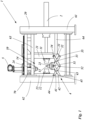
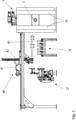
- figure 1 shows a device 1 for die-casting ceramic hollow bodies, with a frame 20 and a die-casting mold 10.
- the frame 10 has a right-hand post 61 and a left-hand post 62, with an upper first guide rail 63 and a lower second guide rail 64 being arranged between the two posts are.
- the guide rails 63 and 64 are each formed by two guide axes.
- the die 10 is arranged on the guide rails 63 and 64 .
- the die 10 consists of a right side mold part 11, a left side mold part 12, a base mold part 13 and a head mold part 14.
- the right side mold part 11 is arranged on a right side carriage 21.
- the left side molding 12 is arranged on a left side carriage 22 .
- the bottom mold part 13 is arranged on a lower mold carriage 23 .
- the head mold part 14 is arranged on a head carriage 24 .
- figure 1 an open die casting mold 10 is shown. In the closed state, the right side mold part 11, the left side mold part 12, the base mold part 13 and the top mold part 14 form a cavity 3 (not shown in FIG figure 1 ).
- the left side carriage 22 is fixedly arranged on the left post 62 and is held supported on the first and second guide rails 63, 64 at the same time.
- the right-hand side carriage 21 is movably mounted between the two guide rails 63 and 64 and can be moved horizontally along the guide rails via a drive 2 .
- the lower mold carriage 23 is mounted on the lower guide rail 64 so that it can move in the horizontal direction.
- the head carriage 24 is in the embodiment figure 1 fixedly arranged on the left side carriage 22.
- the guide ensures a precise opening and closing of the mold parts of the die casting molds. Because the mold parts are movably mounted on the guide, the mold parts are opened essentially in a straight line.
- the mold parts are preferably opened without play in a direction perpendicular to the opening or closing direction. This will It is avoided that transverse forces act on the shards, which are caused by a movement of the molded parts perpendicular to the opening or closing direction.
- the drive 2 includes a hydraulic cylinder and a plunger, which is connected to the right-hand side carriage 21 and acts on it in the opening or closing direction. It is also possible for the drive 2 to be in the form of a linear drive, in particular a linear drive with a hydraulic cylinder, or as a linear drive with a compressed air cylinder or as a linear drive with an electric spindle drive.
- the right lateral carriage 21, the left lateral carriage 22 and the lower mold carriage 23 are movably connected to one another via a linkage 4.
- the linkage 4 between the right side travel carriage 21 and the lower mold carriage 23 has two arms, a first right arm 31 and a second right arm 32 which are connected to one another by a right arm swivel joint 33 .
- the first right arm 31 is rotatably supported by a right side travel carriage pivot 34 on the right side travel carriage 21 and the second right arm 32 is rotatably supported by a lower mold carriage pivot 51 on the lower mold carriage 23 .
- the linkage 4 has two arms between the left lateral travel carriage 22 and the lower mold carriage 23 , a first left arm 41 and a second left arm 42 which are connected to one another by a left arm swivel joint 43 .
- the first left arm 41 is rotatably supported by a left side travel carriage pivot 44 on the left side travel carriage 22 and the second left arm 42 is rotatably supported by a lower mold carriage pivot 51 on the lower mold carriage 23 .
- first right arm 31 and the first left arm 41 of the linkage 4 are pivotally connected to each other via a central frame pivot 52 .
- the second right and left arms 32 and 42 are rotatably connected to each other via the lower mold carriage pivot joint 51 but thereby obtain a rotatable fixed point on the lower mold carriage 23.
- the first and second right and left arms form a scissor linkage.
- the device in figure 1 shifted by the drive 2 of the right lateral carriage 21 to the left in the direction of the left lateral carriage 22 and thereby also the lower mold carriage 23 shifted to the left in the direction of the left lateral carriage 22 by the linkage 4. Due to the connection via the linkage and the resulting synchronous movement of the lateral carriages 21 and 22 and the lower mold carriage 23 when the die-casting mold 10 is closed, the distance between the right lateral carriage 21 and the lower mold carriage 23 remains exactly the same as the distance between the left lateral carriage 22 and the lower mold carriage 23.
- the right side carriage swivel joint 34, the left side carriage swivel joint 44 and the lower mold carriage swivel joint 51 are designed as rotatable fixed points of the linkage 4, which move relative to one another when one of the carriages is moved.
- the linkage By designing the linkage as a double scissor linkage, the synchronous movement of the carriages can be achieved.
- the closing movement the right and left side carriages 21 and 22 and the lower mold carriage 23 are pushed together, in particular in a straight line, and pulled apart in a later opening movement in an opposite opening direction, in particular in a straight line.
- the right side mold part 11, the left side mold part 12 and the bottom mold part 13 are first transferred to the closed, ie pushed together state. Then the head mold part 14 is lowered from above by the head drive 5 onto the already closed mold parts 11, 12 and 13 and thus closes the die casting mold 10.
- the die casting mold 10 in figure 1 has a slip conveying device 70, whereby the slip is pumped into the cavity 3 (not shown in FIG figure 1 ) of the die 10 is injected or flows into the cavity 3.
- the slip conveying device 70 fills the die casting mold 10 from above. This has the advantage that the injection of the liquid slip is assisted by gravity and the injection time is therefore reduced.
- the liquid slip under pressure which is preferably generated by a pump, into the die casting mold 10 is injected.
- slip and/or compressed air can be introduced into a cavity 3 of the die casting mold 10 through the bottom mold part 13 or through the top mold part 14 .
- the shard can be removed after opening the die-casting mold 10.
- the head molding 14 is moved upwards away from the sherd by the head drive 5.
- the die casting mold 10 is then opened completely by the drive 2 moving the right side carriage 21 to the right, ie moving it away from the left side carriage 22 .
- the lower mold carriage 23 is also moved to the right by the linkage 4 , ie it is moved away from the left side carriage 22 .
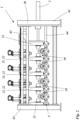
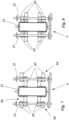
- figure 2 1 shows a second exemplary embodiment of the device 1 according to the invention for die-casting ceramic hollow bodies with open die-casting molds 10.
- This exemplary embodiment differs from the exemplary embodiment in FIG figure 1 only in that several die casting molds 10 are arranged one behind the other, ie in the opening or closing direction.
- the first right side traveling carriage 21 is driven by the drive 2 in the opening or closing direction.
- the linkage 4 preferably through the scissors arrangement of the arms in the linkage 4, all dies 10 are opened or closed simultaneously, synchronously. Due to the connection via the linkage and the resulting synchronous movement of the side carriages 21 and 22 and the lower mold carriage 23 when all die casting molds 10 are closed, the distance between all right side carriages 21 and all lower mold carriages 23 remains just as large as the distance between all left side carriages 22 and all lower mold slides 23 of the respective die 10. This also applies to the opening movement of the device 1.
- all dies 10 have a right side mold part 11, a left side mold part 12, a bottom mold part 13 and a head mold part 14.
- the arrangement of the molded parts differs in figure 2 but from the embodiment of figure 1 .
- Each die 10 has its own lower mold carriage 23 .
- the individual die casting molds 10 share some of the carriages.
- the left side carriage 22 of the far right die-casting mold 10 is at the same time the right side carriage 21 of the second die-casting mold 10 from the right. Only on the two side carriages at the edge, ie the far right side carriage 21 which is connected to the drive 4 and the far left side carriage 22 which is connected to the frame 20, only one molded part is arranged.
- part of the right side carriage 21 of the first die casting mold 10 forms the left side carriage 22 of a second die casting mold.
- the right side carriage pivot 34 of the first die 10 forms the left side carriage pivot 44 of a second die.
- left side carriage 22 in the figure 2 in which case the left side carriage 22 of the first die 10 forms the right side carriage 21 of a second die 10 for a portion of the plurality of dies 10, and that the left side carriage pivot joint 44 of the first die 10 forms the right side carriage for a portion of the plurality of dies 10 -Swivel joint 34 forms a second die, as in figure 2 is shown.
- figure 2 10 further shows that the linkage 4 corresponding to the multiple dies 10 is designed in such a way that in some of the multiple dies 10 the first right arm 31 of a first die 10 is connected to the first left arm 41 of a second die 10 via a right frame pivot joint 35 is rotatably connected, and in a part of the plurality of dies 10, the first left arm 31 of the first die 10 is rotatably connected to the left first arm 41 of the second die 10 via a right frame pivot 35.
- a synchronous movement of all the die casting molds 10 and the respective mold parts relative to one another is thus obtained.
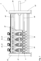
- figure 3 shows the device for die casting of ceramic hollow bodies from figure 2 with closed die casting molds 10.
- the drive 2 and the linkage 4 pushed all the die casting molds 10 and thus all the side mold parts to the bottom mold parts together synchronously, and in a final step the respective head carriage 24 with the head mold parts 14 was then pushed onto the top drive 5 by the respective top drive 5 Side mold parts down and the die-casting molds 10 have been closed with it.
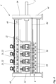
- figure 4 shows the device for die casting of ceramic hollow bodies from figures 2 and 3 with closed dies 10 as in figure 3 as a sectional view in the area of the second guide rail 64.
- the guide rail 64 designed as a guide shaft in this exemplary embodiment, extends through the right-hand lateral carriage 21, the left-hand lateral carriage 22 and the lower mold carriage 23.
- the guide ensures that the mold parts of the die-casting molds are opened and closed with a precise fit. Because the mold parts are movably mounted on the guide, the mold parts are opened essentially in a straight line.
- the mold parts are preferably opened without play in a direction perpendicular to the opening or closing direction. This avoids transverse forces acting on the shards that are caused by a movement of the molded parts perpendicular to the opening or closing direction.
- the first guide rail 63 can be designed as a guide shaft.
- the figures 5 and 6 show a side view and a top view of a device 1 according to the invention for die-casting ceramic hollow bodies with a gripping device 80, a drying station 71, a gripping robot 84 and a conveyor belt 85. These are arranged in the immediate vicinity of the die-casting device 1. Due to this compact design, due to the short Traverse paths of the gripping device 3, the cycle times are reduced, which in turn results in a higher number of items.
- the gripping device 80 includes a trolley 81 which is movably mounted along guides, so that the trolley 81 can be moved in a translatory manner perpendicular to the opening and closing direction of the die casting molds 10 .
- the trolley 81 is powered by a linear motor or servo motor, or pneumatically or hydraulically.
- a gripping column 82 is preferably mounted on the trolley, which in turn has one or more of the gripping arms 83 .
- the gripping device 80 has a plurality of parallel gripping arms 83 (see figure 6 ), each gripping arm 83 being associated with a die 10 .
- a plurality of gripping tools corresponding to the number of cavities 3 per die 10 are arranged on each gripping arm 83 .
- the die casting molds 10 can have a plurality of cavities 3 which are arranged one behind the other in a straight line.
- the gripping arms 83 extend essentially perpendicularly to the opening direction or closing direction of the die casting molds 10.
- the gripper arms 83 are driven to move perpendicularly to the opening direction or closing direction in order to transport away the shards removed from the die casting molds 10 .
- the gripping device 80 grips or fixes all fragments in the die casting molds 10 synchronously, with the discs being arranged on the base mold part 13 after the die casting molds 10 have been opened. After the shards have been gripped by the gripping device 80, it is provided that the shards are fed to a drying station 71 in order to completely and/or partially dry or harden them there for further processing and/or further transport. It is also possible for the drying and/or curing step to be omitted or carried out at a later point in time.
- the letters are transferred to a spindle belt 72 or a conveyor belt 11 by the gripping device 80 .
- the shards arranged one behind the other in a row on the drying station 71 are transferred piece by piece to the spindle belt 72 one after the other.
- the spindle belt 72 can serve as a means of transport or for positioning the shards when they are in the working area of the cleaning stations.
- the spindle belt 72 or the conveyor belt 85 which can also be loaded by a gripping robot 84, feeds the shards to other systems, where post-treatment of the shards is carried out.
- the shards can be glazed and/or printed, in particular with a protective layer, preferably a transparent protective layer, being applied, which protects the shards from mechanical and/or physical and/or chemical environmental influences.
- the shard can be colored so that individual ceramic products can be produced that create a particularly high-quality visual impression.
- the shard is post-processed by means of mechanical forming methods, such as milling and/or drilling.
- the Figures 7 and 8 show an exemplary embodiment of the guide rail 64 in a schematic sectional representation of the device for die casting 1 in the closed and open state of the die casting molds 10.
- the section of the representations runs in the horizontal direction at the level of the lower mold carriage 23 as an example through one of the devices 1 for die casting of the preceding exemplary embodiments with several Die casting molds 10, wherein in the embodiment of Figures 7 and 8 separate second guide rails 64 are formed for each die 10 .
- a lower guide rail 64 is designed as a double, or double, guide shaft 65 for each individual die casting mold 10, which guides the right lateral carriage 21, the left lateral carriage 22 and the lower mold carriage 24 of a die casting mold 10 in plain bearings.
- the two lower guide shafts 65 of each separate guide rail 64 are arranged horizontally one behind the other.
- the lower guide rails 64 on the left or right of adjacent dies 10 are each designed as further separate lower guide rails 64 each with two (double) guide shafts 65 .
- the figure 7 shows on the left side of the left side carriage 22 and the right side of the right side carriage 21 two further guide shafts 65 of the separate guide rails 64 of the adjacent die-casting molds 10.
- the guide shafts 65 of different die-casting molds 10, as in Figures 7 and 8 shown offset from each other in the horizontal plane.
Landscapes
- Engineering & Computer Science (AREA)
- Ceramic Engineering (AREA)
- Chemical & Material Sciences (AREA)
- Manufacturing & Machinery (AREA)
- Mechanical Engineering (AREA)
- Dispersion Chemistry (AREA)
- Moulds, Cores, Or Mandrels (AREA)
- Battery Electrode And Active Subsutance (AREA)
Claims (13)
- Dispositif (1) pour le moulage sous pression d'un corps creux en céramique, comprenant un cadre (20) etdeux moules de moulage sous pression (10) ou plus, disposés sur le cadre (20), dans lequel les deux moules de moulage sous pression (10) ou plus comprennent chacun au moins trois parties de moule, une partie de moule latérale droite (11), une partie de moule latérale gauche (12) et une partie de moule de fond (13) etdans lequel la partie de moule latérale droite (11) est disposée sur un chariot de déplacement latéral droit (21) et dans lequel la partie de moule latérale gauche (12) est disposée sur un chariot de déplacement latéral gauche (22) et dans lequel la partie de moule de fond (13) est disposée sur un chariot de moule inférieur (23),dans lequel le chariot de déplacement latéral droit (21), le chariot de déplacement latéral gauche (22) et le chariot de moule inférieur (23) sont logés de manière mobile les uns par rapport aux autres etdans lequel le dispositif (1) comprend en outre un dispositif d'entraînement (2) afin de déplacer le chariot de déplacement latéral droit (21), le chariot de déplacement latéral gauche (22) et le chariot de moule inférieur (23) les uns par rapport aux autres de façon à ce que les parties de moule (11, 12, 13) soient ouvertes ou fermées etde façon à ce que les deux moules de moulage sous pression (10) ou plus forment chacun, dans l'état fermé, au moins une cavité (3), etle chariot de déplacement latéral droit (21) et le chariot de déplacement latéral gauche (22) et le chariot de moule inférieur (23) sont reliés entre eux par l'intermédiaire d'une tringlerie (4) etla tringlerie (4) est conçue de façon à ce que, lors de l'ouverture et/ou lors de la fermeture, le chariot de déplacement latéral droit (21) et/ou le chariot de déplacement latéral gauche (22) et/ou le chariot de moule inférieur (23) soi(en)t déplacés etla tringlerie (4) est conçue de façon à ce que, lors de l'ouverture et lors de la fermeture, la partie de moule latérale droite (11) et la partie de moule latérale gauche (12) se rapprochent ou s'éloignent de manière synchrone de la partie de moule de fond (13),caractérisé en ce quepour le démoulage des fragments formés dans les deux moules de moulage sous pression (10) ou plus, un dispositif de préhension (80) est disposé sur le cadre (20), qui est conçu pour la fixation ou la préhension synchrone ou simultanée des fragments.
- Dispositif (1) pour le moulage sous pression selon la revendication 1,
caractérisé en ce que
la tringlerie (4) est conçue comme une tringlerie en ciseaux, de préférence comme une double tringlerie en ciseaux. - Dispositif (1) pour le moulage sous pression selon la revendication 1 ou 2,
caractérisé en ce que
la tringlerie (4) comprend, entre le chariot de déplacement latéral droit (21) et le chariot de moule inférieur (23), deux bras, un premier bras droit (31) et un deuxième bras droit (32), qui sont reliés entre eux à l'aide d'une articulation rotative de bras droit (33) et dans lequel le premier bras droit (31) est logé de manière rotative à l'aide d'une articulation rotative de chariot de déplacement latéral droit (34) au niveau du chariot de déplacement latéral droit (21) et le deuxième bras droit (32) est logé de manière rotative à l'aide d'une articulation rotative de chariot de moule inférieur (51) au niveau du chariot de moule inférieur (23). - Dispositif (1) pour le moulage sous pression selon l'une des revendications 1 à 3,
caractérisé en ce que
la tringlerie (4) comprend, entre le chariot de déplacement latéral gauche (22) et le chariot de moule inférieur (23), deux, bras, un premier bras gauche (41) et un deuxième bras gauche (42), qui sont reliés entre eux à l'aide d'une articulation rotative de bras gauche (43) et dans lequel le premier bras gauche (41) est logé de manière rotative à l'aide d'une articulation rotative de chariot de déplacement latéral gauche (44) au niveau du chariot de déplacement latéral gauche (22) et le deuxième bras gauche (42) est logé de manière rotative à l'aide d'une articulation rotative de chariot de moule inférieur (51) au niveau du chariot de moule inférieur (23). - Dispositif pour le moulage sous pression selon l'une des revendications précédentes,
caractérisé en ce que
les plusieurs moules de moulage sous pression (10) sont disposés les uns à côté des autres sur le même chariot de déplacement latéral (21) et le chariot de déplacement latéral (22) et le chariot de moule inférieur (23). - Dispositif pour le moulage sous pression selon l'une des revendications précédentes,
caractérisé en ce que
les plusieurs moules de moulage sous pression (10) sont disposés les uns derrière les autres, de préférence dans la direction d'ouverture et/ou de fermeture, dans lequel les plusieurs moules de moulage sous pression (10) sont disposés chacun sur son propre chariot de déplacement latéral droit (21) et/ou chariot de déplacement latéral gauche (22) et/ou chariot de moule inférieur (23). - Dispositif pour le moulage sous pression selon l'une des revendications précédentes,
caractérisé en ce que
le moule de moulage sous pression (10) forme, dans l'état fermé, deux cavités (3) ou plus. - Dispositif pour le moulage sous pression selon l'une des revendications précédentes,
caractérisé en ce que
l'articulation rotative de châssis (52) présente un jeu et/ou en ce que l'articulation rotative de châssis droite (35) et/ou l'articulation rotative de châssis gauche (45) présente un jeu. - Dispositif pour le moulage sous pression selon la revendication 8,
caractérisé en ce que
le jeu des articulations se trouve dans un intervalle de 5 à 0,5 mm, de préférence entre 3 et 1 mm, de préférence encore entre 2,5 et 1,5 mm. - Dispositif pour le moulage sous pression selon l'une des revendications précédentes,
caractérisé en ce que
le moule de moulage sous pression (10) comprend une quatrième partie de moule, une partie de moule de tête (14), qui est disposée sur un chariot de tête (24). - Dispositif pour le moulage sous pression selon la revendication 10,
caractérisé en ce que
le chariot de tête (24) est disposé sur le chariot de déplacement latéral droit ou gauche (21, 22) ou sur la tringlerie (4) et il est déplacé, lors du mouvement d'ouverture et de fermeture, conjointement avec le chariot de déplacement latéral droit (21) ou le chariot de déplacement latéral gauche (22) ou seul, à l'aide de la tringlerie (4), et de préférence en ce que le chariot de tête (24) comprend un entraînement de tête (5) qui déplace la partie de moule de tête (14) à partir du haut vers la partie de moule latérale gauche et droite (21, 22), afin de fermer entièrement le moule de moulage sous pression (10). - Procédé de fabrication de corps creux en céramique, plus particulièrement au moyen d'un moulage sous pression de céramique, de préférence avec un dispositif de moulage sous pression de corps creux en céramique selon l'une des revendications 1 à 11, dans lequel le corps creux en céramique est fabriqué avec les étapes suivantes :i) rapprochement synchrone d'une partie de moule latérale droite de la partie de moule de fond et d'une partie de moule latérale gauche de la partie de moule de fond des deux moules de moulage sous pression ou plus à l'aide d'un entraînement et d'une tringlerie,ii) déplacement vers le bas d'une partie de moule de tête à l'aide d'un entraînement de tête vers les parties de moule latérales,iii) introduction de barbotine dans une cavité des deux moules de moulage sous pression ou plus afin de former un fragment,iv) déplacement vers le haut de la partie de moule de tête à l'aide de l'entraînement de tête,v) éloignement synchrone de la partie de moule latérale droite de la partie de moule de fond et de la partie de moule latérale gauche de la partie de moule de fond à l'aide de l'entraînement et de la tringlerie,caractérisé par l'étape suivante :
vi) fixation ou préhension synchrone ou simultanée des fragments pour le démoulage des fragments formés dans les au moins deux moules de moulage sous pression à l'aide d'un dispositif de préhension qui est disposé sur le cadre. - Procédé de moulage sous pression selon la revendication 12,
caractérisé en ce quele procédé est exécuté avec un dispositif qui comprend deux moules de moulage sous pression (10) ou plus, qui comprennent respectivement plusieurs parties de moule mobiles les unes par rapport aux autres, une partie de moule latérale droite, une partie de moule latérale gauche, une partie de moule de fond et une partie de moule de tête etdans lequel les parties de moule forment, dans l'état fermé, au moins une cavité,dans lequel la partie de moule latérale droite (11) est disposée sur un chariot de déplacement latéral droit (21) et dans lequel la partie de moule latérale gauche (12) est disposée sur un chariot de déplacement latéral gauche (22) et dans lequel la partie de moule de fond (13) est disposée sur un chariot de moule inférieur (23) et dans lequel la partie de moule de tête est disposée sur un chariot de tête (24) etdans lequel le chariot de déplacement latéral droit (21), le chariot de déplacement latéral gauche (22) et le chariot de moule inférieur (23) et le chariot de tête (24) sont logés de manière mobile les uns par rapport aux autres etdans lequel, par l'intermédiaire d'un entraînement, le chariot de déplacement latéral droit (21), le chariot de déplacement latéral gauche (22) et le chariot de moule inférieur (23) sont déplaçables les uns par rapport aux autres et dans lequel, par l'intermédiaire d'un entraînement de tête (5), le chariot de moule de tête est déplaçable etdans lequel les deux moules de moulage sous pression ou plus, constitués des parties de moules, sont ouverts et/ou fermés par l'entraînement (2) et l'entraînement de tête (5) et les deux moules de moulage sous pression (10) ou plus forment, dans l'état fermé, au moins une cavité (3) etdans lequel au moins le chariot de moule latéral droit, le chariot de moule latéral gauche et le chariot de moule inférieur sont reliés entre eux par l'intermédiaire d'une tringlerie etdans lequel la tringlerie (4) est conçue de façon à ce que, lors de l'ouverture et lors de la fermeture, la partie de moule latérale droite (11) et la partie de moule latérale gauche (12) se rapprochent ou s'éloignent de manière synchrone de la partie de moule de fond (13).
Priority Applications (1)
| Application Number | Priority Date | Filing Date | Title |
|---|---|---|---|
| EP22211846.5A EP4166295A1 (fr) | 2020-05-28 | 2021-05-27 | Coulée sous pression à batterie du corps creux en céramique |
Applications Claiming Priority (1)
| Application Number | Priority Date | Filing Date | Title |
|---|---|---|---|
| DE102020114348.6A DE102020114348A1 (de) | 2020-05-28 | 2020-05-28 | Batteriedruckguss keramischer Hohlkörper |
Related Child Applications (2)
| Application Number | Title | Priority Date | Filing Date |
|---|---|---|---|
| EP22211846.5A Division EP4166295A1 (fr) | 2020-05-28 | 2021-05-27 | Coulée sous pression à batterie du corps creux en céramique |
| EP22211846.5A Division-Into EP4166295A1 (fr) | 2020-05-28 | 2021-05-27 | Coulée sous pression à batterie du corps creux en céramique |
Publications (4)
| Publication Number | Publication Date |
|---|---|
| EP3915744A2 EP3915744A2 (fr) | 2021-12-01 |
| EP3915744A3 EP3915744A3 (fr) | 2022-01-19 |
| EP3915744C0 EP3915744C0 (fr) | 2023-07-12 |
| EP3915744B1 true EP3915744B1 (fr) | 2023-07-12 |
Family
ID=76159347
Family Applications (2)
| Application Number | Title | Priority Date | Filing Date |
|---|---|---|---|
| EP21176249.7A Active EP3915744B1 (fr) | 2020-05-28 | 2021-05-27 | Coulée sous pression à batterie du corps creux en céramique |
| EP22211846.5A Pending EP4166295A1 (fr) | 2020-05-28 | 2021-05-27 | Coulée sous pression à batterie du corps creux en céramique |
Family Applications After (1)
| Application Number | Title | Priority Date | Filing Date |
|---|---|---|---|
| EP22211846.5A Pending EP4166295A1 (fr) | 2020-05-28 | 2021-05-27 | Coulée sous pression à batterie du corps creux en céramique |
Country Status (2)
| Country | Link |
|---|---|
| EP (2) | EP3915744B1 (fr) |
| DE (1) | DE102020114348A1 (fr) |
Family Cites Families (20)
| Publication number | Priority date | Publication date | Assignee | Title |
|---|---|---|---|---|
| IT1196961B (it) * | 1986-07-11 | 1988-11-25 | Nassetti Ettore Spa | Pressa perfezionata per la produzione di articoli sanitari |
| IT1268829B1 (it) | 1994-06-02 | 1997-03-13 | Ideal Standard | Banco automatico di colatura a pressione |
| DE19520234C1 (de) | 1995-06-01 | 1996-07-18 | Netzsch Erich Holding | Anlage zum Druckgießen keramischer Artikel |
| IT1294441B1 (it) | 1997-06-17 | 1999-03-24 | Sacmi | Impianto per il colaggio in pressione di articoli sanitari |
| IT1304574B1 (it) * | 1998-11-06 | 2001-03-19 | Sacmi | Linea per il colaggio in pressione di articoli sanitari e relativostampo. |
| DE19912116A1 (de) | 1999-03-18 | 2000-09-21 | Kautex Maschinenbau Gmbh | Verfahren und Vorrichtung zum Herstellen von Hohlkörpern aus thermoplastischem Kunststoff |
| DE19935595A1 (de) | 1999-08-02 | 2001-02-08 | Dorst Masch & Anlagen | Mehrachsige Druckgußmaschine mit Schwenkachse |
| DE10307669B3 (de) | 2003-02-21 | 2004-10-14 | Maschinen- Und Stahlbau Julius Lippert Gmbh & Co. Kg | Druckgußmaschine |
| DE102004015462B4 (de) * | 2004-03-26 | 2006-03-16 | Maschinen- Und Stahlbau Julius Lippert Gmbh & Co. Kg | Mehrteilige Gießform für den Druckguss von keramischen Formkörpern, deren Verwendung sowie Verfahren mit einer solchen Gießform |
| DE102005002254B3 (de) | 2005-01-18 | 2006-08-10 | Maschinen- Und Stahlbau Julius Lippert Gmbh & Co. Kg | Vorrichtung zur Herstellung von druckgepressten keramischen Gegenständen |
| DE102006021194A1 (de) * | 2006-05-06 | 2007-11-08 | Dorst Technologies Gmbh & Co. Kg | Druckgussanordnung bzw. Druckgussverfahren |
| ITMO20110319A1 (it) | 2011-12-07 | 2013-06-08 | Sir Soc Italiana Resine Spa | Impianto per il colaggio in pressione di articoli igienico-sanitari |
| DE102012004896A1 (de) * | 2012-03-09 | 2013-09-12 | Dorst Technologies Gmbh & Co. Kg | Schlicker-Druckgießform, Schlicker-Druckgießanlage und Druckgießverfahren |
| ITMO20130147A1 (it) * | 2013-05-27 | 2014-11-28 | Sir Soc Italiana Resine Spa | Telaio di sostegno per stampi |
| CN204221936U (zh) | 2014-11-25 | 2015-03-25 | 唐山森兰瓷科技有限公司 | 坐便器自动注浆机 |
| CN105291256B (zh) | 2015-10-30 | 2017-08-22 | 广东省自动化研究所 | 一种卫浴陶瓷多工位同步对称开合模机构 |
| IT201600095433A1 (it) * | 2016-09-22 | 2018-03-22 | Siti B & T Group Spa | Gruppo di formatura per la produzione di articoli sanitari |
| CN207373422U (zh) | 2017-10-19 | 2018-05-18 | 佛山市鸣门卫浴家居有限公司 | 一种用于马桶高压注浆成型的生产线 |
| DE102020100414A1 (de) * | 2020-01-10 | 2021-07-15 | Lippert Gmbh & Co. Kg | Batteriedruckguss für keramische Hohlkörper |
| CN111452184B (zh) * | 2020-04-29 | 2022-05-10 | 周秀兰 | 一种带有自动取坯机头的机器人及一种坯体注浆机 |
-
2020
- 2020-05-28 DE DE102020114348.6A patent/DE102020114348A1/de active Pending
-
2021
- 2021-05-27 EP EP21176249.7A patent/EP3915744B1/fr active Active
- 2021-05-27 EP EP22211846.5A patent/EP4166295A1/fr active Pending
Also Published As
| Publication number | Publication date |
|---|---|
| EP4166295A1 (fr) | 2023-04-19 |
| EP3915744C0 (fr) | 2023-07-12 |
| EP3915744A3 (fr) | 2022-01-19 |
| EP3915744A2 (fr) | 2021-12-01 |
| DE102020114348A1 (de) | 2021-12-02 |
Similar Documents
| Publication | Publication Date | Title |
|---|---|---|
| EP3851262B1 (fr) | Coulée sous pression de batterie pour corps creux en céramique | |
| DE69217870T2 (de) | Verfahren und Vorrichtung zum Giessen von Kunststoffverbundmaterial | |
| AT409243B (de) | Blasformmaschine | |
| EP2771165B1 (fr) | Procede et dispositif de fabrication de pieces moulees revetues | |
| EP1060063B1 (fr) | Dispositif pour recevoir et transporter des pieces moulees | |
| DE3216332C2 (de) | Vorrichtung zum Herstellen eines dreidimensional geformten Schichtkörpers aus einer kompakten Kunststoffschicht und einer angeschäumten Schaumstoffschicht | |
| EP1044784A1 (fr) | Procédé et dispositif de serrage pour moules de soufflage | |
| EP0074473A1 (fr) | Procédé et dispositif pour la fabrication de pièces de forme ou des objets en matière plastique | |
| EP0810919B1 (fr) | Machine de moulage par injection | |
| EP3915744B1 (fr) | Coulée sous pression à batterie du corps creux en céramique | |
| DE69609225T2 (de) | Verfahren und System zum Verbinden von Formen in kontinuierlich betreibbaren Formungsstrecken, insbesondere für die Herstellung von Konditoreiprodukten | |
| DE1604575A1 (de) | Vorrichtung zum Herstellen von Hohlkoerpern aus thermoplastischem Material im Blasverfahren | |
| EP1053857B1 (fr) | Machine à souffler pour soufflage avec bavures réduites | |
| EP0916472B1 (fr) | Procédé et dispositif pour faire fonctionner une machine de moulage par soufflage à cavités multiples | |
| DE1206571B (de) | Vorrichtung zum Herstellen von Hohlkoerpern aus thermoplastischem Kunststoff | |
| EP1048435A1 (fr) | Procédé et appareil de moulage par injection-soufflage | |
| DE2161247C3 (de) | Vorrichtung zum Herstellen von Hohlkörpern | |
| DE102007041776B4 (de) | Verfahren zum Betrieb einer Blasformvorrichtung mit variabler Schließeneinrichtung | |
| DE102008056670B4 (de) | Verfahren zum Betreiben einer Spritzgießeinrichtung | |
| DE2834976A1 (de) | Verfahren und vorrichtung zur erzeugung von formteilen aus glas, keramik u.dgl. | |
| EP0893230B1 (fr) | Procédé et dispositif pour la fabrication de pièces tridimensionnelles moulées par soufflage réduisant la formation de déchets | |
| EP4344852A1 (fr) | Dispositif de fabrication de corps creux | |
| DE2052460A1 (de) | Verfahren zum kontinuierlichen Aus bilden eines Materialstranges und Vor richtung zum Ausfuhren des Verfahrens | |
| DE3115883A1 (de) | Verfahren zum herstellen von produkten aus thermoplastischem material und vorrichtung zur durchfuehrung des verfahrens | |
| DE2204395B2 (de) | Vorrichtung zum herstellen von hohlkoerpern aus thermoplastischem kunststoff im blasverfahren |
Legal Events
| Date | Code | Title | Description |
|---|---|---|---|
| PUAI | Public reference made under article 153(3) epc to a published international application that has entered the european phase |
Free format text: ORIGINAL CODE: 0009012 |
|
| STAA | Information on the status of an ep patent application or granted ep patent |
Free format text: STATUS: THE APPLICATION HAS BEEN PUBLISHED |
|
| AK | Designated contracting states |
Kind code of ref document: A2 Designated state(s): AL AT BE BG CH CY CZ DE DK EE ES FI FR GB GR HR HU IE IS IT LI LT LU LV MC MK MT NL NO PL PT RO RS SE SI SK SM TR |
|
| PUAL | Search report despatched |
Free format text: ORIGINAL CODE: 0009013 |
|
| AK | Designated contracting states |
Kind code of ref document: A3 Designated state(s): AL AT BE BG CH CY CZ DE DK EE ES FI FR GB GR HR HU IE IS IT LI LT LU LV MC MK MT NL NO PL PT RO RS SE SI SK SM TR |
|
| RIC1 | Information provided on ipc code assigned before grant |
Ipc: B28B 13/06 20060101ALI20211215BHEP Ipc: B28B 13/02 20060101ALI20211215BHEP Ipc: B28B 1/26 20060101AFI20211215BHEP |
|
| STAA | Information on the status of an ep patent application or granted ep patent |
Free format text: STATUS: REQUEST FOR EXAMINATION WAS MADE |
|
| 17P | Request for examination filed |
Effective date: 20220503 |
|
| RBV | Designated contracting states (corrected) |
Designated state(s): AL AT BE BG CH CY CZ DE DK EE ES FI FR GB GR HR HU IE IS IT LI LT LU LV MC MK MT NL NO PL PT RO RS SE SI SK SM TR |
|
| GRAP | Despatch of communication of intention to grant a patent |
Free format text: ORIGINAL CODE: EPIDOSNIGR1 |
|
| STAA | Information on the status of an ep patent application or granted ep patent |
Free format text: STATUS: GRANT OF PATENT IS INTENDED |
|
| INTG | Intention to grant announced |
Effective date: 20220916 |
|
| TPAC | Observations filed by third parties |
Free format text: ORIGINAL CODE: EPIDOSNTIPA |
|
| GRAJ | Information related to disapproval of communication of intention to grant by the applicant or resumption of examination proceedings by the epo deleted |
Free format text: ORIGINAL CODE: EPIDOSDIGR1 |
|
| STAA | Information on the status of an ep patent application or granted ep patent |
Free format text: STATUS: REQUEST FOR EXAMINATION WAS MADE |
|
| INTC | Intention to grant announced (deleted) | ||
| GRAP | Despatch of communication of intention to grant a patent |
Free format text: ORIGINAL CODE: EPIDOSNIGR1 |
|
| STAA | Information on the status of an ep patent application or granted ep patent |
Free format text: STATUS: GRANT OF PATENT IS INTENDED |
|
| INTG | Intention to grant announced |
Effective date: 20230301 |
|
| GRAS | Grant fee paid |
Free format text: ORIGINAL CODE: EPIDOSNIGR3 |
|
| GRAA | (expected) grant |
Free format text: ORIGINAL CODE: 0009210 |
|
| STAA | Information on the status of an ep patent application or granted ep patent |
Free format text: STATUS: THE PATENT HAS BEEN GRANTED |
|
| AK | Designated contracting states |
Kind code of ref document: B1 Designated state(s): AL AT BE BG CH CY CZ DE DK EE ES FI FR GB GR HR HU IE IS IT LI LT LU LV MC MK MT NL NO PL PT RO RS SE SI SK SM TR |
|
| REG | Reference to a national code |
Ref country code: CH Ref legal event code: EP |
|
| REG | Reference to a national code |
Ref country code: IE Ref legal event code: FG4D Free format text: LANGUAGE OF EP DOCUMENT: GERMAN |
|
| REG | Reference to a national code |
Ref country code: DE Ref legal event code: R096 Ref document number: 502021000989 Country of ref document: DE |
|
| U01 | Request for unitary effect filed |
Effective date: 20230802 |
|
| U07 | Unitary effect registered |
Designated state(s): AT BE BG DE DK EE FI FR IT LT LU LV MT NL PT SE SI Effective date: 20230808 |
|
| REG | Reference to a national code |
Ref country code: LT Ref legal event code: MG9D |
|
| PG25 | Lapsed in a contracting state [announced via postgrant information from national office to epo] |
Ref country code: GR Free format text: LAPSE BECAUSE OF FAILURE TO SUBMIT A TRANSLATION OF THE DESCRIPTION OR TO PAY THE FEE WITHIN THE PRESCRIBED TIME-LIMIT Effective date: 20231013 |
|
| PG25 | Lapsed in a contracting state [announced via postgrant information from national office to epo] |
Ref country code: ES Free format text: LAPSE BECAUSE OF FAILURE TO SUBMIT A TRANSLATION OF THE DESCRIPTION OR TO PAY THE FEE WITHIN THE PRESCRIBED TIME-LIMIT Effective date: 20230712 |
|
| PG25 | Lapsed in a contracting state [announced via postgrant information from national office to epo] |
Ref country code: IS Free format text: LAPSE BECAUSE OF FAILURE TO SUBMIT A TRANSLATION OF THE DESCRIPTION OR TO PAY THE FEE WITHIN THE PRESCRIBED TIME-LIMIT Effective date: 20231112 |
|
| PG25 | Lapsed in a contracting state [announced via postgrant information from national office to epo] |
Ref country code: RS Free format text: LAPSE BECAUSE OF FAILURE TO SUBMIT A TRANSLATION OF THE DESCRIPTION OR TO PAY THE FEE WITHIN THE PRESCRIBED TIME-LIMIT Effective date: 20230712 Ref country code: NO Free format text: LAPSE BECAUSE OF FAILURE TO SUBMIT A TRANSLATION OF THE DESCRIPTION OR TO PAY THE FEE WITHIN THE PRESCRIBED TIME-LIMIT Effective date: 20231012 Ref country code: IS Free format text: LAPSE BECAUSE OF FAILURE TO SUBMIT A TRANSLATION OF THE DESCRIPTION OR TO PAY THE FEE WITHIN THE PRESCRIBED TIME-LIMIT Effective date: 20231112 Ref country code: HR Free format text: LAPSE BECAUSE OF FAILURE TO SUBMIT A TRANSLATION OF THE DESCRIPTION OR TO PAY THE FEE WITHIN THE PRESCRIBED TIME-LIMIT Effective date: 20230712 Ref country code: GR Free format text: LAPSE BECAUSE OF FAILURE TO SUBMIT A TRANSLATION OF THE DESCRIPTION OR TO PAY THE FEE WITHIN THE PRESCRIBED TIME-LIMIT Effective date: 20231013 Ref country code: ES Free format text: LAPSE BECAUSE OF FAILURE TO SUBMIT A TRANSLATION OF THE DESCRIPTION OR TO PAY THE FEE WITHIN THE PRESCRIBED TIME-LIMIT Effective date: 20230712 |
|
| PG25 | Lapsed in a contracting state [announced via postgrant information from national office to epo] |
Ref country code: PL Free format text: LAPSE BECAUSE OF FAILURE TO SUBMIT A TRANSLATION OF THE DESCRIPTION OR TO PAY THE FEE WITHIN THE PRESCRIBED TIME-LIMIT Effective date: 20230712 |
|
| REG | Reference to a national code |
Ref country code: DE Ref legal event code: R097 Ref document number: 502021000989 Country of ref document: DE |
|
| PG25 | Lapsed in a contracting state [announced via postgrant information from national office to epo] |
Ref country code: SM Free format text: LAPSE BECAUSE OF FAILURE TO SUBMIT A TRANSLATION OF THE DESCRIPTION OR TO PAY THE FEE WITHIN THE PRESCRIBED TIME-LIMIT Effective date: 20230712 Ref country code: RO Free format text: LAPSE BECAUSE OF FAILURE TO SUBMIT A TRANSLATION OF THE DESCRIPTION OR TO PAY THE FEE WITHIN THE PRESCRIBED TIME-LIMIT Effective date: 20230712 Ref country code: CZ Free format text: LAPSE BECAUSE OF FAILURE TO SUBMIT A TRANSLATION OF THE DESCRIPTION OR TO PAY THE FEE WITHIN THE PRESCRIBED TIME-LIMIT Effective date: 20230712 Ref country code: SK Free format text: LAPSE BECAUSE OF FAILURE TO SUBMIT A TRANSLATION OF THE DESCRIPTION OR TO PAY THE FEE WITHIN THE PRESCRIBED TIME-LIMIT Effective date: 20230712 |
|
| PLBE | No opposition filed within time limit |
Free format text: ORIGINAL CODE: 0009261 |
|
| STAA | Information on the status of an ep patent application or granted ep patent |
Free format text: STATUS: NO OPPOSITION FILED WITHIN TIME LIMIT |
|
| 26N | No opposition filed |
Effective date: 20240415 |
|
| U21 | Renewal fee for the european patent with unitary effect paid with additional fee |
Year of fee payment: 4 Effective date: 20240626 |
|
| U1N | Appointed representative for the unitary patent procedure changed after the registration of the unitary effect |
Representative=s name: SCHNEIDER, ANDREAS; DE |
|
| REG | Reference to a national code |
Ref country code: CH Ref legal event code: PL |
|
| PG25 | Lapsed in a contracting state [announced via postgrant information from national office to epo] |
Ref country code: MC Free format text: LAPSE BECAUSE OF FAILURE TO SUBMIT A TRANSLATION OF THE DESCRIPTION OR TO PAY THE FEE WITHIN THE PRESCRIBED TIME-LIMIT Effective date: 20230712 |
|
| PG25 | Lapsed in a contracting state [announced via postgrant information from national office to epo] |
Ref country code: MC Free format text: LAPSE BECAUSE OF FAILURE TO SUBMIT A TRANSLATION OF THE DESCRIPTION OR TO PAY THE FEE WITHIN THE PRESCRIBED TIME-LIMIT Effective date: 20230712 Ref country code: CH Free format text: LAPSE BECAUSE OF NON-PAYMENT OF DUE FEES Effective date: 20240531 |
|
| PG25 | Lapsed in a contracting state [announced via postgrant information from national office to epo] |
Ref country code: IE Free format text: LAPSE BECAUSE OF NON-PAYMENT OF DUE FEES Effective date: 20240527 |
|
| U1K | Transfer of rights of the unitary patent after the registration of the unitary effect |
Owner name: SAMA MASCHINENBAU GMBH; DE |
|
| U20 | Renewal fee for the european patent with unitary effect paid |
Year of fee payment: 5 Effective date: 20250509 |
|
| PGFP | Annual fee paid to national office [announced via postgrant information from national office to epo] |
Ref country code: GB Payment date: 20250519 Year of fee payment: 5 |
|
| PGFP | Annual fee paid to national office [announced via postgrant information from national office to epo] |
Ref country code: TR Payment date: 20250507 Year of fee payment: 5 |
|
| PG25 | Lapsed in a contracting state [announced via postgrant information from national office to epo] |
Ref country code: HU Free format text: LAPSE BECAUSE OF FAILURE TO SUBMIT A TRANSLATION OF THE DESCRIPTION OR TO PAY THE FEE WITHIN THE PRESCRIBED TIME-LIMIT; INVALID AB INITIO Effective date: 20210527 |
|
| PG25 | Lapsed in a contracting state [announced via postgrant information from national office to epo] |
Ref country code: CY Free format text: LAPSE BECAUSE OF FAILURE TO SUBMIT A TRANSLATION OF THE DESCRIPTION OR TO PAY THE FEE WITHIN THE PRESCRIBED TIME-LIMIT; INVALID AB INITIO Effective date: 20210527 |