EP3915744B1 - Battery pressure casting of ceramic hollow bodies - Google Patents
Battery pressure casting of ceramic hollow bodies Download PDFInfo
- Publication number
- EP3915744B1 EP3915744B1 EP21176249.7A EP21176249A EP3915744B1 EP 3915744 B1 EP3915744 B1 EP 3915744B1 EP 21176249 A EP21176249 A EP 21176249A EP 3915744 B1 EP3915744 B1 EP 3915744B1
- Authority
- EP
- European Patent Office
- Prior art keywords
- carriage
- die casting
- mould
- mould part
- die
- Prior art date
- Legal status (The legal status is an assumption and is not a legal conclusion. Google has not performed a legal analysis and makes no representation as to the accuracy of the status listed.)
- Active
Links
Images

Classifications
-
- B—PERFORMING OPERATIONS; TRANSPORTING
- B28—WORKING CEMENT, CLAY, OR STONE
- B28B—SHAPING CLAY OR OTHER CERAMIC COMPOSITIONS; SHAPING SLAG; SHAPING MIXTURES CONTAINING CEMENTITIOUS MATERIAL, e.g. PLASTER
- B28B1/00—Producing shaped prefabricated articles from the material
- B28B1/26—Producing shaped prefabricated articles from the material by slip-casting, i.e. by casting a suspension or dispersion of the material in a liquid-absorbent or porous mould, the liquid being allowed to soak into or pass through the walls of the mould; Moulds therefor ; specially for manufacturing articles starting from a ceramic slip; Moulds therefor
- B28B1/265—Producing shaped prefabricated articles from the material by slip-casting, i.e. by casting a suspension or dispersion of the material in a liquid-absorbent or porous mould, the liquid being allowed to soak into or pass through the walls of the mould; Moulds therefor ; specially for manufacturing articles starting from a ceramic slip; Moulds therefor pressure being applied on the slip in the filled mould or on the moulded article in the mould, e.g. pneumatically, by compressing slip in a closed mould
- B28B1/266—Means for counteracting the pressure being applied on the slip or on the moulded article in the mould, e.g. means for clamping the moulds parts together in a frame-like structure
-
- B—PERFORMING OPERATIONS; TRANSPORTING
- B28—WORKING CEMENT, CLAY, OR STONE
- B28B—SHAPING CLAY OR OTHER CERAMIC COMPOSITIONS; SHAPING SLAG; SHAPING MIXTURES CONTAINING CEMENTITIOUS MATERIAL, e.g. PLASTER
- B28B13/00—Feeding the unshaped material to moulds or apparatus for producing shaped articles; Discharging shaped articles from such moulds or apparatus
- B28B13/02—Feeding the unshaped material to moulds or apparatus for producing shaped articles
- B28B13/0215—Feeding the moulding material in measured quantities from a container or silo
- B28B13/0275—Feeding a slurry or a ceramic slip
-
- B—PERFORMING OPERATIONS; TRANSPORTING
- B28—WORKING CEMENT, CLAY, OR STONE
- B28B—SHAPING CLAY OR OTHER CERAMIC COMPOSITIONS; SHAPING SLAG; SHAPING MIXTURES CONTAINING CEMENTITIOUS MATERIAL, e.g. PLASTER
- B28B13/00—Feeding the unshaped material to moulds or apparatus for producing shaped articles; Discharging shaped articles from such moulds or apparatus
- B28B13/04—Discharging the shaped articles
- B28B13/06—Removing the shaped articles from moulds
Definitions
- the invention relates to a device for die-casting ceramic hollow bodies according to the features of the preamble of claim 1 and a method for producing ceramic hollow bodies by means of ceramic die-casting according to the features of claim 12.
- This known device consists of a multi-part die casting mold which has a lower part, an upper part and side parts which define the mold cavity or cavity.
- the slip gate is flow-mechanically connected to an annular slip distribution chamber, which opens into the mold cavity and presses the slip into it. The pressure is maintained until the ceramic object is completely formed in the mold cavity. The mold is then opened and the ceramic object removed.
- Such a device is only intended for single-item production, which means that large quantities cannot be realized. How the mold parts are opened and closed is not specified in more detail.
- the DE 195 20 234 C1 discloses an apparatus for die-casting hollow ceramic bodies, according to the preamble of claim 1, and a method for producing hollow ceramic bodies, according to the preamble of claim 12.
- the present invention is based on the object of specifying a die-casting device and a method for producing ceramic hollow bodies that meet the increased requirements with regard to high quality of the ceramic hollow bodies.
- the object is achieved according to the invention by a device for die-casting ceramic hollow bodies with the features of claim 1. Furthermore, this object is achieved according to the invention by a method for producing ceramic hollow bodies according to the features of claim 12. According to the invention, a device for die-casting ceramic hollow bodies is proposed, having the features of claim 1.
- the frame can be designed as a supporting frame and have, for example, cross members and longitudinal members connecting them.
- the frame can be designed as a stable support frame for the die casting molds and/or the drive and/or the linkage.
- the object is achieved according to the invention by a method for producing ceramic hollow bodies, wherein the ceramic hollow body is produced with the steps of claim 12.
- the method for the production of ceramic hollow bodies is carried out by means of a device according to the invention for the pressure casting of ceramic hollow bodies.
- the advantage of the device and also the method for the production of ceramic hollow bodies is that the bottom mold part is always arranged centrally between the side mold parts during the opening and/or closing movement, even when using several die casting molds, and during demoulding, i.e. during opening or molding , i.e. when the die-casting mold is closed, the side parts are moved apart or together synchronously. This ensures that the ceramic bodies can also have filigree elements, since such filigree elements, or protruding elements such as a handle of the ceramic body, are retained when demolded and do not tear off.
- a drive with only one drive element for example a stepper motor or a lifting cylinder.
- the drive is in particular designed in such a way that it acts in particular only on the right or in particular only on the left lateral carriage in order to drive the right or the left lateral carriage.
- the drive force and the drive movement are transmitted via the linkage to the remaining carriages of the die-casting mold in order to move them and to close or open the die-casting mold synchronously, in particular at the same time. Provision can be made for the drive to act directly or indirectly on the linkage in order to close or open the die casting mold. Doing this is just a drive for that Form parts necessary, whereby the mold parts can be moved synchronously and different speeds of another drive do not have to be compensated. Furthermore, only one connection to the drive is necessary to open and close all mold parts of the die casting mold.
- the drive is mounted on the frame and drives several of the die-casting molds, preferably all die-casting molds, in order to open them in an opening direction and to close them in the opposite closing direction.
- the linkage is designed as a scissor linkage, preferably as a double scissor linkage.
- a scissors linkage is formed by at least two arms and a swivel joint which pivotally connects the two arms to one another. With a double scissor linkage, four arms are formed. Each pair of arms are connected to one another in the middle via a swivel joint and preferably form an X. The four arms are then connected to one another at one end via two further swivel joints and thus form what is known as a scissor-type lattice.
- the distance between the end and center points of the scissor linkage can be varied.
- the linkage By designing the linkage as a double scissor linkage, the carriages can move synchronously with one another, since the double design can ensure that the distance between the left and right pivot joint to the middle pivot joint remains the same with every movement.
- the linkage between the right-hand lateral carriage and the lower mold carriage has two arms, a first right-hand arm and a second right-hand arm, which are connected to one another by a right-hand arm swivel joint.
- the right arm pivot preferably connecting the two arms together midway.
- the first right arm is pivoted to the right side carriage by a right side carriage pivot and the second right arm is pivoted by a Bottom mold carriage swivel joint mounted rotatably on the bottom mold carriage, and/or that the linkage between the left side carriage and the bottom mold carriage has two arms, a first left arm and a second left arm, which are connected to one another by a left arm swivel joint, the left arm -Swivel joint preferably connects the two arms together in the middle.
- the first left arm is rotatably supported by a left side travel carriage pivot on the left side travel carriage
- the second left arm is rotatably supported by a lower mold carriage pivot on the lower mold carriage.
- the first right arm and the first left arm of the linkage are rotatably connected to one another via a central frame swivel joint.
- the second right arm and the second left arm are rotatably connected to one another via the same lower mold carriage rotary joint.
- the scissor-type lattice is preferably formed in this way.
- Hollow bodies it is provided that two or three or four or five or more die-casting molds, each with at least three mold parts, are arranged in the device, with a right-hand side mold part, a left-hand side mold part and a bottom mold part being formed for each die-cast mold in the device.
- the several die-casting molds are arranged next to one another, wherein preferably in the arrangement next to one another several right-hand side mold parts are arranged on the same right-hand lateral carriage and/or several left-hand side mold parts are arranged on the same left-hand lateral carriage and several bottom mold parts are arranged on the same lower mold carriage.
- cavities can also be formed next to one another in a die-casting mold by one or more mold parts, or several cavities and several die-casting molds can be formed next to one another.
- the several die casting molds are arranged one behind the other, i.e. preferably in the opening and/or closing direction, each with its own right side carriage and/or left side carriage and/or lower mold carriage.
- the several cavities can be formed in each die.
- the multiple die casting molds are arranged next to one another and one behind the other.
- several die-casting molds can be formed one behind the other, i.e. preferably in the opening and/or closing direction, and at the same time several die-casting molds can be formed next to each other for each lateral carriage and/or several cavities per die-casting mold can be formed.
- the right side carriage of the first die casting mold forms the left side carriage of a second die casting mold, and preferably that with several die casting molds the right side carriage rotary joint of the first die-casting mold forms the left-hand lateral travel carriage swivel joint of a second die-casting mold.
- the left-hand side carriage of the first die-casting mold forms the right-hand side carriage of a second die-casting mold
- the left side carriage rotary joint of the first die-casting mold forms the right-hand lateral travel carriage swivel joint of a second die-casting mold
- the left side carriage of the first die forms the right side carriage of a second die, and preferably that in the case of several dies the left side carriage pivot of the first die forms the right side carriage pivot of a second die.
- each die casting mold has at least one side carriage for holding at least one molded part, and with a side carriage arranged between two die casting molds having a molded part on the front side a die-cast mold and on the back a molded part of the other die-cast mold.
- the first right arm of the first die casting mold is rotatably connected to the first left arm of the second die casting mold via a right-hand frame swivel joint, and/or that in the case of several dies the first left arm of the first die is pivotally connected to the left first arm of the second die via a right frame pivot.
- the first right arm of the first die casting mold is rotatably connected to the first left arm of the second die casting mold via a right side carriage rotary joint, and/or that in the case of several Die casting molds the first left arm of the first die is rotatably connected to the left first arm of the second die via a left side carriage pivot.
- a pressure casting mold forms two or preferably more cavities in the closed state. So can three or four or six or eight or ten or even more cavities can be provided on a die casting mold. As a result, the number of ceramic hollow bodies to be produced in one cycle can be correspondingly increased.
- the frame swivel joint has play, in particular a predetermined one, and/or that the right frame swivel joint has play and/or the left frame swivel joint has play, in particular having predetermined play. Dimensional differences in the molded parts and/or the die casting molds can be compensated for by the game.
- the play of the joints is in the range of 5 mm to 0.5 mm, preferably between 3 mm and 1 mm, most preferably between 2.5 mm and 1 .5 mm.
- the die-casting mold has a fourth mold part, a head mold part, which is arranged on a head carriage.
- the head carriage is arranged on the right or on the left side carriage or on the frame and this is moved during the opening and closing movement together with the right side carriage or the left side carriage or solely by the Linkage is moved, and preferably that the head carriage has a head drive, which moves the head mold part from above down onto the left and right side mold parts in order to completely close the die.
- the right-hand side carriage and/or the left-hand side carriage and/or the lower mold carriage is guided over one, or two, or more round shafts, ie guide shafts, with the round shafts preferably being guided are arranged on the frame.
- the guide provides a custom-fit Opening and closing of the mold parts of the die casting molds safely.
- the shape of the cavity always remains the same and there are no unwanted edges that are caused, for example, by improperly closing the molded parts.
- the mold parts are movably mounted on the guide, the mold parts are opened essentially in a straight line.
- the mold parts are preferably opened without play in a direction perpendicular to the opening or closing direction. This avoids transverse forces acting on the shards that are caused by a movement of the molded parts perpendicular to the opening or closing direction.
- the guide it is also possible for the guide to have a straight guide carrier or a straight guide rail or a straight guide rod or a straight guide shaft.
- the several die-casting molds which are preferably arranged one behind the other, the several right-hand side carriages and/or the left-hand side carriages and/or the lower mold carriages are guided one after the other on the one or more round shafts .
- opening the dies in a straight line also ensures that no transverse forces or shearing forces act on the shards, which could possibly deform them unintentionally or even lead to the shard breaking.
- the right and left side mold part always have the same distance to the bottom mold part when closing in step i) and/or when opening in step v).
- step i) takes place by closing the right side carriage and the lower mold carriage are moved, or by closing the left side traveling carriage and the lower mold carriage are moved, or by moving the right side traveling carriage and the left side traveling carriage and the lower mold carriage.
- step v) takes place by moving the right side carriage and the lower mold carriage to the left side carriage when closing, or by moving the left side carriage and the lower mold carriage when closing to the right side carriage, or by moving the right side carriage and the left side carriage and the lower mold carriage.
- compressed air is used to maintain a predetermined air pressure inside the cavities for a specific time in order to solidify the shards located in the cavities.
- a plurality of ceramic hollow bodies can be produced synchronously with the at least two die casting molds and/or the at least two cavities in each case.
- the die casting molds and the cavities are preferably scalable. This means that significantly more than two die casting molds can also be provided.
- An upper limit is defined by the existing installation space in the longitudinal extent of the device, i.e. in the opening and/or closing direction. Practically, die-casting dies in the number of about 4 die-casting dies to 15 die-casting dies can be used. In the case of the cavities, the number of cavities is determined in particular by the installation space available transversely to the longitudinal extension. The use of 4 to 12 cavities per die casting mold has proven to be practical. With appropriate space conditions or with large or small ceramic hollow bodies, more or fewer than this practicable number of cavities or die-casting molds can be used.
- the synchronous filling of the cavities and the synchronous removal of the shards offers the advantage of identical process variables and parameters, which ensures a consistently high quality of the ceramic hollow body and the scrap is reduced. This means that the requirement for large quantities can be met while the quality of the ceramic hollow bodies remains consistently high.
- a cavity is preferably completely filled with liquid slip. Due to dehydration, the liquid slip begins to solidify on the outer contour of the cavity. The dehydration is promoted, for example, by die casting molds made of plaster or porous plastic or other porous materials.
- the solidified part of the slip is also referred to as shards. The longer the shard is in the cavity, the further the water is removed and the thicker the surface layer of the shard is.
- a cavity has an insert or a plurality of inserts or a core part or a plurality of core parts which is/are formed, for example, on a side mold part and/or the base mold part of the die casting mold.
- An insert or core part is, so to speak, a negative of the hollow shape of the ceramic part to be produced.
- no undercut cavities can be formed with an insert.
- an insert is preferably formed through the base molding to form the shape of the ceramic hollow body.
- a ceramic hollow body is to be formed without a core part or insert
- no insert is required to form the shape of the ceramic hollow body.
- undercut cavities for example for bottles, can also be produced.
- the cycle time can be reduced because the liquid slip is blown out by means of compressed air.
- the dwell time of the body in the cavity depends on the shape and the desired edge thickness of the hollow body to be produced. As soon as a predetermined dwell time is reached, the excess liquid slip is then removed from the cavity by means of compressed air blown.
- a gripping device for demolding or removing the shards formed in the at least two or more dies.
- the gripping device can grip and/or remove all fragments formed in a die-casting mold at the same time. Or the gripping device can simultaneously grip and/or remove all fragments formed in the at least two die casting molds, in particular in all die casting molds.
- this enables rapid removal of the shards from the die-casting molds and thus a high number of cycles, and on the other hand, the dwell time of all shards in the die-casting mold or on the gripping device is fixed for the same length.
- a gripping device is arranged on the frame for removing the shards formed in the at least two die casting molds from the mold, which gripping device is designed for synchronous or simultaneous fixing or gripping of the shards.
- the gripping device grips or fixes the shards in the two or more die-casting molds synchronously. It can be provided that a molded part fixing the shards is moved away by the drive when the die-casting molds are opened from the shards fixed in place by the gripping device. It is thus possible, for example, for the shard to be fed to a drying system after it has been removed from the die casting mold, in which the shard dries or hardens partially or completely. The further drying or hardening of the shard ensures that the shard has sufficient strength to be transported further or further processed, for example.
- the die-casting device For further transport, it is preferably possible for the die-casting device to have a conveyor belt, to which the shard is transferred by means of the gripping device.
- the conveyor belt can have holding devices in the form of cups or bowls, which are adapted to the shape of the shard, so that it can be safely transported further.
- the shard is transferred to further systems for post-treatment by means of the gripping device and/or the conveyor belt.
- the sherd can then be mechanically processed, for example by means of milling and/or drilling.
- Printing and/or coating of the shard is preferably also provided.
- the shard can be coated with a protective layer, in particular a transparent protective layer, which protects the ceramic hollow body from mechanical and/or physical and/or chemical environmental influences.
- at least one layer of color can be applied to the shard by means of printing, as a result of which particularly optically high-quality ceramic hollow bodies can be produced. This also applies to multiple fragments from multiple cavities or multiple die casting molds.
- the gripping device has a plurality of parallel gripping arms, each gripping arm being assigned to a die-casting mold and a plurality of gripping tools corresponding to the number of cavities per die-casting mold being arranged on each gripping arm.
- the one or more gripping arms extend essentially perpendicularly to the opening direction or closing direction of the at least two die casting molds.
- gripping arms it is also possible for the gripping arms to be driven so as to be movable perpendicular to the opening direction or closing direction in order to transport away the shards removed from the die casting molds.
- the at least two dies are arranged in a straight line one behind the other in the opening direction or closing direction along the guide.
- the guide it is possible for the guide to be arranged above and/or below the at least two die casting molds.
- the one or more lateral carriages and/or the one or more lower mold carriages are mounted on the guide.
- all side travel carriages and/or lower mold carriages can be movably mounted on the guide in the opening direction and closing direction, in particular displaceably.
- the guide preferably extends over the entire range of movement that the side carriages and/or lower mold carriages cover during a movement.
- the guide can extend in the opening direction or closing direction along the entire frame.
- one embodiment can provide that one of the side carriages is fixed in place on the guide and/or the frame, and that the other side carriages and lower mold carriages, in particular all other side carriages, are movably mounted on the guide.
- the fact that the guide guides the side carriages during an opening movement and/or closing movement ensures that the individual mold parts close with a precise fit and thus always form the same cavity.
- the guide can be designed as a single guide, preferably as an upper guide or as a lower guide.
- the guide can also be made for the guide to have a plurality of guides, for example an upper first guide and a lower second guide, with both guides being a straight guide carrier or a straight Guide rail or a straight guide rod or a straight guide shaft are formed.
- the one or more left and/or right side carriages and/or head carriages of the one or more die casting molds are preferably mounted on the upper first guide.
- the one or more left and/or right side travel carriages and the one or more lower mold carriages are preferably mounted on the lower second guide.
- the lower second guide is designed in several parts.
- the guide can be designed as a separate second lower guide for each die-casting mold, with a left and a right side carriage and a lower mold carriage of a die-casting mold is mounted on the separate second lower guide.
- the side carriages can have one or more slide bearings for the second lower guide.
- the separate lower guides can be offset from one another in each die-casting mold.
- the cavities of a die casting mold preferably the cavities of each of the die casting molds, are preferably arranged next to one another in a direction transverse to the opening direction or closing direction.
- the die-casting molds can be locked against one another via a locking device in order to prevent unintentional opening when pressure is applied to the die-casting molds.
- a locking device in order to prevent unintentional opening when pressure is applied to the die-casting molds.
- the drive locks the die casting molds in the closed position, so that no additional locking device is required.
- the drive it is preferably possible for the drive to synchronously open and/or synchronously close the at least two die casting molds, in particular all die casting molds, preferably by the drive pulling the at least two die casting molds apart in the opening direction, in particular in a straight line, and in an opposite closing direction, in particular in a straight line, moved towards each other.
- the fact that all die casting molds are opened and closed via the same drive via the gear and the die casting molds are mechanically coupled via the gear means that the die casting molds are always opened and closed at the same time. This eliminates the need for a complex controller, since only the drive needs to be controlled to open and close the die casting molds. Furthermore, this ensures that all shards are removed at the same time and that they have the same dwell time in the cavity, which means that differences in quality among the shards are almost impossible.
- opening the dies in a straight line also ensures that no transverse forces or shearing forces act on the shards, which could possibly deform them unintentionally or even lead to the shard breaking.
- the drive is preferably designed as a linear drive, in particular a linear drive with a hydraulic cylinder, or as a linear drive with a compressed air cylinder, or as a linear drive with an electric spindle drive.
- Slip and/or compressed air can preferably be introduced into a cavity of the die casting mold through the base mold part and/or through the top mold part.
- the injection of the slip is assisted by the force of gravity, as a result of which the injection time can be further shortened.
- demoulding all fragments are released synchronously from their die-cast mold by means of an ejection of compressed air.
- the molded parts of all die casting molds holding the shards are moved away synchronously from the shards at the same time as the compressed air blast or after the compressed air blast.
- the shards can initially remain in the bottom mold part of the die casting molds for a predetermined period of time during demoulding.
- the base molding can have a peg in order to shape a cavity of the hollow body to be manufactured.
- the shard can remain on the base molding and/or on the spigot and can continue to dry there and be solidified as a result.
- the shards can be fixed or gripped by the gripping device or transported away from the base molding.
- the die-casting device according to the invention is particularly suitable for the production of ceramic hollow bodies, such as drinking bottles, cups or other drinking vessels.
- Such a die-casting device according to the invention, or a method according to the invention for the production of ceramic hollow bodies offers considerable economic advantages, which accumulate in the production of an increased number of pieces per unit of time and in a reduction in production costs. Due to the constant process parameters and process variables, a consistently high quality of the ceramic hollow body is achieved.
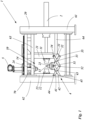
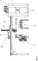
- figure 1 shows a device 1 for die-casting ceramic hollow bodies, with a frame 20 and a die-casting mold 10.
- the frame 10 has a right-hand post 61 and a left-hand post 62, with an upper first guide rail 63 and a lower second guide rail 64 being arranged between the two posts are.
- the guide rails 63 and 64 are each formed by two guide axes.
- the die 10 is arranged on the guide rails 63 and 64 .
- the die 10 consists of a right side mold part 11, a left side mold part 12, a base mold part 13 and a head mold part 14.
- the right side mold part 11 is arranged on a right side carriage 21.
- the left side molding 12 is arranged on a left side carriage 22 .
- the bottom mold part 13 is arranged on a lower mold carriage 23 .
- the head mold part 14 is arranged on a head carriage 24 .
- figure 1 an open die casting mold 10 is shown. In the closed state, the right side mold part 11, the left side mold part 12, the base mold part 13 and the top mold part 14 form a cavity 3 (not shown in FIG figure 1 ).
- the left side carriage 22 is fixedly arranged on the left post 62 and is held supported on the first and second guide rails 63, 64 at the same time.
- the right-hand side carriage 21 is movably mounted between the two guide rails 63 and 64 and can be moved horizontally along the guide rails via a drive 2 .
- the lower mold carriage 23 is mounted on the lower guide rail 64 so that it can move in the horizontal direction.
- the head carriage 24 is in the embodiment figure 1 fixedly arranged on the left side carriage 22.
- the guide ensures a precise opening and closing of the mold parts of the die casting molds. Because the mold parts are movably mounted on the guide, the mold parts are opened essentially in a straight line.
- the mold parts are preferably opened without play in a direction perpendicular to the opening or closing direction. This will It is avoided that transverse forces act on the shards, which are caused by a movement of the molded parts perpendicular to the opening or closing direction.
- the drive 2 includes a hydraulic cylinder and a plunger, which is connected to the right-hand side carriage 21 and acts on it in the opening or closing direction. It is also possible for the drive 2 to be in the form of a linear drive, in particular a linear drive with a hydraulic cylinder, or as a linear drive with a compressed air cylinder or as a linear drive with an electric spindle drive.
- the right lateral carriage 21, the left lateral carriage 22 and the lower mold carriage 23 are movably connected to one another via a linkage 4.
- the linkage 4 between the right side travel carriage 21 and the lower mold carriage 23 has two arms, a first right arm 31 and a second right arm 32 which are connected to one another by a right arm swivel joint 33 .
- the first right arm 31 is rotatably supported by a right side travel carriage pivot 34 on the right side travel carriage 21 and the second right arm 32 is rotatably supported by a lower mold carriage pivot 51 on the lower mold carriage 23 .
- the linkage 4 has two arms between the left lateral travel carriage 22 and the lower mold carriage 23 , a first left arm 41 and a second left arm 42 which are connected to one another by a left arm swivel joint 43 .
- the first left arm 41 is rotatably supported by a left side travel carriage pivot 44 on the left side travel carriage 22 and the second left arm 42 is rotatably supported by a lower mold carriage pivot 51 on the lower mold carriage 23 .
- first right arm 31 and the first left arm 41 of the linkage 4 are pivotally connected to each other via a central frame pivot 52 .
- the second right and left arms 32 and 42 are rotatably connected to each other via the lower mold carriage pivot joint 51 but thereby obtain a rotatable fixed point on the lower mold carriage 23.
- the first and second right and left arms form a scissor linkage.
- the device in figure 1 shifted by the drive 2 of the right lateral carriage 21 to the left in the direction of the left lateral carriage 22 and thereby also the lower mold carriage 23 shifted to the left in the direction of the left lateral carriage 22 by the linkage 4. Due to the connection via the linkage and the resulting synchronous movement of the lateral carriages 21 and 22 and the lower mold carriage 23 when the die-casting mold 10 is closed, the distance between the right lateral carriage 21 and the lower mold carriage 23 remains exactly the same as the distance between the left lateral carriage 22 and the lower mold carriage 23.
- the right side carriage swivel joint 34, the left side carriage swivel joint 44 and the lower mold carriage swivel joint 51 are designed as rotatable fixed points of the linkage 4, which move relative to one another when one of the carriages is moved.
- the linkage By designing the linkage as a double scissor linkage, the synchronous movement of the carriages can be achieved.
- the closing movement the right and left side carriages 21 and 22 and the lower mold carriage 23 are pushed together, in particular in a straight line, and pulled apart in a later opening movement in an opposite opening direction, in particular in a straight line.
- the right side mold part 11, the left side mold part 12 and the bottom mold part 13 are first transferred to the closed, ie pushed together state. Then the head mold part 14 is lowered from above by the head drive 5 onto the already closed mold parts 11, 12 and 13 and thus closes the die casting mold 10.
- the die casting mold 10 in figure 1 has a slip conveying device 70, whereby the slip is pumped into the cavity 3 (not shown in FIG figure 1 ) of the die 10 is injected or flows into the cavity 3.
- the slip conveying device 70 fills the die casting mold 10 from above. This has the advantage that the injection of the liquid slip is assisted by gravity and the injection time is therefore reduced.
- the liquid slip under pressure which is preferably generated by a pump, into the die casting mold 10 is injected.
- slip and/or compressed air can be introduced into a cavity 3 of the die casting mold 10 through the bottom mold part 13 or through the top mold part 14 .
- the shard can be removed after opening the die-casting mold 10.
- the head molding 14 is moved upwards away from the sherd by the head drive 5.
- the die casting mold 10 is then opened completely by the drive 2 moving the right side carriage 21 to the right, ie moving it away from the left side carriage 22 .
- the lower mold carriage 23 is also moved to the right by the linkage 4 , ie it is moved away from the left side carriage 22 .
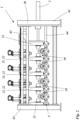
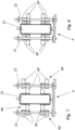
- figure 2 1 shows a second exemplary embodiment of the device 1 according to the invention for die-casting ceramic hollow bodies with open die-casting molds 10.
- This exemplary embodiment differs from the exemplary embodiment in FIG figure 1 only in that several die casting molds 10 are arranged one behind the other, ie in the opening or closing direction.
- the first right side traveling carriage 21 is driven by the drive 2 in the opening or closing direction.
- the linkage 4 preferably through the scissors arrangement of the arms in the linkage 4, all dies 10 are opened or closed simultaneously, synchronously. Due to the connection via the linkage and the resulting synchronous movement of the side carriages 21 and 22 and the lower mold carriage 23 when all die casting molds 10 are closed, the distance between all right side carriages 21 and all lower mold carriages 23 remains just as large as the distance between all left side carriages 22 and all lower mold slides 23 of the respective die 10. This also applies to the opening movement of the device 1.
- all dies 10 have a right side mold part 11, a left side mold part 12, a bottom mold part 13 and a head mold part 14.
- the arrangement of the molded parts differs in figure 2 but from the embodiment of figure 1 .
- Each die 10 has its own lower mold carriage 23 .
- the individual die casting molds 10 share some of the carriages.
- the left side carriage 22 of the far right die-casting mold 10 is at the same time the right side carriage 21 of the second die-casting mold 10 from the right. Only on the two side carriages at the edge, ie the far right side carriage 21 which is connected to the drive 4 and the far left side carriage 22 which is connected to the frame 20, only one molded part is arranged.
- part of the right side carriage 21 of the first die casting mold 10 forms the left side carriage 22 of a second die casting mold.
- the right side carriage pivot 34 of the first die 10 forms the left side carriage pivot 44 of a second die.
- left side carriage 22 in the figure 2 in which case the left side carriage 22 of the first die 10 forms the right side carriage 21 of a second die 10 for a portion of the plurality of dies 10, and that the left side carriage pivot joint 44 of the first die 10 forms the right side carriage for a portion of the plurality of dies 10 -Swivel joint 34 forms a second die, as in figure 2 is shown.
- figure 2 10 further shows that the linkage 4 corresponding to the multiple dies 10 is designed in such a way that in some of the multiple dies 10 the first right arm 31 of a first die 10 is connected to the first left arm 41 of a second die 10 via a right frame pivot joint 35 is rotatably connected, and in a part of the plurality of dies 10, the first left arm 31 of the first die 10 is rotatably connected to the left first arm 41 of the second die 10 via a right frame pivot 35.
- a synchronous movement of all the die casting molds 10 and the respective mold parts relative to one another is thus obtained.
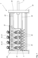
- figure 3 shows the device for die casting of ceramic hollow bodies from figure 2 with closed die casting molds 10.
- the drive 2 and the linkage 4 pushed all the die casting molds 10 and thus all the side mold parts to the bottom mold parts together synchronously, and in a final step the respective head carriage 24 with the head mold parts 14 was then pushed onto the top drive 5 by the respective top drive 5 Side mold parts down and the die-casting molds 10 have been closed with it.
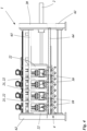
- figure 4 shows the device for die casting of ceramic hollow bodies from figures 2 and 3 with closed dies 10 as in figure 3 as a sectional view in the area of the second guide rail 64.
- the guide rail 64 designed as a guide shaft in this exemplary embodiment, extends through the right-hand lateral carriage 21, the left-hand lateral carriage 22 and the lower mold carriage 23.
- the guide ensures that the mold parts of the die-casting molds are opened and closed with a precise fit. Because the mold parts are movably mounted on the guide, the mold parts are opened essentially in a straight line.
- the mold parts are preferably opened without play in a direction perpendicular to the opening or closing direction. This avoids transverse forces acting on the shards that are caused by a movement of the molded parts perpendicular to the opening or closing direction.
- the first guide rail 63 can be designed as a guide shaft.
- the figures 5 and 6 show a side view and a top view of a device 1 according to the invention for die-casting ceramic hollow bodies with a gripping device 80, a drying station 71, a gripping robot 84 and a conveyor belt 85. These are arranged in the immediate vicinity of the die-casting device 1. Due to this compact design, due to the short Traverse paths of the gripping device 3, the cycle times are reduced, which in turn results in a higher number of items.
- the gripping device 80 includes a trolley 81 which is movably mounted along guides, so that the trolley 81 can be moved in a translatory manner perpendicular to the opening and closing direction of the die casting molds 10 .
- the trolley 81 is powered by a linear motor or servo motor, or pneumatically or hydraulically.
- a gripping column 82 is preferably mounted on the trolley, which in turn has one or more of the gripping arms 83 .
- the gripping device 80 has a plurality of parallel gripping arms 83 (see figure 6 ), each gripping arm 83 being associated with a die 10 .
- a plurality of gripping tools corresponding to the number of cavities 3 per die 10 are arranged on each gripping arm 83 .
- the die casting molds 10 can have a plurality of cavities 3 which are arranged one behind the other in a straight line.
- the gripping arms 83 extend essentially perpendicularly to the opening direction or closing direction of the die casting molds 10.
- the gripper arms 83 are driven to move perpendicularly to the opening direction or closing direction in order to transport away the shards removed from the die casting molds 10 .
- the gripping device 80 grips or fixes all fragments in the die casting molds 10 synchronously, with the discs being arranged on the base mold part 13 after the die casting molds 10 have been opened. After the shards have been gripped by the gripping device 80, it is provided that the shards are fed to a drying station 71 in order to completely and/or partially dry or harden them there for further processing and/or further transport. It is also possible for the drying and/or curing step to be omitted or carried out at a later point in time.
- the letters are transferred to a spindle belt 72 or a conveyor belt 11 by the gripping device 80 .
- the shards arranged one behind the other in a row on the drying station 71 are transferred piece by piece to the spindle belt 72 one after the other.
- the spindle belt 72 can serve as a means of transport or for positioning the shards when they are in the working area of the cleaning stations.
- the spindle belt 72 or the conveyor belt 85 which can also be loaded by a gripping robot 84, feeds the shards to other systems, where post-treatment of the shards is carried out.
- the shards can be glazed and/or printed, in particular with a protective layer, preferably a transparent protective layer, being applied, which protects the shards from mechanical and/or physical and/or chemical environmental influences.
- the shard can be colored so that individual ceramic products can be produced that create a particularly high-quality visual impression.
- the shard is post-processed by means of mechanical forming methods, such as milling and/or drilling.
- the Figures 7 and 8 show an exemplary embodiment of the guide rail 64 in a schematic sectional representation of the device for die casting 1 in the closed and open state of the die casting molds 10.
- the section of the representations runs in the horizontal direction at the level of the lower mold carriage 23 as an example through one of the devices 1 for die casting of the preceding exemplary embodiments with several Die casting molds 10, wherein in the embodiment of Figures 7 and 8 separate second guide rails 64 are formed for each die 10 .
- a lower guide rail 64 is designed as a double, or double, guide shaft 65 for each individual die casting mold 10, which guides the right lateral carriage 21, the left lateral carriage 22 and the lower mold carriage 24 of a die casting mold 10 in plain bearings.
- the two lower guide shafts 65 of each separate guide rail 64 are arranged horizontally one behind the other.
- the lower guide rails 64 on the left or right of adjacent dies 10 are each designed as further separate lower guide rails 64 each with two (double) guide shafts 65 .
- the figure 7 shows on the left side of the left side carriage 22 and the right side of the right side carriage 21 two further guide shafts 65 of the separate guide rails 64 of the adjacent die-casting molds 10.
- the guide shafts 65 of different die-casting molds 10, as in Figures 7 and 8 shown offset from each other in the horizontal plane.
Landscapes
- Engineering & Computer Science (AREA)
- Ceramic Engineering (AREA)
- Chemical & Material Sciences (AREA)
- Manufacturing & Machinery (AREA)
- Mechanical Engineering (AREA)
- Dispersion Chemistry (AREA)
- Moulds, Cores, Or Mandrels (AREA)
- Battery Electrode And Active Subsutance (AREA)
Description
Die Erfindung betrifft eine Vorrichtung zum Druckgießen keramischer Hohlkörper nach den Merkmalen des Oberbegriffs des Anspruchs 1 und ein Verfahren zur Herstellung keramischer Hohlkörper mittels keramischem Druckguss nach den Merkmalen des Anspruchs 12.The invention relates to a device for die-casting ceramic hollow bodies according to the features of the preamble of
Aus der
Die
Der vorliegenden Erfindung liegt die Aufgabe zugrunde, eine Druckgussvorrichtung und ein Verfahren zur Herstellung keramischer Hohlkörper anzugeben, die den gestiegenen Anforderungen hinsichtlich einer hohen Qualität der keramischen Hohlkörper sicherstellt.The present invention is based on the object of specifying a die-casting device and a method for producing ceramic hollow bodies that meet the increased requirements with regard to high quality of the ceramic hollow bodies.
Die Aufgabe wird erfindungsgemäß durch eine Vorrichtung zum Druckgießen keramischer Hohlkörper mit den Merkmalen des Anspruchs 1 gelöst. Weiter wird diese Aufgabe erfindungsgemäß durch ein Verfahren zur Herstellung keramischer Hohlkörper gemäß den Merkmalen des Anspruchs 12 gelöst. Erfindungsgemäß wird eine Vorrichtung zum Druckgießen keramischer Hohlkörper vorgeschlagen, mit den Merkmalen des Anspruchs 1.The object is achieved according to the invention by a device for die-casting ceramic hollow bodies with the features of
Der Rahmen kann als tragender Rahmen ausgebildet sein und beispielsweise Querträger und diese verbindende Längsträger aufweisen. Insbesondere kann der Rahmen als stabiler Tragrahmen für die Druckgussformen und/oder den Antrieb und/oder das Gestänge ausgebildet sein.The frame can be designed as a supporting frame and have, for example, cross members and longitudinal members connecting them. In particular, the frame can be designed as a stable support frame for the die casting molds and/or the drive and/or the linkage.
Weiter wird die Aufgabe erfindungsgemäß durch ein Verfahren zur Herstellung von keramischen Hohlkörpern gelöst, wobei der keramische Hohlkörper mit den Schritten des Anspruchs 12 hergestellt wird.Furthermore, the object is achieved according to the invention by a method for producing ceramic hollow bodies, wherein the ceramic hollow body is produced with the steps of
Insbesondere ist vorgesehen, dass das Verfahren zur Herstellung von keramischen Hohlkörpern mittels einer erfindungsgemäßen Vorrichtung zum Druckgießen keramischer Hohlkörper durchgeführt wird.In particular, it is provided that the method for the production of ceramic hollow bodies is carried out by means of a device according to the invention for the pressure casting of ceramic hollow bodies.
Der Vorteil bei der Vorrichtung und auch beim Verfahren zur Herstellung von keramischen Hohlkörpern ist, dass das Bodenformteil selbst bei der Verwendung mehrerer Druckgussformen bei der Öffnungs- und/oder Schließbewegung immer mittig zwischen den Seitenformteilen angeordnet ist und beim Entformen, d.h. beim Öffnen oder beim Formen, d.h. beim Schließen der Druckgussform, die Seitenteile synchron auseinander- oder zusammengefahren werden. Dadurch kann gewährleistet werden, dass die keramischen Körper auch filigrane Elemente aufweisen können, da solche filigranen Elemente, oder abstehende Elemente wie beispielsweise ein Henkel des keramischen Körpers, beim Entformen erhalten bleiben und nicht abreißen.The advantage of the device and also the method for the production of ceramic hollow bodies is that the bottom mold part is always arranged centrally between the side mold parts during the opening and/or closing movement, even when using several die casting molds, and during demoulding, i.e. during opening or molding , i.e. when the die-casting mold is closed, the side parts are moved apart or together synchronously. This ensures that the ceramic bodies can also have filigree elements, since such filigree elements, or protruding elements such as a handle of the ceramic body, are retained when demolded and do not tear off.
Bei der Vorrichtung und beim Verfahren zur Herstellung von keramischen Hohlkörpern kann vorgesehen sein, dass ein Antrieb mit nur einem Antriebselement, beispielsweise einem Schrittmotor oder einem Hubzylinder, vorgesehen ist. Der Antrieb ist insbesondere so ausgebildet, dass er insbesondere nur auf den rechten oder insbesondere nur auf den linken Seitenfahrschlitten einwirkt, um den rechten oder den linken Seitenfahrschlitten anzutreiben. Über das Gestänge wird die Antriebskraft und die Antriebsbewegung auf die restlichen Schlitten der Druckgussform übertragen, um diese zu bewegen, und um die Druckgussform synchron, insbesondere zeitgleich, zu schließen oder zu öffnen. Es kann vorgesehen sein, dass der Antrieb direkt oder indirekt auf das Gestänge einwirkt, um die Druckgussform zu schließen oder zu öffnen. Dadurch ist nur ein Antrieb für die Formteile notwendig, wodurch die Formteile synchron bewegt werden können und verschiedene Geschwindigkeiten eines weiteren Antriebs nicht ausgeglichen werden müssen. Weiter ist nur eine Verbindung zum Antrieb notwendig, um alle Formteile der Druckgussform zu öffnen und zu schließen.In the device and in the method for the production of ceramic hollow bodies, it can be provided that a drive with only one drive element, for example a stepper motor or a lifting cylinder, is provided. The drive is in particular designed in such a way that it acts in particular only on the right or in particular only on the left lateral carriage in order to drive the right or the left lateral carriage. The drive force and the drive movement are transmitted via the linkage to the remaining carriages of the die-casting mold in order to move them and to close or open the die-casting mold synchronously, in particular at the same time. Provision can be made for the drive to act directly or indirectly on the linkage in order to close or open the die casting mold. Doing this is just a drive for that Form parts necessary, whereby the mold parts can be moved synchronously and different speeds of another drive do not have to be compensated. Furthermore, only one connection to the drive is necessary to open and close all mold parts of the die casting mold.
Insbesondere ist vorgesehen, dass der Antrieb an dem Rahmen gelagert ist, und mehrere der Druckgussformen, vorzugsweise sämtliche Druckgussformen, antreibt, um diese in einer Öffnungsrichtung zu öffnen und in der entgegengesetzten Schließrichtung zu schließen.In particular, it is provided that the drive is mounted on the frame and drives several of the die-casting molds, preferably all die-casting molds, in order to open them in an opening direction and to close them in the opposite closing direction.
Bei der Vorrichtung und beim Verfahren zur Herstellung von keramischen Hohlkörpern kann vorgesehen sein, dass das Gestänge als Scherengestänge, vorzugsweise als doppeltes Scherengestänge ausgebildet ist. Ein Scherengestänge wird durch mindestens zwei Arme und ein Drehgelenk gebildet, welches die beiden Arme drehbar miteinander verbindet. Bei einem doppelten Scherengestänge sind vier Arme ausgebildet. Jeweils zwei Arme sind in der Mitte über ein Drehgelenkt miteinander verbunden und bilden vorzugsweise ein X. Die vier Arme sind dann an einem Ende über zwei weitere Drehgelenke miteinander verbunden und bilden damit ein sogenanntes Scherengitter aus. Durch die drehbare Lagerung der Arme lässt sich der Abstand der End- und Mittelpunkte des Scherengestänges zueinander variieren. Durch die Ausbildung des Gestänges als doppeltes Scherengestänge kann die synchrone Bewegung der Schlitten untereinander erreicht werden, da durch die doppelte Ausbildung sichergestellt werden kann, dass der Abstand zwischen dem linken und rechten Drehgelenk zum mittleren Drehgelenk bei jeder Bewegung gleich bleibt.In the device and in the method for the production of ceramic hollow bodies, it can be provided that the linkage is designed as a scissor linkage, preferably as a double scissor linkage. A scissors linkage is formed by at least two arms and a swivel joint which pivotally connects the two arms to one another. With a double scissor linkage, four arms are formed. Each pair of arms are connected to one another in the middle via a swivel joint and preferably form an X. The four arms are then connected to one another at one end via two further swivel joints and thus form what is known as a scissor-type lattice. Due to the rotatable mounting of the arms, the distance between the end and center points of the scissor linkage can be varied. By designing the linkage as a double scissor linkage, the carriages can move synchronously with one another, since the double design can ensure that the distance between the left and right pivot joint to the middle pivot joint remains the same with every movement.
Bei der Vorrichtung und beim Verfahren zur Herstellung von keramischen Hohlkörpern kann vorgesehen sein, dass das Gestänge zwischen dem rechten Seitenfahrschlitten und dem Unterformschlitten zwei Arme aufweist, einen ersten rechten Arm und einen zweiten rechten Arm, welche durch ein rechtes Arm-Drehgelenk miteinander verbunden sind, wobei das rechte Arm-Drehgelenk vorzugsweise die beiden Arme jeweils in der Mitte miteinander verbindet. Der erste rechte Arm ist durch ein rechtes Seitenfahrschlitten-Drehgelenk am rechten Seitenfahrschlitten drehbar gelagert und der zweite rechte Arm ist durch ein Unterformschlitten-Drehgelenk am Unterformschlitten drehbar gelagert, und/oder dass das Gestänge zwischen dem linken Seitenfahrschlitten und dem Unterformschlitten zwei Arme aufweist, einen ersten linken Arm und einen zweiten linken Arm, welche durch ein linkes Arm-Drehgelenk miteinander verbunden sind, wobei das linke Arm-Drehgelenk vorzugsweise die beiden Arme jeweils in der Mitte miteinander verbindet. Der erste linke Arm ist durch ein linkes-Seitenfahrschlitten-Drehgelenk am linken Seitenfahrschlitten drehbar gelagert und der zweite linke Arm ist durch ein Unterformschlitten-Drehgelenk am Unterformschlitten drehbar gelagert. Bei der Vorrichtung und beim Verfahren zur Herstellung von keramischen Hohlkörpern kann vorgesehen sein, dass der erste rechte Arm und der erste linke Arm des Gestänges über ein mittleres Gestell-Drehgelenk miteinander drehbar verbunden sind. Weiter kann vorgesehen sein, dass der zweite rechte Arm und der zweite linke Arm über das gleiche Unterformschlitten-Drehgelenk drehbar miteinander verbunden sind. Damit wird vorzugsweise das Scherengitter ausgebildet. Bei der Vorrichtung und beim Verfahren zur Herstellung von keramischenIn the device and in the method for the production of ceramic hollow bodies, it can be provided that the linkage between the right-hand lateral carriage and the lower mold carriage has two arms, a first right-hand arm and a second right-hand arm, which are connected to one another by a right-hand arm swivel joint. the right arm pivot preferably connecting the two arms together midway. The first right arm is pivoted to the right side carriage by a right side carriage pivot and the second right arm is pivoted by a Bottom mold carriage swivel joint mounted rotatably on the bottom mold carriage, and/or that the linkage between the left side carriage and the bottom mold carriage has two arms, a first left arm and a second left arm, which are connected to one another by a left arm swivel joint, the left arm -Swivel joint preferably connects the two arms together in the middle. The first left arm is rotatably supported by a left side travel carriage pivot on the left side travel carriage, and the second left arm is rotatably supported by a lower mold carriage pivot on the lower mold carriage. In the device and in the method for the production of ceramic hollow bodies, it can be provided that the first right arm and the first left arm of the linkage are rotatably connected to one another via a central frame swivel joint. Furthermore, it can be provided that the second right arm and the second left arm are rotatably connected to one another via the same lower mold carriage rotary joint. The scissor-type lattice is preferably formed in this way. In the device and in the process for the production of ceramic
Hohlkörpern ist vorgesehen, dass zwei oder drei oder vier oder fünf oder mehrere Druckgussformen mit jeweils wenigstes drei Formteilen in der Vorrichtung angeordnet sind, wobei jeweils ein rechtes Seitenformteil, ein linkes Seitenformteil und ein Bodenformteil je Druckgussform in der Vorrichtung ausgebildet ist.Hollow bodies, it is provided that two or three or four or five or more die-casting molds, each with at least three mold parts, are arranged in the device, with a right-hand side mold part, a left-hand side mold part and a bottom mold part being formed for each die-cast mold in the device.
Bei der Vorrichtung und beim Verfahren zur Herstellung von keramischen Hohlkörpern kann vorgesehen sein, dass die mehreren Druckgussformen nebeneinander angeordnet sind, wobei vorzugsweise bei der Anordnung nebeneinander mehrere rechte Seitenformteile an demselben rechten Seitenfahrschlitten angeordnet sind und/oder mehrere linke Seitenformteile an demselben linken Seitenfahrschlitten angeordnet sind und mehrerer Bodenformteile an demselben Unterformschlitten angeordnet sind.In the device and in the method for the production of ceramic hollow bodies, it can be provided that the several die-casting molds are arranged next to one another, wherein preferably in the arrangement next to one another several right-hand side mold parts are arranged on the same right-hand lateral carriage and/or several left-hand side mold parts are arranged on the same left-hand lateral carriage and several bottom mold parts are arranged on the same lower mold carriage.
Vorzugsweise können auch mehrere Kavitäten nebeneinander in einer Druckgussform durch eine oder mehrere Formteile ausgebildet sein oder mehrere Kavitäten und mehrere Druckgussformen nebeneinander ausgebildet sein.Preferably, several cavities can also be formed next to one another in a die-casting mold by one or more mold parts, or several cavities and several die-casting molds can be formed next to one another.
Bei der Vorrichtung und beim Verfahren zur Herstellung von keramischen Hohlkörpern kann vorgesehen sein, dass die mehreren Druckgussformen hintereinander, d.h. vorzugsweise in Öffnungs- und/oder Schließrichtung, mit jeweils eigenen rechten Seitenfahrschlitten und/oder linken Seitenfahrschlitten und/oder Unterformschlitten angeordnet sind. Vorzugsweise können dabei in jeder Druckgussform mehrere Kavitäten ausgebildet sein.In the device and in the method for the production of ceramic hollow bodies, it can be provided that the several die casting molds are arranged one behind the other, i.e. preferably in the opening and/or closing direction, each with its own right side carriage and/or left side carriage and/or lower mold carriage. Preferably, several cavities can be formed in each die.
Bei der Vorrichtung und beim Verfahren zur Herstellung von keramischen Hohlkörpern kann vorgesehen sein, dass die mehreren Druckgussformen nebeneinander und hintereinander angeordnet sind. Vorzugsweise können mehrere Druckgussformen hintereinander, d.h. vorzugsweise in Öffnungs- und/oder Schließrichtung, ausgebildet sein und gleichzeitig mehrere Druckgussformen je Seitenfahrschlitten zusätzlich nebeneinander ausgebildet sein und/oder mehrere Kavitäten je Druckgussform ausgebildet sein.In the device and in the method for the production of ceramic hollow bodies, it can be provided that the multiple die casting molds are arranged next to one another and one behind the other. Preferably, several die-casting molds can be formed one behind the other, i.e. preferably in the opening and/or closing direction, and at the same time several die-casting molds can be formed next to each other for each lateral carriage and/or several cavities per die-casting mold can be formed.
Bei der Vorrichtung und beim Verfahren zur Herstellung von keramischen Hohlkörpern kann vorgesehen sein, dass bei mehreren Druckgussformen, vorzugsweise hintereinander angeordnet, der rechte Seitenfahrschlitten der ersten Druckgussform den linken Seitenfahrschlitten einer zweiten Druckgussform bildet, und vorzugsweise dass bei mehreren Druckgussformen das rechte Seitenfahrschlitten-Drehgelenk der ersten Druckgussform das linke Seitenfahrschlitten-Drehgelenk einer zweiten Druckgussform bildet.In the device and the method for the production of ceramic hollow bodies, it can be provided that with several die casting molds, preferably arranged one behind the other, the right side carriage of the first die casting mold forms the left side carriage of a second die casting mold, and preferably that with several die casting molds the right side carriage rotary joint of the first die-casting mold forms the left-hand lateral travel carriage swivel joint of a second die-casting mold.
Bei der Vorrichtung und beim Verfahren zur Herstellung von keramischen Hohlkörpern kann vorgesehen sein, dass bei mehreren Druckgussformen, vorzugsweise hintereinander angeordnet, der linke Seitenfahrschlitten der ersten Druckgussform den rechten Seitenfahrschlitten einer zweiten Druckgussform bildet, und vorzugsweise dass bei mehreren Druckgussformen das linke Seitenfahrschlitten-Drehgelenk der ersten Druckgussform das rechte Seitenfahrschlitten-Drehgelenk einer zweiten Druckgussform bildet.In the device and the method for the production of ceramic hollow bodies, it can be provided that with several die-casting molds, preferably arranged one behind the other, the left-hand side carriage of the first die-casting mold forms the right-hand side carriage of a second die-casting mold, and preferably that with several die-casting molds the left side carriage rotary joint of the first die-casting mold forms the right-hand lateral travel carriage swivel joint of a second die-casting mold.
Bei der Vorrichtung und beim Verfahren zur Herstellung von keramischen Hohlkörpern kann vorgesehen sein, dass bei mehreren Druckgussformen, vorzugsweise hintereinander angeordnet, der linke Seitenfahrschlitten der ersten Druckgussform den rechten Seitenfahrschlitten einer zweiten Druckgussform bildet, und vorzugsweise dass bei mehreren Druckgussformen das linke Seitenfahrschlitten-Drehgelenk der ersten Druckgussform das rechte Seitenfahrschlitten-Drehgelenk einer zweiten Druckgussform bildet.In the device and in the method for the production of ceramic hollow bodies it can be provided that with several pressure casting molds, preferably arranged one behind the other, the left side carriage of the first die forms the right side carriage of a second die, and preferably that in the case of several dies the left side carriage pivot of the first die forms the right side carriage pivot of a second die.
Bei der Vorrichtung und beim Verfahren zur Herstellung von keramischen Hohlkörpern kann vorgesehen sein, dass bei mehreren Druckgussformen, vorzugsweise hintereinander angeordnet, jede Druckgussform wenigstens einen Seitenfahrschlitten zum Haltern wenigstens eines Formteils aufweist, und wobei ein zwischen zwei Druckgussformen angeordneter Seitenfahrschlitten an der Vorderseite ein Formteil der einen Druckgussform und an der Rückseite ein Formteil der anderen Druckgussform haltert.In the device and in the method for the production of ceramic hollow bodies, it can be provided that if there are several die casting molds, preferably arranged one behind the other, each die casting mold has at least one side carriage for holding at least one molded part, and with a side carriage arranged between two die casting molds having a molded part on the front side a die-cast mold and on the back a molded part of the other die-cast mold.
Bei der Vorrichtung und beim Verfahren zur Herstellung von keramischen Hohlkörpern kann vorgesehen sein, dass bei mehreren Druckgussformen der erste rechte Arm der ersten Druckgussform mit dem ersten linken Arm der zweiten Druckgussform über ein rechtes Gestell-Drehgelenk drehbar verbunden ist, und/oder dass bei mehreren Druckgussformen der erste linke Arm der ersten Druckgussform mit dem linken ersten Arm der zweiten Druckgussform über ein rechtes Gestell-Drehgelenk drehbar verbunden ist. Dadurch können alle Druckgussformen untereinander und zueinander synchron bewegt werden.In the device and in the method for the production of ceramic hollow bodies, it can be provided that, in the case of several die casting molds, the first right arm of the first die casting mold is rotatably connected to the first left arm of the second die casting mold via a right-hand frame swivel joint, and/or that in the case of several dies the first left arm of the first die is pivotally connected to the left first arm of the second die via a right frame pivot. As a result, all die casting molds can be moved synchronously with one another and with one another.
Bei der Vorrichtung und beim Verfahren zur Herstellung von keramischen Hohlkörpern kann vorgesehen sein, dass bei mehreren Druckgussformen der erste rechte Arm der ersten Druckgussform mit dem ersten linken Arm der zweiten Druckgussform über ein rechtes Seitenfahrschlitten-Drehgelenk drehbar verbunden ist, und/oder dass bei mehreren Druckgussformen der erste linke Arm der ersten Druckgussform mit dem linken ersten Arm der zweiten Druckgussform über ein linkes Seitenfahrschlitten-Drehgelenk drehbar verbunden ist.In the device and in the method for the production of ceramic hollow bodies, it can be provided that, in the case of several die casting molds, the first right arm of the first die casting mold is rotatably connected to the first left arm of the second die casting mold via a right side carriage rotary joint, and/or that in the case of several Die casting molds the first left arm of the first die is rotatably connected to the left first arm of the second die via a left side carriage pivot.
Bei der Vorrichtung und beim Verfahren zur Herstellung von keramischen Hohlkörpern kann vorgesehen sein, dass eine Druckgussform im geschlossenen Zustand zwei oder vorzugsweise mehrere Kavitäten ausbildet. So können drei oder vier oder sechs oder acht oder zehn oder noch mehr Kavitäten an einer Druckgussform vorgesehen sein. Dadurch kann die in einem Takt zu fertigende Anzahl an keramischen Hohlkörpern entsprechend erhöht werden.In the device and in the method for the production of ceramic hollow bodies, it can be provided that a pressure casting mold forms two or preferably more cavities in the closed state. So can three or four or six or eight or ten or even more cavities can be provided on a die casting mold. As a result, the number of ceramic hollow bodies to be produced in one cycle can be correspondingly increased.
Bei der Vorrichtung und beim Verfahren zur Herstellung von keramischen Hohlkörpern kann vorgesehen sein, dass das Gestell-Drehgelenk ein, insbesondere vorbestimmtes, Spiel aufweist und/oder dass das rechte Gestell-Drehgelenkt ein Spiel aufweist und/oder das linke Gestell-Drehgelenkt ein, insbesondere vorbestimmtes, Spiel aufweist. Durch das Spiel können maßliche Unterschiede in den Formteilen und/oder den Druckgussformen ausgeglichen werden.In the device and in the method for the production of ceramic hollow bodies, it can be provided that the frame swivel joint has play, in particular a predetermined one, and/or that the right frame swivel joint has play and/or the left frame swivel joint has play, in particular having predetermined play. Dimensional differences in the molded parts and/or the die casting molds can be compensated for by the game.
Bei der Vorrichtung und beim Verfahren zur Herstellung von keramischen Hohlkörpern kann vorgesehen sein, dass das Spiel der Gelenke im Bereich von 5 mm bis 0,5 mm liegt, vorzugsweise zwischen 3 mm und 1 mm liegt, höchst vorzugweise zwischen 2,5 mm und 1,5 mm liegt.In the device and in the method for the production of ceramic hollow bodies, it can be provided that the play of the joints is in the range of 5 mm to 0.5 mm, preferably between 3 mm and 1 mm, most preferably between 2.5 mm and 1 .5 mm.
Bei der Vorrichtung und beim Verfahren zur Herstellung von keramischen Hohlkörpern kann vorgesehen sein, dass die Druckgussform ein viertes Formteil, ein Kopfformteil aufweist, welches an einem Kopffahrschlitten angeordnet ist.In the device and in the method for producing ceramic hollow bodies, it can be provided that the die-casting mold has a fourth mold part, a head mold part, which is arranged on a head carriage.
Bei der Vorrichtung und beim Verfahren zur Herstellung von keramischen Hohlkörpern kann vorgesehen sein, dass der Kopffahrschlitten am rechten oder am linken Seitenfahrschlitten oder am Rahmen angeordnet ist und dieser bei der Öffnungs- und Schließbewegung zusammen mit dem rechten Seitenfahrschlitten oder dem linken Seitenfahrschlitten oder alleine durch das Gestänge bewegt wird, und vorzugweise dass der Kopfschlitten einen Kopfantrieb aufweist, welcher das Kopfformteil von Oben herab auf das linke und rechte Seitenformteil bewegt, um die Druckgussform ganz zu schließen.In the device and in the method for the production of ceramic hollow bodies, it can be provided that the head carriage is arranged on the right or on the left side carriage or on the frame and this is moved during the opening and closing movement together with the right side carriage or the left side carriage or solely by the Linkage is moved, and preferably that the head carriage has a head drive, which moves the head mold part from above down onto the left and right side mold parts in order to completely close the die.
Bei der Vorrichtung und beim Verfahren zur Herstellung von keramischen Hohlkörpern kann vorgesehen sein, dass der rechte Seitenfahrschlitten und/oder der linke Seitenfahrschlitten und/oder der Unterformschlitten über eine, oder zwei, oder mehrere Rundwellen, d.h. Führungswellen, geführt ist, wobei vorzugsweise die Rundwellen am Rahmen angeordnet sind. Die Führung stellt ein passgenaues Öffnen und Schließen der Formteile der Druckgussformen sicher. Somit bleibt die Form der Kavität stets gleich und es ergeben sich keine ungewollten Kanten, die beispielsweises durch nicht passgenaues Schließen der Formteile hervorgerufen werden. Dadurch, dass die Formteile beweglich an der Führung gelagert sind, erfolgt das Öffnen der Formteile im Wesentlichen geradlinig. Vorzugsweise erfolgt das Öffnen der Formteile in einer der Öffnungs- oder Schließrichtung senkrechten Richtung spielfrei. Hierdurch wird vermieden, dass auf den Scherben Querkräfte einwirken, die durch eine zur Öffnungs- oder Schließrichtung senkrechte Bewegung der Formteile entstehen.In the device and in the process for the production of ceramic hollow bodies, it can be provided that the right-hand side carriage and/or the left-hand side carriage and/or the lower mold carriage is guided over one, or two, or more round shafts, ie guide shafts, with the round shafts preferably being guided are arranged on the frame. The guide provides a custom-fit Opening and closing of the mold parts of the die casting molds safely. Thus, the shape of the cavity always remains the same and there are no unwanted edges that are caused, for example, by improperly closing the molded parts. Because the mold parts are movably mounted on the guide, the mold parts are opened essentially in a straight line. The mold parts are preferably opened without play in a direction perpendicular to the opening or closing direction. This avoids transverse forces acting on the shards that are caused by a movement of the molded parts perpendicular to the opening or closing direction.
Es ist insbesondere auch möglich, dass die Führung einen geraden Führungsträger oder eine gerade Führungsschiene oder eine gerade Führungsstange oder eine gerade Führungswelle aufweist.In particular, it is also possible for the guide to have a straight guide carrier or a straight guide rail or a straight guide rod or a straight guide shaft.
Bei der Vorrichtung und beim Verfahren zur Herstellung von keramischen Hohlkörpern kann vorgesehen sein, dass die mehreren Druckgussformen, welche vorzugsweise hintereinander angeordnet sind, die mehreren rechten Seitenfahrschlitten und/oder der linken Seitenfahrschlitten und/oder der Unterformschlitten hintereinander an der einen oder mehreren Rundwelle geführt ist.In the device and in the method for the production of ceramic hollow bodies, it can be provided that the several die-casting molds, which are preferably arranged one behind the other, the several right-hand side carriages and/or the left-hand side carriages and/or the lower mold carriages are guided one after the other on the one or more round shafts .
Insbesondere durch das geradlinige Öffnen der Druckgussformen wird zudem sichergestellt, dass keine Querkräfte bzw. Scherkräfte auf den Scherben einwirken, die diesen ggf. ungewollt verformen könnten oder sogar zum Bruch des Scherbens führen können.In particular, opening the dies in a straight line also ensures that no transverse forces or shearing forces act on the shards, which could possibly deform them unintentionally or even lead to the shard breaking.
Bei der Vorrichtung und beim Verfahren zur Herstellung von keramischen Hohlkörpern kann vorgesehen sein, dass das rechte und linke Seitenformteil beim Schließen in Schritt i) und/oder beim Öffnen in Schritt v) immer denselben Abstand zum Bodenformteil aufweisen.In the device and the method for producing ceramic hollow bodies, it can be provided that the right and left side mold part always have the same distance to the bottom mold part when closing in step i) and/or when opening in step v).
Bei der Vorrichtung und beim Verfahren zur Herstellung von keramischen Hohlkörpern kann vorgesehen sein, dass das synchrone Zusammenfahren in Schritt i) erfolgt, indem beim Schließen der rechte Seitenfahrschlitten und der Unterformschlitten bewegt werden, oder indem beim Schließen der linke Seitenfahrschlitten und der Unterformschlitten bewegt werden, oder indem der rechte Seitenfahrschlitten und der linke Seitenfahrschlitten und der Unterformschlitten bewegt werden.In the device and the method for the production of ceramic hollow bodies can be provided that the synchronous moving together in step i) takes place by closing the right side carriage and the lower mold carriage are moved, or by closing the left side traveling carriage and the lower mold carriage are moved, or by moving the right side traveling carriage and the left side traveling carriage and the lower mold carriage.
Bei der Vorrichtung und beim Verfahren zur Herstellung von keramischen Hohlkörpern kann vorgesehen sein, dass das synchrone Auseinanderfahren in Schritt v) erfolgt, indem beim Schließen der rechte Seitenfahrschlitten und der Unterformschlitten zum linkten Seitenfahrschlitten bewegt werden, oder indem beim Schließen der linke Seitenfahrschlitten und der Unterformschlitten zum rechten Seitenfahrschlitten bewegt werden, oder indem der rechte Seitenfahrschlitten und der linke Seitenfahrschlitten und der Unterformschlitten bewegt werden.In the device and in the method for the production of ceramic hollow bodies, it can be provided that the synchronous moving apart in step v) takes place by moving the right side carriage and the lower mold carriage to the left side carriage when closing, or by moving the left side carriage and the lower mold carriage when closing to the right side carriage, or by moving the right side carriage and the left side carriage and the lower mold carriage.
Bei der Vorrichtung und beim Verfahren zur Herstellung von keramischen Hohlkörpern kann vorgesehen sein, dass durch Druckluft innerhalb der Kavitäten ein vorbestimmter Luftdruck für eine bestimmte Zeit gehalten wird, um die in den Kavitäten befindlichen Scherben zu verfestigen.In the device and in the method for the production of ceramic hollow bodies, it can be provided that compressed air is used to maintain a predetermined air pressure inside the cavities for a specific time in order to solidify the shards located in the cavities.
Mit den wenigstens zwei Druckgussformen und/oder den jeweils wenigstens zwei Kavitäten können synchron mehrere keramische Hohlkörper erzeugt werden. Vorzugsweise sind die Druckgussformen und die Kavitäten skalierbar. Das heißt, es können auch deutlich mehr als zwei Druckgussformen vorgesehen sein. Eine Obergrenze wird durch den vorhandenen Bauraum in Längserstreckung der Vorrichtung definiert, d.h. in Öffnungs- und/oder Schließrichtung. Praktikabel können Druckgussformen in der Anzahl von etwa 4 Druckgussformen bis 15 Druckgussformen verwendet werden. Bei den Kavitäten bestimmt insbesondere der quer zu der Längserstreckung zur Verfügung stehende Bauraum die Anzahl der Kavitäten. Als praktikabel hat sich die Verwendung von 4 bis 12 Kavitäten pro Druckgussform erwiesen. Bei entsprechenden Platzverhältnissen oder bei großen, bzw. kleinen keramischen Hohlkörpern, können auch mehr oder weniger als diese praktikable Anzahl an Kavitäten oder Druckgussformen verwendet werden.A plurality of ceramic hollow bodies can be produced synchronously with the at least two die casting molds and/or the at least two cavities in each case. The die casting molds and the cavities are preferably scalable. This means that significantly more than two die casting molds can also be provided. An upper limit is defined by the existing installation space in the longitudinal extent of the device, i.e. in the opening and/or closing direction. Practically, die-casting dies in the number of about 4 die-casting dies to 15 die-casting dies can be used. In the case of the cavities, the number of cavities is determined in particular by the installation space available transversely to the longitudinal extension. The use of 4 to 12 cavities per die casting mold has proven to be practical. With appropriate space conditions or with large or small ceramic hollow bodies, more or fewer than this practicable number of cavities or die-casting molds can be used.
Durch das synchrone Befüllen der Kavitäten und dem synchronen Entnehmen der Scherben bietet sich der Vorteil identischer Prozessgrößen und -parameter, wodurch eine gleichbleibend hohe Qualität der keramischen Hohlkörper gewährleistet und der Ausschuss reduziert wird. Somit lässt sich die Anforderung von hohen Stückzahlen bei konstant bleibender hoher Qualität der keramischen Hohlkörper realisieren.The synchronous filling of the cavities and the synchronous removal of the shards offers the advantage of identical process variables and parameters, which ensures a consistently high quality of the ceramic hollow body and the scrap is reduced. This means that the requirement for large quantities can be met while the quality of the ceramic hollow bodies remains consistently high.
Bevorzugt wird bei der Herstellung von keramischen Hohlkörpern eine Kavität vollständig mit flüssigem Schlicker befüllt. Aufgrund von Wasserentzug beginnt der flüssige Schlicker sich an der äußeren Kontur der Kavität zu verfestigen. Der Wasserentzug wird beispielsweise durch Druckgussformen aus Gips oder porösem Kunststoff oder anderen porösen Materialien begünstigt. Der verfestigte Teil des Schlickers wird auch als Scherben bezeichnet. Je länger sich der Scherben in der Kavität befindet, desto weiter schreitet der Wasserentzug fort und desto stärker bildet sich die Randschicht des Scherbens aus.In the production of ceramic hollow bodies, a cavity is preferably completely filled with liquid slip. Due to dehydration, the liquid slip begins to solidify on the outer contour of the cavity. The dehydration is promoted, for example, by die casting molds made of plaster or porous plastic or other porous materials. The solidified part of the slip is also referred to as shards. The longer the shard is in the cavity, the further the water is removed and the thicker the surface layer of the shard is.
Um keramische Hohlkörper auszubilden, ist üblicherweise vorgesehen, dass eine Kavität ein Insert oder mehrere Inserts oder ein Kernteil oder mehrere Kernteile aufweist, welche(s) beispielsweise an einem Seitenformteil und/oder dem Bodenformteil der Druckgussform angeformt ist bzw. sind. Ein Insert oder Kernteil ist sozusagen ein Negativ der hohlen Form des herzustellenden Keramikteils. Allerdings können mit einem Insert keine hinterschnittenen Hohlräume gebildet werden.In order to form ceramic hollow bodies, it is usually provided that a cavity has an insert or a plurality of inserts or a core part or a plurality of core parts which is/are formed, for example, on a side mold part and/or the base mold part of the die casting mold. An insert or core part is, so to speak, a negative of the hollow shape of the ceramic part to be produced. However, no undercut cavities can be formed with an insert.
Vorzugsweise ist bei der Herstellung von Tassen oder Bechern mit Henkel ein Insert durch das Bodenformteil ausgebildet zur Ausbildung der Formgebung des keramischen Hohlkörpers.In the production of cups or mugs with handles, an insert is preferably formed through the base molding to form the shape of the ceramic hollow body.
In einer Ausführung, bei der ein keramischer Hohlkörper ohne ein Kernteil oder Insert ausgeformt werden soll, kann vorgesehen sein, dass im Verfahren zwischen Schritt iii) und iv) nach einer vorbestimmten Zeitspanne flüssiger Schlicker mittels Druckluft aus der Kavität herausgeblasen wird. Dabei wird kein Insert zur Ausbildung der Formgebung des keramischen Hohlkörpers benötigt. Das bedeutet, dass auch hinterschnittene Hohlräume, beispielsweise für Flaschen, herstellbar sind. Vorteilhafterweise kann aufgrund des Ausblasens des flüssigen Schlickers mittels Druckluft die Zykluszeit reduziert werden. Die Verweildauer des Scherbens in der Kavität ist von der Formgebung und der gewollten Randstärke des zu erzeugenden Hohlkörpers abhängig. Sobald eine vorbestimmte Verweildauer erreicht wird, wird sodann mittels Druckluft der überschüssige flüssige Schlicker aus der Kavität geblasen. Nach dem Ausblasen des flüssigen Schlickers ist es insbesondere vorgesehen, dass durch Druckluft innerhalb der Kavitäten ein vorbestimmter Luftdruck für eine bestimmte Zeit gehalten wird, um die in den Kavitäten befindlichen Scherben zu verfestigen. Durch das weitere Verfestigen des Scherbens mittels Druckluft wird u.a. gewährleistet, dass sich der Scherben nach öffnen der Druckgussform nicht ungewollt verformt.In an embodiment in which a ceramic hollow body is to be formed without a core part or insert, provision can be made for liquid slip to be blown out of the cavity by means of compressed air after a predetermined period of time in the method between steps iii) and iv). In this case, no insert is required to form the shape of the ceramic hollow body. This means that undercut cavities, for example for bottles, can also be produced. Advantageously, the cycle time can be reduced because the liquid slip is blown out by means of compressed air. The dwell time of the body in the cavity depends on the shape and the desired edge thickness of the hollow body to be produced. As soon as a predetermined dwell time is reached, the excess liquid slip is then removed from the cavity by means of compressed air blown. After the liquid slip has been blown out, provision is made in particular for compressed air to maintain a predetermined air pressure inside the cavities for a specific time in order to solidify the shards located in the cavities. The further hardening of the shards by means of compressed air ensures, among other things, that the shards do not become unintentionally deformed after the die-casting mold is opened.
Erfindungsgemäß ist eine Greifvorrichtung zum Entformen oder Entnehmen der in den wenigstens zwei oder mehreren Druckgussformen gebildeten Scherben vorgesehen. Die Greifvorrichtung kann alle in einer Druckgussform gebildeten Scherben zeitgleich greifen und/oder zeitgleich entnehmen. Oder die Greifvorrichtung kann alle in den wenigstens zwei Druckgussformen, insbesondere in allen Druckgussformen, gebildeten Scherben zeitgleich greifen und/oder zeitgleich entnehmen. Dadurch wird zum einen ein zügiges Entnehmen der Scherben aus den Druckgussformen und damit eine hohe Taktzahl ermöglicht und zum anderen wird dadurch die Verweildauer aller Scherben in der Druckgussform bzw. an der Greifvorrichtung gleich lang festgelegt.According to the invention, a gripping device is provided for demolding or removing the shards formed in the at least two or more dies. The gripping device can grip and/or remove all fragments formed in a die-casting mold at the same time. Or the gripping device can simultaneously grip and/or remove all fragments formed in the at least two die casting molds, in particular in all die casting molds. On the one hand, this enables rapid removal of the shards from the die-casting molds and thus a high number of cycles, and on the other hand, the dwell time of all shards in the die-casting mold or on the gripping device is fixed for the same length.
Erfindungsgemäß ist vorgesehen, dass zum Entformen der in den wenigstens zwei Druckgussformen gebildeten Scherben an dem Rahmen eine Greifvorrichtung angeordnet ist, welche zum synchronen bzw. gleichzeitigen Fixieren oder Greifen der Scherben ausgebildet ist.According to the invention, a gripping device is arranged on the frame for removing the shards formed in the at least two die casting molds from the mold, which gripping device is designed for synchronous or simultaneous fixing or gripping of the shards.
Die Greifvorrichtung greift oder fixiert die Scherben in den zwei oder mehreren Druckgussformen synchron, dabei kann vorgesehen sein, dass ein den Scherben fixierendes Formteil beim Öffnen der Druckgussformen von dem über die Greifvorrichtung ortsfest fixierten Scherben durch den Antrieb weggefahren wird. So ist es beispielsweise möglich, dass die Scherbe nach der Entnahme aus der Druckgussform einer Trocknungsanlage zugeführt wird, in der die Scherbe teilweise oder vollständig trocknet, bzw. härtet. Durch das weitere Trocknen, bzw. Härten der Scherbe wird sichergestellt, dass die Scherbe eine ausreichende Festigkeit aufweist, um beispielswiese weitertransportiert oder weiterbearbeitet zu werden.The gripping device grips or fixes the shards in the two or more die-casting molds synchronously. It can be provided that a molded part fixing the shards is moved away by the drive when the die-casting molds are opened from the shards fixed in place by the gripping device. It is thus possible, for example, for the shard to be fed to a drying system after it has been removed from the die casting mold, in which the shard dries or hardens partially or completely. The further drying or hardening of the shard ensures that the shard has sufficient strength to be transported further or further processed, for example.
Für den Weitertransport ist es bevorzugt möglich, dass die Druckgussvorrichtung ein Transportband aufweist, an welches die Scherbe mittels der Greifvorrichtung übergeben wird. Hierzu kann das Transportband Haltevorrichtungen in Form von Näpfen oder Schalen aufweisen, die der Formgebung der Scherbe angepasst ist, sodass diese sicher weitertransportiert werden kann.For further transport, it is preferably possible for the die-casting device to have a conveyor belt, to which the shard is transferred by means of the gripping device. For this purpose, the conveyor belt can have holding devices in the form of cups or bowls, which are adapted to the shape of the shard, so that it can be safely transported further.
Es ist ferner bevorzugt auch vorgesehen, dass die Scherbe zur Nachbehandlung an weitere Anlagen mittels der Greifvorrichtung und/oder dem Transportband übergeben wird. Es kann sodann eine mechanische Bearbeitung der Scherbe, beispielsweise mittels Fräsen und/oder Bohren, durchgeführt werden. Vorzugsweise ist auch ein Bedrucken und/oder Beschichten der Scherbe vorgesehen. Beispielsweise kann die Scherbe mit einer Schutzschicht, insbesondere einer transparenten Schutzschicht, beschichtet werden, die den keramischen Hohlkörper vor mechanischen und/oder physikalischen und/oder chemischen Umwelteinflüssen schützt. Ferner kann mittels einer Bedruckung zumindest eine Farbschicht auf die Scherbe aufgetragen werden, wodurch besonders optisch hochwertige keramische Hohlkörper erzeugt werden können. Dies gilt auch für mehrere Scherben aus mehreren Kavitäten oder mehreren Druckgussformen.It is also preferably provided that the shard is transferred to further systems for post-treatment by means of the gripping device and/or the conveyor belt. The sherd can then be mechanically processed, for example by means of milling and/or drilling. Printing and/or coating of the shard is preferably also provided. For example, the shard can be coated with a protective layer, in particular a transparent protective layer, which protects the ceramic hollow body from mechanical and/or physical and/or chemical environmental influences. Furthermore, at least one layer of color can be applied to the shard by means of printing, as a result of which particularly optically high-quality ceramic hollow bodies can be produced. This also applies to multiple fragments from multiple cavities or multiple die casting molds.
Weiter ist vorgesehen, dass zum Entformen Formteile aller Druckgussformen synchron geöffnet und die Scherben durch eine Greifvorrichtung fixiert werden, oder durch den jeweiligen Unterformschlitten gehalten werden. Dabei werden alle der mehreren Druckgussformen synchron geöffnet und dabei gleichzeitig die jeweils rechten und linken Seitenfahrschlitten der mehreren Druckgussformen synchron zum Unterformschlitten auseinandergefahren.It is also provided that, for demoulding, molded parts of all die casting molds are opened synchronously and the shards are fixed by a gripping device or are held by the respective lower mold carriage. In this case, all of the multiple die-casting molds are opened synchronously and at the same time the respective right and left side carriages of the multiple die-casting molds are moved apart synchronously with the lower mold carriage.
Insbesondere weist die Greifvorrichtung mehrere parallele Greifarme auf, wobei jeder Greifarm einer Druckgussform zugeordnet ist und an jedem Greifarm mehrere Greifwerkzeuge entsprechend der Anzahl der Kavitäten je Druckgussform angeordnet sind.In particular, the gripping device has a plurality of parallel gripping arms, each gripping arm being assigned to a die-casting mold and a plurality of gripping tools corresponding to the number of cavities per die-casting mold being arranged on each gripping arm.
Ferner ist bevorzugt vorgesehen, dass sich der eine oder die mehreren Greifarme im Wesentlichen senkrecht zu der Öffnungsrichtung oder Schließrichtung der wenigstens zwei Druckgussformen erstrecken.Furthermore, it is preferably provided that the one or more gripping arms extend essentially perpendicularly to the opening direction or closing direction of the at least two die casting molds.
Es ist auch möglich, dass die Greifarme senkrecht zu der Öffnungsrichtung oder Schließrichtung beweglich angetrieben sind, um die aus den Druckgussformen entnommenen Scherben abzutransportieren.It is also possible for the gripping arms to be driven so as to be movable perpendicular to the opening direction or closing direction in order to transport away the shards removed from the die casting molds.
Insbesondere kann vorgesehen sein, dass die wenigstens zwei Druckgussformen in Öffnungsrichtung oder Schließrichtung geradlinig hintereinander liegend entlang der Führung angeordnet sind. Insbesondere ist es möglich, dass die Führung oberhalb und/oder unterhalb der wenigstens zwei Druckgussformen angeordnet ist.In particular, it can be provided that the at least two dies are arranged in a straight line one behind the other in the opening direction or closing direction along the guide. In particular, it is possible for the guide to be arranged above and/or below the at least two die casting molds.
Vorteilhafterweise ist vorgesehen, dass der eine oder die mehreren Seitenfahrschlitten und/oder der eine oder die mehreren Unterformschlitten an der Führung gelagert sind. Dabei können alle Seitenfahrschlitten und/oder Unterformschlitten an der Führung in Öffnungsrichtung und Schließrichtung beweglich, insbesondere verschiebbar, gelagert sein. Die Führung erstreckt sich dabei vorzugsweise über den gesamten Bewegungsbereich, den die Seitenfahrschlitten und/oder Unterformschlitten bei einer Bewegung zurücklegen. Insbesondere kann sich die Führung in Öffnungsrichtung bzw. Schließrichtung entlang des gesamten Rahmens erstrecken.It is advantageously provided that the one or more lateral carriages and/or the one or more lower mold carriages are mounted on the guide. In this case, all side travel carriages and/or lower mold carriages can be movably mounted on the guide in the opening direction and closing direction, in particular displaceably. The guide preferably extends over the entire range of movement that the side carriages and/or lower mold carriages cover during a movement. In particular, the guide can extend in the opening direction or closing direction along the entire frame.
Vorzugsweise kann in einer Ausgestaltung vorgesehen sein, dass einer der Seitenfahrschlitten an der Führung und/oder dem Rahmen ortsfest befestigt ist, und dass die anderen Seitenfahrschlitten und Unterformschlitten, insbesondere alle anderen Seitenfahrschlitten, an der Führung verschiebbar gelagert sind. Dadurch, dass die Führung die Seitenfahrschlitten während einer Öffnungsbewegung und/oder Schließbewegung führt, wird gewährleistet, dass die einzelnen Formteile passgenau schließen und somit stets dieselbe Kavität ausbilden.Preferably, one embodiment can provide that one of the side carriages is fixed in place on the guide and/or the frame, and that the other side carriages and lower mold carriages, in particular all other side carriages, are movably mounted on the guide. The fact that the guide guides the side carriages during an opening movement and/or closing movement ensures that the individual mold parts close with a precise fit and thus always form the same cavity.
Die Führung kann in einer Ausgestaltung als eine einzige Führung, vorzugsweise als eine obere Führung oder als eine untere Führung, ausgebildet sein.In one configuration, the guide can be designed as a single guide, preferably as an upper guide or as a lower guide.
Es kann auch vorgesehen sein, dass die Führung mehrere Führungen aufweist, beispielsweise aus einer oberen ersten Führung und einer unteren zweiten Führung besteht, wobei beide Führungen als ein gerader Führungsträger oder eine gerade Führungsschiene oder eine gerade Führungsstange oder eine gerade Führungswelle ausgebildet sind. Vorzugsweise sind an der oberen ersten Führung die einen oder mehreren linken und/oder rechten Seitenfahrschlitten und/oder Kopfschlitten der einen oder mehreren Druckgussformen gelagert. Vorzugsweise sind an der unteren zweiten Führung die einen oder mehreren linken und/oder rechten Seitenfahrschlitten und die ein oder mehreren Unterformschlitten gelagert.Provision can also be made for the guide to have a plurality of guides, for example an upper first guide and a lower second guide, with both guides being a straight guide carrier or a straight Guide rail or a straight guide rod or a straight guide shaft are formed. The one or more left and/or right side carriages and/or head carriages of the one or more die casting molds are preferably mounted on the upper first guide. The one or more left and/or right side travel carriages and the one or more lower mold carriages are preferably mounted on the lower second guide.
Es kann vorgesehen sein, dass die obere erste Führung bei mehreren Druckgussformen hintereinander, d.h. vorzugsweise mehreren Druckgussformen in Öffnungs- und/oder Schließrichtung hintereinander angeordnet, als eine durchgehende erste obere Führung ausgebildet ist. Es kann vorgesehen sein, dass die untere zweite Führung bei mehreren Druckgussformen hintereinander, d.h. vorzugsweise mehreren Druckgussformen in Öffnungs- und/oder Schließrichtung hintereinander angeordnet, als eine durchgehende zweite untere Führung ausgebildet ist.Provision can be made for the upper first guide to be designed as a continuous first upper guide when there are several die-casting molds one behind the other, i.e. preferably several die-casting molds arranged one behind the other in the opening and/or closing direction. Provision can be made for the lower second guide to be designed as a continuous second lower guide when there are several die-casting molds one behind the other, i.e. preferably several die-casting molds arranged one behind the other in the opening and/or closing direction.
Es kann vorgesehen sein, dass die untere zweite Führung mehrteilig ausgebildet ist. Beispielsweise kann bei mehreren hintereinander angeordneten Druckgussformen, d.h. vorzugsweise wenn mehreren Druckgussformen in Öffnungs- und/oder Schließrichtung hintereinander angeordnet sind, die Führung als jeweils eine separate zweite untere Führung je Druckgussform ausgebildet sein, wobei durch die separate zweite untere Führung jeweils ein linker und ein rechter Seitenfahrschlitten und ein Unterformschlitten einer Druckgussform an der separaten zweiten unteren Führung gelagert ist. Die Seitenfahrschlitten können ein oder mehrere Gleitlager für die zweite untere Führung aufweisen. Um eine Kollision der separaten unteren Führungen beim Zusammenschieben der Druckgussformen zu vermeiden, können die separaten unteren Führungen bei jeder Druckgussform versetzt zueinander angeordnet sein.It can be provided that the lower second guide is designed in several parts. For example, with several die-casting molds arranged one behind the other, i.e. preferably if several die-casting molds are arranged one behind the other in the opening and/or closing direction, the guide can be designed as a separate second lower guide for each die-casting mold, with a left and a right side carriage and a lower mold carriage of a die-casting mold is mounted on the separate second lower guide. The side carriages can have one or more slide bearings for the second lower guide. In order to avoid a collision of the separate lower guides when the die-casting molds are pushed together, the separate lower guides can be offset from one another in each die-casting mold.
Bevorzugt sind die Kavitäten einer Druckgussform, vorzugsweise die Kavitäten jeder der Druckgussformen, in einer Richtung quer zu der Öffnungsrichtung oder Schließrichtung nebeneinanderliegend angeordnet.The cavities of a die casting mold, preferably the cavities of each of the die casting molds, are preferably arranged next to one another in a direction transverse to the opening direction or closing direction.
In der Schließstellung können die Druckgussformen über eine Verriegelungsvorrichtung gegeneinander verriegelt sein, um bei einer Druckbeaufschlagung der Druckgussformen ein unbeabsichtigtes Öffnen zu verhindern. Insbesondere kann auch vorgesehen sein, dass der Antrieb die Druckgussformen in der Schließstellung verriegelt, so dass keine zusätzliche Verriegelungsvorrichtung erforderlich ist.In the closed position, the die-casting molds can be locked against one another via a locking device in order to prevent unintentional opening when pressure is applied to the die-casting molds. In particular, it can also be provided that the drive locks the die casting molds in the closed position, so that no additional locking device is required.
Bevorzugt ist es möglich, dass der Antrieb die wenigstens zwei Druckgussformen, insbesondere sämtliche Druckgussformen, synchron öffnet und/oder synchron schließt, vorzugsweise indem der Antrieb die wenigstens zwei Druckgussformen in Öffnungsrichtung, insbesondere geradlinig, auseinanderzieht, und in einer entgegengesetzten Schließrichtung, insbesondere geradlinig, aufeinander zu bewegt. Dadurch, dass alle Druckgussformen über denselben Antrieb über das Getriebe geöffnet und geschlossen werden und die Druckgussformen mechanisch über das Getriebe gekoppelt sind, wird stets ein zeitgleiches Öffnen und Schließen der Druckgussformen gewährleistet. Es entfällt somit eine aufwendige Steuerung, da zum Öffnen und Schließen der Druckgussformen lediglich der Antrieb angesteuert werden muss. Ferner wird dadurch gewährleistet, dass sämtliche Scherben zeitgleich entnommen werden und diese dieselbe Verweildauer in der Kavität aufweisen, wodurch Qualitätsunterschiede unter den Scherben nahezu ausgeschlossen sind.It is preferably possible for the drive to synchronously open and/or synchronously close the at least two die casting molds, in particular all die casting molds, preferably by the drive pulling the at least two die casting molds apart in the opening direction, in particular in a straight line, and in an opposite closing direction, in particular in a straight line, moved towards each other. The fact that all die casting molds are opened and closed via the same drive via the gear and the die casting molds are mechanically coupled via the gear means that the die casting molds are always opened and closed at the same time. This eliminates the need for a complex controller, since only the drive needs to be controlled to open and close the die casting molds. Furthermore, this ensures that all shards are removed at the same time and that they have the same dwell time in the cavity, which means that differences in quality among the shards are almost impossible.
Insbesondere durch das geradlinige Öffnen der Druckgussformen wird zudem sichergestellt, dass keine Querkräfte bzw. Scherkräfte auf den Scherben einwirken, die diesen ggf. ungewollt verformen könnten oder sogar zum Bruch des Scherbens führen können.In particular, opening the dies in a straight line also ensures that no transverse forces or shearing forces act on the shards, which could possibly deform them unintentionally or even lead to the shard breaking.
Weiter ergibt sich durch die Verwendung eines gemeinsamen Antriebs für alle Druckgussformen der Vorteil einer kompakten Bauweise.Furthermore, the use of a common drive for all die casting molds results in the advantage of a compact design.
Bevorzugt ist der Antrieb als ein Linearantrieb, insbesondere ein Linearantrieb mit einem Hydraulikzylinder, oder als ein Linearantrieb mit einem Druckluftzylinder, oder als Linearantrieb mit einem elektrischen Spindeltrieb ausgebildet.The drive is preferably designed as a linear drive, in particular a linear drive with a hydraulic cylinder, or as a linear drive with a compressed air cylinder, or as a linear drive with an electric spindle drive.
Bevorzugt ist durch das Bodenformteil und/oder durch das Kopfformteil Schlicker und/oder Druckluft in eine Kavität der Druckgussform einbringbar. Insbesondere beim Einbringen des Schlickers durch das Kopfformteil wird das Einspritzen des Schlickers durch die Schwerkraft unterstützt, wodurch die Einspritzzeit weiter verkürzt werden kann.Slip and/or compressed air can preferably be introduced into a cavity of the die casting mold through the base mold part and/or through the top mold part. In particular, when the slip is introduced through the head molding, the injection of the slip is assisted by the force of gravity, as a result of which the injection time can be further shortened.
Weiter ist insbesondere vorgesehen, dass beim Entformen alle Scherben synchron mittels eines Druckluftausstoßes aus ihrer Druckgussform gelöst werden. Vorzugsweise, dass die den Scherben haltenden Formteile aller Druckgussformen zeitgleich mit dem Druckluftstoß oder zeitlich nach dem Druckluftstoß von den Scherben synchron weggefahren werden. Durch das Entformen aller Scherben mittels eines Druckluftausstoßes kann auf ein mechanisches Entformen der Scherben verzichtet werden, wodurch das Risiko eines möglichen Bruches durch das Entformen minimiert wird. Durch das zeitgleiche Entformen wird sichergestellt, dass alle gebildeten keramischen Hohlkörper dieselbe Festigkeit und/oder denselben Wassergehalt aufweisen.In addition, it is provided in particular that during demoulding all fragments are released synchronously from their die-cast mold by means of an ejection of compressed air. Preferably, the molded parts of all die casting molds holding the shards are moved away synchronously from the shards at the same time as the compressed air blast or after the compressed air blast. By demoulding all shards by means of a compressed air ejection, there is no need for mechanical demoulding of the shards, which minimizes the risk of possible breakage due to demoulding. Simultaneous demoulding ensures that all ceramic hollow bodies formed have the same strength and/or the same water content.
Es ist auch möglich, dass die Scherben beim Entformen zunächst für eine vorbestimmte Zeitspanne jeweils im Bodenformteil der Druckgussformen verbleiben. Beispielsweise kann das Bodenformteil einen Zapfen aufweisen, um einen Hohlraum des zu fertigenden Hohlkörpers auszuformen. Während dieser Zeitspanne kann der Scherben auf dem Bodenformteil und/oder auf dem Zapfen verbleiben und dort weiter trocknen und dadurch verfestigt werden. Nach Ablauf dieser Zeitspanne kann der Scherben von der Greifvorrichtung fixiert oder gegriffen bzw. von dem Bodenformteil abtransportiert werden.It is also possible for the shards to initially remain in the bottom mold part of the die casting molds for a predetermined period of time during demoulding. For example, the base molding can have a peg in order to shape a cavity of the hollow body to be manufactured. During this period of time, the shard can remain on the base molding and/or on the spigot and can continue to dry there and be solidified as a result. After this period of time has elapsed, the shards can be fixed or gripped by the gripping device or transported away from the base molding.
Die erfindungsgemäße Druckgussvorrichtung eignet sich insbesondere zur Produktion von keramischen Hohlkörpern, wie zum Beispiel Trinkflaschen, Tassen, oder anderen Trinkgefäßen. Eine solche erfindungsgemäße Druckgussvorrichtung, bzw. ein erfindungsgemäßes Verfahren zur Herstellung keramischer Hohlkörper, bietet erhebliche wirtschaftliche Vorteile, die in der Fertigung einer erhöhten Stückzahl pro Zeiteinheit und in einer Verringerung der Fertigungskosten kumulieren. Aufgrund der gleichbleibenden Prozessparameter und Prozessgrößen wird eine konstant hohe Qualität der keramischen Hohlkörper realisiert.The die-casting device according to the invention is particularly suitable for the production of ceramic hollow bodies, such as drinking bottles, cups or other drinking vessels. Such a die-casting device according to the invention, or a method according to the invention for the production of ceramic hollow bodies, offers considerable economic advantages, which accumulate in the production of an increased number of pieces per unit of time and in a reduction in production costs. Due to the constant process parameters and process variables, a consistently high quality of the ceramic hollow body is achieved.
Weitere Ausführungen der Erfindung sind in den Figuren dargestellt und nachfolgend beschrieben. Dabei zeigen:
- Fig. 1:
- eine schematische Darstellung einer erfindungsgemäßen Vorrichtung zum Druckgießen keramischer Hohlkörper, mit einer offenen Druckgussform;
- Fig. 2:
- eine schematische Darstellung einer weiteren erfindungsgemäßen Vorrichtung zum Druckgießen keramischer Hohlkörper, mit mehreren offenen Druckgussformen;
- Fig. 3:
- eine schematische Darstellung der erfindungsgemäßen Vorrichtung aus
Fig. 2 , mit mehreren geschlossenen Druckgussformen; - Fig. 4:
- eine Schnittdarstellung der erfindungsgemäßen Vorrichtung aus
Fig. 2 und3 , mit mehreren geschlossenen Druckgussformen; - Fig.5:
- eine schematische Darstellung einer Druckgussvorrichtung in der Vorderansicht;
- Fig. 6
- eine schematische Darstellung einer Druckgussvorrichtung in der Draufsicht;
- Fig. 7
- eine schematische Schnittdarstellung in horizontaler Richtung durch den Unterformschlitten und die Seitenfahrschlitten mit separaten zweiten Führungsschienen im geöffneten Zustand der Druckgussformen;
- Fig. 8
- eine schematische Schnittdarstellung in horizontaler Richtung durch den Unterformschlitten und die Seitenfahrschlitten mit separaten zweiten Führungsschienen im geschlossenen Zustand der Druckgussformen.
- Figure 1:
- a schematic representation of a device according to the invention for die-casting ceramic hollow bodies, with an open die-casting mold;
- Figure 2:
- a schematic representation of another device according to the invention for die-casting ceramic hollow bodies, with several open die-casting molds;
- Figure 3:
- a schematic representation of the device according to the
invention 2 , with several closed dies; - Figure 4:
- a sectional view of the device according to the
invention 2 and3 , with several closed dies; - Figure 5:
- a schematic representation of a die-casting device in the front view;
- 6
- a schematic representation of a die-casting device in plan view;
- 7
- a schematic sectional view in the horizontal direction through the lower mold carriage and the side carriage with separate second guide rails in the open state of the die casting molds;
- 8
- a schematic sectional view in the horizontal direction through the lower mold carriage and the side carriage with separate second guide rails in the closed state of the die casting molds.
In den Figuren ist beispielhaft eine mögliche Ausgestaltung der Erfindung gezeigt. Diese Ausgestaltung dient der Erläuterung einer möglichen Umsetzung der Erfindung und soll nicht eingrenzend verstanden werden.In the figures, a possible embodiment of the invention is shown as an example. This configuration serves to explain a possible implementation of the invention and should not be understood as limiting.
Die Druckgussform 10 besteht aus einem rechten Seitenformteil 11, einem linken Seitenformteil 12, einem Bodenformteil 13 und einem Kopfformteil 14. Das rechte Seitenformteil 11 ist an einem rechten Seitenfahrschlitten 21 angeordnet. Das linke Seitenformteil 12 ist an einem linken Seitenfahrschlitten 22 angeordnet. Das Bodenformteil 13 ist an einem Unterformschlitten 23 angeordnet. Das Kopfformteil 14 ist an einem Kopfschlitten 24 angeordnet. In
In
Im Ausführungsbeispiel der
Der rechte Seitenfahrschlitten 21, der linke Seitenfahrschlitten 22 und der Unterformschlitten 23 sind über ein Gestänge 4 bewegbar miteinander verbunden. Wie in
Weiter weist das Gestänge 4 zwischen dem linken Seitenfahrschlitten 22 und dem Unterformschlitten 23 zwei Arme auf, einen ersten linken Arm 41 und einen zweiten linken Arm 42, welche durch ein linkes Arm-Drehgelenk 43 miteinander verbunden sind. Der erste linke Arm 41 ist durch ein linkes Seitenfahrschlitten-Drehgelenk 44 am linken Seitenfahrschlitten 22 drehbar gelagert und der zweite linke Arm 42 ist durch ein Unterformschlitten-Drehgelenk 51 am Unterformschlitten 23 drehbar gelagert ist.Furthermore, the linkage 4 has two arms between the left
Weiter sind, wie in
Zur Herstellung eines keramischen Hohlkörpers wird in der Vorrichtung in
Im Ausführungsbeispiel der
Die Druckgussform 10 in
Nach Verfestigung der Scherbe (nicht gezeigt in
Wie in
Bei dem Ausbildungsbeispiel der
Somit bildet bei mehreren Druckgussformen 10 ein Teil der rechten Seitenfahrschlitten 21 der ersten Druckgussform 10 den linken Seitenfahrschlitten 22 einer zweiten Druckgussform. Weiter ist im Ausführungsbeispiel der
Dies gilt auch für den linken Seitenfahrschlitten 22 in der
Die
Die Greifvorrichtung 80 umfasst eine Laufkatze 81, die entlang von Führungen beweglich gelagert ist, sodass die Laufkatze 81 senkrecht zur Öffnungs- und Schließrichtung der Druckgussformen 10 translatorisch verfahrbar ist. Vorzugsweise ist die Laufkatze 81 durch einen Linearmotor oder Servomotor oder pneumatisch oder hydraulisch angetrieben. An der Laufkatze ist vorzugsweise eine Greifsäule 82 gehaltert, die wiederum ein oder mehrere der Greifarme 83 aufweist.The
Um den Abtransport der keramischen Hohlkörper zu ermöglichen, weist die Greifvorrichtung 80 mehrere parallele Greifarme 83 (siehe
Die Greifarme 83 sind senkrecht zu der Öffnungsrichtung oder Schließrichtung beweglich angetrieben, um die aus den Druckgussformen 10 entnommenen Scherben abzutransportieren.The
Es ist vorgesehen, dass die Greifvorrichtung 80 alle Scherben in den Druckgussformen 10 synchron greift oder fixiert, wobei die Schreiben nach der Öffnung der Druckgussformen 10 auf dem Bodenformteil 13 angeordnet sind. Nach Greifen der Scherben durch die Greifvorrichtung 80 ist es vorgesehen, dass die Scherben einer Trocknungsstation 71 zugeführt werden, um diese dort für die weitere Bearbeitung und/oder den Weitertransport vollständig und/oder teilweise zu trocknen oder auszuhärten. Es ist auch möglich, dass der Schritt des Trocknens und/oder Härtens wegfällt oder zu einem späteren Zeitpunkt durchgeführt wird.It is provided that the
Nach dem Trocknen werden die Schreiben durch die Greifvorrichtung 80 auf ein Spindelband 72 oder ein Transportband 11 übergeben.After drying, the letters are transferred to a
Die in Reihe hintereinander angeordneten Scherben auf der Trockenstation 71 werden stückweise nacheinander an das Spindelband 72 übergeben. Das Spindelband 72 kann als Transportmittel oder auch für die Positionierung der Scherben dienen, wenn sich diese in dem Arbeitsbereich der Putzstationen befinden.The shards arranged one behind the other in a row on the drying
Es ist anschließend vorgesehen, dass das Spindelband 72 oder das Transportband 85, welches auch durch einen Greifroboter 84 bestückt werden kann, die Scherben weiteren Anlagen zuführt, an denen Nachbehandlungen der Scherben durchgeführt werden. Beispielsweise kann ein Glasieren und/oder Bedrucken der Scherben stattfinden, insbesondere wobei eine Schutzschicht, bevorzugt eine transparente Schutzschicht, aufgetragen wird, die den Scherben vor mechanischen und/oder physikalischen und/oder chemischen Umwelteinflüssen schützt. Es ist auch möglich, dass der Scherben eingefärbt wird, sodass individuelle Keramikerzeugnisse hergestellt werden können, die einen besonders hochwertigen optischen Eindruck erzeugen. Weiter kann vorgesehen sein, dass der Scherben mittels mechanischer Umformverfahren, wie zum Beispiel Fräsen und/oder Bohren, nachbearbeitet wird.It is then provided that the
Die
Wie in den
Die unteren Führungsschienen 64 von links oder rechts angrenzender Druckgussformen 10 sind jeweils als weitere separate untere Führungsschienen 64 mit jeweils zwei (doppelte) Führungswellen 65 ausgebildet. Die
- 11
- Vorrichtung zum DruckgießenDie casting device
- 22
- Antriebdrive
- 33
- Kavitätcavity
- 44
- Gestängelinkage
- 55
- Kopfantriebhead drive
- 1010
- Druckgussformdie casting mould
- 1111
- rechtes Seitenformteilright side molding
- 1212
- linkes Seitenformteilleft side molding
- 1313
- Bodenformteilbottom molding
- 1414
- Kopfformteilhead molding
- 2020
- RahmenFrame
- 2121
- rechter Seitenfahrschlittenright side carriage
- 2222
- linker Seitenfahrschlittenleft side carriage
- 2323
- Unterformschlittenlower mold slide
- 2424
- Kopfschlittenhead slide
- 3131
- erster rechter Armfirst right arm
- 3232
- zweiter rechter Armsecond right arm
- 3333
- rechtes Arm-Drehgelenkright arm pivot
- 3434
- rechtes Seitenfahrschlitten-Drehgelenkright side trolley swivel joint
- 3535
- rechtes Gestell-Drehgelenkright frame pivot
- 4141
- erster linker Armfirst left arm
- 4242
- zweiter linker Armsecond left arm
- 4343
- linkes Arm-Drehgelenkleft arm pivot
- 4444
- linkes Seitenfahrschlitten-Drehgelenkleft side trolley swivel joint
- 4545
- linkes Gestell-Drehgelenkleft frame pivot
- 5151
- Unterformschlitten-DrehgelenkBottom mold slide pivot
- 5252
- mittleres Gestell-Drehgelenkcenter frame pivot
- 6161
- rechter Pfostenright post
- 6262
- linker Pfostenleft post
- 6363
- erste Führungsschienefirst guide rail
- 6464
- zweite Führungsschienesecond guide rail
- 6565
- Führungswellenguide shafts
- 7070
- Schlickerfördereinrichtungslip conveyor
- 7171
- Trockenstationdrying station
- 7272
- Spindelbandspindle tape
- 8080
- Greifvorrichtunggripping device
- 8181
- Laufkatzetrolley
- 8282
- Greifsäulegripping column
- 8383
- Greifarmgripper arm
- 8484
- Greifrobotergripping robot
- 8585
- Transportbandconveyor belt
Claims (13)
- Device (1) for die casting ceramic hollow bodies, havinga frame (20), andtwo or more die casting moulds (10) arranged on the frame (20), wherein the two or more die casting moulds (10) each have at least three mould parts: a right side mould part (11), a left side mould part (12) and a base mould part (13), andwherein the right side mould part (11) is arranged on a right side carriage (21), andwherein the left side mould part (12) is arranged on a left side carriage (22), and wherein the base mould part (13) is arranged on a bottom mould carriage (23),wherein the right side carriage (21), the left side carriage (22) and the bottom mould carriage (23) are moveably mounted in relation to one another, andwherein the device (1) further has a drive (2) in order to move the right side carriage (21), the left side carriage (22) and the bottom mould carriage (23) in relation to one another in such a manner that the mould parts (11, 12, 13) are opened or closed, andthe two or more die casting moulds (10) each form at least one cavity (3) in the closed state, andthe right side carriage (21) and the left side carriage (22) and the bottom mould carriage (23) are connected with one another via a linkage (4), andthat the linkage (4) is formed in such a manner, that during opening and/or during closing it, the right side carriage (21) and/or the left side carriage (22) and/or the bottom mould carriage (23) is/are moved, andthe linkage (4) is formed in such a manner that, during opening and during closing, the right side mould part (11) and the left side mould part (12) move together or move apart synchronously with the base mould part (13),characterised in thatfor demoulding the pieces formed in the two or more die casting moulds (10), a gripping device (80) is arranged on the frame (20), which is formed for synchronously or simultaneously fastening or gripping the pieces.
- Device (1) for die casting according to claim 1,
characterised in that
the linkage (4) is formed as a scissor linkage, preferably as a double scissor linkage. - Device (1) for die casting according to claim 1 or 2,
characterised in that
the linkage (4) has two arms between the right side carriage (21) and the bottom mould carriage (23): a first right arm (31) and a second right arm (32), which are connected to each other by a right arm rotary joint (33), and wherein the first right arm (31) is rotatably mounted on the right side carriage (21) by a right side carriage rotary joint (34) and the second right arm (32) is rotatably mounted on the bottom mould carriage (23) by a bottom mould carriage rotary joint (51). - Device (1) for die casting according to one of claims 1 to 3,
characterised in that
the linkage (4) has two arms between the left side carriage (22) and the bottom mould carriage (23), a first left arm (41) and a second left arm (42), which are connected to each other by a left arm rotary joint (43), and wherein the first left arm (41) is rotatably mounted on the left side carriage (22) by a left side carriage rotary joint (44) and the second left arm (42) is rotatably mounted on the bottom mould carriage (23) by a bottom mould carriage rotary joint (51). - Device for die casting according to one of the preceding claims,
characterised in that
the multiple die casting moulds (10) are arranged one alongside the other on the same right side carriage (21) and left side carriage (22) and bottom mould carriage (23). - Device for die casting according to one of the preceding claims,
characterised in that
the multiple die casting moulds (10) are arranged one behind the other, preferably are arranged in the opening and/or closing direction, wherein the multiple die casting moulds (10) are each arranged on their own right side carriage (21) and/or left side carriage (22) and/or bottom mould carriage (23). - Device for die casting according to one of the preceding claims,
characterised in that
the die casting mould (10) forms two or more cavities (3) in the closed state. - Device for die casting according to one of the preceding claims,
characterised in that
the frame rotary joint (52) has a clearance and/or that right frame rotary joint (35) and/or the left frame rotary joint (45) has a clearance. - Device for die casting according to claim 8,
characterised in that
the clearance of the joints lies in the range of 5 to 0.5 mm, preferably lies between 3 and 1 mm, most preferably lies between 2.5 and 1.5 mm. - Device for die casting according to one of the preceding claims,
characterised in that
the die casting mould (10) has a fourth mould part, a top mould part (14), which is arranged on a top carriage (24). - Device for die casting according to claim 10,
characterised in that
the top carriage (24) is arranged on the right or on the left side carriage (21, 22) or on the linkage (4) and this is moved together with the right side carriage (21) or the left side carriage (22) or solely by means of the linkage (4) during the opening and closing movement, and preferably the top carriage (24) has a top drive (5), which moves the top mould part (14) from above onto the left and right side carriage (21, 22), in order to completely close the die casting mould (10). - Method for producing ceramic hollow bodies, in particular by means of ceramic die casting, preferably with a device for die casting ceramic hollow bodies according to one of claims 1 to 11, wherein the ceramic hollow bodies are produced with the following steps:i) synchronously moving each of a right side mould part towards the base mould part and a left side mould part towards the base mould part of the two or more die casting moulds by means of a drive and a linkage,ii) bringing down a top mould part onto the side mould parts by means of a top drive,iii) inserting slurry into a cavity of two or more die casting moulds, in order to respectively form a piece,iv) respectively bringing up the top mould part by means of the top drive,v) synchronously moving, respectively, the right side mould part away from the base mould part and the left side mould part away from the base mould part by means of the drive and the linkage, characterised by the following step:
vi) synchronously or simultaneously fastening or gripping the pieces for demoulding the pieces formed in the at least two die casting moulds, by means of a gripping device, which is arranged on the frame. - Method for die casting according to claim 12,
characterised in thatthe method is carried out with a device that has two or more die casting moulds (10), which each have multiple mould parts that are moveable relative to each other: a right side mould part, a left side mould part, a base mould part and a top mould part, and wherein the mould parts form at least one cavity in the closed state,wherein the right side mould part (11) is arranged on a right side carriage (21), andwherein the left side mould part (12) is arranged on a left side carriage (22) and wherein the base mould part (13) is arranged on a bottom mould carriage (23), and wherein the top mould part is arranged on a top carriage (24), andwherein the right side carriage (21), the left side carriage (22) and the bottom mould carriage (23) and the top carriage (24) are mounted moveably relative to one another, andwherein, by means of a drive, the right side carriage (21), the left side carriage (22) and the bottom mould carriage (23) can be moved towards one another, and wherein, by means of a top drive (5), the top mould carriage (24) is moveable, andwherein the two or more die casting moulds, consisting of the mould parts, are opened and/or closed by means of the drive (2) and the top drive (5) and the two or more die casting moulds (10) form at least one cavity (3) in the closed state, andwherein at least the right side carriage, the left side carriage and the bottom mould carriage are connected to one another by a linkage, andwherein the linkage (4) is formed in such a manner that, during opening and during closing it, the right side mould part (11) and the left side mould part (12) move together or move apart synchronously with the base mould part (13).
Priority Applications (1)
| Application Number | Priority Date | Filing Date | Title |
|---|---|---|---|
| EP22211846.5A EP4166295A1 (en) | 2020-05-28 | 2021-05-27 | Battery pressure casting of ceramic hollow bodies |
Applications Claiming Priority (1)
| Application Number | Priority Date | Filing Date | Title |
|---|---|---|---|
| DE102020114348.6A DE102020114348A1 (en) | 2020-05-28 | 2020-05-28 | Battery die-cast ceramic hollow body |
Related Child Applications (2)
| Application Number | Title | Priority Date | Filing Date |
|---|---|---|---|
| EP22211846.5A Division EP4166295A1 (en) | 2020-05-28 | 2021-05-27 | Battery pressure casting of ceramic hollow bodies |
| EP22211846.5A Division-Into EP4166295A1 (en) | 2020-05-28 | 2021-05-27 | Battery pressure casting of ceramic hollow bodies |
Publications (4)
| Publication Number | Publication Date |
|---|---|
| EP3915744A2 EP3915744A2 (en) | 2021-12-01 |
| EP3915744A3 EP3915744A3 (en) | 2022-01-19 |
| EP3915744C0 EP3915744C0 (en) | 2023-07-12 |
| EP3915744B1 true EP3915744B1 (en) | 2023-07-12 |
Family
ID=76159347
Family Applications (2)
| Application Number | Title | Priority Date | Filing Date |
|---|---|---|---|
| EP21176249.7A Active EP3915744B1 (en) | 2020-05-28 | 2021-05-27 | Battery pressure casting of ceramic hollow bodies |
| EP22211846.5A Pending EP4166295A1 (en) | 2020-05-28 | 2021-05-27 | Battery pressure casting of ceramic hollow bodies |
Family Applications After (1)
| Application Number | Title | Priority Date | Filing Date |
|---|---|---|---|
| EP22211846.5A Pending EP4166295A1 (en) | 2020-05-28 | 2021-05-27 | Battery pressure casting of ceramic hollow bodies |
Country Status (2)
| Country | Link |
|---|---|
| EP (2) | EP3915744B1 (en) |
| DE (1) | DE102020114348A1 (en) |
Family Cites Families (20)
| Publication number | Priority date | Publication date | Assignee | Title |
|---|---|---|---|---|
| IT1196961B (en) * | 1986-07-11 | 1988-11-25 | Nassetti Ettore Spa | PERFECTED PRESS FOR THE PRODUCTION OF SANITARY ITEMS |
| IT1268829B1 (en) | 1994-06-02 | 1997-03-13 | Ideal Standard | AUTOMATIC PRESSURE CASTING BENCH |
| DE19520234C1 (en) | 1995-06-01 | 1996-07-18 | Netzsch Erich Holding | Arrangement for die pressing of ceramic articles, esp. bathroom fittings |
| IT1294441B1 (en) | 1997-06-17 | 1999-03-24 | Sacmi | PLANT FOR THE PRESSURE CASTING OF SANITARY ITEMS |
| IT1304574B1 (en) * | 1998-11-06 | 2001-03-19 | Sacmi | PRESSURE CASTING LINE FOR SANITARY ITEMS AND RELATED MOLDS. |
| DE19912116A1 (en) | 1999-03-18 | 2000-09-21 | Kautex Maschinenbau Gmbh | Blow molding of hollow thermoplastic products from preforms using a closure frame with a central and two outer plates carrying molds with locking systems and a movement synchronizing mechanism |
| DE19935595A1 (en) | 1999-08-02 | 2001-02-08 | Dorst Masch & Anlagen | Multi-axis die casting machine with swivel axis |
| DE10307669B3 (en) | 2003-02-21 | 2004-10-14 | Maschinen- Und Stahlbau Julius Lippert Gmbh & Co. Kg | Pressure casting machine for producing beakers and cups comprises a casting station having a first mold side part, an adjustable second mold side part, a mold upper part and a mold lower part |
| DE102004015462B4 (en) * | 2004-03-26 | 2006-03-16 | Maschinen- Und Stahlbau Julius Lippert Gmbh & Co. Kg | Multipart mold for diecasting metal and ceramic articles, has aligned blocking plates supported and arranged between cover plate and base plate arranged between upper and bottom portions and between side covers |
| DE102005002254B3 (en) | 2005-01-18 | 2006-08-10 | Maschinen- Und Stahlbau Julius Lippert Gmbh & Co. Kg | Apparatus for the production of pressure-pressed ceramic articles |
| DE102006021194A1 (en) * | 2006-05-06 | 2007-11-08 | Dorst Technologies Gmbh & Co. Kg | Die casting arrangement for casting ceramic toilets and toilet attachments comprises a molded part arranged vertically to the casting chamber |
| ITMO20110319A1 (en) | 2011-12-07 | 2013-06-08 | Sir Soc Italiana Resine Spa | PLANT FOR THE PRESSURE CASTING OF HYGIENE-SANITARY ITEMS |
| DE102012004896A1 (en) * | 2012-03-09 | 2013-09-12 | Dorst Technologies Gmbh & Co. Kg | Slip die, slip die casting and die casting |
| ITMO20130147A1 (en) * | 2013-05-27 | 2014-11-28 | Sir Soc Italiana Resine Spa | SUPPORT FRAME FOR MOLDS |
| CN204221936U (en) | 2014-11-25 | 2015-03-25 | 唐山森兰瓷科技有限公司 | Toilet seat automatic grouting machine |
| CN105291256B (en) | 2015-10-30 | 2017-08-22 | 广东省自动化研究所 | A kind of symmetrical clasp mould mechanism of the ceramic Multi-station synchronous of bathroom |
| IT201600095433A1 (en) * | 2016-09-22 | 2018-03-22 | Siti B & T Group Spa | FORMING GROUP FOR THE PRODUCTION OF HEALTH ARTICLES |
| CN207373422U (en) | 2017-10-19 | 2018-05-18 | 佛山市鸣门卫浴家居有限公司 | One kind is used for the molding production line of closestool high-pressure slip-casting |
| DE102020100414A1 (en) * | 2020-01-10 | 2021-07-15 | Lippert Gmbh & Co. Kg | Battery die casting for ceramic hollow bodies |
| CN111452184B (en) * | 2020-04-29 | 2022-05-10 | 周秀兰 | A robot with an automatic blank taking head and a blank grouting machine |
-
2020
- 2020-05-28 DE DE102020114348.6A patent/DE102020114348A1/en active Pending
-
2021
- 2021-05-27 EP EP21176249.7A patent/EP3915744B1/en active Active
- 2021-05-27 EP EP22211846.5A patent/EP4166295A1/en active Pending
Also Published As
| Publication number | Publication date |
|---|---|
| EP4166295A1 (en) | 2023-04-19 |
| EP3915744C0 (en) | 2023-07-12 |
| EP3915744A3 (en) | 2022-01-19 |
| EP3915744A2 (en) | 2021-12-01 |
| DE102020114348A1 (en) | 2021-12-02 |
Similar Documents
| Publication | Publication Date | Title |
|---|---|---|
| EP3851262B1 (en) | Battery pressure casting for ceramic hollow bodies | |
| DE69217870T2 (en) | Method and device for casting plastic composite material | |
| AT409243B (en) | blow molding machine | |
| EP2771165B1 (en) | Method and device for producing coated molded pieces | |
| EP1060063B1 (en) | Device for receiving and conveying molded parts | |
| DE3216332C2 (en) | Device for producing a three-dimensionally shaped layered body from a compact plastic layer and a foamed-on foam layer | |
| EP1044784A1 (en) | Process and device for clamping blow moulds | |
| EP0074473A1 (en) | Method of and apparatus for manufacturing moulded plastics pieces or articles | |
| EP0810919B1 (en) | Injection moulding machine | |
| EP3915744B1 (en) | Battery pressure casting of ceramic hollow bodies | |
| DE69609225T2 (en) | Method and system for connecting molds in continuously operable molding lines, in particular for the production of confectionery products | |
| DE1604575A1 (en) | Device for the production of hollow bodies from thermoplastic material in the blow molding process | |
| EP1053857B1 (en) | Blow moulding machine for the reduced waste blow moulding | |
| EP0916472B1 (en) | Method and apparatus for operating multi cavity blow moulding machine | |
| DE1206571B (en) | Device for producing hollow bodies from thermoplastic material | |
| EP1048435A1 (en) | Injection blow moulding process and device | |
| DE2161247C3 (en) | Device for producing hollow bodies | |
| DE102007041776B4 (en) | Method for operating a blow molding device with variable closing device | |
| DE102008056670B4 (en) | Method for operating an injection molding device | |
| DE2834976A1 (en) | Mouldings made of glass, ceramics, plastics etc. - are made in double-acting press where upper punch is also used to eject moulding from mould | |
| EP0893230B1 (en) | Method and apparatus for manufacturing of three dimensional parts and reducing waste material | |
| EP4344852A1 (en) | Apparatus for manufacturing hollow bodies | |
| DE2052460A1 (en) | Process for continuous off form a strand of material and before direction for executing the process | |
| DE3115883A1 (en) | Process for producing products from thermoplastic material and device for carrying out the process | |
| DE2204395B2 (en) | DEVICE FOR THE PRODUCTION OF HOLLOW BODIES FROM THERMOPLASTIC PLASTIC IN THE BLOW PROCESS |
Legal Events
| Date | Code | Title | Description |
|---|---|---|---|
| PUAI | Public reference made under article 153(3) epc to a published international application that has entered the european phase |
Free format text: ORIGINAL CODE: 0009012 |
|
| STAA | Information on the status of an ep patent application or granted ep patent |
Free format text: STATUS: THE APPLICATION HAS BEEN PUBLISHED |
|
| AK | Designated contracting states |
Kind code of ref document: A2 Designated state(s): AL AT BE BG CH CY CZ DE DK EE ES FI FR GB GR HR HU IE IS IT LI LT LU LV MC MK MT NL NO PL PT RO RS SE SI SK SM TR |
|
| PUAL | Search report despatched |
Free format text: ORIGINAL CODE: 0009013 |
|
| AK | Designated contracting states |
Kind code of ref document: A3 Designated state(s): AL AT BE BG CH CY CZ DE DK EE ES FI FR GB GR HR HU IE IS IT LI LT LU LV MC MK MT NL NO PL PT RO RS SE SI SK SM TR |
|
| RIC1 | Information provided on ipc code assigned before grant |
Ipc: B28B 13/06 20060101ALI20211215BHEP Ipc: B28B 13/02 20060101ALI20211215BHEP Ipc: B28B 1/26 20060101AFI20211215BHEP |
|
| STAA | Information on the status of an ep patent application or granted ep patent |
Free format text: STATUS: REQUEST FOR EXAMINATION WAS MADE |
|
| 17P | Request for examination filed |
Effective date: 20220503 |
|
| RBV | Designated contracting states (corrected) |
Designated state(s): AL AT BE BG CH CY CZ DE DK EE ES FI FR GB GR HR HU IE IS IT LI LT LU LV MC MK MT NL NO PL PT RO RS SE SI SK SM TR |
|
| GRAP | Despatch of communication of intention to grant a patent |
Free format text: ORIGINAL CODE: EPIDOSNIGR1 |
|
| STAA | Information on the status of an ep patent application or granted ep patent |
Free format text: STATUS: GRANT OF PATENT IS INTENDED |
|
| INTG | Intention to grant announced |
Effective date: 20220916 |
|
| TPAC | Observations filed by third parties |
Free format text: ORIGINAL CODE: EPIDOSNTIPA |
|
| GRAJ | Information related to disapproval of communication of intention to grant by the applicant or resumption of examination proceedings by the epo deleted |
Free format text: ORIGINAL CODE: EPIDOSDIGR1 |
|
| STAA | Information on the status of an ep patent application or granted ep patent |
Free format text: STATUS: REQUEST FOR EXAMINATION WAS MADE |
|
| INTC | Intention to grant announced (deleted) | ||
| GRAP | Despatch of communication of intention to grant a patent |
Free format text: ORIGINAL CODE: EPIDOSNIGR1 |
|
| STAA | Information on the status of an ep patent application or granted ep patent |
Free format text: STATUS: GRANT OF PATENT IS INTENDED |
|
| INTG | Intention to grant announced |
Effective date: 20230301 |
|
| GRAS | Grant fee paid |
Free format text: ORIGINAL CODE: EPIDOSNIGR3 |
|
| GRAA | (expected) grant |
Free format text: ORIGINAL CODE: 0009210 |
|
| STAA | Information on the status of an ep patent application or granted ep patent |
Free format text: STATUS: THE PATENT HAS BEEN GRANTED |
|
| AK | Designated contracting states |
Kind code of ref document: B1 Designated state(s): AL AT BE BG CH CY CZ DE DK EE ES FI FR GB GR HR HU IE IS IT LI LT LU LV MC MK MT NL NO PL PT RO RS SE SI SK SM TR |
|
| REG | Reference to a national code |
Ref country code: CH Ref legal event code: EP |
|
| REG | Reference to a national code |
Ref country code: IE Ref legal event code: FG4D Free format text: LANGUAGE OF EP DOCUMENT: GERMAN |
|
| REG | Reference to a national code |
Ref country code: DE Ref legal event code: R096 Ref document number: 502021000989 Country of ref document: DE |
|
| U01 | Request for unitary effect filed |
Effective date: 20230802 |
|
| U07 | Unitary effect registered |
Designated state(s): AT BE BG DE DK EE FI FR IT LT LU LV MT NL PT SE SI Effective date: 20230808 |
|
| REG | Reference to a national code |
Ref country code: LT Ref legal event code: MG9D |
|
| PG25 | Lapsed in a contracting state [announced via postgrant information from national office to epo] |
Ref country code: GR Free format text: LAPSE BECAUSE OF FAILURE TO SUBMIT A TRANSLATION OF THE DESCRIPTION OR TO PAY THE FEE WITHIN THE PRESCRIBED TIME-LIMIT Effective date: 20231013 |
|
| PG25 | Lapsed in a contracting state [announced via postgrant information from national office to epo] |
Ref country code: ES Free format text: LAPSE BECAUSE OF FAILURE TO SUBMIT A TRANSLATION OF THE DESCRIPTION OR TO PAY THE FEE WITHIN THE PRESCRIBED TIME-LIMIT Effective date: 20230712 |
|
| PG25 | Lapsed in a contracting state [announced via postgrant information from national office to epo] |
Ref country code: IS Free format text: LAPSE BECAUSE OF FAILURE TO SUBMIT A TRANSLATION OF THE DESCRIPTION OR TO PAY THE FEE WITHIN THE PRESCRIBED TIME-LIMIT Effective date: 20231112 |
|
| PG25 | Lapsed in a contracting state [announced via postgrant information from national office to epo] |
Ref country code: RS Free format text: LAPSE BECAUSE OF FAILURE TO SUBMIT A TRANSLATION OF THE DESCRIPTION OR TO PAY THE FEE WITHIN THE PRESCRIBED TIME-LIMIT Effective date: 20230712 Ref country code: NO Free format text: LAPSE BECAUSE OF FAILURE TO SUBMIT A TRANSLATION OF THE DESCRIPTION OR TO PAY THE FEE WITHIN THE PRESCRIBED TIME-LIMIT Effective date: 20231012 Ref country code: IS Free format text: LAPSE BECAUSE OF FAILURE TO SUBMIT A TRANSLATION OF THE DESCRIPTION OR TO PAY THE FEE WITHIN THE PRESCRIBED TIME-LIMIT Effective date: 20231112 Ref country code: HR Free format text: LAPSE BECAUSE OF FAILURE TO SUBMIT A TRANSLATION OF THE DESCRIPTION OR TO PAY THE FEE WITHIN THE PRESCRIBED TIME-LIMIT Effective date: 20230712 Ref country code: GR Free format text: LAPSE BECAUSE OF FAILURE TO SUBMIT A TRANSLATION OF THE DESCRIPTION OR TO PAY THE FEE WITHIN THE PRESCRIBED TIME-LIMIT Effective date: 20231013 Ref country code: ES Free format text: LAPSE BECAUSE OF FAILURE TO SUBMIT A TRANSLATION OF THE DESCRIPTION OR TO PAY THE FEE WITHIN THE PRESCRIBED TIME-LIMIT Effective date: 20230712 |
|
| PG25 | Lapsed in a contracting state [announced via postgrant information from national office to epo] |
Ref country code: PL Free format text: LAPSE BECAUSE OF FAILURE TO SUBMIT A TRANSLATION OF THE DESCRIPTION OR TO PAY THE FEE WITHIN THE PRESCRIBED TIME-LIMIT Effective date: 20230712 |
|
| REG | Reference to a national code |
Ref country code: DE Ref legal event code: R097 Ref document number: 502021000989 Country of ref document: DE |
|
| PG25 | Lapsed in a contracting state [announced via postgrant information from national office to epo] |
Ref country code: SM Free format text: LAPSE BECAUSE OF FAILURE TO SUBMIT A TRANSLATION OF THE DESCRIPTION OR TO PAY THE FEE WITHIN THE PRESCRIBED TIME-LIMIT Effective date: 20230712 Ref country code: RO Free format text: LAPSE BECAUSE OF FAILURE TO SUBMIT A TRANSLATION OF THE DESCRIPTION OR TO PAY THE FEE WITHIN THE PRESCRIBED TIME-LIMIT Effective date: 20230712 Ref country code: CZ Free format text: LAPSE BECAUSE OF FAILURE TO SUBMIT A TRANSLATION OF THE DESCRIPTION OR TO PAY THE FEE WITHIN THE PRESCRIBED TIME-LIMIT Effective date: 20230712 Ref country code: SK Free format text: LAPSE BECAUSE OF FAILURE TO SUBMIT A TRANSLATION OF THE DESCRIPTION OR TO PAY THE FEE WITHIN THE PRESCRIBED TIME-LIMIT Effective date: 20230712 |
|
| PLBE | No opposition filed within time limit |
Free format text: ORIGINAL CODE: 0009261 |
|
| STAA | Information on the status of an ep patent application or granted ep patent |
Free format text: STATUS: NO OPPOSITION FILED WITHIN TIME LIMIT |
|
| 26N | No opposition filed |
Effective date: 20240415 |
|
| U21 | Renewal fee for the european patent with unitary effect paid with additional fee |
Year of fee payment: 4 Effective date: 20240626 |
|
| U1N | Appointed representative for the unitary patent procedure changed after the registration of the unitary effect |
Representative=s name: SCHNEIDER, ANDREAS; DE |
|
| REG | Reference to a national code |
Ref country code: CH Ref legal event code: PL |
|
| PG25 | Lapsed in a contracting state [announced via postgrant information from national office to epo] |
Ref country code: MC Free format text: LAPSE BECAUSE OF FAILURE TO SUBMIT A TRANSLATION OF THE DESCRIPTION OR TO PAY THE FEE WITHIN THE PRESCRIBED TIME-LIMIT Effective date: 20230712 |
|
| PG25 | Lapsed in a contracting state [announced via postgrant information from national office to epo] |
Ref country code: MC Free format text: LAPSE BECAUSE OF FAILURE TO SUBMIT A TRANSLATION OF THE DESCRIPTION OR TO PAY THE FEE WITHIN THE PRESCRIBED TIME-LIMIT Effective date: 20230712 Ref country code: CH Free format text: LAPSE BECAUSE OF NON-PAYMENT OF DUE FEES Effective date: 20240531 |
|
| PG25 | Lapsed in a contracting state [announced via postgrant information from national office to epo] |
Ref country code: IE Free format text: LAPSE BECAUSE OF NON-PAYMENT OF DUE FEES Effective date: 20240527 |
|
| U1K | Transfer of rights of the unitary patent after the registration of the unitary effect |
Owner name: SAMA MASCHINENBAU GMBH; DE |
|
| U20 | Renewal fee for the european patent with unitary effect paid |
Year of fee payment: 5 Effective date: 20250509 |
|
| PGFP | Annual fee paid to national office [announced via postgrant information from national office to epo] |
Ref country code: GB Payment date: 20250519 Year of fee payment: 5 |
|
| PGFP | Annual fee paid to national office [announced via postgrant information from national office to epo] |
Ref country code: TR Payment date: 20250507 Year of fee payment: 5 |
|
| PG25 | Lapsed in a contracting state [announced via postgrant information from national office to epo] |
Ref country code: HU Free format text: LAPSE BECAUSE OF FAILURE TO SUBMIT A TRANSLATION OF THE DESCRIPTION OR TO PAY THE FEE WITHIN THE PRESCRIBED TIME-LIMIT; INVALID AB INITIO Effective date: 20210527 |
|
| PG25 | Lapsed in a contracting state [announced via postgrant information from national office to epo] |
Ref country code: CY Free format text: LAPSE BECAUSE OF FAILURE TO SUBMIT A TRANSLATION OF THE DESCRIPTION OR TO PAY THE FEE WITHIN THE PRESCRIBED TIME-LIMIT; INVALID AB INITIO Effective date: 20210527 |