EP1053857B1 - Blow moulding machine for the reduced waste blow moulding - Google Patents
Blow moulding machine for the reduced waste blow moulding Download PDFInfo
- Publication number
- EP1053857B1 EP1053857B1 EP00106356A EP00106356A EP1053857B1 EP 1053857 B1 EP1053857 B1 EP 1053857B1 EP 00106356 A EP00106356 A EP 00106356A EP 00106356 A EP00106356 A EP 00106356A EP 1053857 B1 EP1053857 B1 EP 1053857B1
- Authority
- EP
- European Patent Office
- Prior art keywords
- mould half
- blow moulding
- moulding machine
- lower mould
- machine according
- Prior art date
- Legal status (The legal status is an assumption and is not a legal conclusion. Google has not performed a legal analysis and makes no representation as to the accuracy of the status listed.)
- Expired - Lifetime
Links
Images

Classifications
-
- B—PERFORMING OPERATIONS; TRANSPORTING
- B29—WORKING OF PLASTICS; WORKING OF SUBSTANCES IN A PLASTIC STATE IN GENERAL
- B29C—SHAPING OR JOINING OF PLASTICS; SHAPING OF MATERIAL IN A PLASTIC STATE, NOT OTHERWISE PROVIDED FOR; AFTER-TREATMENT OF THE SHAPED PRODUCTS, e.g. REPAIRING
- B29C49/00—Blow-moulding, i.e. blowing a preform or parison to a desired shape within a mould; Apparatus therefor
- B29C49/42—Component parts, details or accessories; Auxiliary operations
- B29C49/4242—Means for deforming the parison prior to the blowing operation
-
- B—PERFORMING OPERATIONS; TRANSPORTING
- B29—WORKING OF PLASTICS; WORKING OF SUBSTANCES IN A PLASTIC STATE IN GENERAL
- B29C—SHAPING OR JOINING OF PLASTICS; SHAPING OF MATERIAL IN A PLASTIC STATE, NOT OTHERWISE PROVIDED FOR; AFTER-TREATMENT OF THE SHAPED PRODUCTS, e.g. REPAIRING
- B29C49/00—Blow-moulding, i.e. blowing a preform or parison to a desired shape within a mould; Apparatus therefor
- B29C49/02—Combined blow-moulding and manufacture of the preform or the parison
- B29C49/04—Extrusion blow-moulding
-
- B—PERFORMING OPERATIONS; TRANSPORTING
- B29—WORKING OF PLASTICS; WORKING OF SUBSTANCES IN A PLASTIC STATE IN GENERAL
- B29C—SHAPING OR JOINING OF PLASTICS; SHAPING OF MATERIAL IN A PLASTIC STATE, NOT OTHERWISE PROVIDED FOR; AFTER-TREATMENT OF THE SHAPED PRODUCTS, e.g. REPAIRING
- B29C49/00—Blow-moulding, i.e. blowing a preform or parison to a desired shape within a mould; Apparatus therefor
- B29C49/42—Component parts, details or accessories; Auxiliary operations
- B29C49/4242—Means for deforming the parison prior to the blowing operation
- B29C49/4244—Means for deforming the parison prior to the blowing operation during or after laying preform into the final mould
- B29C49/42448—Means for deforming the parison prior to the blowing operation during or after laying preform into the final mould by moving the mould
Definitions
- the invention relates to a blow molding machine for producing low-waste 3D parts, comprising at least one horizontally divided blow mold from an upper one and a lower mold half which is substantially vertical in an open and in a closed position can be moved, the lower mold half also horizontally laterally can be displaceable, at least one preform hose Providing extrusion or coextrusion head, the at least one Extruder is fed with the plastic material, a hose handling device and a finished article removal device.
- the invention is therefore based on the object of a blow molding machine Manufacture of low-waste 3D parts of the type mentioned with improved and more variable operation to create inexpensive.
- the invention thus comprises on the one hand the operating mode locking and - after unlocking - linear movement or locking and unlocking as well as pivoting the upper mold half and on the other hand locking and - after unlocking - both the linear method and the pivoting of the upper mold half.
- the upper mold half can also be moved linearly, it can be done in a simpler manner Way a multi-station system or an operation on so-called wheel machines realize, d. H. more than two tools can be on the same extrusion unit fall back on what in particular for sequential extrusion or Coextrusion is beneficial at all.
- moving upper mold half enables an operation in which the Use the raised upper half of the mold as before to demold the finished article and after or before the procedure in another station - the following stations can connect - swings through 90 ° in the vertical to one Robots or feed system or operating personnel inserting so-called Inserts, e.g. To allow tabs etc. in a simple manner.
- a carriage which receives the upper mold half is provided with a lifting device. This is exclusively in the blowing station to lower or raise the upper half of the mold to or from the lower half of the mold. In the blow molding station there are also such dividing lines possible that deviate from the essentially horizontal division level can, because the upper mold half with the closing process with others Direction of movement could be performed.
- a swivel device is assigned to the upper mold half, e.g. a well-known motorized rotary drive.
- the article cavity when inserting a preform hose - if necessary successively - close the hose can also insert very tight radii without jumping out of the cavity.
- the upper Mold half which is a kind of pot lid for the lower mold half, in this case has a positively engaging the at least one pair of slides receiving recess.
- the drives necessary for the slide as well the controls are not part of the tool or blow mold, but can be provided in the machine bed having the lower mold half become. Because not the slides and their drives, but the locking system applies the closing forces, are the slide with the drives very cost effective to interpret.
- a proposal of the invention provides that the mold cavity of the lower Half of the tempered air is blown in. It can be an inadmissible Avoid cooling the tube so that there is no thicker one during the inflation process Wall occurs.
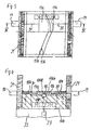
- FIG. 1 a blow molding machine that is well known as such is the For the sake of simplicity, neglecting at least one preform tube providing extrusion or coextrusion head, the associated one Extruders as well as the hose handling device and finished article removal device essentially only the tool 2 shown that consists of an upper mold half 3 and a lower mold half 4.
- the lower one Mold half 4 can, as shown in FIG. 1, alternatively be arranged movably.
- Both mold halves 3, 4 have cavity mold cavities 5, 6, which differ in the from the open position shown closed position to blow a Finished article a previously from a handling device or insert robot from an extrusion or coextrusion head removed and into the mold cavity 6 of the lower mold half 4 insert the preform tube.
- Both the upper and the lower mold halves 3, 4 are made of clamping plates 7, 8 worn.
- the upper mold half 3 is arranged in a carriage 9, which on a Support frame 10 from the blowing station I in a handling station II by means of a on the carriage 9 engaging the traversing drive is linearly movable.
- the upper Mold half 3 is thus on a vertical linear axis 11 and a horizontal one Linear axis 12 movable.
- the carriage 9 is made up of two cylinders Hub device 13 provided.
- the upper half of the mold 3 only by means of the device 13 on the vertical linear axis 11 moved, the blow molding takes place in the closed position and in from the open position shown, the finished article is easily removed from the mold and removed as well as with the upper mold half pivoted into the vertical 3 a handling robot (not shown) sufficient degrees of freedom for insertion has a new preform hose in the lower mold half 4.
- a handling robot not shown
- a locking system For applying the closing or locking force in the closed position of the mold halves 3, 4, a locking system is used, so that a locking unit on the basis of a spar solution.
- To lock are on the bottom Platen 8 locking cylinder 13 and these opposite the upper platen 7 rigid counter bar 14 arranged at Closing of the tool 2 in the closed position, coupling into the locking cylinders 13 engage, after which the locking cylinder 13 the required Apply closing force.
- the in the raised position by means of the swivel device 16 into the vertical swiveling upper mold half 3 is then for Feeding of inserts by hand or automatically using an insertion robot freely accessible.
- the upper mold half 3 is removed from the blowing station I in - as shown - move station II and there, i.e. away from the blowing station I in the illustrated vertical position is pivoted about the pivot axis 15.
- the Mold cavity 5 is thus freely accessible to a robot, a feed system or for manual handling by an operator to keep unhindered Inserts, e.g. B. tabs, in the mold cavity 5.
- the mold half 3 is returned to the blowing station I, in the horizontal Position pivoted according to Fig. 1 and for blowing the finished article the lower mold half 6 lowered and with this with the application of the closing force locked by means of the cylinder 13.
- This interplay can be for anyone Realize machine concepts, especially when the lower one Mold half 3 assigned more than one horizontally movable upper mold half is, the lower mold half 4 then from the respective in the operating position driven upper mold half is covered.
- FIGS. 3 and 4 show another embodiment of a lower mold half 104 with the mold cavity 106 formed therein. This is here separated by two in the area of a narrow radius of the mold cavity 106 opposite one another arranged slide 17a, 17b to the finished article cavity 18 (see FIG. 4) completed, while the slide-free area of the mold cavity 5 of the upper mold half 3 is supplemented, which is shown differently than in Figures 1, 2 with a slidably overlapping and combing the slides 17a, 17b Recess is formed.
- Sub contours 106a, 106b are described in FIG. 3 and 4
- the slides 17a, 17b are coordinated with the insertion process of the robot moved into their closed position shown in FIGS. 3, 4 and prevented thus that the parison tube is in the narrow radius of the cavity 106 can jump out of it.
- the upper mold half has been lowered and the locking system 13, 14 applies the closing force, by shooting one in the lower mold half 4 or 104 integrated blow dome or a blow needle 23 the inflation of that enclosed in the cavity over its entire circumference Preform hose introduced to a finished article.
Abstract
Description
Die Erfindung betrifft eine Blasformmaschine zum Herstellen von abfallarmen 3D-Teilen, umfassend mindestens eine horizontal geteilte Blasform aus einer oberen und einer unteren Formhälfte, die im wesentlichen vertikal in eine Offen- und in eine Schließstellung bewegbar sind, wobei die untere Formhälfte auch seitlich horizontal verschiebbar sein kann, mindestens einen einen Vorformlingsschlauch bereitstellenden Extrusions- bzw. Coextrusionskopf, der von mindestens einem Extruder mit dem Kunststoffmaterial gespeist wird, eine Schlauchhandhabungseinrichtung und eine Fertigartikel-Entnahmeeinrichtung.The invention relates to a blow molding machine for producing low-waste 3D parts, comprising at least one horizontally divided blow mold from an upper one and a lower mold half which is substantially vertical in an open and in a closed position can be moved, the lower mold half also horizontally laterally can be displaceable, at least one preform hose Providing extrusion or coextrusion head, the at least one Extruder is fed with the plastic material, a hose handling device and a finished article removal device.
Das Herstellen von abfallarmen, nahtlosen 3D-Blasformteilen ist eine seit langem bekannte Technik. Hierzu eingesetzte Maschinen weisen in der Regel einen als Wendevorrichtung ausgebildeten Greifer, gegebenenfalls frei programmierbaren sechsachsigen Roboter, zum Einlegen des Vorformlings in ein in dem Blasformwerkzeug eingearbeitetes Formnest bzw. eine Gravur auf. Die nahtlos geblasenen Teile werden hierbei dadurch hergestellt, daß der Vorformling, d.h. der extrudierte Schlauch beim Schließen der Blasform am Umfang nicht abgequetscht wird, sondern vollständig von der Kavität umschlossen ist. Allerdings müssen die beiden Endstücke durch Abquetschen verschlossen werden, um das Aufblasen des Vorformlings durch Nadel- oder Blasdorneinschießen zu ermöglichen. Wie weiterhin durch DE-Z "PLASTVERARBEITER" 44. Jahrgang 1993, Nr. 12, Seiten 44 bis 49 bekanntgeworden, sind als solche hinlänglich bekannte Blasformmaschinen, wie z.B. aus DE 195 19 094 A1 bekannt, dadurch in einen vollautomatischen Herstellungsprozeß eingebunden worden, daß der schlauchartige Vorformling von der Düse des Schlauchkopfes durch einen mechanischen Greifer abgenommen wird, der sich dann nach der Kontur der Kavität verformt. Dieser in der Regel frei programmierbare Sechs-Achsen-Einlegeroboter legt den Vorformling folglich vollautomatisch in die Blasform ein, die wie gemäß der letztgenannten Druckschrift offenbart auf einer vertikalen Schließeinheit aufgespannt ist.The production of low-waste, seamless 3D blow molded parts has been a long time known technology. Machines used for this usually have a Turning device trained gripper, optionally freely programmable six-axis robot, for inserting the preform into one in the blow molding tool incorporated mold nest or an engraving. The seamlessly blown Parts are made by the fact that the preform, i.e. the extruded Hose is not squeezed around the circumference when the blow mold is closed, but instead is completely enclosed by the cavity. However, the two of them End pieces are closed by squeezing to inflate the preform to enable by needle or blow pin insertion. How continue by DE-Z "PLASTVERARBEITER" 44th year 1993, No. 12, pages 44 to 49 have become known as such well-known blow molding machines, such as e.g. known from DE 195 19 094 A1, thereby in a fully automatic manufacturing process been involved that the tubular preform from the Nozzle of the hose head is removed by a mechanical gripper, which then deforms according to the contour of the cavity. This is usually freely programmable Six-axis insertion robots therefore place the preform fully automatically into the blow mold as disclosed according to the latter document is clamped on a vertical clamping unit.
Aus der DE-Z ist es auch bekannt, die Manipulation des Vorformlings durch in der Blasform angeordnete Werkzeugschieber vorzunehmen. Ein solches Einlegeverfahren wird aber hauptsächlich für Blasteile angewendet, die geringe Bauteilkrümmungen aufweisen. Hierbei werden bestimmte, auf der Formtrenn-Ebene liegende Schieber zurückgefahren, wodurch sich verhindern läßt, daß beim Schließen der Blasform diese Bereiche des Vorformlings abgequetscht werden. Nachdem die Schließeinheit das Blasformwerkzeug in üblicher Weise geschlossen hat, werden die Werkzeugschieber wieder vorgefahren und der Vorformling aufgeblasen.From DE-Z it is also known to manipulate the preform in the Blow mold arranged tool slide. Such an insertion process but is mainly used for blow parts, the small component curvatures exhibit. This involves certain, at the mold release level lying slider retracted, which can be prevented that the Closing the blow mold squeezes these areas of the preform. After the clamping unit closes the blow mold in the usual way the tool slides are advanced again and the preform is inflated.
Bei den bekannten Blasformmaschinen hat sich aber gezeigt, daß das Einlegen des Schlauchs bei ungünstigen, sehr engen Radien schwierig oder gar unmöglich ist, weil der Schlauch wieder aus der Kurve herausspringt. Aufgrund des frühzeitigen Kontakts des Schlauchs mit der Formnestkavität der unteren Formhälfte tritt zudem eine nachteilige Abkühlung auf. Schließlich ist das bei den bekannten Blasformmaschinen eingesetzte Schließsystem mit auf Holmen basierenden Schließeinheiten sehr aufwendig, und solche Schließeinheiten eignen sich zudem schlecht für Mehrstationenmaschinen.In the known blow molding machines, however, it has been shown that the insertion the hose with unfavorable, very tight radii difficult or even impossible is because the hose jumps out of the curve again. Because of the early The hose comes into contact with the cavity of the lower mold half also a disadvantageous cooling. After all, this is the case with the known ones Blow molding machines with locking system based on bars Clamping units are very complex, and such clamping units are also suitable bad for multi-station machines.
Der Erfindung liegt daher die Aufgabe zugrunde, eine Blasformmaschine zum Herstellen von abfallarmen 3D-Teilen der eingangs genannten Art mit verbesserter und variablerer Betriebsweise kostengünstig zu schaffen. The invention is therefore based on the object of a blow molding machine Manufacture of low-waste 3D parts of the type mentioned with improved and more variable operation to create inexpensive.
Diese Aufgabe wird erfindungsgemäß dadurch gelöst, daß die obere Formhälfte in der Blasstation in ihrer abgesenkten Betriebslage mit der unteren Formhälfte verriegelbar ist und bei von der unteren Formhälfte abgehobener Lage in eine im wesentlichen senkrechte Position verschwenkbar ist und/oder in horizontaler Ebene linear verfahrbar angeordnet ist. Durch den Einsatz eines bei gattungsgemäßen Blasformmaschinen zum Herstellen von abfallarmen 3D-Teile bisher nicht in Betracht gezogenen, an sich bekannten Verriegelungssysteme zur Aufbringung der Schließ- bzw. Zuhaltekraft bedarf es somit keiner aufwendigen Schließeinheit mehr. Die Erfindung umfaßt damit einerseits die Betriebsweise Verriegeln und ― nach dem Entriegeln ― lineares Verfahren oder Ver- und Entriegeln sowie Verschwenken der oberen Formhälfte und andererseits das Verriegeln und ― nach dem Entriegeln ― sowohl das lineare Verfahren als auch das Verschwenken der oberen Formhälfte.This object is achieved in that the upper mold half in the blow station can be locked in its lowered operating position with the lower mold half is and when lifted from the lower mold half in a substantially vertical position is pivotable and / or in the horizontal plane is arranged linearly movable. Through the use of a generic Blow molding machines for the production of low-waste 3D parts have so far not been considered drawn, known locking systems for applying the Closing or locking force therefore does not require an expensive locking unit more. The invention thus comprises on the one hand the operating mode locking and - after unlocking - linear movement or locking and unlocking as well as pivoting the upper mold half and on the other hand locking and - after unlocking - both the linear method and the pivoting of the upper mold half.
Aufgrund des erfindungsgemäßen Verschwenkens der abgehobenen oberen Formhälfte um 90 ° in die im wesentlichen Senkrechte ist nunmehr diese Formhälfte für einen Einlegeroboter ohne größeren Aufwand erreichbar, was das Zuführen von Einlegeteilen wesentlich erleichtert. Außerdem läßt sich ein großer Zeitvorteil erreichen, da die obere Formhälfte in der gleichen Position steht, wie der den Vorformlingsschlauch einlegende Roboter, der nach dem Verschwenken der Formhälfte einen ausreichenden Freiraum für seine Handhabungsmanipulationen hat. Die obere Formhälfte braucht danach lediglich noch in ihre Betriebslage zurückgeschwenkt und auf die untere Formhäfte abgesenkt zu werden. Demgegenüber verwirklichen bekannte Konzepte eine mehr oder weniger zeitaufwendig manipulierbare untere Formhälfte zur Einlegung des von einem festen Punkt ausgehenden extrudierten Schlauchs.Due to the pivoting of the lifted upper according to the invention Half of the mold by 90 ° into the essentially vertical is now this half of the mold accessible for a loading robot without much effort, which is feeding much easier with inserts. It also saves a lot of time because the upper half of the mold is in the same position as the the preform hose inserting robot, which after the pivoting of the Half of the mold sufficient clearance for its manipulation Has. The upper mold half then only needs to be pivoted back into its operating position and to be lowered to the lower mold halves. In contrast, known concepts implement a more or less time-consuming manipulation lower mold half for inserting the starting point from a fixed point extruded tube.
Wenn die obere Formhälfte zusätzlich linear verfahrbar ist, läßt sich in einfacher Weise ein Mehrstationensystem bzw. ein Betrieb auf sogenannten Radmaschinen verwirklichen, d. h. mehr als zwei Werkzeuge können auf die gleiche Extrusionseinheit zurückgreifen, was insbesondere für die sequentielle Extrusion oder die Coextrusion überhaupt vorteilhaft ist. Die sich in diesem Fall auf zwei Linearachsen bewegende obere Formhälfte ermöglicht eine Betriebsweise, bei der sich die angehobene obere Formhälfte nach wie vor zur Entformung des Fertigartikels benutzen und nach bzw. vor dem Verfahren in eine weitere Station - der sich Folgestationen anschließen können - um 90° in die Vertikale schwenken läßt, um einem Roboter oder Zuführsystem oder Bedienungspersonal das Einlegen von sogenannten Einlegeteilen, z.B. Laschen etc., in einfacher Weise zu ermöglichen.If the upper mold half can also be moved linearly, it can be done in a simpler manner Way a multi-station system or an operation on so-called wheel machines realize, d. H. more than two tools can be on the same extrusion unit fall back on what in particular for sequential extrusion or Coextrusion is beneficial at all. Which in this case are on two linear axes moving upper mold half enables an operation in which the Use the raised upper half of the mold as before to demold the finished article and after or before the procedure in another station - the following stations can connect - swings through 90 ° in the vertical to one Robots or feed system or operating personnel inserting so-called Inserts, e.g. To allow tabs etc. in a simple manner.
Es wird vorgeschlagen, daß ein die obere Formhälfte aufnehmender Verfahrschlitten mit einer Hub-Vorrichtung versehen ist. Diese wird in der Blasstation ausschließlich zum Absenken bzw. Anheben der oberen Formhälfte auf die bzw. von der unteren Formhälfte genutzt. In der Blasstation sind dabei auch solche Formtrennlinien möglich, die von der im wesentlichen horizontalen Teilungsebene abweichen können, da die obere Formhälfte beim Schließvorgang auch mit anderer Bewegungsrichtung geführt werden könnte.It is proposed that a carriage which receives the upper mold half is provided with a lifting device. This is exclusively in the blowing station to lower or raise the upper half of the mold to or from the lower half of the mold. In the blow molding station there are also such dividing lines possible that deviate from the essentially horizontal division level can, because the upper mold half with the closing process with others Direction of movement could be performed.
Um das Verschwenken in die im wesentlichen Senkrechte zu ermöglichen, ist der oberen Formhälfte erfindungsgemäß eine Schwenkeinrichtung zugeordnet, z.B. ein bekannter motorbetriebener Drehantrieb.In order to enable the pivoting into the essentially vertical, the is According to the invention, a swivel device is assigned to the upper mold half, e.g. a well-known motorized rotary drive.
Es empfiehlt sich, daß auf der unteren Formhälfte verschiebbare Verriegelungszylinder und auf der oberen Formhälfte starre Gegenriegel angeordnet sind, und zwar jeweils auf den die Formhälften tragenden Formaufspannplatten. Insbesondere dann, wenn der unteren Formhälfte mehr als eine horizontal verfahrbare obere Formhälfte zugeordnet ist, bedarf es nur einmal einer Bestückung mit den gegenüber den Gegenriegeln hochwertigeren und damit teueren Verriegelungszylindem. It is recommended that locking cylinders slidable on the lower mold half and rigid counter bolts are arranged on the upper mold half, and in each case on the mold mounting plates carrying the mold halves. In particular then when the lower mold half more than a horizontally movable upper Half of the mold is assigned, it only needs to be populated once with the opposite the counter locks of higher quality and therefore more expensive locking cylinders.
Wenn vorzugsweise über der Formnestkavität der unteren Formhälfte zumindest im Bereich von dort engen Radien einander paarweise gegenüberliegend Schieber angeordnet sind, die beim Einlegen eines Vorformlingsschlauches die Artikel-Kavität - gegebenenfalls sukzessive - schließen, läßt sich der Schlauch auch bei sehr engen Radien einlegen, ohne aus der Kavität herauszuspringen. Die obere Formhälfte, die sozusagen einen Topfdeckel für die untere Formhälfte darstellt, besitzt in diesem Fall eine das zumindest eine Schieberpaar formschlüssig einrastend aufnehmende Aussparung. Die für die Schieber notwendigen Antriebe sowie auch die Steuerung sind nicht Bestandteil des Werkzeuges bzw. der Blasform, sondern können in dem die untere Formhälfte aufweisenden Maschinenbett vorgesehen werden. Da nicht die Schieber und deren Antriebe, sondern das Verriegelungssystem die Schließkräfte aufbringt, sind die Schieber mit den Antrieben sehr kostengünstig auszulegen.If at least preferably over the mold cavity of the lower mold half in the area from there narrow radii opposite sliders in pairs are arranged, the article cavity when inserting a preform hose - if necessary successively - close, the hose can also insert very tight radii without jumping out of the cavity. The upper Mold half, which is a kind of pot lid for the lower mold half, in this case has a positively engaging the at least one pair of slides receiving recess. The drives necessary for the slide as well the controls are not part of the tool or blow mold, but can be provided in the machine bed having the lower mold half become. Because not the slides and their drives, but the locking system applies the closing forces, are the slide with the drives very cost effective to interpret.
Ein Vorschlag der Erfindung sieht vor, daß in die Formnestkavität der unteren Formhälfte temperierte Luft eingeblasen wird. Es läßt sich damit ein unzulässiges Abkühlen des Schlauches vermeiden, so daß beim Aufblasprozeß keine dickere Wandung auftritt.A proposal of the invention provides that the mold cavity of the lower Half of the tempered air is blown in. It can be an inadmissible Avoid cooling the tube so that there is no thicker one during the inflation process Wall occurs.
Weitere Merkmale und Vorteile der Erfindung ergeben sich aus den Ansprüchen und der nachfolgenden Beschreibung, in der in den Zeichnungen sehr schematisch dargestellte Ausführungsbeispiele des Gegenstandes der Erfindung näher erläutert sind. Es zeigen:
- Fig. 1
- von einer Blasformmaschine als Einzelheit deren in der aufgefahrenen Betriebsposition dargestellten Formhälften;
- Fig. 2
- eine der Darstellung gemäß Fig. 1 entsprechende Anordnung mit demgegenüber in eine weitere Station verfahrener und in die Senkrechte geschwenkter oberer Formhälfte;
- Fig. 3
- in der Draufsicht eine schematische Darstellung einer anderen Ausführung einer unteren Formhälfte, der im Bereich kritischer Radien der Artikel-Kavität Schieber zugeordnet sind; und
- Fig. 4
- einen Schnitt entlang der Linie IV-IV von Fig. 3.
- Fig. 1
- of a blow molding machine as a detail of the mold halves shown in the open operating position;
- Fig. 2
- an arrangement corresponding to the representation of Figure 1 with the other hand moved into a further station and pivoted into the vertical mold half.
- Fig. 3
- in the plan view a schematic representation of another embodiment of a lower mold half, which slides are assigned in the area of critical radii of the article cavity; and
- Fig. 4
- a section along the line IV-IV of Fig. 3rd
Von einer als solche hinlänglich bekannten Blasformmaschine ist in Fig. 1 der
Einfachheit halber unter Vernachlässigung eines mindestens einen Vorformlingsschlauch
bereitstellenden Extrusions- bzw. Coextrusionskopfes, des diesem zugeordneten
Extruders sowie der Schlauchhandhabungs-Einrichtung und Fertigartikel-Entnahmeeinrichtung
im wesentlichen lediglich das Werkzeug 2 gezeigt, das
aus einer oberen Formhälfte 3 und einer unteren Formhälfte 4 besteht. Die untere
Formhälfte 4 kann wie gemäß Fig. 1 fest, alternativ beweglich angeordnet sein.
Beide Formhälften 3, 4 besitzen Formnestkavitäten 5, 6, die in der abweichend
von der gezeigten Offenstellung geschlossenen Schließstellung zum Blasen eines
Fertigartikels einen zuvor von einem Handhabungsgerät bzw. Einlegeroboter von
einem Extrusions- bzw. Coextrusionskopf abgenommenen und in die Formnestkavität
6 der unteren Formhälfte 4 eingelegten Vorformlingsschlauch einschließen.
Sowohl die obere als auch die untere Formhälfte 3, 4 werden von Formaufspannplatten
7, 8 getragen.In FIG. 1, a blow molding machine that is well known as such is the
For the sake of simplicity, neglecting at least one preform tube
providing extrusion or coextrusion head, the associated one
Extruders as well as the hose handling device and finished article removal device
essentially only the tool 2 shown that
consists of an upper mold half 3 and a lower mold half 4. The lower one
Mold half 4 can, as shown in FIG. 1, alternatively be arranged movably.
Both mold halves 3, 4 have
Die obere Formhälfte 3 ist in einem Schlitten 9 angeordnet, der auf einem
Tragrahmen 10 aus der Blasstation I in eine Handhabungsstation II mittels eines
an den Schlitten 9 angreifenden Verfahrantriebes linear verfahrbar ist. Die obere
Formhälfte 3 ist damit auf einer vertikalen Linearachse 11 und einer horizontalen
Linearachse 12 beweglich. Der Schlitten 9 ist mit einer aus zwei Zylindern bestehenden
Hub-Vorrichtung 13 versehen. Im einfachsten Fall wird die obere Formhälfte
3 mittels der Vorrichtung 13 lediglich auf der vertikalen Linearachse 11 aufund
abbewegt, wobei in der geschlossenen Lage das Blasformen stattfindet und in
der gezeigten Offenstellung ohne weiteres der Fertigartikel entformt und entnommen
werden kann sowie bei in die Senkrechte verschwenkter oberer Formhälfte 3
ein Handhabungsroboter (nicht dargestellt) ausreichende Freiheitsgrade zum Einlegen
eines neuen Vorformlingsschlauchs in die untere Formhälfte 4 hat. Zum
Verschwenken in die Senkrechte und zurück ist der oberen Formhälfte 3 eine
Schwenkeinrichtung 16 zugeordnet.The upper mold half 3 is arranged in a carriage 9, which on a
Zum Aufbringen der Schließ- bzw. Zuhaltekraft in der Schließstellung der Formhälften
3, 4 wird ein Verriegelungssystem verwendet, so daß eine Schließeinheit
auf Basis einer Holmlösung entfallen kann. Zur Verriegelung sind auf der unteren
Formaufspannplatte 8 Verriegelungszylinder 13 und diesen gegenüberliegend auf
der oberen Formaufspannplatte 7 starre Gegenriegel 14 angeordnet, die beim
Zufahren des Werkzeugs 2 in die Schließstellung kuppelnd in die Verriegelungszylinder
13 einrasten, wobei danach die Verriegelungszylinder 13 die erforderliche
Schließkraft aufbringen. Die in der angehobenen Position mittels der Schwenkeinrichtung
16 in die Senkrechte verschwenkbare obere Formhälfte 3 ist dann für das
Zuführen von Einlegeteilen von Hand oder automatisch mittels eines Einlegeroboters
frei zugänglich.For applying the closing or locking force in the closed position of the mold halves
3, 4, a locking system is used, so that a locking unit
on the basis of a spar solution. To lock are on the
Bei der Variante nach Fig. 2 wird die obere Formhälfte 3 aus der Blasstation I in -
wie gezeigt - die Station II verfahren und dort, d.h. entfernt von der Blasstation I in
die dargestellte senkrechte Position um die Schwenkachse 15 verschwenkt. Die
Formnestkavität 5 liegt damit frei zugänglich für einen Roboter, ein Zuführsystem
oder zur manuellen Handhabung durch ein Bedienungspersonal, um ungehindert
Einlegeteile, z. B. Laschen, in die Formnestkavität 5 einzubringen. Sobald das geschehen
ist, wird die Formhälfte 3 in die Blasstation I zurückgefahren, in die horizontale
Position gemäß Fig. 1 geschwenkt und zum Blasen des Fertigartikels auf
die untere Formhälfte 6 abgesenkt und mit dieser unter Aufbringung der Schließkraft
mittels der Zylinder 13 verriegelt. Dieses Wechselspiel läßt sich für beliebige
Maschinenkonzepte verwirklichen, insbesondere auch dann, wenn der unteren
Formhälfte 3 mehr als eine horizontal verfahrbare obere Formhälfte zugeordnet
wird, wobei die untere Formhälfte 4 dann von der jeweiligen in die Betriebsposition
gefahrenen oberen Formhälfte abgedeckelt wird.In the variant according to FIG. 2, the upper mold half 3 is removed from the blowing station I in -
as shown - move station II and there, i.e. away from the blowing station I in
the illustrated vertical position is pivoted about the
Die Figuren 3 und 4 zeigen eine andere Ausführung einer unteren Formhälfte 104
mit der darin ausgebildeten Formnestkavität 106. Diese wird hier durch zwei einander
im Bereich eines engen Radius der Formnestkavität 106 einander gegenüberliegend
angeordnete Schieber 17a, 17b zur fertigen Artikelkavität 18 (vgl. Fig.
4) komplettiert, während der schieberfreie Bereich von der Formnestkavität 5 der
oberen Formhälfte 3 ergänzt wird, die anders als in den Figuren 1, 2 dargestellt
mit einer die Schieber 17a, 17b formschlüssig übergreifenden und einkammemden
Aussparung ausgebildet ist. Zur Komplettierung der Artikelkavität 18 besitzen
die Schieber 17a, 17b jeweils einen Viertelkreis der Artikelkavität 18 entsprechende
Teilkonturen 106a, 106b. Zum Positionieren der Schieber 17a, 17b als Antrieb
eingesetzte Hydraulikzylinder 19 sind über ihre Kolbenstangen 20 mit den Schiebern
17a, 17b verbunden und in X-Y-Richtung in Langlöchern von Traversen 21
des Maschinengestells 22 verstellbar angeordnet. Die Position der Zylinder 19 ist
damit formabhängig einstellbar.FIGS. 3 and 4 show another embodiment of a
Beim Einlegen eines Vorformlingsschlauches in die untere Formnest-Kavität 106
werden mit dem Einlegevorgang des Roboters abgestimmt die Schieber 17a, 17b
in ihre in den Figuren 3, 4 gezeigte geschlossene Position vorgefahren und verhindern
somit, daß der Vorformlingsschlauch in dem engen Radius der Formnestkavität
106 aus dieser herausspringen kann. Sobald die Schieber, deren genaue
Zahl im Einzelfall von den vorhandenen engen Radien bestimmt wird, geschlossen
bzw. zugefahren sind, die obere Formhälfte abgesenkt wurde und das Verriegelungssystem
13, 14 die Schließkraft aufbringt, wird durch Einschießen eines in der
unteren Formhälfte 4 bzw. 104 integrierten Blasdomes bzw. einer Blasnadel 23
das Aufblasen des in dem Formnest über seinen gesamten Umfang eingeschlossenen
Vorformlingsschlauches zu einem Fertigartikel eingeleitet.When inserting a preform tube into the
Claims (7)
- A blow moulding machine for the production of 3D parts with little waste, comprising at least one horizontally split blowing mould (2) consisting of an upper and a lower mould half (3, 4), which can be moved essentially vertically into an open and into a closed position, whereby the lower mould half (4) can also be displaced horizontally sidewards, at least one extrusion or coextrusion head producing preform tube, said head being fed by at least one extruder with the plastic material, a tube handling device and a finished-article removal device,
characterised in that
the upper mould half (3) in a blowing station (1) can be locked in its lowered operating position with the lower mould half (4) and, in a position raised from the lower mould half (4), can be swivelled into an essentially vertical position and/or is arranged linearly conveyable in the horizontal plane. - The blow moulding machine according to claim 1,
characterised in that
a traversing carriage (9) accommodating the upper mould half (3) is provided with a lifting device (13). - The blow moulding machine according to claim 1 or 2,
characterised in that
a swivelling device (16) is assigned to the upper mould half (3). - The blow moulding machine according to any one of claims 1 to 3,
characterised in that
displaceable locking cylinders (13) are arranged on the lower mould half (4) and rigid counter-bolts (14) are arranged on the upper mould half (3). - The blow moulding machine according to any one of claims 1 to 4,
characterised by
slide gates (17a, 17b) arranged in a pair lying opposite one another at least in the region of tight radii above for the mould cavity (6) of the lower mould half (4), said slide gates closing the article cavity (18) when a preform tube is introduced. - The blow moulding machine according to any one of claims 1 to 5,
characterised by
tempered air blown into the mould cavity (6) of the lower mould half (4). - The blow moulding machine according to any one of claims 1 to 6,
characterised in that
more than one horizontally conveyable upper mould half (3) is assigned to the lower mould half (4).
Applications Claiming Priority (2)
| Application Number | Priority Date | Filing Date | Title |
|---|---|---|---|
| DE19922684A DE19922684C2 (en) | 1999-05-18 | 1999-05-18 | Blow molding machine for low-waste blowing |
| DE19922684 | 1999-05-18 |
Publications (3)
| Publication Number | Publication Date |
|---|---|
| EP1053857A2 EP1053857A2 (en) | 2000-11-22 |
| EP1053857A3 EP1053857A3 (en) | 2002-08-14 |
| EP1053857B1 true EP1053857B1 (en) | 2004-05-19 |
Family
ID=7908344
Family Applications (1)
| Application Number | Title | Priority Date | Filing Date |
|---|---|---|---|
| EP00106356A Expired - Lifetime EP1053857B1 (en) | 1999-05-18 | 2000-03-24 | Blow moulding machine for the reduced waste blow moulding |
Country Status (4)
| Country | Link |
|---|---|
| US (1) | US6416313B1 (en) |
| EP (1) | EP1053857B1 (en) |
| AT (1) | ATE267078T1 (en) |
| DE (2) | DE19922684C2 (en) |
Cited By (1)
| Publication number | Priority date | Publication date | Assignee | Title |
|---|---|---|---|---|
| DE10318556A1 (en) * | 2003-04-24 | 2004-11-11 | Sig Technology Ltd. | Method and device for blow molding containers |
Families Citing this family (5)
| Publication number | Priority date | Publication date | Assignee | Title |
|---|---|---|---|---|
| US6833103B2 (en) * | 2002-02-11 | 2004-12-21 | Salflex Polymers Ltd. | Pressless blow molding |
| US6841118B2 (en) * | 2002-02-11 | 2005-01-11 | Salflex Polymers Ltd. | Mold assembly for blow molding plastic articles and method of use |
| AU2003246141A1 (en) * | 2003-05-30 | 2005-01-21 | Lg Electronics, Inc. | Home network system |
| DE102005009276B4 (en) * | 2005-02-25 | 2014-07-10 | Extraplast Maschinen Gmbh | Blow molding system and process for producing hollow bodies |
| CN101579916A (en) * | 2009-06-10 | 2009-11-18 | 张家港市同创机械有限公司 | Three-dimensional hollow blow molding machine and molding process thereof |
Family Cites Families (16)
| Publication number | Priority date | Publication date | Assignee | Title |
|---|---|---|---|---|
| US2692407A (en) * | 1951-08-01 | 1954-10-26 | French Oil Mill Machinery | Molding press with tilting press plate |
| JPS5521240A (en) * | 1978-08-02 | 1980-02-15 | Kiyoshi Takahashi | Production device of hollow, slender synthetic resin with irregular curve |
| JPS5573527A (en) * | 1978-11-29 | 1980-06-03 | Ekuseru Kk | Forming method of synthetic resin pipe of small thickness |
| US4239474A (en) * | 1979-06-29 | 1980-12-16 | Excell Corporation | Apparatus for molding a plastic pipe |
| DE3448497C2 (en) * | 1984-05-08 | 1997-05-22 | Mauser Werke Gmbh | Blow molding machine |
| IT1183969B (en) * | 1985-11-22 | 1987-10-22 | Plast Di Crupi D E C Snc C | EQUIPMENT AND PROCEDURE FOR MANUFACTURING SHAPED ITEMS OF PLASTIC MATERIAL PARTICULARLY FILLING PIPES FOR FUEL TANKS FOR MOTOR VEHICLES |
| US4738612A (en) * | 1986-08-09 | 1988-04-19 | Placo Co., Ltd. | Pivotable blow-molding apparatus for molding hollow articles of synthetic resin |
| CA1273762C (en) * | 1987-06-18 | 1990-09-11 | Blow molding method and apparatus | |
| US5178817A (en) * | 1988-09-06 | 1993-01-12 | Dai Nippon Insatsu K. K. | Stretch blow molding method for manufacturing an expanded bottle |
| CA2003034C (en) * | 1988-11-30 | 1994-05-24 | Akira Ohta | Blow molding mold for forming hollow double-walled product and blow molding apparatus using such mold |
| US5030083A (en) * | 1989-12-28 | 1991-07-09 | Tigers Polymer Corporation | Apparatus for manufacturing a hollow synthetic resin product |
| JP2879459B2 (en) * | 1990-03-12 | 1999-04-05 | 株式会社プラコー | Method and apparatus for supplying blow molding parison to molding cavity of receiving mold in split mold |
| JPH082579B2 (en) * | 1990-09-27 | 1996-01-17 | タイガースポリマー株式会社 | Manufacturing method of hollow synthetic resin products |
| JP3259344B2 (en) * | 1992-07-31 | 2002-02-25 | 豊田合成株式会社 | Blow molding method |
| DE19508525A1 (en) * | 1995-03-10 | 1996-09-12 | Kautex Werke Gmbh | Method and device for producing hollow bodies from thermoplastic material |
| DE19519094C2 (en) * | 1995-05-24 | 1997-03-27 | Koetke Claus Dieter | Process and blow molding machine for the production of elongated hollow plastic bodies |
-
1999
- 1999-05-18 DE DE19922684A patent/DE19922684C2/en not_active Expired - Lifetime
- 1999-11-23 US US09/448,063 patent/US6416313B1/en not_active Expired - Lifetime
-
2000
- 2000-03-24 DE DE50006455T patent/DE50006455D1/en not_active Expired - Fee Related
- 2000-03-24 EP EP00106356A patent/EP1053857B1/en not_active Expired - Lifetime
- 2000-03-24 AT AT00106356T patent/ATE267078T1/en not_active IP Right Cessation
Cited By (1)
| Publication number | Priority date | Publication date | Assignee | Title |
|---|---|---|---|---|
| DE10318556A1 (en) * | 2003-04-24 | 2004-11-11 | Sig Technology Ltd. | Method and device for blow molding containers |
Also Published As
| Publication number | Publication date |
|---|---|
| US6416313B1 (en) | 2002-07-09 |
| DE50006455D1 (en) | 2004-06-24 |
| DE19922684A1 (en) | 2001-01-25 |
| EP1053857A2 (en) | 2000-11-22 |
| ATE267078T1 (en) | 2004-06-15 |
| EP1053857A3 (en) | 2002-08-14 |
| DE19922684C2 (en) | 2001-11-15 |
Similar Documents
| Publication | Publication Date | Title |
|---|---|---|
| EP1673208B1 (en) | Horizontal injection molding machine comprising a turning device | |
| AT409243B (en) | blow molding machine | |
| EP0641279B1 (en) | Blow moulding machine | |
| AT503682B1 (en) | METHOD AND DEVICE FOR PRODUCING COATED PLASTIC MOLDED PARTS | |
| DE2429223A1 (en) | CONTINUOUSLY OPERATING ROTATING DEVICE FOR BLOW-MOUNTING PLASTIC HOLLOW BODIES | |
| DE3216332C2 (en) | Device for producing a three-dimensionally shaped layered body from a compact plastic layer and a foamed-on foam layer | |
| EP0666162A1 (en) | Apparatus for making hollow articles from thermoplastic material by extrusion-blow moulding | |
| EP1053857B1 (en) | Blow moulding machine for the reduced waste blow moulding | |
| EP2909000B1 (en) | Device for producing container products consisting of plastic materials | |
| DE2911143A1 (en) | METHOD AND DEVICE FOR THE PRODUCTION OF HOLLOW BODIES, IN PARTICULAR PLASTIC BOTTLES | |
| EP0810919B1 (en) | Injection moulding machine | |
| DE102010018121B4 (en) | Injection molding machine for producing a plurality of injection molded parts in one cycle | |
| DE102005009276B4 (en) | Blow molding system and process for producing hollow bodies | |
| EP1818157B1 (en) | Extruder | |
| DE19519094C2 (en) | Process and blow molding machine for the production of elongated hollow plastic bodies | |
| EP0893230B1 (en) | Method and apparatus for manufacturing of three dimensional parts and reducing waste material | |
| EP3915744B1 (en) | Battery pressure casting of ceramic hollow bodies | |
| DE2161247C3 (en) | Device for producing hollow bodies | |
| DE102007041776B4 (en) | Method for operating a blow molding device with variable closing device | |
| EP0185110A1 (en) | Blow-moulding installation for the manufacture of hollow bodies from plastic material | |
| EP0734837A1 (en) | Apparatus for transporting a parison from an annular die to a blow mould of a blow moulding machine | |
| DE3434582C1 (en) | Machine for producing blow-moulded plastics hollow bodies | |
| EP2614949B1 (en) | Blow-moulding system and method for the blow-moulding of hollow bodies | |
| EP1048435A1 (en) | Injection blow moulding process and device | |
| WO2024068807A1 (en) | Device for producing hollow bodies |
Legal Events
| Date | Code | Title | Description |
|---|---|---|---|
| PUAI | Public reference made under article 153(3) epc to a published international application that has entered the european phase |
Free format text: ORIGINAL CODE: 0009012 |
|
| AK | Designated contracting states |
Kind code of ref document: A2 Designated state(s): AT BE CH CY DE DK ES FI FR GB GR IE IT LI LU MC NL PT SE |
|
| AX | Request for extension of the european patent |
Free format text: AL;LT;LV;MK;RO;SI |
|
| RAP1 | Party data changed (applicant data changed or rights of an application transferred) |
Owner name: SIG KAUTEX GMBH & CO.KG |
|
| PUAL | Search report despatched |
Free format text: ORIGINAL CODE: 0009013 |
|
| AK | Designated contracting states |
Kind code of ref document: A3 Designated state(s): AT BE CH CY DE DK ES FI FR GB GR IE IT LI LU MC NL PT SE |
|
| AX | Request for extension of the european patent |
Free format text: AL;LT;LV;MK;RO;SI |
|
| 17P | Request for examination filed |
Effective date: 20030201 |
|
| 17Q | First examination report despatched |
Effective date: 20030317 |
|
| AKX | Designation fees paid |
Designated state(s): AT BE CH CY DE DK ES FI FR GB GR IE IT LI LU MC NL PT SE |
|
| GRAP | Despatch of communication of intention to grant a patent |
Free format text: ORIGINAL CODE: EPIDOSNIGR1 |
|
| GRAS | Grant fee paid |
Free format text: ORIGINAL CODE: EPIDOSNIGR3 |
|
| GRAA | (expected) grant |
Free format text: ORIGINAL CODE: 0009210 |
|
| AK | Designated contracting states |
Kind code of ref document: B1 Designated state(s): AT BE CH CY DE DK ES FI FR GB GR IE IT LI LU MC NL PT SE |
|
| PG25 | Lapsed in a contracting state [announced via postgrant information from national office to epo] |
Ref country code: IT Free format text: LAPSE BECAUSE OF FAILURE TO SUBMIT A TRANSLATION OF THE DESCRIPTION OR TO PAY THE FEE WITHIN THE PRESCRIBED TIME-LIMIT;WARNING: LAPSES OF ITALIAN PATENTS WITH EFFECTIVE DATE BEFORE 2007 MAY HAVE OCCURRED AT ANY TIME BEFORE 2007. THE CORRECT EFFECTIVE DATE MAY BE DIFFERENT FROM THE ONE RECORDED. Effective date: 20040519 Ref country code: FR Free format text: LAPSE BECAUSE OF FAILURE TO SUBMIT A TRANSLATION OF THE DESCRIPTION OR TO PAY THE FEE WITHIN THE PRESCRIBED TIME-LIMIT Effective date: 20040519 Ref country code: FI Free format text: LAPSE BECAUSE OF FAILURE TO SUBMIT A TRANSLATION OF THE DESCRIPTION OR TO PAY THE FEE WITHIN THE PRESCRIBED TIME-LIMIT Effective date: 20040519 Ref country code: NL Free format text: LAPSE BECAUSE OF FAILURE TO SUBMIT A TRANSLATION OF THE DESCRIPTION OR TO PAY THE FEE WITHIN THE PRESCRIBED TIME-LIMIT Effective date: 20040519 Ref country code: GB Free format text: LAPSE BECAUSE OF FAILURE TO SUBMIT A TRANSLATION OF THE DESCRIPTION OR TO PAY THE FEE WITHIN THE PRESCRIBED TIME-LIMIT Effective date: 20040519 Ref country code: IE Free format text: LAPSE BECAUSE OF FAILURE TO SUBMIT A TRANSLATION OF THE DESCRIPTION OR TO PAY THE FEE WITHIN THE PRESCRIBED TIME-LIMIT Effective date: 20040519 |
|
| REG | Reference to a national code |
Ref country code: GB Ref legal event code: FG4D Free format text: NOT ENGLISH |
|
| REG | Reference to a national code |
Ref country code: CH Ref legal event code: EP |
|
| REG | Reference to a national code |
Ref country code: IE Ref legal event code: FG4D Free format text: GERMAN |
|
| REF | Corresponds to: |
Ref document number: 50006455 Country of ref document: DE Date of ref document: 20040624 Kind code of ref document: P |
|
| PG25 | Lapsed in a contracting state [announced via postgrant information from national office to epo] |
Ref country code: DK Free format text: LAPSE BECAUSE OF FAILURE TO SUBMIT A TRANSLATION OF THE DESCRIPTION OR TO PAY THE FEE WITHIN THE PRESCRIBED TIME-LIMIT Effective date: 20040819 Ref country code: SE Free format text: LAPSE BECAUSE OF FAILURE TO SUBMIT A TRANSLATION OF THE DESCRIPTION OR TO PAY THE FEE WITHIN THE PRESCRIBED TIME-LIMIT Effective date: 20040819 Ref country code: GR Free format text: LAPSE BECAUSE OF FAILURE TO SUBMIT A TRANSLATION OF THE DESCRIPTION OR TO PAY THE FEE WITHIN THE PRESCRIBED TIME-LIMIT Effective date: 20040819 |
|
| PG25 | Lapsed in a contracting state [announced via postgrant information from national office to epo] |
Ref country code: ES Free format text: LAPSE BECAUSE OF FAILURE TO SUBMIT A TRANSLATION OF THE DESCRIPTION OR TO PAY THE FEE WITHIN THE PRESCRIBED TIME-LIMIT Effective date: 20040830 |
|
| NLV1 | Nl: lapsed or annulled due to failure to fulfill the requirements of art. 29p and 29m of the patents act | ||
| GBV | Gb: ep patent (uk) treated as always having been void in accordance with gb section 77(7)/1977 [no translation filed] |
Effective date: 20040519 |
|
| REG | Reference to a national code |
Ref country code: IE Ref legal event code: FD4D |
|
| PG25 | Lapsed in a contracting state [announced via postgrant information from national office to epo] |
Ref country code: LU Free format text: LAPSE BECAUSE OF NON-PAYMENT OF DUE FEES Effective date: 20050324 Ref country code: AT Free format text: LAPSE BECAUSE OF NON-PAYMENT OF DUE FEES Effective date: 20050324 Ref country code: CY Free format text: LAPSE BECAUSE OF FAILURE TO SUBMIT A TRANSLATION OF THE DESCRIPTION OR TO PAY THE FEE WITHIN THE PRESCRIBED TIME-LIMIT Effective date: 20050324 |
|
| PLBE | No opposition filed within time limit |
Free format text: ORIGINAL CODE: 0009261 |
|
| STAA | Information on the status of an ep patent application or granted ep patent |
Free format text: STATUS: NO OPPOSITION FILED WITHIN TIME LIMIT |
|
| PG25 | Lapsed in a contracting state [announced via postgrant information from national office to epo] |
Ref country code: MC Free format text: LAPSE BECAUSE OF NON-PAYMENT OF DUE FEES Effective date: 20050331 Ref country code: BE Free format text: LAPSE BECAUSE OF NON-PAYMENT OF DUE FEES Effective date: 20050331 Ref country code: CH Free format text: LAPSE BECAUSE OF NON-PAYMENT OF DUE FEES Effective date: 20050331 Ref country code: LI Free format text: LAPSE BECAUSE OF NON-PAYMENT OF DUE FEES Effective date: 20050331 |
|
| 26N | No opposition filed |
Effective date: 20050222 |
|
| EN | Fr: translation not filed | ||
| BERE | Be: lapsed |
Owner name: *SIG KAUTEX G.M.B.H. & CO. KG Effective date: 20050331 |
|
| PG25 | Lapsed in a contracting state [announced via postgrant information from national office to epo] |
Ref country code: DE Free format text: LAPSE BECAUSE OF NON-PAYMENT OF DUE FEES Effective date: 20051001 |
|
| REG | Reference to a national code |
Ref country code: CH Ref legal event code: PL |
|
| BERE | Be: lapsed |
Owner name: *SIG KAUTEX G.M.B.H. & CO. K.G. Effective date: 20050331 |
|
| PG25 | Lapsed in a contracting state [announced via postgrant information from national office to epo] |
Ref country code: PT Free format text: LAPSE BECAUSE OF NON-PAYMENT OF DUE FEES Effective date: 20041019 |