EP3909633B1 - Chambre d'humidification avec un élément de mélange comprenant des microstructures - Google Patents
Chambre d'humidification avec un élément de mélange comprenant des microstructures Download PDFInfo
- Publication number
- EP3909633B1 EP3909633B1 EP21169700.8A EP21169700A EP3909633B1 EP 3909633 B1 EP3909633 B1 EP 3909633B1 EP 21169700 A EP21169700 A EP 21169700A EP 3909633 B1 EP3909633 B1 EP 3909633B1
- Authority
- EP
- European Patent Office
- Prior art keywords
- humidification chamber
- microstructures
- tube
- water
- liquid
- Prior art date
- Legal status (The legal status is an assumption and is not a legal conclusion. Google has not performed a legal analysis and makes no representation as to the accuracy of the status listed.)
- Active
Links
- 238000002156 mixing Methods 0.000 title claims description 38
- XLYOFNOQVPJJNP-UHFFFAOYSA-N water Substances O XLYOFNOQVPJJNP-UHFFFAOYSA-N 0.000 claims description 163
- 239000007788 liquid Substances 0.000 claims description 123
- 239000007789 gas Substances 0.000 claims description 81
- 230000009977 dual effect Effects 0.000 claims description 17
- 239000007791 liquid phase Substances 0.000 claims description 8
- 230000004044 response Effects 0.000 claims description 7
- 239000007792 gaseous phase Substances 0.000 claims description 5
- 239000006185 dispersion Substances 0.000 claims description 2
- 239000000463 material Substances 0.000 description 122
- 238000000034 method Methods 0.000 description 50
- 238000001704 evaporation Methods 0.000 description 39
- 230000008020 evaporation Effects 0.000 description 39
- 239000003570 air Substances 0.000 description 36
- 238000010438 heat treatment Methods 0.000 description 31
- 239000003795 chemical substances by application Substances 0.000 description 25
- 238000005520 cutting process Methods 0.000 description 25
- 229910052751 metal Inorganic materials 0.000 description 20
- 239000002184 metal Substances 0.000 description 20
- 229920003023 plastic Polymers 0.000 description 20
- 239000004033 plastic Substances 0.000 description 19
- 230000001965 increasing effect Effects 0.000 description 17
- 239000004094 surface-active agent Substances 0.000 description 17
- 230000003434 inspiratory effect Effects 0.000 description 16
- 229920000642 polymer Polymers 0.000 description 16
- 238000004519 manufacturing process Methods 0.000 description 15
- 239000000758 substrate Substances 0.000 description 13
- 230000029058 respiratory gaseous exchange Effects 0.000 description 12
- 239000000654 additive Substances 0.000 description 10
- 229910052782 aluminium Inorganic materials 0.000 description 10
- XAGFODPZIPBFFR-UHFFFAOYSA-N aluminium Chemical compound [Al] XAGFODPZIPBFFR-UHFFFAOYSA-N 0.000 description 10
- 238000001125 extrusion Methods 0.000 description 10
- 230000001788 irregular Effects 0.000 description 10
- 239000002904 solvent Substances 0.000 description 10
- 230000007480 spreading Effects 0.000 description 10
- 238000003892 spreading Methods 0.000 description 10
- 238000012546 transfer Methods 0.000 description 10
- -1 Polypropylene Polymers 0.000 description 9
- 238000004049 embossing Methods 0.000 description 9
- 239000000523 sample Substances 0.000 description 9
- 238000009736 wetting Methods 0.000 description 9
- NIXOWILDQLNWCW-UHFFFAOYSA-N acrylic acid group Chemical group C(C=C)(=O)O NIXOWILDQLNWCW-UHFFFAOYSA-N 0.000 description 8
- 230000000996 additive effect Effects 0.000 description 8
- 230000015572 biosynthetic process Effects 0.000 description 8
- 239000004594 Masterbatch (MB) Substances 0.000 description 7
- 239000012530 fluid Substances 0.000 description 7
- 239000007787 solid Substances 0.000 description 7
- ZMXDDKWLCZADIW-UHFFFAOYSA-N N,N-Dimethylformamide Chemical compound CN(C)C=O ZMXDDKWLCZADIW-UHFFFAOYSA-N 0.000 description 6
- 238000000576 coating method Methods 0.000 description 6
- 238000011049 filling Methods 0.000 description 6
- 230000008569 process Effects 0.000 description 6
- 239000010409 thin film Substances 0.000 description 6
- 229920010126 Linear Low Density Polyethylene (LLDPE) Polymers 0.000 description 5
- 238000009833 condensation Methods 0.000 description 5
- 230000005494 condensation Effects 0.000 description 5
- 230000008878 coupling Effects 0.000 description 5
- 238000010168 coupling process Methods 0.000 description 5
- 238000005859 coupling reaction Methods 0.000 description 5
- 230000007423 decrease Effects 0.000 description 5
- 238000006073 displacement reaction Methods 0.000 description 5
- 239000010408 film Substances 0.000 description 5
- 239000012528 membrane Substances 0.000 description 5
- 239000000203 mixture Substances 0.000 description 5
- 239000000126 substance Substances 0.000 description 5
- 238000011282 treatment Methods 0.000 description 5
- VBICKXHEKHSIBG-UHFFFAOYSA-N 1-monostearoylglycerol Chemical compound CCCCCCCCCCCCCCCCCC(=O)OCC(O)CO VBICKXHEKHSIBG-UHFFFAOYSA-N 0.000 description 4
- RYGMFSIKBFXOCR-UHFFFAOYSA-N Copper Chemical compound [Cu] RYGMFSIKBFXOCR-UHFFFAOYSA-N 0.000 description 4
- WYURNTSHIVDZCO-UHFFFAOYSA-N Tetrahydrofuran Chemical compound C1CCOC1 WYURNTSHIVDZCO-UHFFFAOYSA-N 0.000 description 4
- 230000009471 action Effects 0.000 description 4
- 239000000853 adhesive Substances 0.000 description 4
- 230000001070 adhesive effect Effects 0.000 description 4
- 239000011248 coating agent Substances 0.000 description 4
- 238000004891 communication Methods 0.000 description 4
- 229910052802 copper Inorganic materials 0.000 description 4
- 239000010949 copper Substances 0.000 description 4
- 239000011521 glass Substances 0.000 description 4
- 230000005484 gravity Effects 0.000 description 4
- 238000009499 grossing Methods 0.000 description 4
- 230000003993 interaction Effects 0.000 description 4
- 238000005259 measurement Methods 0.000 description 4
- 150000002739 metals Chemical class 0.000 description 4
- 230000003287 optical effect Effects 0.000 description 4
- 239000002245 particle Substances 0.000 description 4
- 241001631457 Cannula Species 0.000 description 3
- OKKJLVBELUTLKV-UHFFFAOYSA-N Methanol Chemical compound OC OKKJLVBELUTLKV-UHFFFAOYSA-N 0.000 description 3
- 239000004743 Polypropylene Substances 0.000 description 3
- 230000008901 benefit Effects 0.000 description 3
- 238000010276 construction Methods 0.000 description 3
- 238000013461 design Methods 0.000 description 3
- 230000000694 effects Effects 0.000 description 3
- 230000008030 elimination Effects 0.000 description 3
- 238000003379 elimination reaction Methods 0.000 description 3
- 238000001746 injection moulding Methods 0.000 description 3
- 230000007246 mechanism Effects 0.000 description 3
- 230000004048 modification Effects 0.000 description 3
- 238000012986 modification Methods 0.000 description 3
- 239000012778 molding material Substances 0.000 description 3
- 239000013500 performance material Substances 0.000 description 3
- 229920000515 polycarbonate Polymers 0.000 description 3
- 229920001155 polypropylene Polymers 0.000 description 3
- 230000005855 radiation Effects 0.000 description 3
- 238000002644 respiratory therapy Methods 0.000 description 3
- 230000003746 surface roughness Effects 0.000 description 3
- 238000012876 topography Methods 0.000 description 3
- 206010002091 Anaesthesia Diseases 0.000 description 2
- 229910001369 Brass Inorganic materials 0.000 description 2
- OKTJSMMVPCPJKN-UHFFFAOYSA-N Carbon Chemical compound [C] OKTJSMMVPCPJKN-UHFFFAOYSA-N 0.000 description 2
- LFQSCWFLJHTTHZ-UHFFFAOYSA-N Ethanol Chemical compound CCO LFQSCWFLJHTTHZ-UHFFFAOYSA-N 0.000 description 2
- PXHVJJICTQNCMI-UHFFFAOYSA-N Nickel Chemical compound [Ni] PXHVJJICTQNCMI-UHFFFAOYSA-N 0.000 description 2
- 239000004677 Nylon Substances 0.000 description 2
- 239000004952 Polyamide Substances 0.000 description 2
- 239000004698 Polyethylene Substances 0.000 description 2
- XUIMIQQOPSSXEZ-UHFFFAOYSA-N Silicon Chemical group [Si] XUIMIQQOPSSXEZ-UHFFFAOYSA-N 0.000 description 2
- GWEVSGVZZGPLCZ-UHFFFAOYSA-N Titan oxide Chemical compound O=[Ti]=O GWEVSGVZZGPLCZ-UHFFFAOYSA-N 0.000 description 2
- 239000012080 ambient air Substances 0.000 description 2
- 230000037005 anaesthesia Effects 0.000 description 2
- 230000004888 barrier function Effects 0.000 description 2
- 239000011324 bead Substances 0.000 description 2
- 239000010951 brass Substances 0.000 description 2
- 238000005266 casting Methods 0.000 description 2
- 239000003093 cationic surfactant Substances 0.000 description 2
- 230000000295 complement effect Effects 0.000 description 2
- 238000000748 compression moulding Methods 0.000 description 2
- 239000004020 conductor Substances 0.000 description 2
- 230000001419 dependent effect Effects 0.000 description 2
- 230000002708 enhancing effect Effects 0.000 description 2
- 239000011888 foil Substances 0.000 description 2
- 230000006870 function Effects 0.000 description 2
- PCHJSUWPFVWCPO-UHFFFAOYSA-N gold Chemical compound [Au] PCHJSUWPFVWCPO-UHFFFAOYSA-N 0.000 description 2
- 229910052737 gold Inorganic materials 0.000 description 2
- 239000010931 gold Substances 0.000 description 2
- 239000008187 granular material Substances 0.000 description 2
- 238000010348 incorporation Methods 0.000 description 2
- 238000009413 insulation Methods 0.000 description 2
- 229920000092 linear low density polyethylene Polymers 0.000 description 2
- 239000004707 linear low-density polyethylene Substances 0.000 description 2
- 229920001684 low density polyethylene Polymers 0.000 description 2
- 239000004702 low-density polyethylene Substances 0.000 description 2
- 230000007257 malfunction Effects 0.000 description 2
- 238000002715 modification method Methods 0.000 description 2
- 229920001778 nylon Polymers 0.000 description 2
- 229920002647 polyamide Polymers 0.000 description 2
- 239000004417 polycarbonate Substances 0.000 description 2
- 229920000728 polyester Polymers 0.000 description 2
- 229920000570 polyether Polymers 0.000 description 2
- 229920000573 polyethylene Polymers 0.000 description 2
- 229920000139 polyethylene terephthalate Polymers 0.000 description 2
- 239000005020 polyethylene terephthalate Substances 0.000 description 2
- 229920001296 polysiloxane Polymers 0.000 description 2
- 229920002635 polyurethane Polymers 0.000 description 2
- 239000004814 polyurethane Substances 0.000 description 2
- 230000009467 reduction Effects 0.000 description 2
- 229920005989 resin Polymers 0.000 description 2
- 239000011347 resin Substances 0.000 description 2
- 230000000241 respiratory effect Effects 0.000 description 2
- 238000007789 sealing Methods 0.000 description 2
- YLQBMQCUIZJEEH-UHFFFAOYSA-N tetrahydrofuran Natural products C=1C=COC=1 YLQBMQCUIZJEEH-UHFFFAOYSA-N 0.000 description 2
- 230000007704 transition Effects 0.000 description 2
- 238000009834 vaporization Methods 0.000 description 2
- 230000008016 vaporization Effects 0.000 description 2
- 238000003466 welding Methods 0.000 description 2
- JNYAEWCLZODPBN-JGWLITMVSA-N (2r,3r,4s)-2-[(1r)-1,2-dihydroxyethyl]oxolane-3,4-diol Chemical class OC[C@@H](O)[C@H]1OC[C@H](O)[C@H]1O JNYAEWCLZODPBN-JGWLITMVSA-N 0.000 description 1
- ZZNDQCACFUJAKJ-UHFFFAOYSA-N 1-phenyltridecan-1-one Chemical compound CCCCCCCCCCCCC(=O)C1=CC=CC=C1 ZZNDQCACFUJAKJ-UHFFFAOYSA-N 0.000 description 1
- FRWYFWZENXDZMU-UHFFFAOYSA-N 2-iodoquinoline Chemical compound C1=CC=CC2=NC(I)=CC=C21 FRWYFWZENXDZMU-UHFFFAOYSA-N 0.000 description 1
- 229920008132 Arnitel® VT3108 Polymers 0.000 description 1
- 229910052582 BN Inorganic materials 0.000 description 1
- 229920001342 Bakelite® Polymers 0.000 description 1
- PZNSFCLAULLKQX-UHFFFAOYSA-N Boron nitride Chemical compound N#B PZNSFCLAULLKQX-UHFFFAOYSA-N 0.000 description 1
- 229920000049 Carbon (fiber) Polymers 0.000 description 1
- 241000579895 Chlorostilbon Species 0.000 description 1
- 241000272201 Columbiformes Species 0.000 description 1
- 239000004593 Epoxy Substances 0.000 description 1
- 239000004425 Makrolon Substances 0.000 description 1
- CBENFWSGALASAD-UHFFFAOYSA-N Ozone Chemical compound [O-][O+]=O CBENFWSGALASAD-UHFFFAOYSA-N 0.000 description 1
- 229920012485 Plasticized Polyvinyl chloride Polymers 0.000 description 1
- 229920000034 Plastomer Polymers 0.000 description 1
- 229920002614 Polyether block amide Polymers 0.000 description 1
- 239000004721 Polyphenylene oxide Substances 0.000 description 1
- BQCADISMDOOEFD-UHFFFAOYSA-N Silver Chemical compound [Ag] BQCADISMDOOEFD-UHFFFAOYSA-N 0.000 description 1
- 210000000683 abdominal cavity Anatomy 0.000 description 1
- 230000002745 absorbent Effects 0.000 description 1
- 239000002250 absorbent Substances 0.000 description 1
- 230000001133 acceleration Effects 0.000 description 1
- 239000002253 acid Substances 0.000 description 1
- 150000007513 acids Chemical class 0.000 description 1
- XECAHXYUAAWDEL-UHFFFAOYSA-N acrylonitrile butadiene styrene Chemical compound C=CC=C.C=CC#N.C=CC1=CC=CC=C1 XECAHXYUAAWDEL-UHFFFAOYSA-N 0.000 description 1
- 239000004676 acrylonitrile butadiene styrene Substances 0.000 description 1
- 229920000122 acrylonitrile butadiene styrene Polymers 0.000 description 1
- 239000004480 active ingredient Substances 0.000 description 1
- 238000004026 adhesive bonding Methods 0.000 description 1
- 229920000615 alginic acid Polymers 0.000 description 1
- 235000010443 alginic acid Nutrition 0.000 description 1
- 150000001412 amines Chemical class 0.000 description 1
- 229920006125 amorphous polymer Polymers 0.000 description 1
- 125000000129 anionic group Chemical group 0.000 description 1
- 239000003945 anionic surfactant Substances 0.000 description 1
- 210000003050 axon Anatomy 0.000 description 1
- 239000004637 bakelite Substances 0.000 description 1
- LTPBRCUWZOMYOC-UHFFFAOYSA-N beryllium oxide Inorganic materials O=[Be] LTPBRCUWZOMYOC-UHFFFAOYSA-N 0.000 description 1
- 230000036760 body temperature Effects 0.000 description 1
- 239000006229 carbon black Substances 0.000 description 1
- 239000004917 carbon fiber Substances 0.000 description 1
- 229910021393 carbon nanotube Inorganic materials 0.000 description 1
- 239000002041 carbon nanotube Substances 0.000 description 1
- 125000002091 cationic group Chemical group 0.000 description 1
- 239000000919 ceramic Substances 0.000 description 1
- 229910010293 ceramic material Inorganic materials 0.000 description 1
- 230000008859 change Effects 0.000 description 1
- 239000002131 composite material Substances 0.000 description 1
- 239000011231 conductive filler Substances 0.000 description 1
- 229920001940 conductive polymer Polymers 0.000 description 1
- 229920001577 copolymer Polymers 0.000 description 1
- PMHQVHHXPFUNSP-UHFFFAOYSA-M copper(1+);methylsulfanylmethane;bromide Chemical compound Br[Cu].CSC PMHQVHHXPFUNSP-UHFFFAOYSA-M 0.000 description 1
- 239000013078 crystal Substances 0.000 description 1
- 230000001627 detrimental effect Effects 0.000 description 1
- 150000005690 diesters Chemical class 0.000 description 1
- 230000003292 diminished effect Effects 0.000 description 1
- KPUWHANPEXNPJT-UHFFFAOYSA-N disiloxane Chemical class [SiH3]O[SiH3] KPUWHANPEXNPJT-UHFFFAOYSA-N 0.000 description 1
- 238000001035 drying Methods 0.000 description 1
- 238000010894 electron beam technology Methods 0.000 description 1
- 229910052876 emerald Inorganic materials 0.000 description 1
- 239000010976 emerald Substances 0.000 description 1
- 229920006351 engineering plastic Polymers 0.000 description 1
- 230000007613 environmental effect Effects 0.000 description 1
- 239000005038 ethylene vinyl acetate Substances 0.000 description 1
- 150000002191 fatty alcohols Chemical class 0.000 description 1
- 229920002457 flexible plastic Polymers 0.000 description 1
- 238000007667 floating Methods 0.000 description 1
- 239000002223 garnet Substances 0.000 description 1
- 230000009477 glass transition Effects 0.000 description 1
- YQEMORVAKMFKLG-UHFFFAOYSA-N glycerine monostearate Natural products CCCCCCCCCCCCCCCCCC(=O)OC(CO)CO YQEMORVAKMFKLG-UHFFFAOYSA-N 0.000 description 1
- SVUQHVRAGMNPLW-UHFFFAOYSA-N glycerol monostearate Natural products CCCCCCCCCCCCCCCCC(=O)OCC(O)CO SVUQHVRAGMNPLW-UHFFFAOYSA-N 0.000 description 1
- 229910002804 graphite Inorganic materials 0.000 description 1
- 239000010439 graphite Substances 0.000 description 1
- GPRLSGONYQIRFK-UHFFFAOYSA-N hydron Chemical compound [H+] GPRLSGONYQIRFK-UHFFFAOYSA-N 0.000 description 1
- 229920001477 hydrophilic polymer Polymers 0.000 description 1
- 230000006872 improvement Effects 0.000 description 1
- 239000004615 ingredient Substances 0.000 description 1
- 238000010884 ion-beam technique Methods 0.000 description 1
- 238000005304 joining Methods 0.000 description 1
- 238000002032 lab-on-a-chip Methods 0.000 description 1
- 238000003754 machining Methods 0.000 description 1
- 239000011159 matrix material Substances 0.000 description 1
- 229920002529 medical grade silicone Polymers 0.000 description 1
- 239000007769 metal material Substances 0.000 description 1
- 239000002991 molded plastic Substances 0.000 description 1
- 238000000465 moulding Methods 0.000 description 1
- 229910052759 nickel Inorganic materials 0.000 description 1
- 239000002736 nonionic surfactant Substances 0.000 description 1
- 229920000847 nonoxynol Polymers 0.000 description 1
- 239000003921 oil Substances 0.000 description 1
- 230000003647 oxidation Effects 0.000 description 1
- 238000007254 oxidation reaction Methods 0.000 description 1
- TWNQGVIAIRXVLR-UHFFFAOYSA-N oxo(oxoalumanyloxy)alumane Chemical compound O=[Al]O[Al]=O TWNQGVIAIRXVLR-UHFFFAOYSA-N 0.000 description 1
- 239000008188 pellet Substances 0.000 description 1
- 230000035699 permeability Effects 0.000 description 1
- 239000012071 phase Substances 0.000 description 1
- 230000002186 photoactivation Effects 0.000 description 1
- 238000000053 physical method Methods 0.000 description 1
- 239000000049 pigment Substances 0.000 description 1
- 235000013550 pizza Nutrition 0.000 description 1
- 229920003229 poly(methyl methacrylate) Polymers 0.000 description 1
- 229920002338 polyhydroxyethylmethacrylate Polymers 0.000 description 1
- 239000004926 polymethyl methacrylate Substances 0.000 description 1
- 229920000098 polyolefin Polymers 0.000 description 1
- 239000004800 polyvinyl chloride Substances 0.000 description 1
- 239000002243 precursor Substances 0.000 description 1
- 238000012545 processing Methods 0.000 description 1
- 238000011084 recovery Methods 0.000 description 1
- 230000001105 regulatory effect Effects 0.000 description 1
- 230000002787 reinforcement Effects 0.000 description 1
- 230000003014 reinforcing effect Effects 0.000 description 1
- 230000000630 rising effect Effects 0.000 description 1
- 229920006126 semicrystalline polymer Polymers 0.000 description 1
- 238000000926 separation method Methods 0.000 description 1
- 229910052710 silicon Inorganic materials 0.000 description 1
- 239000010703 silicon Substances 0.000 description 1
- 229920002379 silicone rubber Polymers 0.000 description 1
- 239000004945 silicone rubber Substances 0.000 description 1
- 229910052709 silver Inorganic materials 0.000 description 1
- 239000004332 silver Substances 0.000 description 1
- 159000000000 sodium salts Chemical class 0.000 description 1
- 230000003381 solubilizing effect Effects 0.000 description 1
- 238000001179 sorption measurement Methods 0.000 description 1
- 230000003068 static effect Effects 0.000 description 1
- 238000004381 surface treatment Methods 0.000 description 1
- 238000001356 surgical procedure Methods 0.000 description 1
- 239000000725 suspension Substances 0.000 description 1
- 238000012360 testing method Methods 0.000 description 1
- 239000012808 vapor phase Substances 0.000 description 1
- 229920002554 vinyl polymer Polymers 0.000 description 1
- 210000001835 viscera Anatomy 0.000 description 1
- 239000000080 wetting agent Substances 0.000 description 1
- 238000004804 winding Methods 0.000 description 1
Images


Classifications
-
- A—HUMAN NECESSITIES
- A61—MEDICAL OR VETERINARY SCIENCE; HYGIENE
- A61M—DEVICES FOR INTRODUCING MEDIA INTO, OR ONTO, THE BODY; DEVICES FOR TRANSDUCING BODY MEDIA OR FOR TAKING MEDIA FROM THE BODY; DEVICES FOR PRODUCING OR ENDING SLEEP OR STUPOR
- A61M16/00—Devices for influencing the respiratory system of patients by gas treatment, e.g. mouth-to-mouth respiration; Tracheal tubes
- A61M16/10—Preparation of respiratory gases or vapours
- A61M16/14—Preparation of respiratory gases or vapours by mixing different fluids, one of them being in a liquid phase
- A61M16/16—Devices to humidify the respiration air
-
- A—HUMAN NECESSITIES
- A61—MEDICAL OR VETERINARY SCIENCE; HYGIENE
- A61M—DEVICES FOR INTRODUCING MEDIA INTO, OR ONTO, THE BODY; DEVICES FOR TRANSDUCING BODY MEDIA OR FOR TAKING MEDIA FROM THE BODY; DEVICES FOR PRODUCING OR ENDING SLEEP OR STUPOR
- A61M16/00—Devices for influencing the respiratory system of patients by gas treatment, e.g. mouth-to-mouth respiration; Tracheal tubes
- A61M16/08—Bellows; Connecting tubes ; Water traps; Patient circuits
- A61M16/0808—Condensation traps
-
- A—HUMAN NECESSITIES
- A61—MEDICAL OR VETERINARY SCIENCE; HYGIENE
- A61M—DEVICES FOR INTRODUCING MEDIA INTO, OR ONTO, THE BODY; DEVICES FOR TRANSDUCING BODY MEDIA OR FOR TAKING MEDIA FROM THE BODY; DEVICES FOR PRODUCING OR ENDING SLEEP OR STUPOR
- A61M16/00—Devices for influencing the respiratory system of patients by gas treatment, e.g. mouth-to-mouth respiration; Tracheal tubes
- A61M16/021—Devices for influencing the respiratory system of patients by gas treatment, e.g. mouth-to-mouth respiration; Tracheal tubes operated by electrical means
- A61M16/022—Control means therefor
- A61M16/024—Control means therefor including calculation means, e.g. using a processor
-
- A—HUMAN NECESSITIES
- A61—MEDICAL OR VETERINARY SCIENCE; HYGIENE
- A61M—DEVICES FOR INTRODUCING MEDIA INTO, OR ONTO, THE BODY; DEVICES FOR TRANSDUCING BODY MEDIA OR FOR TAKING MEDIA FROM THE BODY; DEVICES FOR PRODUCING OR ENDING SLEEP OR STUPOR
- A61M16/00—Devices for influencing the respiratory system of patients by gas treatment, e.g. mouth-to-mouth respiration; Tracheal tubes
- A61M16/06—Respiratory or anaesthetic masks
-
- A—HUMAN NECESSITIES
- A61—MEDICAL OR VETERINARY SCIENCE; HYGIENE
- A61M—DEVICES FOR INTRODUCING MEDIA INTO, OR ONTO, THE BODY; DEVICES FOR TRANSDUCING BODY MEDIA OR FOR TAKING MEDIA FROM THE BODY; DEVICES FOR PRODUCING OR ENDING SLEEP OR STUPOR
- A61M16/00—Devices for influencing the respiratory system of patients by gas treatment, e.g. mouth-to-mouth respiration; Tracheal tubes
- A61M16/08—Bellows; Connecting tubes ; Water traps; Patient circuits
- A61M16/0875—Connecting tubes
-
- A—HUMAN NECESSITIES
- A61—MEDICAL OR VETERINARY SCIENCE; HYGIENE
- A61M—DEVICES FOR INTRODUCING MEDIA INTO, OR ONTO, THE BODY; DEVICES FOR TRANSDUCING BODY MEDIA OR FOR TAKING MEDIA FROM THE BODY; DEVICES FOR PRODUCING OR ENDING SLEEP OR STUPOR
- A61M16/00—Devices for influencing the respiratory system of patients by gas treatment, e.g. mouth-to-mouth respiration; Tracheal tubes
- A61M16/10—Preparation of respiratory gases or vapours
- A61M16/1075—Preparation of respiratory gases or vapours by influencing the temperature
- A61M16/109—Preparation of respiratory gases or vapours by influencing the temperature the humidifying liquid or the beneficial agent
-
- A—HUMAN NECESSITIES
- A61—MEDICAL OR VETERINARY SCIENCE; HYGIENE
- A61M—DEVICES FOR INTRODUCING MEDIA INTO, OR ONTO, THE BODY; DEVICES FOR TRANSDUCING BODY MEDIA OR FOR TAKING MEDIA FROM THE BODY; DEVICES FOR PRODUCING OR ENDING SLEEP OR STUPOR
- A61M16/00—Devices for influencing the respiratory system of patients by gas treatment, e.g. mouth-to-mouth respiration; Tracheal tubes
- A61M16/10—Preparation of respiratory gases or vapours
- A61M16/14—Preparation of respiratory gases or vapours by mixing different fluids, one of them being in a liquid phase
- A61M16/16—Devices to humidify the respiration air
- A61M16/162—Water-reservoir filling system, e.g. automatic
- A61M16/164—Water-reservoir filling system, e.g. automatic including a liquid inlet valve system
- A61M16/165—Water-reservoir filling system, e.g. automatic including a liquid inlet valve system with a float actuator
-
- A—HUMAN NECESSITIES
- A61—MEDICAL OR VETERINARY SCIENCE; HYGIENE
- A61M—DEVICES FOR INTRODUCING MEDIA INTO, OR ONTO, THE BODY; DEVICES FOR TRANSDUCING BODY MEDIA OR FOR TAKING MEDIA FROM THE BODY; DEVICES FOR PRODUCING OR ENDING SLEEP OR STUPOR
- A61M16/00—Devices for influencing the respiratory system of patients by gas treatment, e.g. mouth-to-mouth respiration; Tracheal tubes
- A61M16/10—Preparation of respiratory gases or vapours
- A61M16/1075—Preparation of respiratory gases or vapours by influencing the temperature
- A61M16/1095—Preparation of respiratory gases or vapours by influencing the temperature in the connecting tubes
-
- A—HUMAN NECESSITIES
- A61—MEDICAL OR VETERINARY SCIENCE; HYGIENE
- A61M—DEVICES FOR INTRODUCING MEDIA INTO, OR ONTO, THE BODY; DEVICES FOR TRANSDUCING BODY MEDIA OR FOR TAKING MEDIA FROM THE BODY; DEVICES FOR PRODUCING OR ENDING SLEEP OR STUPOR
- A61M2205/00—General characteristics of the apparatus
- A61M2205/02—General characteristics of the apparatus characterised by a particular materials
- A61M2205/0244—Micromachined materials, e.g. made from silicon wafers, microelectromechanical systems [MEMS] or comprising nanotechnology
-
- A—HUMAN NECESSITIES
- A61—MEDICAL OR VETERINARY SCIENCE; HYGIENE
- A61M—DEVICES FOR INTRODUCING MEDIA INTO, OR ONTO, THE BODY; DEVICES FOR TRANSDUCING BODY MEDIA OR FOR TAKING MEDIA FROM THE BODY; DEVICES FOR PRODUCING OR ENDING SLEEP OR STUPOR
- A61M2205/00—General characteristics of the apparatus
- A61M2205/17—General characteristics of the apparatus with redundant control systems
-
- A—HUMAN NECESSITIES
- A61—MEDICAL OR VETERINARY SCIENCE; HYGIENE
- A61M—DEVICES FOR INTRODUCING MEDIA INTO, OR ONTO, THE BODY; DEVICES FOR TRANSDUCING BODY MEDIA OR FOR TAKING MEDIA FROM THE BODY; DEVICES FOR PRODUCING OR ENDING SLEEP OR STUPOR
- A61M2205/00—General characteristics of the apparatus
- A61M2205/33—Controlling, regulating or measuring
- A61M2205/3306—Optical measuring means
-
- A—HUMAN NECESSITIES
- A61—MEDICAL OR VETERINARY SCIENCE; HYGIENE
- A61M—DEVICES FOR INTRODUCING MEDIA INTO, OR ONTO, THE BODY; DEVICES FOR TRANSDUCING BODY MEDIA OR FOR TAKING MEDIA FROM THE BODY; DEVICES FOR PRODUCING OR ENDING SLEEP OR STUPOR
- A61M2205/00—General characteristics of the apparatus
- A61M2205/33—Controlling, regulating or measuring
- A61M2205/3379—Masses, volumes, levels of fluids in reservoirs, flow rates
- A61M2205/3382—Upper level detectors
-
- A—HUMAN NECESSITIES
- A61—MEDICAL OR VETERINARY SCIENCE; HYGIENE
- A61M—DEVICES FOR INTRODUCING MEDIA INTO, OR ONTO, THE BODY; DEVICES FOR TRANSDUCING BODY MEDIA OR FOR TAKING MEDIA FROM THE BODY; DEVICES FOR PRODUCING OR ENDING SLEEP OR STUPOR
- A61M2205/00—General characteristics of the apparatus
- A61M2205/33—Controlling, regulating or measuring
- A61M2205/3379—Masses, volumes, levels of fluids in reservoirs, flow rates
- A61M2205/3386—Low level detectors
-
- A—HUMAN NECESSITIES
- A61—MEDICAL OR VETERINARY SCIENCE; HYGIENE
- A61M—DEVICES FOR INTRODUCING MEDIA INTO, OR ONTO, THE BODY; DEVICES FOR TRANSDUCING BODY MEDIA OR FOR TAKING MEDIA FROM THE BODY; DEVICES FOR PRODUCING OR ENDING SLEEP OR STUPOR
- A61M2205/00—General characteristics of the apparatus
- A61M2205/33—Controlling, regulating or measuring
- A61M2205/3379—Masses, volumes, levels of fluids in reservoirs, flow rates
- A61M2205/3389—Continuous level detection
-
- A—HUMAN NECESSITIES
- A61—MEDICAL OR VETERINARY SCIENCE; HYGIENE
- A61M—DEVICES FOR INTRODUCING MEDIA INTO, OR ONTO, THE BODY; DEVICES FOR TRANSDUCING BODY MEDIA OR FOR TAKING MEDIA FROM THE BODY; DEVICES FOR PRODUCING OR ENDING SLEEP OR STUPOR
- A61M2205/00—General characteristics of the apparatus
- A61M2205/36—General characteristics of the apparatus related to heating or cooling
- A61M2205/3653—General characteristics of the apparatus related to heating or cooling by Joule effect, i.e. electric resistance
-
- A—HUMAN NECESSITIES
- A61—MEDICAL OR VETERINARY SCIENCE; HYGIENE
- A61M—DEVICES FOR INTRODUCING MEDIA INTO, OR ONTO, THE BODY; DEVICES FOR TRANSDUCING BODY MEDIA OR FOR TAKING MEDIA FROM THE BODY; DEVICES FOR PRODUCING OR ENDING SLEEP OR STUPOR
- A61M2206/00—Characteristics of a physical parameter; associated device therefor
- A61M2206/10—Flow characteristics
- A61M2206/14—Static flow deviators in tubes disturbing laminar flow in tubes, e.g. archimedes screws
-
- A—HUMAN NECESSITIES
- A61—MEDICAL OR VETERINARY SCIENCE; HYGIENE
- A61M—DEVICES FOR INTRODUCING MEDIA INTO, OR ONTO, THE BODY; DEVICES FOR TRANSDUCING BODY MEDIA OR FOR TAKING MEDIA FROM THE BODY; DEVICES FOR PRODUCING OR ENDING SLEEP OR STUPOR
- A61M2206/00—Characteristics of a physical parameter; associated device therefor
- A61M2206/10—Flow characteristics
- A61M2206/20—Flow characteristics having means for promoting or enhancing the flow, actively or passively
Definitions
- This disclosure relates generally to components suitable for medical use and more specifically to components that suitable for providing humidified gases to and/or removing humidified gases from a patient, such as in positive airway pressure (PAP), respirator, anesthesia, ventilator, and insufflation systems.
- PAP positive airway pressure
- respirator respirator
- anesthesia breathing
- ventilator breathing
- insufflation systems a humidification chamber
- various components transport naturally or artificially humidified gases to and from patients.
- gases inhaled by a patient are delivered from a respiratory humidifier through an inspiratory tube to a patient interface, such as a mask.
- tubes can deliver humidified gas (commonly CO 2 ) into the abdominal cavity in insufflation circuits. This can help prevent "drying out” of the patient's internal organs, and can decrease the amount of time needed for recovery from surgery.
- the gases are preferably delivered in a condition having humidity near saturation level and at close to body temperature (usually at a temperature between 33°C and 37°C). Condensation or "rain-out” can form on the inside surfaces of components as high humidity gases cool.
- a need remains for components that allow for improved humidification and condensate management in medical circuits. Accordingly, an object of certain components and methods described herein is to ameliorate one or more of the problems of prior art systems, or at least to provide the public with a useful choice.
- a respirator comprises several interconnected components which are disposed one behind another in a flow path and through which the flow path extends.
- a water chamber is adapted for use in conjunction with a heater base, for humidifying an air stream.
- WO2005/018724 discloses a downwardly extending central baffle or rib located between an inlet and outlet extension tubes of a humidifier to ensure against gases short circuiting the chamber by flowing directly from the exit of the inlet extension tube, to the entry of the outlet extension tube. With the baffle present the gases are forced to follow a more tortuous path for humidification during their journey through the chamber.
- a humidification chamber for use in the humidification of gases intended for inhalation is disclosed.
- EP1733751 discloses gases flow along the gas inlet conduit, and through the corresponding port of the humidification chamber. Barriers formed by baffles and a guiding sleeve of the humidification chamber deflect the gases downwardly towards an exposed surface of the water, and also act to create a turbulent flow about their lower edges.
- a respiration humidifier is disclosed.
- US2009/038614 discloses a distributor with protuberances designed as top-side ribs. The ribs extend at right angles to the horizontal component of the direction of flow of the circulation in the humidifying chamber, so that microvortices are formed between the ribs.
- the invention concerns a humidification chamber and is defined by the appended independent claim 1.
- Preferred embodiments are matter of the dependent claims.
- Features discussed herein but not independently claimed are useful for understanding the invention.
- a component for use in a medical circuit comprises a first region that, in use, contacts liquid; a second region that is distinct from the first region; and a microstructured surface in communication with the first region and the second region configured, in use, to wick liquid from the first region to the second region, wherein the microstructured surface comprises a substrate having an equilibrium contact angle less than about ⁇ /2 radians.
- the foregoing component has one, some, or all of the following properties, as well as properties described elsewhere in this disclosure.
- the second region, in use, can be exposed to higher velocity air and the first region, in use, can be exposed to lower velocity air.
- the second region can be configured to communicate with a heat source.
- the microstructured surface can be configured to communicate with a heat source.
- the microstructured surface can comprise generally parallel microchannels.
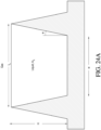
- the microstructured surface can comprise generally inverse-trapezoid-shaped structures, each including a first ridge and a second ridge having similar dimensions that project from the surface and defining a first channel therebetween.
- the height of the first and second ridge can be in the range of about 30 and about 200 ⁇ m.
- the generally inverse-trapezoid-shaped structures can comprise a second channel within the within the first channel and adjacent the first ridge and a third channel within the first channel and adjacent the second ridge, the second and third channels having similar dimensions and being recessed from the first channel.
- the depth of the second and third channel can be in the range of about 5 and about 10 ⁇ m.
- the height of the first channel can be in the range of about 2 and about 5 times taller than the depth of the second and third channels.
- the height of the first channel can be in the range of about 2 and about 3 times taller than the depth of the second and third channels.
- the height of the first channel can be in the range of about 3 and about 5 times taller than the depth of the second and third channels.
- the height of the first channel can be in the range of about 3 and about 5 times taller than the depth of the second and third channels.
- the height of the first channel can be in the range of about 3 and about 5 times taller than the depth of the second and third channels.
- the critical contact angle ⁇ for the generally inverse-trapezoid-shaped structures can satisfy the equation: ⁇ ⁇ arccos ⁇ cos ⁇ + 2 sin ⁇ ⁇ cos ⁇ + 2 where ⁇ is the ratio of the cross-sectional width of the base of the first channel to the cross-sectional height of the ridges, measured from the base of the first channel, and ⁇ is the angle between the vertical axis and a side of the first or second ridge.
- the microchannels can be generally square-shaped.
- the critical contact angle ⁇ for the microchannels can satisfy the equation: ⁇ ⁇ arccos 0.5 0.5 + X where X represents the height-to-width aspect ratio for the square shaped channels.
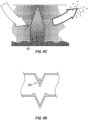
- the microchannels can be generally v-shaped.
- the critical contact angle ⁇ of the microchannels can satisfy the equation: ⁇ ⁇ arccos sin ⁇ 2 where ⁇ represents the angle of the v-shape.
- the microstructured surface can comprise micropillars.
- the micropillars can have substantially the same cross sectional dimensions. At least some of the micropillars can have different cross sectional dimensions from other micropillars.
- the microstructured surface can comprise inverted trapezoids bounded by microridges.
- the foregoing component can be incorporated in a mask.
- the mask can further comprise a drain in communication with the second region.
- the foregoing component can be incorporated in a conduit.
- the component can form at least a portion of an inner wall of the conduit.
- the component can be an insert in an inner lumen of the conduit.
- a wall of the conduit can be configured to communicate with a heat source.
- a component for use in a medical circuit comprises a reservoir portion configured to hold a liquid; an evaporator portion adjacent the reservoir portion configured to facilitate evaporation of the liquid; and a microstructured surface configured to transport liquid from the reservoir portion to the evaporator portion.
- the foregoing component has one, some, or all of the following properties, as well as properties described elsewhere in this disclosure.
- the evaporator portion can be heatable.
- the microstructured surface can comprise microchannels having an aspect ratio that is lower near the reservoir portion and higher near the evaporator portion the aspect ratio increases along a gradient.
- the microstructured surface can comprise first microchannels extending generally horizontally near the reservoir portion and second microchannels extending generally vertically near the evaporator portion, wherein the first microchannels are configured to transport liquid to the second microchannels.
- the foregoing component can be incorporated in a mask.
- the foregoing component is incorporated in a humidification chamber suitable for use with a humidifier.
- the component can form at least a portion of an inner wall of the humidification chamber.
- the humidification chamber can comprise walls configured to be heated by a heater base of the humidifier.
- the humidification chamber can comprise walls configured to be heated by a heating member distinct from the humidifier.
- the humidification chamber can further comprise insulation disposed at least on or over a wall of the humidification chamber near the evaporator portion.
- the humidification chamber can further comprise at least one internal guide wall configured to guide a flow of gases within the humidification chamber.
- the at least one internal guide wall comprises a plurality of guide walls.
- the plurality of guide walls can be arranged concentrically.
- a flow channel can be defined between adjacent ones of the plurality of guide walls.
- the plurality of guide walls can define multiple flow channels, wherein at least some of the flow channels vary in size relative to one another.
- the guide wall or guide walls can be generally U-shaped and extend between an inlet port and an outlet port of the humidification chamber.
- the microstructured surface can form at least a portion of the guide wall or guide walls.
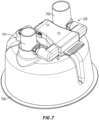
- the humidification chamber comprises a mixing element within the humidification chamber that facilitates mixing of gaseous and liquid phases of the water.
- the mixing element can be movable in response to a flow of gas through the humidification chamber.
- the mixing element can be a turbine comprising a plurality of blades.
- the component can comprise at least one of the plurality of blades.
- the humidification chamber can further comprise a dual valve arrangement that controls the entry of water into the humidification chamber through a water inlet, wherein at least one of the valves is not controlled by a float.
- a first valve can be controlled by a float and a second valve can be controlled by an actuator arrangement comprising a water level sensor and a valve actuator. The second valve can be normally biased to a closed position and can be moved to an open position by the valve actuator.
- the humidification chamber can comprise a planar wall and the water level sensor can be located on the planar wall.
- the inlet port and the outlet port can be located adjacent the planar wall.
- the foregoing component can be incorporated in a conduit.
- the microstructured surface can form at least a portion of an inner wall of the conduit.
- the microstuctured surface can be disposed on an insert in an inner lumen of the conduit.
- a wall of the conduit is configured to communicate with a heat source.
- a medical circuit component for use with humidified gas comprises: a wall defining a space within and wherein at least a part of the wall comprises a surface including a plurality of microchannels in and on a substrate having an outward surface with an equilibrium contact angle less than about ⁇ /2 radians, the microchannels being configured, in use, to wick liquid from a first region holding liquid water to a second region exposed to an air flow to or from a patient, and the microchannels comprising first microchannels having side portions and a bottom portion lower than the outer surface of the substrate and second microchannels having side portions higher than the outer surface of the substrate, wherein the side portions of the second microchannels are formed by ridges around or between the first microchannels.
- the foregoing medical circuit has one, some, or all of the following properties, as well as properties described elsewhere in this disclosure.
- the microstructures can be generally inverse-trapezoid-shaped structures, each including a first ridge and a second ridge having similar dimensions that project from the surface and defining a first channel therebetween.
- the height of the first ridge and the second ridge can be in the range of about 30 and about 40 ⁇ m.
- the generally inverse-trapezoid-shaped structures can comprise a second channel within the within the first channel and adjacent the first ridge and a third channel within the first channel and adjacent the second ridge, the second and third channels having similar dimensions and being recessed from the first channel.
- the depth of the second and third channel can be in the range of about 5 and about 10 ⁇ m.
- the height of the first channel can be in the range of about 2 and about 5 times taller than the depth of the second and third channels.
- the height of the first channel can be in the range of about 2 and about 3 times taller than the depth of the second and third channels.
- the height of the first channel can be in the range of about 3 and about 5 times taller than the depth of the second and third channels.
- the height of the first channel can be in the range of about 3 and about 5 times taller than the depth of the second and third channels.
- the critical contact angle ⁇ for the generally inverse-trapezoid-shaped structures can satisfy the equation: ⁇ ⁇ arccos ⁇ cos ⁇ + 2 sin ⁇ ⁇ cos ⁇ + 2 where ⁇ is the ratio of the cross-sectional width of the base of the first channel to the cross-sectional height of the ridges, measured from the base of the first channel, and ⁇ is the angle between the vertical axis and a side of the first or second ridge.
- the first microchannels can be generally square-shaped.
- the critical contact angle ⁇ for the first microchannels can satisfy the equation: ⁇ ⁇ arccos 0.5 0.5 + X where X represents the height-to-width aspect ratio for the square shaped channels.
- the first microchannels can be generally v-shaped.
- the critical contact angle ⁇ of the first microchannels can satisfy the equation: ⁇ ⁇ arccos sin ⁇ 2 where ⁇ represents the angle of the v-shape.
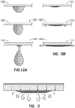
- a component for use in a medical circuit comprises a generally horizontal, planar microstructured surface configured to disperse a liquid placed thereon.
- the microstructured surface can be placed in a path of a flowing gas and a liquid dispenser can be configured to dispense the liquid onto the microstructured surface.
- the microstructured surface comprises surface irregularities.
- the surface irregularities comprise at least one of the group consisting of granules, ridges, grooves, channels, and particles.
- the liquid dispenser comprises at least one dropper configured to dispense the liquid one drop at a time on the microstructured surface.
- the liquid dispenser comprises a substantially flat plate positioned a distance above the microstructured surface, the plate including a plurality of holes through which the liquid is able to fall onto the microstructured surface below.
- a component for use in a medical circuit comprises a generally horizontal, planar microstructured surface configured to disperse a liquid placed thereon, wherein the microstructured surface is placed in a path of a flowing gas; and a liquid dispenser configured to dispense the liquid onto the microstructured surface.
- the foregoing component has one, some, or all of the following properties, as well as properties described elsewhere in this disclosure.
- the microstructured surface can comprise surface irregularities.
- the surface irregularities can comprise at least one of the group consisting of granules, ridges, grooves, channels, and particles.
- the liquid dispenser can comprise at least one dropper configured to dispense the liquid one drop at a time on the microstructured surface.
- the liquid dispenser can comprise a substantially flat plate positioned a distance above the microstructured surface, the plate including a plurality of holes through which the liquid is able to fall onto the microstructured surface below.
- a humidification chamber suitable for use with a humidifier comprises an exterior wall defining an interior space and at least one internal guide wall within the interior space and configured to guide a flow of gases within the humidification chamber.
- the foregoing humidification chamber has one, some, or all of the following properties, as well as properties described elsewhere in this disclosure.
- the at least one internal guide wall can comprise a plurality of guide walls.
- the plurality of guide walls can be arranged concentrically.
- a flow channel can be defined between adjacent ones of the plurality of guide walls.
- the plurality of guide walls can define multiple flow channels, wherein at least some of the flow channels vary in size relative to one another.
- the guide wall or guide walls can be generally U-shaped and extend between an inlet port and an outlet port of the humidification chamber.
- a microstructured surface can form at least a portion of the guide wall or guide walls.
- the guide wall or guide walls can be attached to a top wall of the humidification chamber.
- the humidification chamber can further comprises a mixing element within the humidification chamber that facilitates mixing of gaseous and liquid phases of the water.
- a humidification chamber suitable for use with a humidifier comprises an exterior wall defining an interior space; and a mixing element within the humidification chamber that facilitates mixing of gaseous and liquid phases of the water.
- the foregoing humidification chamber has one, some, or all of the following properties, as well as properties described elsewhere in this disclosure.
- the mixing element can be movable in response to a flow of gas through the humidification chamber.
- the mixing element can be a turbine comprising a plurality of blades.
- the humidification chamber can further comprise a dual valve arrangement that controls the entry of water into the humidification chamber through a water inlet, wherein at least one of the valves is not controlled by a float.
- a first valve can be controlled by a float and a second valve can be controlled by an actuator arrangement comprising a water level sensor and a valve actuator. The second valve can be normally biased to a closed position and can be moved to an open position by the valve actuator.
- the humidification chamber can comprises a planar wall and the water level sensor can be located on the planar wall.
- the inlet port and the outlet port can be located adjacent the planar wall.
- a bottom surface of the turbine can comprise a projection that defines an axis of rotation.
- the turbine can comprise a base and the plurality of blades can be connectable to the base.
- the blades can be generally or substantially planar.
- a humidification chamber suitable for use with a humidifier comprises an exterior wall defining an interior space; a water inlet that permits water to enter the interior space; a primary valve that controls the entry of water into the humidification chamber through the water inlet, wherein the primary valve is controlled by a float; and a secondary valve that controls entry of water into the humidification chamber through the water inlet, wherein the secondary valve is not controlled by a float.
- the foregoing humidification chamber has one, some, or all of the following properties, as well as properties described elsewhere in this disclosure.
- the secondary valve can be controlled by an actuator arrangement comprising a water level sensor and a valve actuator.
- the second valve can be normally biased to a closed position and can be moved to an open position by the valve actuator.
- the second valve can comprise a valve body assembly having unitary spring arms that normally bias the valve body assembly to a closed position of the second valve.
- the humidification chamber can comprise a planar wall and the water level sensor can be located on the planar wall.
- the inlet port and the outlet port can be located adjacent the planar wall.
- microstructures for humidification and/or condensate management include microstructures for humidification and/or condensate management.
- the disclosed microstructures can be incorporated into a variety of components, including tubes (e.g., inspiratory breathing tubes and expiratory breathing tubes and other tubing between various elements of a breathing circuit, such as ventilators, humidifiers, filters, water traps, sample lines, connectors, gas analyzers, and the like), Y-connectors, catheter mounts, humidifiers, and patient interfaces (e.g., masks for covering the nose and face, nasal masks, cannulas, nasal pillows, etc.), floats, probes, and sensors in a variety of medical circuits.
- tubes e.g., inspiratory breathing tubes and expiratory breathing tubes and other tubing between various elements of a breathing circuit, such as ventilators, humidifiers, filters, water traps, sample lines, connectors, gas analyzers, and the like
- Y-connectors e.g.,
- Medical circuit is a broad term and is to be given its ordinary and customary meaning to a person of ordinary skill in the art (that is, it is not to be limited to a special or customized meaning).
- a medical circuit is meant to include open circuits, such as certain CPAP systems, which can comprise a single inspiratory breathing tube between a ventilator/blower and a patient interface, as well as closed circuits.
- FIG. 1 shows a medical circuit according to at least one embodiment. More specifically, FIG. 1 shows an example breathing circuit.
- a breathing circuit can be, for example, a continuous, variable, or bi-level positive airway pressure (PAP) system or other form of respiratory therapy.
- PAP positive airway pressure
- the breathing circuit includes one or more medical tubes, a humidifier, and a patient interface. Any or all of these components, and other components, of the medical circuit can incorporate microstructures for humidification and/or condensate management.
- a microstructure generally may be defined as a structure having microscale dimensions in the range of 1 to 1000 microns ( ⁇ m) (or about 1 to 1000 ⁇ m).
- Gases can be transported in the circuit of FIG. 1 as follows. Dry gases pass from a ventilator/blower 105 to a humidifier 107, which humidifies the dry gases.
- the ventilator/blower 105 can be integrated with the humidifier 107.
- the humidifier 107 connects to an inlet 109 (the end for receiving humidified gases) of an inspiratory tube 103 via an outlet port 111, thereby supplying humidified gases to the inspiratory tube 103.
- An inspiratory tube is a tube that is configured to deliver breathing gases to a patient. The gases flow through the inspiratory tube 103 to an outlet 113 (the end for expelling humidified gases), and then to a patient 101 through a patient interface 115 connected to the outlet 113.
- the outlet 113 is a Y-piece adapter.
- An expiratory tube 117 also connects to the outlet 113.
- An expiratory tube is a tube that is configured to move exhaled humidified gases away from a patient.
- the expiratory tube 117 returns exhaled humidified gases from the patient interface 115 to the ventilator/blower 105.
- the inspiratory tube 103 and/or expiratory tube 117 according to at least one configuration can comprise microstructures. These tubes (and others) are described in greater detail below.
- a fan 121 can improve gas flow into the ventilator/blower 105 by drawing air or other gases through the vent 119.
- the fan 121 can be, for instance, a variable speed fan, where an electronic controller 123 controls the fan speed.
- the function of the electronic controller 123 can be controlled by an electronic master controller 125 in response to inputs from the electronic master controller 125 and/or a user-set value of pressure or fan speed via a dial 127.
- the humidifier 107 comprises a humidification chamber 129 containing a volume of water 130 or other suitable humidifying liquid.
- the humidification chamber 129 is removable from the humidifier 107 after use. Removability allows the humidification chamber 129 to be more readily sterilized or disposed.
- the humidification chamber 129 portion of the humidifier 107 can be a unitary construction.
- the body of the humidification chamber 129 can be formed from a non-conductive glass or plastics material.
- the humidification chamber 129 can also include conductive components.
- the humidification chamber 129 can include a highly heat-conductive base (for example, an aluminum base) contacting or associated with a heater plate 131 on the humidifier 107.
- the humidifier 107 may be a standalone humidifier, such as any of the humidifiers in the respiratory humidification range of Fisher & Paykel Healthcare Limited of Auckland, New Zealand.
- An example humidification chamber 129 is described in U.S. Patent No. 5,445,143 to Sims .
- the humidification chamber 129 according to at least one embodiment comprises microstructures and is described in further detail herein.
- the humidifier 107 can also include electronic controls.
- the humidifier 107 includes the electronic master controller 125.
- the electronic master controller 125 is a microprocessor-based controller executing computer software commands stored in associated memory.
- the electronic master controller 125 determines when (or to what level) to energize the heater plate 131 to heat the water 130 within the humidification chamber 129.
- Patient interface 115 can be incorporated.
- Patient interface is a broad term and is to be given its ordinary and customary meaning to a person of ordinary skill in the art (that is, it is not to be limited to a special or customized meaning) and includes, without limitation, masks (such as tracheal mask, face masks and nasal masks), cannulas, and nasal pillows.
- a temperature probe 135 can connect to the inspiratory tube 103 near the patient interface 115, or to the patient interface 115. The temperature probe 135 monitors the temperature near or at the patient interface 115.
- a heating filament (not shown) associated with the temperature probe can be used to adjust the temperature of the patient interface 115 and/or inspiratory tube 103 to raise the temperature of the inspiratory tube 103 and/or patient interface 115 above the saturation temperature, thereby reducing the opportunity for unwanted condensation.
- the patient interface 115 can comprise microstructures and is described in greater detail below.
- exhaled humidified gases are returned from the patient interface 115 to the ventilator/blower 105 via the expiratory tube 117.
- the expiratory tube 117 can have a temperature probe and/or heating filament, as described above with respect to the inspiratory tube 103, integrated with it to reduce the opportunity for condensation. Furthermore, the expiratory tube 117 need not return exhaled gases to the ventilator/blower 105.
- exhaled humidified gases can be passed directly to ambient surroundings or to other ancillary equipment, such as an air scrubber/filter (not shown). In certain embodiments, the expiratory tube is omitted altogether.
- the inspiratory tube 103, expiratory tube 117, humidification chamber 129, and/or patient interface 115 of the example medical circuit can comprise microstructures.
- a discussion of these components follows. The invention is not limited by these embodiments, however, and it is contemplated that the disclosed microstructures can be integrated into a variety of medical components that contact and/or transport humidified gases, such as humidified air.
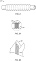
- FIG. 2 shows a perspective view of a tube 201 suitable for use in a medical circuit, according to at least one embodiment.
- the tube 201 can be corrugated, which advantageously improves the tube's flexibility.
- the tube 201 can have a relatively smooth, non-corrugated wall in certain embodiments.
- the tube 201 can be used for transporting gases to and/or from infant or neonatal patients. In certain embodiments, the tube 201 can be used for transporting gases to and/or from standard patients, such as older children and adults.
- standard patients such as older children and adults.
- the tube 201 is formed from an extrudate comprising one or more polymers.
- the polymer is selected so that the resulting tube 201 is generally flexible.
- Preferred polymers include Linear Low Density Polyethylene (LLDPE), Low Density Polyethylene (LDPE), Polypropylene (PP), Polyolefin Plastomer (POP), Ethylene Vinyl Acetate (EVA), Plasticized Polyvinylchloride (PVC), or a blend of two or more of these materials.
- the polymer(s) forms at least 98.4 (or about 98.4), 98.5 (or about 98.5), 98.6 (or about 98.6), 98.7 (or about 98.7), 98.8 (or about 98.8), 98.9 (or about 98.9), 99.0 (or about 99.0), 99.1 (or about 99.1), 99.2 (or about 99.2), 99.3 (or about 99.), 99.4 (or about 99.4), 99.5 (or about 99.5), 99.6 (or about 99.6), 99.7 (or about 99.7), 99.8 (or about 99.8), or 99.9 (or about 99.9) weight percent (wt. %) of the total extrudate.
- the extrudate comprises 99.488 (or about 99.488) wt. % or about 99.49 (or about 99.49) wt. % LLDPE.
- the tube 201 is formed from a foamed polymer as described in commonly assigned International Publication No. WO 2001/077250 A1 , which is incorporated by reference in its entirety.
- microstructures may be formed of soft metal materials, such as aluminum foil, brass, and copper.
- the materials selected can have a high surface energy.
- the substrate materials can be coated and can include an additive that increases the surface energy of the substrate material.
- the use of the metal alone without being formed into microstructures may be advantageous simply because of the high surface energy.
- microstructures may be formed of the metals, for example, by first forming the soft metal into a film or a thin film and subsequently stamping the material to form microstructures. The stamped material may then be used to form any number of suitable components in the humidification devices of the present disclosure.
- At least an interior portion of the tube 201 may formed of a metal that may or may not have been stamped to form microstructures.
- a stamped metallic film may form a surface on any number of structures (walls, towers, fins, base, etc.) within a humidification chamber.
- the tube 201 can comprise one or more conductive filaments.
- the tube 201 can comprise two or four conductive filaments, and pairs of the conductive filaments can be formed into a connecting loop at one or both ends of the tube 201.
- the one or more filaments can be disposed on the outside of the tube 201, for example, spirally wound around the outside of the tube 201, or disposed on the inner wall of the tube 201, for example, spirally wound around along the lumen wall. Filaments are discussed in greater detail below.
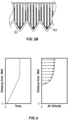
- the inner walls of the tube 201 comprise microstructures 301, as shown in FIG. 3A (not to scale). A first magnified view of a portion of the microstructures 301 is shown in FIG. 3B.
- FIG. 3A A first magnified view of a portion of the microstructures 301 is shown in FIG. 3B.
- FIG. 3B shows the microstructures 301 at a greater magnification than FIG. 3A .
- the microstructures 301 are axially disposed along the tube 201 (that is, the microstructures extend in a direction perpendicular to longitudinal length of the tube 201).
- Polymers generally have a low surface energy, resulting in poor wettability.
- Surfactants such as cationic surfactants, can be particularly desirable additive materials.
- Suitable surface modifying agents include glycerol monostearate (GMS), ethoxylated amine, alkanesulphonate sodium salt, and lauric diethanolamide and additives comprising these substances.
- MLDNA-418 supplied by Clariant (New Zealand) Ltd.
- the surface modifying agent comprises at least about 0.05 (or about 0.05), 0.1 (or about 0.1), 0.15 (or about 0.15), 0.2 (or about 0.2), 0.25 (or about 0.25), 0.3 (or about 0.3), 0.35 (or about 0.35), 0.4 (or about 0.4), 0.45 (or about 0.45), 0.5 (or about 0.5), 1.1 (or about 1.1), 1.2 (or about 1.2), 1.3 (or about 1.3), 1.4 (or about 1.4), or 1.5 (or about 1.5) wt.
- the tube extrudate comprises 0.25 wt. % (or about 0.25 wt. %) of surface modifying agent.
- the tube extrudate comprises 0.5 wt. % (or about 0.5 wt. %) of surface modifying agent.
- Suitable hydrophilizing agents can be any agent or agents generally capable of increasing the hydrophilic character of a composition.
- the surfactant or hydrophilizing agent can comprise an ethoxylized fatty alcohol, such as those described in EP 0 480 238 B1 .
- the surfactant or hydrophilizing agent can comprise a non-ionic surface-active substance, such as the nonylphenolethoxylates, polyethylene glycol-monoesters and diesters, sorbitan esters, polyethylene glycol-monoethers and diethers and others described in EP 0 268 347 B1 , or a non-ionic perfluoralkylated surface-active substance, such as those described in WO 87/03001 .
- the surfactant or hydrophilizing agent can contain silicon moieties.
- the surfactant or hydrophilizing agent can comprise a wetting agent, such as hydrophilic silicon oils as described in the above-mentioned WO 87/03001 and EP 0 231 420 B1 .
- the surfactant or hydrophilizing agent can comprise polyether carbosilanes, such as those described in WO 2007/001869 , particularly at pages 13 and 14. Other such suitable agents are described in US 5,750,589 , US 4,657,959 and EP 0 231 420 B1 , as referenced in WO2007/001869 .
- the surfactant or hydrophilizing agent can comprise ethoxylated surfactants containing a siloxane solubilizing group, such as those described in the above-mentioned US 4,657,949 and WO2007/001869 .
- ethoxylated surfactants are the SILWET ® line of surface active copolymers (e.g., SILWET ® L-77) available from Momentive Performance Materials, Inc. of Albany, New York USA and the MASIL ® SF19 available from Emerald Performance Materials, LLC of Cuyahoga Falls, Ohio USA.
- one or more hydrophilizing agents are applied to a microstructured surface after the microstructures are formed.
- the microstructured surface can be dipped in, sprayed with, or otherwise applied with a suspension of ELVAMIDE ® nylon multipolymer resin (E. I. du Pont de Nemours & Co., Wilmington, DE) in a volatile solvent, such as methanol or ethanol.
- a volatile solvent such as methanol or ethanol.
- the volatile solvent is then allowed to evaporate.
- a thin (in the range of 1 ⁇ m and 10 ⁇ m or in the range of about 1 ⁇ m and about 10 ⁇ m) layer of ELVAMIDE ® resin coats the microstructures, improving the surface hydrophilicity.
- Suitable methods include physical, chemical, and radiation methods.
- Physical methods include, for example, physical adsorption and Langmuir-Blodgett films.
- Chemical methods include oxidation by strong acids, ozone treatment, chemisorption, and flame treatment.
- Radiation methods include plasma (glow discharge), corona discharge, photo-activation (UV), laser, ion beam, electron beam, and gamma irradiation.
- a suitable surface modification method or agent it is possible to provide a tube wall having surface property contact angles of less than 50 (or about 50), 45 (or about 45), 40 (or about 40), 35 (or about 35), 30 (or about 30), 25 (or about 25), 20 (or about 20) degrees (°), as measurable by an angle measurement device such as a goniometer.
- tube walls having surface property contact angles of less than 35° (or about 35°) provide useful results.
- the contact angle is less than ⁇ /2 (or about ⁇ /2). More desirably, the contact angle is 0° or about 0°.
- the sample with 5% MLDNA-418 surface modifying agent produced the lowest measured contact angle compared to other surface modification methods tested.
- the additive material is added to the bulk polymer extrudate. It can be desirable to add the material in the polymer matrix so that the additive material replenishes the surface for the useful life of the tube.
- the material can be added as a surface treatment on the polymer, for example, by coating a surface of the polymer with the material.
- a microstructured surface can be brushed, sprayed, or otherwise coated with additive material such as HYDRON anti-fog coating (MXI, Industries, Lancaster, Pennsylvania), EXXENE anti-fog coatings such as HCAF-100 (Exxene Corporation, Corpus Christi, Texas), and MAKROLON anti-fog (Bayer Corporation) to produce a thin (e.g., 1 ⁇ m or thereabout) coating of additive material.
- a surface coating can be desirable because of low costs and ease of manufacture.
- a thin film of hydrophilic material such as breathable polyurethanes, for example, ESTANE 58245 (Lubrizol Corporation, Wickliffe, Ohio), breathable polyesters, for example, ARNITEL VT3108 (DSM Engineering Plastics, Sittard, Netherlands), or breathable polyamides, for example PEBAX (Arkema, Colombes, France) can be cast as a surface modifying agent.
- breathable polyurethanes for example, ESTANE 58245 (Lubrizol Corporation, Wickliffe, Ohio), breathable polyesters, for example, ARNITEL VT3108 (DSM Engineering Plastics, Sittard, Netherlands), or breathable polyamides, for example PEBAX (Arkema, Colombes, France)
- PEBAX Arkema, Colombes, France
- ESTANE 58245 pellets can be dissolved in a tetrahydrofuran (THF) of dimethylformamide (DMF) solvent and cast onto microstructures machined from brass or aluminum using a micromilling process.
- Typical dimensions for the thin film are in the range of 1 to 10 ⁇ m (or about 1 to 10 ⁇ m).
- the solvent, breathable material, and microstructure material combination is selected such that the microstructure shape and quality is not substantially influenced, for example, by dissolving the microstructures with the solvent.
- a tube e.g., the inspiratory tube 103 or expiratory tube 117
- a tube generally extends in a horizontal direction, although certain portions can extend vertically, particularly near the ends of the tube, and some portions can be sloped.
- condensate tends to run down the vertical and sloped portions of the tube and pool at the lowest points of the generally horizontal tube.
- microstructures When microstructures are perpendicular to the generally horizontal tube bottom, the microstructures will move pooled condensate vertically, against gravity.
- This action increases the amount of condensate on the tube walls and, thus, the surface area of condensate exposed to the air stream. Exposing a greater surface area of condensate to the air stream increases the likelihood that the condensate will evaporate into the air stream. Therefore, the perpendicular configuration reduces the condensate pooled in the tube and improves the likelihood that the air flowing through the tube maintains a desired level of humidity near saturation.
- This configuration can be advantageous because it causes minimal disruption to the airflow within the tube lumen, as there are no structures extending into the lumen.
- At least one embodiment includes the realization that microstructures do not have to extend into or cover the lumen in order to enhance evaporation.
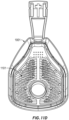
- FIG. 19A illustrates an embodiment of the humidification chamber 129 to which is attached at an inlet port 701 a tube 1901 incorporating microstructures 1903.
- the other end of the tube 1901 is connected to a corrugated dry line 1909 leading from a ventilator/blower (not shown). Air flows from the ventilator/blower, into the dry line 1909, through the tube 1901, into the inlet port 901, and then into the humidification chamber 129.
- Tube 1901 has a non-corrugated wall.
- a liquid, such as water, can be dispensed into the tube 1901 some distance above the inlet port 701 so that the water runs through and along the microstructures 1903 in the direction of the humidification chamber 129.
- FIG. 19A illustrates an embodiment of the humidification chamber 129 to which is attached at an inlet port 701 a tube 1901 incorporating microstructures 1903.
- the other end of the tube 1901 is connected to a corrugated dry line 1909 leading from a ventilator/blower (not shown). Air flows from the
- the microstructures 1903 may be oriented longitudinally in the direction of the tube.
- the microstructures 1903 may alternatively be oriented in a circumferential direction along the tube wall.
- the tube 901 of FIG. 19A can advantageously be used to pre-humidify gas flowing into the humidification chamber 129.
- the liquid can be metered onto the inner surface of the tube 1901 such that a controlled introduction spreads the liquid around the circumference and, through the use of the microstructures and gravity, along the inner surface of the tube 1901.
- the introduction of liquid can be controlled using any suitable rate limiting device, such as a flow restrictor.
- the rate of water flowing into the tube 1901 may be regulated using the rate limiting device to maximize the interplay between the water and the microstructures 1903 in the tube 1901. For example, increasing the amount of water in the tube 1901 may increase the amount of evaporation that occurs.
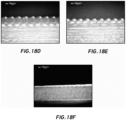
- the microstructures 1903 may be most effective if not completely covered or coated in water. It has been found that evaporation occurs on a rough surface primarily along the edges of the water and the surrounding structure. Accordingly, it may be desirable to control the amount of water flowing through the tube 1901 so as to maximize the number of edges against the water.
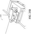
- FIG. 19B shows an example means for delivering liquid to the tube 1901 in the region of box 1910 of FIG. 19A .
- a liquid supply tube (not shown) provides liquid to a collar 1911 via input 1913, and the collar 1911 supplies liquid to the tube 1901.
- An optional rate limiting device (not shown), as described above, can be used to regulate the flow of liquid to the collar 1911.
- the liquid supply tube can extend between the rate limiting device and the collar 1911.
- the collar 1911 optionally can include microchannels on an outer surface of a sleeve 1915, which microchannels can be in fluidic communication with the microchannels on the tube 1901.
- the collar 1911 can include a port to which the dry line 1909 can connect. Air flowing down or through the tube 1901 toward the humidification chamber 129 begins to evaporate and carry away the water from the inner surface of the tube 1901. Thus, the air reaching the humidification chamber 129 has already acquired at least some water vapor.
- a heater wire 1907 can be incorporated onto or into the tube 1901.
- the heater wire 1907 of FIG. 19A is shown in schematic representation on the outside (or outer surface) of the tube 1901.
- the heater wire 1907 can be disposed within the tube 1901 (e.g., within the tube lumen or on the lumen wall) and/or embedded in the tube 1901 wall.
- a heat jacket (not shown) may also be incorporated into, or may surround, at least a portion of the tube 1901. The heat jacket can further enhance the evaporation of the water or liquid into the flowing gas.
- the tube 1901 can have heaters printed onto one or more portion of the tube 1901.
- the tube 1901 can include structures such as thick film heating elements, etched foil or wire elements to provide a heating element.
- the tube 1901 with the microstructures 1903 may be formed in any suitable manner and using any suitable materials.
- the tube 1901 can be formed of a corrugated sheet formed from a hydrophilic polymer. Once formed, the corrugated material can be wrapped to form the tube 1901 with the microstructures 1903 running at least a portion of the length of the inner surface of the resulting structure.
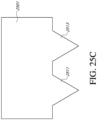
- the microstructures 1903 are V-shaped trenches. In some embodiments, the V-shaped trenches comprise troughs that are about 30 ⁇ m apart from neighboring troughs when the sheet is laid out flat. In some configurations, the sheet, and therefore the resulting tube 1901, may be about 150 mm long and, once folded to form the tube 1901, may have a diameter of about 20 mm.
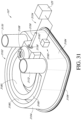
- FIG. 37A illustrates an alternative configuration of the system of FIG. 1 that eliminates the humidifier 107 of FIG. 1 .
- Dry gases pass from a ventilator/blower 105 to a humidifier tube 3701, which humidifies the dry gases.
- the humidifier tube 3701 connects to an inspiratory tube 103, which delivers the humidified gas to the patient 101 via an outlet 113 (in this example, a Y-piece adapter).
- An expiratory tube 117 also connects to the outlet 113.
- the expiratory tube 117 returns exhaled humidified gases from the patient interface 115 to the ventilator/blower 105.
- the inspiratory tube 103 and/or expiratory tube 117 according to at least one configuration can comprise microstructures, as described in this disclosure.
- the humidifier tube 3701 comprises a microstructured conduit 3705.
- the inner wall (adjacent the lumen) of the microstructured conduit comprises microstructures as described herein.
- the microstructures can be disposed circumferentially.
- the microstructures alternatively can be disposed longitudinally.
- the microstructured conduit 3705 is desirably non-corrugated. Nevertheless, the microstructured conduit 3705 can be corrugated in certain embodiments.
- a liquid supply conduit 3703 can be disposed adjacent the microstructured conduit 3705.
- the liquid supply conduit 3703 provides the humidifying liquid to the humidifier tube 3701.
- the liquid flowing through the liquid supply conduit 3703 can be delivered as a flow-through system.
- the liquid can be delivered via a recirculator.
- the introduction of liquid is controlled using a suitable rate limiting device, such as a flow restrictor.
- the lumen of liquid supply conduit 3703 is in fluidic communication with the lumen of microstructured conduit 3705.
- the lumens can communicate via a plurality of small or capillary-size holes, via a small or capillary-size channel, via a semi-permeable membrane, or via a liquid-permeable material such as nylon.
- the diameter of liquid conduit 1905, the size of the holes or channel, the permeability of the membrane, and/or the density of the material can be selected to further control the rate of at which liquid is provided onto the inner surface of the tube 1901.
- FIG. 37C a front-plan view of the microstructured conduit 3705 and liquid supply conduit 3703 of FIG. 37A and 37B , when in use, a liquid in the liquid supply conduit 3703 passes into the microstructured conduit 3705. The liquid is wicked up and spreads over the surface of the microstructured conduit 3705, and the air flowing through the microstructured conduit 3705 takes up the liquid, thereby humidifying the air.
- a collar can be disposed on a forward end of the microstructured conduit 3705 (that is, on the end nearer the ventilator/blower 105).
- the collar can be essentially similar to the collar 1911 described in the context of FIG. 19B .
- FIG. 4 illustrates a cross section of an example microstructure 301a.
- the microstructure 301a is a continuous microchannel with a wedge-like structure.
- a continuous microchannel generally may be defined as a continuous channel having dimensions of 1000 ⁇ m (or about 1000 ⁇ m) or smaller.
- the microchannel has a depth d of 20-40 ⁇ m (or about 20-40 ⁇ m), a maximum width w of 20 ⁇ m (or about 20 ⁇ m), and an angle ⁇ of 30-60° (or about 30-60°).
- a tube surface has a microchannel-to-solid ratio of 1:1 (or about 1:1).
- the foregoing dimensions are not limiting, and additional suitable dimensions are discussed in greater detail below. Because of the scale differences between these example embodiments and the example tube dimensions discussed above, microstructured surfaces can reside and operate in an open system, rather than a closed system, such as a lab-on-a-chip.
- the microstructures includes a base substrate having an equilibrium contact angle less than ⁇ /2 (or about ⁇ /2).
- FIG. 16 is a graph of example conditions for wicking in continuous microchannels, specifically square (1601) and v-shaped (1603) grooves. In the area below the curves, wicking into the channels tends to occur. In the area slightly above the curves, droplet stretching into a number of meta-stable equilibria is observed, but wicking tends not occur. In the area well above the curves, droplet stretching is not observed and wicking does not occur.
- microstructures can promote the dispersion of liquid droplets and, therefore, can reduce the thickness/depth of the droplets, which increases the liquid/vapor surface area when the equilibrium contact angle is less than about 90°.
- the surface roughness of microchannels also can play a role in wicking. It is believed that microstructured or nanostructured bumps within the microchannels could act to pin the solid/liquid/vapor contact line, increase surface area, and/or act as nucleating sites for condensation.
- FIG. 17 shows microchannels similar to those shown in FIG. 18C , but viewed using an environmental scanning electron microscope. Roughness can clearly be seen on the surface.
- surface roughness can have a detrimental effect on spreading and evaporation if the contact angle is greater than about 90° because the liquid droplets will spread less, which will reduce the liquid/vapor surface area. For at least this reason, constructions having an equilibrium contact angle of less than about 90° are generally preferred.
- the continuous microchannel profile can be sinusoidal or a sharp trench.
- the microchannel has an aspect ratio that increases with distance, for example, a chemical or physical gradient.
- a channel depth gradient is used to control movement of a liquid in a particular direction. It has been found that liquids tend to move in the direction of the deeper channels. A gradient can be desirable because, provided that hysteresis is slow, the substrate can force a droplet to move toward an area of higher energy in order to lower it. Gradients can also speed up or otherwise improve the wicking of liquid.
- a channel depth gradient is used to move liquid toward a region of higher air flow thereby increasing evaporation.
- larger channels are used along vertical walls of a structure to direct water from the bottom of the structure to the top of the corrugated structure thereby bringing the water closer to a heating element for evaporation.
- a surface can comprise discrete features such as cylindrical, pyramidal, or cube-shaped posts or pillars.
- Microstructures can also comprise a hierarchy of the foregoing features.
- discrete features are uniform or partially uniform.
- the discrete features are randomly distributed on a surface.
- some embodiments utilize crystals having irregular shapes spread across or adhered to a surface.
- an irregular surface i.e., not smooth
- FIGS. 20 and 21 illustrate embodiments that utilize irregular or rough surfaces to enhance evaporation of a liquid.
- FIG. 20 illustrates that a liquid may be applied to a rough surface 2001 using a liquid dispenser 2003 located some distance D from the rough surface 2001 that outputs small amounts of the liquid.
- the drops are emitted as one drop at a time.
- the drops can splash upon contact, which results in smaller droplets.
- Each drop may contact the rough surface 2001 and quickly spread across the rough surface 2001 thereby enhancing the evaporation of the liquid into a gas that flows over the rough surface 2001.
- the rough surface 2001 is heated to further enhance the evaporation of the liquid into the passing gas.
- FIG. 20 has been shown with only a single liquid dispenser 2003, or dropper, some embodiments may comprise more than one liquid dispenser 2003.
- multiple liquid dispensers 2101 can be located at various locations over the rough surface 2001 to increase the coverage of the liquid on the rough surface 2001.
- a surface comprising a plurality of holes serves as the liquid dispenser 2101.
- a liquid, such as water, is allowed to flow over the surface.
- FIG. 21 further illustrates that in some embodiments, the flow of a gas, such as air that is to be humidified, can be channeled or shaped to form a relatively flat stream over the rough surface 2001. Such a configuration may force more of the gas to interact with the rough surface 2001.
- a gas such as air that is to be humidified
- FIG. 22 illustrates one type of rough surface that includes a plurality of ridges 2201 having varying heights and widths. It is believed that rough surfaces having higher height to width ratios (e.g., steeper slopes) spread liquids and increase evaporation. In some configurations, having steeper slopes is believed to increase the number of contact lines. In some embodiments, increasing the number of contact lines between the liquid and the rough surface is believed to increase evaporation. In some embodiments, the presence of taller ridges 2201 may increase the number of contact lines between the liquid and the rough surface thereby increasing evaporation relative to a surface having shorter ridges 2203. In some embodiments, the use of heat applied to rough surface may increase the rate of evaporation particularly at the contact lines.
- height to width ratios e.g., steeper slopes
- having steeper slopes is believed to increase the number of contact lines.
- increasing the number of contact lines between the liquid and the rough surface is believed to increase evaporation.
- the use of a surface having integral microstructures, namely microstructures integrally connected to the underlying surface may allow for better heat transfer if the underlying surface is heated. Such a configuration may improve the ability of heat to assist in the evaporation of the liquid.
- a microstructured surface having a regular pattern may achieve similar results. Similar to droplets on a rough surface, droplets on a surface with microstructures will disperse and evaporate into a passing gas more quickly than a smooth surface having no microstructures or surface irregularities.
- the microstructures are uniform. In some embodiments, the microstructures are sized and arranged according to a pattern if not every microstructure is the same.
- A is a function of surface tension, viscosity, the cross sectional area of the channel, and the contact angle.
- Certain embodiments include the realization that low contact angles, high aspect ratios, high surface tension, and low viscosity can lead to improved wicking. Because wicking length is proportional to the square root of time, the velocity of wicking is inversely proportional to length and inversely proportional to the square root of time. Stated another way, wicking slows down with distance and with the passage of time.
- FIGS. 18A through 18L show images of continuous and discrete microstructures.
- the substrate material in FIG. 18A is polyethylene terephthalate (PET).
- PET polyethylene terephthalate
- the substrate material in the other figures is an acrylic.
- FIG. 18A The v-shaped grooves in FIG. 18A were cut using a double-edge razor blade.
- the other microstructures were fabricated using a 3D printer (ProJet HD 3000).
- microstructures or surfaces incorporating microstructures can be manufactured by direct injection molding or hot embossing.
- CNC computer numerical control
- FIGS. 18B and 18C show square-shaped grooves.
- FIG. 18D shows a front view of a square microchannel array having a gradient in topography, and specifically shows the front view of the long end of the microchannels.
- FIG. 18E shows a front view of the short end of the microchannels of FIG. 18D.
- FIG. 18F shows a side view of a square microchannel array of FIG. 18D .
- the dynamics of wicking can potentially be modified by having microstructures that change in depth with distance.
- This topography can desirably influence the way that liquid evaporates and condenses on the surface.
- Such variable depth configurations can be achieved by embossing, machining, or casting.
- FIG. 18G shows a droplet on square grooves that have not been treated with a surfactant.
- FIG. 18H shows spreading of a droplet on square grooves that have been treated with a surfactant.
- FIGS. 18I and 18J show top-down views of a pillared surface at different magnifications.
- FIG. 18K shows a side view of the pillared surface.
- FIG. 18L shows another embodiment of a microstructure defining a surface shape that is an inverse of the shape of the microstructure of FIG. 18A .
- the microstructure of FIG. 18L comprises alternating taller ridges and shorter ridges, each of which are separated from one another by a small channel or first microchannel.
- the taller ridges are substantially taller than the shorter ridges and may be 2-3 times as tall, or taller, than the shorter ridges.
- the shorter ridges are substantially wider than the taller ridges, such as about 3-5 times wider, for example.
- the cross-sectional height of a small channel is in the range of 5 and 10 ⁇ m (or in the range of about 5 and about 10 ⁇ m), and the cross-sectional height of a ridge is in the range of 30 and 200 ⁇ m (or in the range of about 30 and 200 ⁇ m), such as 40 ⁇ m (or thereabout).
- the small channels can be any suitable size, such as about the width of the taller ridges, for example.
- the cross sectional area of a small channel is approximately equal to one-half the cross sectional area of the adjacent taller ridge.
- the taller ridges define large channels (also referred to as second microchannels or main channels) therebetween, which can communicate with or be contiguous with the small channels.
- a depth of the large channels can be larger than a depth of the small channels, such as up to 2-3 times as large, or larger.
- the small channels can be generally triangular, square, or trapezoidal in cross-sectional shape, while the large channels can have a cross-sectional shape generally similar to an inverted trapezoid.
- the shorter ridges preferably define a significantly larger area than the taller ridges, the upper surfaces of the shorter ridges can be viewed as the outer surface of the material or substrate, with the small channels being recessed from the outer surface and the taller ridges projecting from the outer surface.
- FIG. 18L can be modeled as shown in FIG. 24A .
- a criterion for wicking can be defined that depends on the aspect ratio, channel geometry, and a critical contact angle.
- ⁇ crit arccos ⁇ cos ⁇ + 2 sin ⁇ ⁇ cos ⁇ + 2
- ⁇ is the angle shown in FIG. 24A .
- Wetting will occur when the material's equilibrium contact angle is below the critical angle ⁇ crit
- no wetting will occur when the material's equilibrium contact angle is above the critical angle ⁇ crit .
- the foregoing model is modified by multiplying L ⁇ by sin ⁇ , where ⁇ is the inclination angle from the horizontal axis with respect to the flow direction.
- the small channels have an aspect ratio that is smaller than that needed to satisfy the critical contact angle formula for the respective geometry of the small channel (viz., triangular, square, or trapezoidal) and the wetting criteria for the main channel is met, the small channels promote wetting in the composite channel (which includes the space between the microridges and encompasses both the small channels and the main channel) by increasing the surface area of the structure. It was further observed that liquid will flow in the small channels and the main channel at the same rate.
- liquid in the small channels is typically a very thin film (in the range of 6 and 10 ⁇ m or in the range of about 6 and about 10 ⁇ m), which evaporates faster than the liquid in the main channel.
- small channels having a large aspect ratio can improve evaporation.
- the microstructures 301 can extend along the entire length of the tube 201 or along a portion of the length of the tube 201, such as a central portion that is likely to collect condensate. Alternatively, the microstructures 301 can extend along the tube 201 at regular or irregular intervals, separated by portions with no microstructures.
- the foregoing figures show the microstructures 301 encircling the inner circumference of the tube 201.
- the microstructures 301 need not encircle the entire inner circumference in all embodiments, however.
- the microstructures 301 can be disposed around half or quarter of the circumference.
- the one or more filaments discussed above comprise heating filaments.
- Heating filaments can be embedded or encapsulated in the wall of the tube 201.
- the one or more filaments can be spirally wound in the wall of the tube 201 around the tube lumen.
- the one or more filaments can be disposed within the tube 201, for example, in a spirally-wound configuration as described in U.S. Patent No. 6,078,730 to Huddard et al. .
- the arrangement of heating filaments is not limited to one of the foregoing configurations.
- heating filaments can be arranged in a combination of the foregoing configurations.
- the tube 201 comprises an inner component comprising microstructures.
- An example inner component 501 is shown in FIG. 5A .
- the inner component 501 includes microstructures 301, as described above.
- a magnified view of the inner component 501 is shown in FIG. 5B .
- the example inner component 501 is a serrated strip.
- the inner component 501 is placed and configured within the tube (not shown) such that the bottom portion of the inner component 501 is exposed to liquid condensate 503 within the tube.
- the serrations in the inner component 501 can be sized and configured to complement the corrugations of the tube, such that the tube generally holds the inner component 501 in place.
- FIG. 5A An example inner component 501 is shown in FIG. 5A .
- the inner component 501 includes microstructures 301, as described above.
- a magnified view of the inner component 501 is shown in FIG. 5B .
- the example inner component 501 is a serrated strip.
- the inner component 501 is placed
- the microstructures 301 extend vertically to cover both axial surfaces of the inner component 501 along the longitudinal length of the inner component 501.
- the microstructures 301 can cover one axial surface.
- the microstructures 301 can extend along a portion of the longitudinal length or along regular or irregular intervals of the longitudinal length.
- the inner component 501 can comprise more than one serrated strips.
- an inner component can comprise two serrated strips and resembles a plus-sign having serrations along the longitudinal length. These embodiments are not limiting. A larger number of strips can be incorporated. However, it can be advantageous to have a lower number of strips to improve the airflow through the tube lumen and/or improve tube flexibility.
- Inclusion of the inner component 501 can be advantageous because the inner component 501 can allow the microstructures 301 to extend into the tube lumen and reach the center of the tube 201 lumen.
- airflow velocity increases from the tube wall to the center of the tube lumen (centerline) and reaches a maximum at the centerline.
- water rising up the microstructures 301 in FIGS. 5A and 5B is exposed to the warm, higher velocity air flow. Exposing the condensate to the higher air velocity near the center of the tube increases the likelihood that the condensate will evaporate into the air stream.
- the inner component 501 can be wound inside the tube 201. This configuration can be desirable because it allows the microstructures to extend a distance into the tube 201 lumen, which is exposed to higher airflow velocity than the tube 201 walls.
- the inner component 501 is wound so that at least a portion of the inner component 501 crosses the center of the tube lumen.
- the inner components 501 of any of the foregoing embodiments can incorporate a heating filament, which can improve heating of the airflow along the tube and, thus, the likelihood that condensate in the microchannels will evaporate into the airflow. Incorporating one or more heating filaments into the inner component 501 also decreases the likelihood that condensation will occur on the warm inner component. It was discovered that evaporation is highest at the contact region, where the solid surface, liquid droplet, and evaporated vapor meet. This is due to the proximity to the heated surface. The closer to the solid, the higher the mass transfer.
- certain embodiments include the realization that it can be desirable to have a larger number of narrower channels. For example, higher evaporation rates can be achieved on a surface having ten 100 ⁇ m channels than on a surface having five 200 ⁇ m channels.
- microstructures can be advantageous because it may be used to convey liquids without the use of a pump or pumps. Furthermore, certain embodiments include the realization that microstructured surfaces would not require pumps to direct liquids, as the liquid movement is driven by capillary action.
- a tube may be made from one or more extruded polymer components.
- the properties of the extrudate are described above.
- a first manufacturing method is described with reference to FIG. 14 .
- the method comprises extruding an elongate conduit having a longitudinal axis, a lumen extending along the longitudinal axis, and a wall surrounding the lumen.
- Microstructures can be pressed or otherwise formed on the conduit during extrusion.
- Microstructures can also be molded, printed, cut, thermoformed, or otherwise formed on the conduit after extrusion.
- FIGS. 4 , 8D , and 9D it was observed that cutting microchannels into a surface using a sharp object could result in raised edges around the top portion of the microchannel. Accordingly, in some methods, it can be desirable to grind or polish the surface after microchannel formation to improve surface uniformity.
- the method can also involve corrugating the elongate conduit, such as with a corrugating die. More specifically, the process involves mixing or providing of a master batch of extrudate material (i.e. , material for extrusion), feeding the master batch to an extrusion die head, extruding the extrudate as described above, and (optionally) feeding the elongate conduit into a corrugator using an endless chain of mold blocks to form a corrugated tube.
- a master batch of extrudate material i.e. , material for extrusion
- FIG. 14 generally illustrates a setup where there is provided a feed hopper 1401 for receiving raw ingredients or material (e.g., master batch and other materials) to be passed through a screw feeder 1403 driven by a motor 1405 in direction A toward a die head 1407.
- a molten tube 1409 is extruded out of the die head 1407.
- Conductive filaments can optinally be co-extruded on or in the molten tube 1409.
- An extruder such as a Welex extruder equipped with a 30-40 mm diameter screw and, typically, a 12-16 mm annular die head with gap of 0.5-1.0mm has been found to be suitable for producing low cost tubes quickly.
- Similar extrusion machines are provided by American Kuhne (Germany), AXON AB Plastics Machinery (Sweden), AMUT (Italy), and Battenfeld (Germany and China).
- a corrugator such as those manufactured and supplied by Unicor ® (Hassfurt, Germany) has been found to be suitable for the corrugation step. Similar machines are provided by OLMAS (Carate Brianza, Italy), Qingdao HUASU Machinery Fabricate Co., Ltd (Qingdao Jiaozhou City, P.R. China), or Top Industry (Chengdu) Co., Ltd. (Chengdu, P.R.of China).
- the molten tube 1409 is passed between a series of rotating molds/blocks on the corrugator after exiting the die head 1407 and is formed into a corrugated tube.
- the molten tube is formed by vacuum applied to the outside of the tube via slots and channels through the blocks and/or pressure applied internally to the tube via an air channel through the center of the extruder die core pin. If internal pressure is applied, a specially shaped long internal rod extending from the die core pin and fitting closely with the inside of the corrugations may be required to prevent air pressure escaping endways along the tube.
- the tube may also include include include a plain cuff region for connection to an end connector fitting.
- a molded-plastic end connector fitting can be permanently fixed and/or air tight by friction fit, adhesive bonding, over molding, or by thermal or ultrasonic welding.
- FIG. 15 Another suitable method for manufacturing a tube according to the embodiments described here involves spiral forming, as shown in FIG. 15 .
- the method comprises extruding a tape and spirally winding the extruded tape around a mandrel, thereby forming an elongate conduit having a longitudinal axis, a lumen extending along the longitudinal axis, and a wall surrounding the lumen.
- the method can also include optionally corrugating the elongate conduit.
- Microstructures can be pressed or otherwise formed on the tape during extrusion.
- Microstructures can also be molded, printed, cut, thermoformed or otherwise formed on the tape after extrusion.
- microstructures can also be molded, printed, cut, thermoformed or otherwise formed on the assembled conduit. In some methods, it can be desirable to grind or polish a surface after microchannel formation to improve surface uniformity.
- the extrusion process involves mixing or providing of a master batch of extrudate material (i.e. material for extrusion), feeding the master batch to an extrusion die head, extruding the extrudate into a tape.
- a master batch of extrudate material i.e. material for extrusion
- a reinforcing bead overlays turns of tape.
- the bead may provide a helical reinforcement against crushing for the tube and may also provide a source of heat, chemical or mechanical adhesive for fusing or joining the lapped portions of tape.
- FIG. 15 Shown in FIG. 15 is a molten extruded tube 1501 exiting the die 1503 of an extruder before passing into a corrugator 1505. On exiting the corrugator 1505, a heater wire 1507 is wound about the exterior of the formed tubular component.
- One advantage of the preferred type of the tube manufacture described above with reference to FIG. 15 is that some of the mold blocks B can include end cuff features that are formed at the same time as the tubular component. Manufacture speeds can be significantly increased by the reduction in complexity and elimination of secondary manufacturing processes. While this method is an improvement over separate cuff forming processes, a disadvantage of the prior art plain cuff is that the corrugator must slow down to allow the wall thickness of the tube in this area to increase (the extruder continues at the same speed). The cuff thickness is increased to achieve added hoop strength and sealing properties with the cuff adaptor fitting. Further, the heat of the molten polymer in this thicker region is difficult to remove during the limited contact time with the corrugator blocks and this can become an important limiting factor on the maximum running speed of the tube production line.
- Microstructures having a size in the range of 5 ⁇ m and 30 ⁇ m (or in the range of about 5 ⁇ m and about 30 ⁇ m) can be formed on planar surfaces, including humidification chamber walls and the like.
- a planar surface broadly refers to a non-tubular surface.
- the term "planar surfaces” encompasses curved surfaces, such as the walls of a humidification chamber and turbine-type impeller blades.
- the term “planar surfaces” also encompasses substantially flat surfaces such as paddle-type impeller blades.
- At least one method for forming microstructures comprises providing a device comprising a fine cutting blade.
- FIG. 25A shows a suitable device 2500.
- the device 2500 of FIG. 25A comprises a fine cutting blade 2501, such as a razor blade, and an adjustable weight 2503 at one end.
- the device 2500 is shown cutting a template for a humidification chamber 2505.
- FIG. 25B shows a detail of an example of the cutting blade 2501 suitable for use in the device 2500 of FIG. 25A .
- FIG. 25C shows a cross section of another example of the cutting blade 2501 suitable for use in the device 2500 of FIG. 25A .
- the cutting blade 2501 of FIG. 25C is discussed in greater detail below.
- the device can be attached to a CNC machine capable of drawing the device over a planar surface.
- the force applied by the cutting blade can be in the range of 1 N and 2 N (or in the range of about 1 N and about 2 N).
- Suitable materials for the planar surface include plastics such as acrylic and polypropylene and metals such as aluminum.
- the device cuts the surface at a selected spacing and produces V-shaped grooves, channels, or trenches.
- the weight can be adjusted to alter the depth of the grooves or trenches.
- a hierarchy of grooves, channels, or trenches e.g., groove-in-groove, channel-in-channel, or trench-in-trench
- a smoothing means includes heating the cutting blade 2501 during cutting.
- a smoothing means can also include heating the surface material after cutting.
- Yet another smoothing means includes exposing the surface material to a solvent suitable for dissolving imperfections in the sidewall, such as a chlorinated solvent.
- the device is also suitable for use in a method for forming microstructures similar to those shown in FIG. 18L on a planar surface.
- the method comprises drawing the blade of the device over a template material 2601, such as a metal or plastic as discussed above, to form a grooved surface on the template material 2601.
- a template material 2601 such as a metal or plastic as discussed above
- the method further comprises applying a first impression material 2603 over the grooved surface of the template material 2601.
- Elastomeric impression materials e.g., polyethers, polyvinyl siloxanes (PVSs), polyether-PVS hybrids, alginates, silicone, and silicone rubbers
- PVSs polyvinyl siloxanes
- silicone rubbers are particularly suitable for this purpose.
- the first impression material 2603 can be allowed to cure for a period of time, such as 5 minutes (or about 5 minutes).
- a period of time such as 5 minutes (or about 5 minutes).
- the template material 2601 is removed, leaving the first impression material 2603 with a pattern inverted from that of the template material 2601.
- a second impression material 2605 is applied to the first impression material 2603.
- elastomeric impression materials such as those identified above, are suitable for the second impression material.
- the second impression material 2605 can be allowed to cure for a period of time, such as 5 minutes (or about 5 minutes).
- the first impression material 2603 is removed, leaving the second impression material 2605 with a pattern inverted from that of the first impression material 2603. In other words, the original pattern in the template material 2601 ( FIG. 26A ) is replicated in the second impression material 2605 ( FIG. 26E ).
- a curable material 2609 is applied between the second impression material 2605 and a target surface 2607.
- the target surface 2607 include plastics, such as acrylonitrile butadiene styrene or polycarbonate or metals such as aluminum.
- the curable material 2609 can be applied to a plastic humidification chamber target surface 2607, and the second impression material 2605 can be overlaid on the curable material 2609.
- the surface of the target surface 2607 can be roughened, e.g., by sanding, prior to application of the second impression material 2605 to improve adhesion.
- Suitable materials for the curable material 2609 include UV curable acrylic and heat curable epoxy or heat curable acrylic.
- the second impression material 2605 and the target surface 2607 should preferably be permeable to UV (e.g., transparent to light).
- the target surface 2607 is a transparent plastic, for example.
- UV light 2611 passes through the target surface 2607 and cures the curable material 2609 to form a hardened overlayer on the target surface 2607.
- the target surface 2607-curable material 2609-second impression material 2605 complex can be heated, thereby curing the heat curable material 2609.
- the second impression material 2605 is removed to reveal the target surface 2607 with the hardened overlayer 2613 having a microstructured surface.
- FIGS. 27A-27F show the materials involved in a method similar to that described above with respect to FIGS. 26A-26H .
- the materials of FIGS. 27A-27F are suitable for forming microstructures similar to those in FIG. 18A on a planar surface.
- the method comprises drawing the blade of the device over a template material 2701, such as a metal or plastic as discussed above, to form a grooved surface on the template material 2701.
- the method further comprises applying an impression material 2703 (such as an elastomeric impression material as discussed above) over the grooved surface of the template material 2701.
- FIG. 27C the template material 2701 is removed, leaving the impression material 2703 with a pattern inverted from that of the template material 2701.
- a curable material 2709 (such as a UV-curable or heat curable material as discussed above) is applied between the impression material 2703 and a target surface 2707, such as a metal or plastic planar surface.
- the surface of the target surface 2707 can be roughened, e.g., by sanding, prior to application of the impression material 2703 to improve adhesion.
- UV light 2711 passes through the impression material 2703 and cures the curable material 2709 to form a hardened overlayer on the target surface 2707.
- the UV light 2711 can pass through the target surface 2707, if desired.
- the surface passing the UV light is preferably selected to be transparent to UV light.
- the target surface 2707-curable material 2709-second impression material 2705 complex can be heated to harden the curable material 2709.
- the impression material 2703 is removed to reveal the target surface 2707 with the hardened overlayer 2713 having a microstructured surface.
- FIGS. 28A-28D show another method for forming microstructures on a planar surface.
- the method comprises drawing the blade of the device over a template material 2801, such as a metal or plastic as discussed above, to form a grooved surface on the template material 2801.
- a curable material 2809 such as a UV-curable acrylic
- FIG. 28C UV light 2811 passes through the molding material 2803 and cures the curable material 2809.
- the template material 2801 is removed to reveal a mold 2815 comprising a microstructured overlayer 2813 on the molding material 2803. The mold 2815 can then be used to transfer the microstructured pattern to a desired surface.
- At least one method for forming microstructures comprises providing a cutting blade having a wheel shape, similar to a wheel-type pizza cutter.
- the cutting blade is similar to the cutting blade 2501 of FIG. 25B , except that the straight fine cutting blade is replaced with the wheel-shaped cutting blade.
- a schematic cross section of the wheel-shaped cutting blade 2501 is shown in FIG. 25C . The dimensions are not shown to scale. Such a cross section shows dual cutting surfaces 2511, 2513 suitable for forming inverted trapezoidal microstructures in a planar surface.
- the wheel-shaped cutting blade 2501 can produce smoother edges and side walls than the straight blade, particularly when cutting metal surfaces.
- the inverted trapezoids formed by the cutting blade 2501 of FIG. 25C can lack small channels within the large channels.
- the wheel-shaped fine cutting blade 2501 can be used in the foregoing methods.
- the wheel-shaped cutting blade 2501 is also useful in a method for forming a metal mold suitable for use in injection molding, injection-compression molding, or hot embossing.
- the method comprises drawing the wheel-shaped cutting blade 2501 of the device over the surface of a mold tool, thereby deforming the surface of the mold tool.
- the resulting microstructures are thus imprinted in the surface of the mold tool, and the microstructures can be later replicated by injection molding, injection-compression molding, and/or hot embossing, in which a negative shape is reproduced on a surface.
- Hot embossing can be particularly desirable, as this process was observed to improve the fidelity of reproduction with a high aspect ratio.
- an advantageous embossing temperature is 30 °C (or about 30 °C) above the glass transition temperature.
- a temperature above the crystalline melt temperature of 10 °C or less can be advantageous.
- An advantageous embossing pressure is 10 MPa (or about 10 MPa).
- an inverse-trapezoid microstructured surface can comprise small channels within a main channel and taller ridges defining the width of the main channel.
- the small channels can develop within a main channel as the gap between the taller ridges increases.
- a precursor step to forming an inverse-trapezoid microstructured surface can include drawing a blade over the template material 2601 to form a grooved surface on the template material 2601. It was unexpectedly discovered that spacing the grooves farther apart together results in shallower grooves and larger displacement bumps, while spacing the grooves closer together results in deeper grooves and smaller displacement bumps.
- FIGS. 29A-29C illustrate inverted-trapezoid microstructures obtained after inverting the pattern on the template material.
- the dark portions represent solid microstructures, and the lighter portions represent empty space.
- the spacing in FIG. 29A is 50 ⁇ m; the spacing in FIG. 29B is 70 ⁇ m; and the spacing in FIG. 29C is 110 ⁇ m.
- FIGS. 29A-29C illustrate that closer spacing between the taller ridges (corresponding to the grooves of the template material) decreases the height of the shorter ridges, while wider spacing between the taller ridges increases the height of the shorter ridges.
- the grooves of the template can be spaced closer together. It can also be advantageous to select a softer template material to promote greater height of the taller peaks.
- a rotating lathe is also useful in a method for forming microstructures.
- the lathe it is possible to form a continuous, microstructured spiral on a flexible surface, such as a plastic surface, wrapped around the lathe.
- the plastic surface can be removed from the lathe and flattened into the desired shape. If desired, the spiral can be transferred to another surface, as described above.
- FIG. 30A certain embodiments include a flexible planar sheet 3000 comprising microstructures 3001. Any of the microstructures disclosed herein are suitable for use with such a sheet 3000.
- the microstructures 3001 are shown on a diagonal, as they were formed using a rotating lathe, as described above.
- the sheet 3000 can comprise a flexible plastic such a polyester, polyurethane, or polyamide.
- the plastic can be thermally conductive.
- the plastic can be dispersed with one or more thermally conductive filler materials, such as graphite, carbon black, carbon nanotubes, carbon fibers, ceramic (e.g., boron nitride, aluminum nitride, beryllium oxide, and/or aluminum oxide) particles, or metal (e.g., copper, silver, gold, aluminum, and/or nickel) particles.
- One or both outside surfaces of the sheet 3000 can comprise the microstructures 3001.
- the microstructures 3001 can be formed using a suitable method, such as those described above.
- One or more conductive filaments can be disposed in or on the sheet 3000.
- the one or more conductive filaments are disposed within the sheet 3000 such that the one or more conductive filaments do not interfere with the flow of liquid in the microstructures 3001. Nevertheless, other configurations are suitable.
- the microstructures 3001 can be disposed on one outside surface of the sheet 3000, and a heating filament can be disposed on the other outside surface of the sheet 3000.
- one of the outside surfaces comprises a prefixed adhesive to facilitate attachment to a structure, such as a humidification chamber or a patient interface. Alternatively, an adhesive can be applied to an outside surface prior to attachment.
- the heating filament can be arranged in a generally sinuous pattern.
- a variety of configurations are possible, such as a grid-shaped configuration, a coil, or a ring.
- microstructures can increase water uptake of gases in a humidification chamber.
- Microstructures can increase the surface area of a humidification chamber available for vaporization of water. The liquid water is wicked through the microstructures and gas flowing over the microstructures takes up the water as water vapor.
- the foregoing sheet 3000 can be suitable for use in a humidification chamber insert 3005, as shown in FIG. 30B .
- the insert 3005 can comprise the flexible, plastic planar sheet 3000 comprising the microstructures 3001 on one or both surfaces.
- the insert can further comprise a thermally conductive plastic backing 3003 disposed on a surface of the sheet 3000.
- the backing 3003 is configured to transmit heat from a heating element near the bottom of a humidification chamber and thereby improve evaporation from the microstructures 3001 on the sheet 3000 contacting the backing 3003.
- the insert 3005 can further comprise one or more conductive filaments, such as one or more heating filaments, in embodiments with or without the backing 3003.
- the one or more conductive filaments can be arranged as described above.
- microstructures can increase water uptake of gases in a humidification chamber.
- Microstructures can increase the surface area of a humidification chamber available for vaporization of water. The liquid water is wicked through the microstructures and gas flowing over the microstructures takes up the water as water vapor.
- FIG. 7 shows the humidification chamber 129 according to at least one embodiment.
- the humidification chamber 129 generally comprises the inlet port 701 and an outlet port 703.
- the humidification chamber 129 is configured to be installed on a heater plate (discussed above as the heater plate 131 of FIG. 1 ), such that a base 705 of the humidification chamber 129 contacts the heater plate 131.
- the base 705 preferably comprises a metal with good thermal conductivity, such as aluminum and copper.
- the humidification chamber 129 is further configured to hold a volume of a liquid, such as water. In use, the liquid contacts a substantial portion of the base 705.
- the heater plate 131 heats the base 705 of the humidification chamber 129, thereby causing at least some of liquid in the humidification chamber 129 to evaporate.
- gases flow into the humidification chamber 129 via the inlet port 701.
- the gases are humidified within the humidification chamber 129 and flow out of the humidification chamber 129 through the outlet port 703.
- FIG. 8A shows an example configuration for microstructures 801 of the humidification chamber 129.
- the properties of the microstructures 801 discussed in the preceding section are incorporated by reference.
- the microstructures 801 are arranged vertically around a circumference of the humidification chamber 129 on the interior wall.
- the microstructures 801 are perpendicular (or generally perpendicular) to the base 705 of the humidification chamber 129.
- the microstructures 801 in FIG. 8A are shown larger than actual size for illustrative purposes only.
- the vertical microstructures 801 carry the water 130 up the sides of the humidification chamber 129 so that a greater surface area of the water 130 is exposed to the air flow within the humidification chamber 129.
- the microstructures 801 extend from the base of the humidification chamber 129 to a distance of 100%, 99%, 95%, between 95-99%, 90%, or between 90-95% (or thereabout) of the height of the humidification chamber 129.
- the humidification chamber 129 height can be 50 mm (or about 50 mm).
- one or more additives such as SILWET surfactant (Momentive Performance Materials, Inc. of Albany, New York USA) can be included in the water 130 to enhance uptake by the microstructures 801.
- the microstructures 801 are arranged around the entire circumference of the humidification chamber 129, it should be understood that, in certain embodiments, the microstructures 801 are arranged in less than the entire circumference.
- the microstructures 801 can be arranged in a single portion of the humidification chamber 129 or in random or fixed intervals around the humidification chamber 129.
- FIG. 8B shows a first magnified view of a portion of the microstructures 801 of FIG. 8A .
- the water 130 travels up the vertical microstructures 801.
- Microscale water droplets in or on the microstructures 801 are exposed to the air flow within the humidification chamber 129.
- FIG. 8C shows a second magnified view of a portion of the microstructures 801 of FIG. 8A .
- the evaporated water from the microstructures 801 enters the air flow as a vapor.
- the microstructures 801 expose a greater surface area of the water 130 in the humidification chamber 129 to the passing air flow, thereby increasing the efficiency of the humidification chamber 129, compared with a humidification chamber without any microstructures.
- FIG. 8D illustrates a cross section of an example one of the microstructures 801.
- the one of the microstructures 801 is a wedge-shaped microchannel.
- the properties of other microstructures described herein can also be incorporated into the microstructures 801 for the humidification chamber 129 configuration.
- FIG. 9A shows another example configuration for microstructures of the humidification chamber 129.
- microstructures can be arranged vertically and horizontally within the humidification chamber 129.
- the vertically-arranged microstructures are perpendicular (or generally perpendicular) to the base 705 and are designated 901, and the horizontally-arranged microstructures are parallel (or generally parallel) to the base 705 and are designated 903.
- the microstructures 901 and 903 are shown larger than actual size for illustrative purposes only.
- the vertically-arranged microstructures 901 carry the water 130 up the sides of the humidification chamber 129.
- the horizontally-arranged microstructures 903 spread the microscale water droplets from the vertically-arranged microstructures 901 around the top of the humidification chamber 129, exposing a greater surface area of water to the air flow compared to a humidification chamber without any microstructures.
- the microstructures 901 and 903 thereby increase the efficiency of the humidification chamber 129.
- FIG. 9B shows a first magnified view of a portion of the microstructures 901 and 903 of FIG. 9A .
- water travels up the vertically-arranged microstructures 901.
- a microscale water droplet reaches the top of its respective vertically-arranged microstructure 901
- the water droplet then travels along its corresponding horizontally-arranged microstructure 903 (or group of microstructures).
- FIG. 9C shows a second magnified view of a portion of the microstructures 901 and 903 of FIG. 9A .
- the evaporated water from the microstructures 901 and 903 enters the air flow as a vapor.
- the humidification chamber 129 can be configured to let the water run down the microstructures with gravity, rather than against it.
- a combination of channels and pins can direct the flow in any desired fashion.
- FIG. 9D illustrates a cross section of an example horizontal microstructure 903.
- FIGS. 9A-9D The shape and configuration of vertically-arranged microstructures 901 and the horizontally-arranged microstructures 903 in FIGS. 9A-9D is for illustrative purposes only. The invention is not limited to the disclosed embodiment.
- the inner surface of the humidification chamber 129 can comprise a metal or glass.
- a metal such as aluminum or copper can be desirable because these materials also readily conduct heat, which can improve evaporation rates within the humidification chamber 129.
- Glass can be desirable because its optical transparency can allow a user to visually inspect the liquid level within the humidification chamber 129.
- Plastics are particularly desirable materials for the humidification chamber 129 because of their low cost and ease of use in manufacture. As explained above, however, plastics have relatively low surface energies.
- the humidification chamber 129 wall comprises poly(methyl methacrylate) plastic with the inner wall coated with a layer of conductive metal, such as gold.
- the inner surface of the humidification chamber 129 wall comprises a ceramic material, garnet, or a sintered material such as TiO 2 .
- the humidification chamber 129 can incorporate a heating filament in the wall, which can improve heating of the wall and, thus, the likelihood that liquid in or on the microstructures will evaporate.
- a heating shroud can be placed around the humidification chamber 129 to improve heat transfer to the humidification chamber 129.
- an insulating jacket can be placed around the humidification chamber 129 to prevent heat loss and improve heat retention within the humidification chamber 129.
- FIG. 23 illustrates an embodiment of a humidification chamber 2301 that includes a number of stacks 2303 having microstructures 2305 on at least some of the surfaces of the stacks 2303.
- the stacks 2303 may be arranged as a number of fins or walls; however, other configurations can include towers, columns, or a combination of fins, towers, and columns.
- the stacks 2303 can be arranged as fins oriented in the direction of the air flow through the humidification chamber 2301.
- other configurations could also be used so as to extend into the flow through the humidification chamber 2301 and induce greater mixing and interaction with the microstructures 2305 and, therefore, evaporation.
- different stacks may have different heights so as to create irregular flow patterns or turbulent flow for the gas passing through the humidification chamber 2301.
- the humidification chamber 2301 may be heated.
- one or more of the plurality of stacks 2303 may comprise a thermo-conductive material, such as a metal, to further enhance evaporation.
- all exposed surfaces of each one of the plurality of stacks 2303 may incorporate the microstructures 2305, which can draw water 2307 up from the bottom of the humidification chamber 2301 to portions of the humidification chamber 2301 having increased air flow or where the air is less humid and could, therefore, evaporate more of the water.
- the humidification chamber 2301 is illustrated as a square box; however, other shapes could be used, such as rectangles, cylinders, spheres, domes, etc.
- Microstructures can be incorporated into any number of structures within a humidification system.
- One such structure is the base or bottom of a humidification chamber itself.
- the use of microstructures or irregular surface features on the bottom of a humidification chamber can disperse a fluid and create a larger surface area for enhanced evaporation.
- the use of microstructures may act to decrease the depth of the liquid thereby enhancing evaporation.
- the microstructures can be configured into a pattern, such a lined or straight pattern or a circular pattern.
- a lined or straight pattern increases the surface area better than a circular pattern.
- there is no pattern and the surface comprises irregular protrusions or surface irregularities.
- a humidification chamber 3102 for fitting to the humidifier 107 preferably comprises a humidification chamber body 3104 coupled to a heat transfer base 3106 that is constructed from a heat-conductive material (e.g., aluminum).
- a water reservoir (not shown) supplies liquid water to the humidification chamber 3102 through a water inlet 3108 in use.
- the humidification chamber 3102 contains water in both liquid and vapor phases as a result of heat energy supplied through the heat transfer base 3106 by the heater plate 131 on the humidifier 107.
- the humidification chamber 3102 can be similar in many respects to the humidification chamber 129 disclosed herein. Features of the humidification chamber 3102 not described in detail can be similar to corresponding features of the humidification chamber 129 or can be of another suitable arrangement.
- Liquid water enters the humidification chamber 3102 through the water inlet 3108 and rises to a level dependent on the amount of water allowed to enter the humidification chamber 3102 by a suitable control arrangement, such as one or more valves.
- a dual valve arrangement 3110 controls the entry of liquid water from the water reservoir or other water supply into the humidification chamber 3102.
- the dual valve arrangement 3110 comprises a primary valve system 3112 and a secondary valve system 3114. In some configurations, at least one of the primary valve system 3112 and the secondary valve system 3114 is controlled by a float.
- the primary valve system 3112 is controlled by a primary float 3116, which can be at least partially constructed of an air or gas-filled, sealed element or other buoyant structure which is able to rise and fall with the water level.
- the secondary valve system 3114 is not controlled by a float, but is operated by an alternative arrangement so that the usual secondary float can be omitted thereby providing space for other advantageous features, as described hereinbelow.
- neither the primary valve system 3112 nor the secondary valve system 3114 is controlled by a float.
- each valve system 3112, 3114 is controlled by an alternative arrangement, such as a water level sensor and actuator arrangement.
- either or both of the primary valve system 3112 and the secondary valve system 3114 can be controlled by a float or by an alternative arrangement, such as a sensorbased actuator, for example.
- Float controlled valves are often normally open and are closed as a result of a rise in water level within the humidification chamber 3102.
- Sensors and valve actuators can be normally open or normally closed and can be moved to the other position by the actuator.
- An advantage of replacing float valves with a sensor and actuator valve is to avoid covering water surface area with a float to increase the surface area available to produce water vapor.
- the illustrated first or primary float 3116 includes a coupling arrangement, such as a coupling arm 3118, which is pivotally connected to a hinge bracket 3120 by a pair of pivot members 3122 (only one shown), which together define an axis of rotation of the primary float 3116.
- the hinge bracket 3120 can be supported by the humidification chamber body 3104.
- an upper portion of the hinge bracket 3120 can be coupled (e.g., fastened, snap-fit or bonded) to the water inlet 3108 portion of the humidification chamber body 3104 and, if desired, a lower portion of the hinge bracket 3120 can rest against a side surface of the humidification chamber body 3104.
- the primary float 3116 rises and falls along with the water level within the humidification chamber 3102.
- the primary float 3116 actuates the primary valve system 3112.
- the primary float 3116 moves a push rod 3124, which includes a first portion or lower end portion 3128 pivotally coupled to the coupling arm 3118 of the primary float 3116 and a second portion or upper end portion 3126.
- the upper end portion 3126 includes a valve body 3130 that cooperates with a first valve seat 3132 of the dual valve arrangement 3110.
- the valve body 3130 and first valve seat 3132 form a portion of the first or primary valve system 3112.
- the valve body 3130 can engage the first valve seat 3132, directly or indirectly, to close the primary valve system 3112 and create at least a substantial seal that inhibits or substantially prevents water from entering the humidification chamber 3102 via the primary valve system 3112.
- the valve body 3130 can also be disengaged from the first valve seat 3132 to open the primary valve system 3112 and permit entry of water into the humidification chamber 3102.
- the primary float 3116, coupling arm 3118, push rod 3124 and first valve seat 3132 are sized, proportioned, arranged or otherwise configured to close the primary valve system 3112 once a desirable water level within the humidification chamber 3102 is reached and to open the primary valve system 3112 when the actual water level falls below the desirable water level thereby preferably maintaining the actual water level at or near the desirable water level.
- the secondary valve system 3114 operates in conjunction with the primary valve system 3112 as a redundant or failsafe arrangement.
- the primary valve system 3112 controls the entry of water into the humidification chamber 3102 under normal operating conditions.
- the secondary valve system 3114 preferably closes to inhibit or stop water from entering the humidification chamber 3102.
- the secondary valve system 3114 can also open when the water level falls below the desirable water level to permit refill of water and continued use of the humidifier 107.
- the secondary valve system 3114 includes a movable valve body assembly 3134 that is movable between a closed position, in which a valve body element 3136 directly or indirectly contacts a second valve seat 3138 of the secondary valve system 3114 to inhibit or stop water from entering the humidification chamber 3102 through the secondary valve system 3114, and an open position, in which the valve body element 3136 does not contact the second valve seat 3138 of the secondary valve system 3114 so that water is permitted to enter the humidification chamber 3102 through the secondary valve system 3114.
- the valve body assembly 3134 can be normally biased to one of the open or closed positions and can be moved to the other of the open or closed positions, as appropriate, by a suitable actuator. In some configurations, the valve body assembly 3134 is normally biased to the closed position and is biased to the open position under certain conditions, such as when the humidification chamber 3102 is appropriately assembled to the humidifier 107.
- valve body assembly 3134 is pivotally connected to the hinge bracket 3120 by a pair of pivot members 3140 (only one shown).
- the illustrated valve body assembly 3134 includes a base 3142 and a retainer cap 3144 that support a secondary push tube 3146 therebetween.
- the base 3142 defines or carries the pivot members 3140.
- the secondary push tube 3146 defines or carries the valve body element 3136.
- the base 3142 defines a hemispherical portion 3148 and the secondary push tube 3146 defines a complementary hemispherical portion 3150 that cooperate to form a balljoint arrangement, which permits rotation of the secondary push tube 3146 relative to the base 3142 about two axes of rotation.
- a desirable orientation of the secondary push tube 3146 can be maintained throughout a range of pivotal movement of the base 3142.
- the retainer cap 3144 can be secured to the base 3142 by any suitable arrangement, such as a snap-fit arrangement, mechanical fasteners, adhesives or ultrasonic welding, for example and without limitation.
- a space is provided between the retainer cap 3144 and the secondary push tube 3146 such that the retainer cap 3144 inhibits separation of the secondary push tube 3146 from the base 3142, while allowing for relatively free movement of the secondary push tube 3146 relative to the base 3142.
- the illustrated valve body assembly 3134 is normally biased to a closed position by a biasing element or elements, such as one or more spring arms 3152.
- a biasing element or elements such as one or more spring arms 3152.
- a pair of laterally-spaced spring arms 3152 are provided that are unitarilyformed with the base 3142.
- the illustrated spring arms 3152 project downwardly from the hemispherical portion 3148 and contact the hinge bracket 3120.
- the spring arms 3152 can be curved, as illustrated, or can be relatively or substantially straight. Straight spring arms could be angled relative to the remainder of the base 3142 and project in downward and rearward directions to contact the hinge bracket 3120.
- the illustrated spring arms 3152 initially project generally straight down from the remainder of the base 3142 and curve in a rearward direction at the ends into contact with the hinge bracket 3120.
- biasing arrangements could also be used, including biasing elements that are separate from the base 3142, retainer cap 3144 or other illustrated components of the valve body assembly 3134.
- the spring arms 3152 are configured to provide a biasing force tending to bias the valve body assembly 3134 toward the closed position.
- the humidifier 107 includes a mechanism for moving the valve body assembly 3134 into an open position against the biasing force of the spring arms 3152.
- the valve body assembly 3134 preferably is moved to the open position during normal operation of the humidifier 107, such as when the humidification chamber 3102 is positioned onto a base of the humidifier 107.
- the humidifier 107 includes an actuator arrangement 3154 including an actuator body, such as an actuator rod 3156, that selectively moves the valve body assembly 3134 to the open position.
- the actuator rod 3156 preferably is operated by a control system of the humidifier 107 (e.g., the electronic master controller 125) to move the valve body assembly 3134 into the open position during normal operation of the humidifier 107.
- the humidifier 107 can move the actuator rod 3156 to permit the valve body assembly 3134 to be moved to the closed position to close the secondary valve 3114.
- the secondary valve 3114 is in the closed position, no water is permitted to enter the humidification chamber 3102 through the dual valve arrangement 3110.
- a portion of the actuator rod 3156 is positioned outside of the humidification chamber 3102 and a portion that protrudes, in at least some positions of the actuator rod 3156, into the humidification chamber 3102.
- the humidification chamber body 3104 can include or carry a flexible membrane or seal element 3158 through which the actuator rod 3156 acts on the valve body assembly 3134.
- the seal element 3158 stretches to accommodate movement of the actuator rod 3156 toward the valve body assembly 3134.
- the actuator rod 3156 does not physically enter interior space of the humidification chamber 3102 because the seal element 3158 maintains a barrier between interior space of the humidification chamber 3102 and the actuator rod 3156.
- the actuator rod 3156 could be provided in other orientations, such as a vertical orientation, for example. In such an arrangement, the actuator rod 3156 could extend toward the valve body assembly 3134 from above.
- the humidifier 107 includes a water level sensing arrangement 3160 that senses a water level within the humidification chamber 3102.
- the humidifier 107 can use the water level information provided by the water level sensing arrangement 3160 to control the operation of the actuator arrangement 3154, in particular, the actuator rod 3156.
- the water level sensing arrangement 3160 includes a sensor 3162, which can be an optical sensor. The sensor 3162 can be configured to detect whether the water level is above or, alternatively, at or below a desired level.
- the sensor 3162 can provide a suitable signal (including the absence of a signal) to the control system of the humidifier 107, which can move the actuator rod 3156 (or other actuator arrangement 3154) to permit the valve body assembly 3134 to move to the closed position. If the actual water level is at or below the desired level, the sensor 3162 can provide a suitable signal (including the absence of a signal) to the control system of the humidifier 107, which can move the actuator rod 3156 (or other actuator arrangement 3154) to move the valve body assembly 3134 to the open position.
- the control system of the humidifier 107 moves the valve body assembly 3134 to the open position only if the humidifier 107 is provided with power or turned on, if the sensor 3162 is functional and if the water level is at or below the desired level.
- Suitable optical sensors can include, for example, LED or LDR sensors, or other sensor types that can detect the presence or absence of water within the humidification chamber 3102.
- the sensor 3162 can be or include a camera with a digital image processing, which can be incorporated in the control system of the humidifier 107, configured to detect the water level or determine a presence or absence of water at a particular level.
- the water inlet 3108 incorporates the dual valve arrangement 3110 which includes the first valve seat 3132 and the second valve seat 3138.
- the illustrated valve actuating mechanism includes the push rod 3124, which is situated within the co-axial outer cylindrical secondary push tube 3146.
- the push rod 3124 and secondary push tube 3146 are capable of moving freely and independently of one another.
- the end of the push rod 3124 facing the water inlet 3108 is tapered to a blunt point, which forms the valve body 3130.
- the valve body 3130 of the push rod 3124 and the valve body element 3136 of the secondary push tube 3146 are covered by a valve seal element 3164, which can be a flexible sealing membrane.
- valve seal element 3164 is configured to fit snugly over the rim of the secondary push tube 3146, thus coupling the secondary push tube 3146 to the push rod 3124 in a floating connection.
- the valve seal element 3164 directly contacts the first valve seat 3132 and the second valve seat 3138 when the respective valve is in a closed position.
- the valve seal element 3164 can prevent water from entering the humidification chamber 3102 through the water inlet 3108 when the secondary valve system 3114 is closed regardless of the position of the primary valve system 3112.
- the valve seal element 3164 can be made of material that is supple but strong, for example, a medical grade silicone rubber material.
- the humidification chamber 3102 is further equipped with an inlet port 3170 and an outlet port 3172.
- the heat transfer base 3106 of the humidification chamber 3102 is provided with heat from the humidifier 107, causing vapour to rise from the surface of the liquid water which mixes with the gases passing through the humidification chamber 3102.
- the secondary float is typically physically larger in size than the primary float and occupies a significant volume of a humidification chamber. The large size of the secondary float is useful in providing an increased closing force of the secondary valve. Elimination of the secondary float in the illustrated humidification chamber 3102 facilitates the provision of other advantageous features, at least some of which are described below.
- the humidification chamber 3102 includes gas flow guiding features and/or surface area-enhancing features, such as one or more guide walls 3180 that can guide or direct a portion of the flow of gas within the humidification chamber 3102 between the inlet port 3170 and the outlet port 3172.
- the humidification chamber 3102 comprises a plurality of guide walls 3180 spaced from one another to define one or more flow channels 3182.
- the guide walls 3180 can include internal guide walls and, in some configurations, the outer side walls of the humidification chamber body 3104 can form guide walls.
- the guide walls 3180 are generally concentrically-arranged.
- the guide walls 3180 and/or flow channels 3182 can have varying heights/depths.
- adjacent flow channels 3182 have different depths in an alternating fashion; with the shallow channels 3182 having about one-half the depth of the deep channels 3182.
- the widths of the flow channels 3182 can be generally the same or different depending on the desired flow characteristics.
- the flow channels 3182 extend a substantial height of the interior space of the humidification chamber 3102 and can, but do not necessarily, contact the heat transfer base 3106 or other bottom surface of the humidification chamber 3102.
- the guide walls 3180 and flow channels 3182 are generally U-shaped when viewing the top of the humidification chamber 3102.
- the inlet port 3170 and the outlet port 3172 are located near respective ends of the U-shaped flow channels 3182.
- the guide walls 3180 and flow channels 3182 extend along a substantial portion or a substantial entirety of a flow path between the inlet port 3170 and the outlet port 3172.
- the illustrated flow channels 3182 are configured to provide for parallel flow through the channels 3182. That is, a flow of gases entering the humidification chamber 3102 is divided amongst the available flow channels 3182.
- the flow channels 3182 could be arranged in series such that a flow of gases through the humidification chamber 3102 passes through multiple or all of the available flow channels 3182 in serial fashion to increase residence time within the humidification chamber 3102.
- the guide walls 3180 can be configured to define a tortuous flow path through the humidification chamber 3102.
- the guide walls 3180 provide additional surface area for the placement of any of the microstructures described herein to increase the total surface area of water available to the flow of gas through the humidification chamber 3102.
- one or more walls of the humidification chamber 3102 e.g., internal guide walls 3180 and/or external walls
- the humidification chamber 3102 can comprise walls configured to be heated by a heating member distinct from the humidifier 107.
- the humidification chamber 3102 can further comprise insulation disposed at least on or over a wall of the humidification chamber 3102 near the evaporator portion.
- the walls 3180 can be provided primarily or entirely to increase the surface area for microstructures and provide little or no guiding of the gas flow.
- the inlet port 3170 and the outlet port 3172 can be located on opposite sides of the dual valve arrangement 3110.
- the guide walls 3180 facilitate desired flow of the gases through the humidification chamber 3102 between the inlet port 3170 and the outlet port 3172 such that the inlet port 3170 and the outlet port 3172 can be positioned relative to the overall humidification chamber 3102 as desired, such as at or near a wall of the humidification chamber body 3104.
- the inlet port 3170 and/or the outlet port 3172 can be positioned at or near, for example, a rear wall 3184 of the humidification chamber body 3104.
- the rear wall 3184 is generally planar, which can facilitate, make practical or make possible the use of the optical (or other) sensor 3162.
- guide walls 3180 can make possible or practical the use of shapes for the humidification chamber body 3104 other than generally cylindrical, which can increase the available surface area of the water within the humidification chamber 3102 and/or can increase the surface area of the heat transfer base 3106 for more efficient heating of the water within the humidification chamber 3102.
- the humidification chamber 3102 can include other structures that increase surface area available for microstructures and/or facilitate mixing of the gas and liquid phases of the water within the humidification chamber 3102.
- elimination of the secondary float provides room within the humidification chamber 3102 for a mixing element or structure 3186 that facilitates mixing of the gas and liquid phases of the water within the humidification chamber 3102.
- the mixing element 3186 is a turbine that is rotatable within and relative to the humidification chamber 3102.
- the turbine or other mixing structure 3186 could form a portion of or otherwise be integrated with a secondary float and/or could be stationary instead of movable.
- valve actuation arrangements for the dual valve arrangement 3110 can be used, including float controlled valves and sensor/actuator controlled valves, for example and without limitation.
- Stationary mixing structures 3186 could be supported on a bottom surface of the humidification chamber 3102 or could be supported or made integral with the humidification chamber body 3104, such as extending downwardly from an upper wall of the humidification chamber body 3104, for example.
- the turbine 3186 comprises a plurality of blades 3188 secured to a base 3190.
- the blades 3188 are separate from the base 3190 and held in place by a plurality of tabs 3192, which may provide a snap-fit arrangement with the blades 3188.
- Other suitable methods or mechanisms for securing the blades 3188 to the base 3190 can also be used, including forming the blades 3188 and base 3190 together as a unitary structure.
- the blades 3188 can be arranged radially on the base 3190 or can be offset from a radial alignment, as illustrated. In some configurations, the blades 3188 can be tilted or otherwise angled relative to an axis of rotation of the turbine 3186 in a vertical direction.
- the illustrated blades 3188 are generally or substantially planar, which can be advantageous in permitting the formation of microstructures, as described herein. However, in other configurations, the blades 3188 can be curved in a width and/or length direction.
- the turbine 3186 can be rotatable in response to a flow of gas through the humidification chamber 3102.
- other types of movable mixing elements 3186 can be movable in response to a flow of gas through the humidification chamber 3102.
- the turbine 3186 is positioned within a flow path of gases moving through the humidification chamber 3102.
- guide walls 3180 or other guide structures can also be provided to facilitate the flow of gas into or out of the turbine 3186.
- the turbine 3186 can facilitate mixing of gaseous and liquid phases of water, which allows more moisture and heat to be extracted from the humidification chamber 3102 due to the more homogenous temperature mix. It is contemplated that even a low rotational speed of the turbine 3186 or other mixing element will result in advantageous mixing of the liquid and gas phases.
- the inlet port 3170 and the outlet port 3172 can be positioned to facilitate or direct a desired flow path of gases moving through the humidification chamber 3102.
- the inlet port 3170 and the outlet port 3172 can be positioned on opposing sides of the water inlet 3108 and the dual valve arrangement 3110 at or near a planar wall 3184 of the humidification chamber 3102.
- the inlet port 3170 and the outlet port 3172 can be oriented in a vertical direction or other direction, as desired.
- the inlet port 3170 and the outlet port 3172 can be generally or substantially tangential with respect to the turbine 3186.
- the inlet port 3170 and the outlet port 3172 can be generally or substantially radially oriented with respect to the turbine 3186, as illustrated in broken lines.
- the inlet port 3170 can be positioned generally along the axis of rotation of the turbine 3186, such as positioned above the turbine 3186.
- the flow of gas enters the central portion of the turbine 3186 and flows outwardly between the blades 3188 to the outlet port 3172.
- the flow of gas can be directed to a particular location (e.g., center) of the mixing element 3186 and dispersed as desired (e.g., outwardly) by the mixing element 3186.
- the turbine 3186 is supported for rotation relative to the humidification chamber 3102 in a manner to minimize resistance to rotation.
- the turbine 3186 can be configured to float on the water within the humidification chamber 3102 at least slightly above the bottom surface of the humidification chamber 3102 (e.g., the heat transfer base 3106).
- the bottom surface of the turbine 3186 can be provided with a projection 3194 (e.g., a pointed or conical projection) to reduce or minimize friction in the event that the turbine 3186 contacts a surface of the humidification chamber 3102.
- the turbine 3186 could be configured such that the projection 3194 intentionally contacts or rests upon a surface of the humidification chamber 3102.
- a desirable water level within the humidification chamber 3102 is above the base 3190 of the turbine 3186 such that liquid water is in contact with the lower portions of the blades 3188 to facilitate wicking of the water vertically on the blades 3188 via the microstructures, as described herein.
- the desirable or normal water level 3196 can be slightly above the upper surface of the base 3190, such as at or below the tabs 3192, for example and without limitation.
- the desirable or normal water level 3196 is selected to be sufficiently high to facilitate or achieve a desirable amount of wicking of the water up the blades 3188 without unduly impeding rotation of the turbine 3186.
- certain embodiments include the realization that microstructures can be incorporated into patient interfaces, including, without limitation, masks (such as tracheal mask, face masks and nasal masks), cannulas, and nasal pillows.
- masks such as tracheal mask, face masks and nasal masks
- cannulas cannulas
- nasal pillows cannulas
- FIG. 10A shows a front perspective view of an example of the patient interface 115.
- the patient interface 115 can be used in the field of respiratory therapy.
- the patient interface 115 has particular utility with forms of positive pressure respiratory therapy.
- the patient interface 115 can be used for administering continuous positive airway pressure (“CPAP") treatments.
- CPAP continuous positive airway pressure
- VPAP variable positive airway pressure
- BiPAP bi-level positive airway pressure
- the patient interface 115 can be used with any suitable CPAP system.
- the patient interface 115 can comprise any suitable mask configuration. For example, certain features, aspects and advantages of the present invention can find utility with nasal masks, full face masks, oronasal masks or any other positive pressure mask.
- the illustrated interface is a full face mask 1001.
- the mask 1001 generally comprises a mask assembly 1003 and a connection port assembly 1005.
- the mask assembly 1003 generally comprises a mask seal 1007 that, in use, contacts a user's face.
- FIG. 10B illustrates a configuration of the mask 1001 of FIG. 10A incorporating one or more conductive filaments 1009.
- the conductive filaments 1009 can be arranged in a generally sinuous pattern.
- a variety of configurations are possible, such as a grid-shaped configuration, a coil, or a ring.
- the one or more conductive filaments 1009 can be attached to an outer surface of the mask 1001 wall (that is, the surface of the mask 1001 configured to face the ambient air during use).
- the one or more conductive filaments 1009 can also be attached to an inner surface of the mask 1001 wall (that is, the surface of the mask 1001 configured to face the patient during use).
- the one or more conductive filaments 1009 can also be embedded or otherwise incorporated in the mask 1001 wall.
- the last configuration can be desirable because it can prevent a patient from touching the conductive filaments 1009.
- a combination of the foregoing configurations can also be incorporated in the mask 1001.
- the mask 1001 wall itself, or at least a portion of the mask 1001 wall can be conductive.
- the mask 1001 can comprise a conductive polymer or a conductive metal.
- FIG. 11A is a rear elevation view of the mask 1001 of FIG. 10 .
- FIG. 11A generally illustrates an example configuration for microstructures 1101 on the inside surface of the mask. The properties of the microstructures 1101 discussed in the preceding sections are incorporated by reference.
- the example mask 1001 has a longitudinal axis LA and a transverse axis TA.
- the mask 1001 comprises a first portion 1103 on one side of the longitudinal axis LA and a second portion 1105 on the other side of the longitude axis LA.
- the microstructures 1101 extend along the underside of the mask 1001 parallel the transverse axis TA.
- the microstructures 1101 on either side of the longitudinal axis LA form mirror image patterns.
- the microstructures 1101 are not drawn to scale and are for illustrative purposes only.
- FIG. 11B shows a first magnified view of a portion of the microstructures 1101 of FIG. 11A .
- FIG. 11C illustrates a cross section of an example one of the microstructures 1101.
- the microstructure is a microchannel.
- the microstructures can be similar to those discussed above, and the discussion of their shapes and properties is incorporated by reference here.
- FIG. 12A shows a schematic of water droplet formation on an interface surface that does not incorporate microstructures.
- FIG. 12B shows a schematic of water spreading on an interface surface that does incorporate microstructures.
- 1201 designates the outer surface of the interface (that is, the surface of the interface configured to face the ambient air during use)
- 1203 designates the inner surface of the interface (that is, the surface of the interface configured to face the patient during use).
- Patient interfaces experience very high humidity conditions.
- water droplets can readily form on the inner surface of a patient interface when the inner surface 1203 of the interface is smooth (or relatively smooth).
- these water droplets will run down to a lower area of the patient interface and pool together or drip onto a patient's face.
- the incorporation of microstructures on the inner surface 1203 of a patient interface can ameliorate this problem.
- the microstructures spread out the condensate along the length (or at least a portion of the length) of the microstructures, which prevents the condensate from forming droplets.
- condensate spreads out along the microstructures over a large surface area, the condensate can evaporate more readily. This spreading action also decreases the likelihood that condensate will pool in a lower area or drop on the patient's face.
- incorporation of microstructures on the inner surface 1203 allows condensate to be redirected from the patient interface onto an absorbent layer (not shown), such as a sponge or breathable membrane.
- FIG. 11D shows a rear elevation view of the mask 1001 of FIG. 10A .
- FIG. 11D schematically illustrates condensate spreading out along the microstructures 1101 on the inner surface of the mask.
- the one or more conductive filaments 1009 ( FIG. 10B ) comprise one or more heating filaments configured to heat the mask 1001 wall.
- the heating filament can be connected to an electrical supply and thereby apply heat to the mask 1001 body. As shown in FIG. 13 , the added heat speeds evaporation of condensate spread out in or on the microstructures.
Landscapes
- Health & Medical Sciences (AREA)
- Emergency Medicine (AREA)
- Pulmonology (AREA)
- Engineering & Computer Science (AREA)
- Anesthesiology (AREA)
- Biomedical Technology (AREA)
- Heart & Thoracic Surgery (AREA)
- Hematology (AREA)
- Life Sciences & Earth Sciences (AREA)
- Animal Behavior & Ethology (AREA)
- General Health & Medical Sciences (AREA)
- Public Health (AREA)
- Veterinary Medicine (AREA)
- Air Humidification (AREA)
- Infusion, Injection, And Reservoir Apparatuses (AREA)
Claims (16)
- Chambre d'humidification (3102) adaptée à des fins d'utilisation avec un humidificateur, comportant :une paroi extérieure définissant un espace intérieur ;un élément mélangeur (3186) à l'intérieur de la chambre d'humidification (3102) qui facilite le mélange des phases gazeuse et liquide de l'eau,dans laquelle l'élément mélangeur (3186) comporte par ailleurs des microstructures configurées pour supporter la dispersion du liquide.
- Chambre d'humidification (3102) selon la revendication 1, dans laquelle l'élément mélangeur (3186) est mobile en réponse à un écoulement de gaz au travers de la chambre d'humidification (3102).
- Chambre d'humidification (3102) selon la revendication 1, dans laquelle l'élément mélangeur est une structure de mélange fixe qui est supportée par un corps de chambre (3104) de la chambre d'humidification (3102) ou fait partie intégrante de la chambre d'humidification.
- Chambre d'humidification (3102) selon la revendication 3, dans laquelle l'élément mélangeur (3186) s'étend vers le bas depuis une paroi supérieure d'un corps de chambre (3104) de la chambre d'humidification (3102).
- Chambre d'humidification (3102) selon l'une quelconque des revendications 1 ou 2, dans laquelle l'élément mélangeur (3186) est une turbine comportant une pluralité d'ailettes.
- Chambre d'humidification (3102) selon la revendication 5, dans laquelle les ailettes de la pluralité d'ailettes ont des microstructures.
- Chambre d'humidification (3102) selon l'une quelconque des revendications 1 ou 2, comportant par ailleurs un agencement à deux clapets (3110) qui commande l'entrée de l'eau jusque dans la chambre d'humidification au travers d'une entrée d'eau (3108), dans laquelle au moins un clapet de l'agencement à deux clapets n'est pas commandé par un flotteur.
- Chambre d'humidification (3102) selon la revendication 7, dans laquelle un premier clapet (3112) est commandé par un flotteur et un deuxième clapet (3114) est commandé par un agencement d'actionneur (3154) comportant un capteur de niveau d'eau et un actionneur de clapet.
- Chambre d'humidification (3102) selon la revendication 8, dans laquelle le deuxième clapet (3114) est normalement sollicité jusque sur une position fermée et est déplacé jusque sur une position ouverte par l'actionneur de clapet.
- Chambre d'humidification (3102) selon l'une ou l'autre parmi les revendications 8 ou 9, dans laquelle la chambre d'humidification (3102) comporte une paroi plane et le capteur de niveau d'eau est situé sur la paroi plane.
- Chambre d'humidification (3102) selon la revendication 10, dans laquelle l'orifice d'entrée et l'orifice de sortie de la chambre d'humidification sont situés de manière adjacente par rapport à la paroi plane.
- Chambre d'humidification (3102) selon l'une quelconque des revendications 5 à 11, dans laquelle une surface inférieure de la turbine comporte une partie saillante (3194) qui définit un axe de rotation, et/ou
dans laquelle la turbine comporte une base (3142) et les ailettes de la pluralité d'ailettes sont en mesure d'être raccordées à la base. - Chambre d'humidification (3102) selon la revendication 12, dans laquelle les ailettes de la pluralité d'ailettes sont généralement ou sensiblement planes.
- Chambre d'humidification (3102) selon l'une quelconque des revendications 1 à 13, comportant par ailleurs au moins une paroi de guidage interne (3180) configurée pour guider un écoulement des gaz à l'intérieur de la chambre d'humidification.
- Chambre d'humidification (3102) selon la revendication 14, dans laquelle les parois de guidage (3180) facilitent l'écoulement dans et hors de l'élément mélangeur (3186).
- Chambre d'humidification (3102) selon l'une quelconque des revendications 1 à 15, dans laquelle les microstructures ont un effet de capillarité et d'étalement de l'eau sur une surface de l'élément mélangeur (3186), de manière à permettre l'extraction de plus d'humidité et de chaleur en provenance de la chambre d'humidification (3102).
Priority Applications (1)
| Application Number | Priority Date | Filing Date | Title |
|---|---|---|---|
| EP23165191.0A EP4223346A3 (fr) | 2013-03-14 | 2014-03-14 | Composants médicaux comportant des microstructures pour l'humidification et la gestion des condensats |
Applications Claiming Priority (6)
| Application Number | Priority Date | Filing Date | Title |
|---|---|---|---|
| US201361785895P | 2013-03-14 | 2013-03-14 | |
| PCT/NZ2013/000113 WO2014003579A1 (fr) | 2012-06-25 | 2013-06-25 | Composants médicaux à microstructures pour l'humidification et la gestion de condensat |
| US201361920423P | 2013-12-23 | 2013-12-23 | |
| PCT/NZ2014/000036 WO2014142677A1 (fr) | 2013-03-14 | 2014-03-14 | Composants médicaux ayant des microstructures pour humidification et gestion de condensat |
| EP14764056.9A EP2968830B1 (fr) | 2013-03-14 | 2014-03-14 | Chambre d'humidification à surface microstructurée |
| EP19159202.1A EP3546004B8 (fr) | 2013-03-14 | 2014-03-14 | Composants médicaux comportant des microstructures pour l'humidification et la gestion des condensats |
Related Parent Applications (3)
| Application Number | Title | Priority Date | Filing Date |
|---|---|---|---|
| EP19159202.1A Division-Into EP3546004B8 (fr) | 2013-03-14 | 2014-03-14 | Composants médicaux comportant des microstructures pour l'humidification et la gestion des condensats |
| EP19159202.1A Division EP3546004B8 (fr) | 2013-03-14 | 2014-03-14 | Composants médicaux comportant des microstructures pour l'humidification et la gestion des condensats |
| EP14764056.9A Division EP2968830B1 (fr) | 2013-03-14 | 2014-03-14 | Chambre d'humidification à surface microstructurée |
Related Child Applications (2)
| Application Number | Title | Priority Date | Filing Date |
|---|---|---|---|
| EP23165191.0A Division EP4223346A3 (fr) | 2013-03-14 | 2014-03-14 | Composants médicaux comportant des microstructures pour l'humidification et la gestion des condensats |
| EP23165191.0A Division-Into EP4223346A3 (fr) | 2013-03-14 | 2014-03-14 | Composants médicaux comportant des microstructures pour l'humidification et la gestion des condensats |
Publications (2)
| Publication Number | Publication Date |
|---|---|
| EP3909633A1 EP3909633A1 (fr) | 2021-11-17 |
| EP3909633B1 true EP3909633B1 (fr) | 2023-11-22 |
Family
ID=51537163
Family Applications (4)
| Application Number | Title | Priority Date | Filing Date |
|---|---|---|---|
| EP14764056.9A Active EP2968830B1 (fr) | 2013-03-14 | 2014-03-14 | Chambre d'humidification à surface microstructurée |
| EP23165191.0A Pending EP4223346A3 (fr) | 2013-03-14 | 2014-03-14 | Composants médicaux comportant des microstructures pour l'humidification et la gestion des condensats |
| EP19159202.1A Active EP3546004B8 (fr) | 2013-03-14 | 2014-03-14 | Composants médicaux comportant des microstructures pour l'humidification et la gestion des condensats |
| EP21169700.8A Active EP3909633B1 (fr) | 2013-03-14 | 2014-03-14 | Chambre d'humidification avec un élément de mélange comprenant des microstructures |
Family Applications Before (3)
| Application Number | Title | Priority Date | Filing Date |
|---|---|---|---|
| EP14764056.9A Active EP2968830B1 (fr) | 2013-03-14 | 2014-03-14 | Chambre d'humidification à surface microstructurée |
| EP23165191.0A Pending EP4223346A3 (fr) | 2013-03-14 | 2014-03-14 | Composants médicaux comportant des microstructures pour l'humidification et la gestion des condensats |
| EP19159202.1A Active EP3546004B8 (fr) | 2013-03-14 | 2014-03-14 | Composants médicaux comportant des microstructures pour l'humidification et la gestion des condensats |
Country Status (7)
| Country | Link |
|---|---|
| US (3) | US10384030B2 (fr) |
| EP (4) | EP2968830B1 (fr) |
| JP (4) | JP6490602B2 (fr) |
| CN (4) | CN108310575B (fr) |
| DE (1) | DE112014001254T5 (fr) |
| GB (1) | GB2527226B (fr) |
| WO (1) | WO2014142677A1 (fr) |
Families Citing this family (24)
| Publication number | Priority date | Publication date | Assignee | Title |
|---|---|---|---|---|
| US8944056B2 (en) * | 2007-02-09 | 2015-02-03 | Resmed Limited | Humidification arrangement for a respiratory apparatus |
| GB2571443B (en) | 2012-06-25 | 2019-11-20 | Fisher & Paykel Healthcare Ltd | A component for a medical circuit comprising a liquid dispenser |
| EP2968830B1 (fr) * | 2013-03-14 | 2019-03-06 | Fisher & Paykel Healthcare Limited | Chambre d'humidification à surface microstructurée |
| US9561341B2 (en) * | 2013-05-17 | 2017-02-07 | Katarina Short | Humidification of ventilator gases |
| WO2016080847A1 (fr) * | 2014-11-17 | 2016-05-26 | Fisher & Paykel Healthcare Limited | Humidification de gaz respiratoires |
| WO2016089224A1 (fr) | 2014-12-03 | 2016-06-09 | Fisher & Paykel Healthcare Limited | Thérapie par gaz respiratoires |
| JP6899143B2 (ja) * | 2015-10-16 | 2021-07-07 | 株式会社メトラン | 呼吸補助装置 |
| US11207487B2 (en) * | 2016-01-21 | 2021-12-28 | Fisher & Paykel Healthcare Limited | System for humidification of medical gases |
| JP6718265B2 (ja) * | 2016-03-22 | 2020-07-08 | テルモ株式会社 | 医療用チューブの製造方法 |
| PL3487571T3 (pl) | 2016-07-21 | 2024-07-29 | Fisher & Paykel Healthcare Limited | Rurki medyczne do obwodu oddechowego |
| WO2018031883A1 (fr) * | 2016-08-12 | 2018-02-15 | Cognition Medical Corp | Interface structurale perméable pour la construction de cathéters à ballonnet à paroi mince |
| WO2018081272A1 (fr) * | 2016-10-26 | 2018-05-03 | Teleflex Medical Incorporated | Système et méthode d'humidification à la demande proche du patient |
| US10631968B2 (en) | 2017-03-06 | 2020-04-28 | Edwards Lifesciences Corporation | Humidity-management packaging systems and methods |
| AU2018259245B2 (en) | 2017-04-27 | 2024-01-04 | Fisher & Paykel Healthcare Limited | A humidification device and system |
| US10960165B2 (en) * | 2017-07-10 | 2021-03-30 | Teleflex Medical Incorporated | Moisture removal and condensation and humidity management apparatus for a breathing circuit |
| US10791761B2 (en) | 2017-08-17 | 2020-10-06 | Rai Strategic Holdings, Inc. | Microtextured liquid transport element for aerosol delivery device |
| US20210138173A1 (en) * | 2018-04-18 | 2021-05-13 | Fisher & Paykel Healthcare Limited | Conduits and other components with wicking properties and associated methods |
| CN108744198B (zh) * | 2018-06-25 | 2021-05-11 | 佳木斯大学 | 一种可自动调节的吸氧装置 |
| US20210190410A1 (en) * | 2018-08-10 | 2021-06-24 | 3M Innovative Properties Company | Condensation management apparatus with gutter assembly |
| WO2020189526A1 (fr) | 2019-03-15 | 2020-09-24 | デンカ株式会社 | Procédé de production d'un substrat en céramique de nitrure et matériau de base en céramique de nitrure |
| CN112717250A (zh) * | 2021-01-15 | 2021-04-30 | 滨州医学院烟台附属医院 | 一种防倒流式呼吸科用氧气加湿装置 |
| CN113397605A (zh) * | 2021-06-02 | 2021-09-17 | 烟台毓璜顶医院 | 一种上、下呼吸道双用的气体冷凝液收集装置 |
| WO2022251898A1 (fr) * | 2021-06-04 | 2022-12-08 | Quangang Yang | Dispositif d'assistance respiratoire |
| CN115282412B (zh) * | 2022-01-14 | 2023-08-25 | 温州医科大学 | 经鼻腔进入血循环的给药装置及其应用方法 |
Family Cites Families (118)
| Publication number | Priority date | Publication date | Assignee | Title |
|---|---|---|---|---|
| US1813959A (en) * | 1928-11-17 | 1931-07-14 | Romanoff Alexis Lawrence | Gas conditioning apparatus |
| US3110748A (en) * | 1961-06-26 | 1963-11-12 | Hankscraft Co | Humidifier |
| SE302778B (fr) * | 1963-07-04 | 1968-08-05 | C Munters | |
| US3283478A (en) * | 1964-06-24 | 1966-11-08 | Kaz Mfg Co Inc | Humidifier |
| SE311371B (fr) * | 1966-01-26 | 1969-06-09 | Munters C | |
| FR2197565B1 (fr) * | 1972-08-30 | 1975-03-07 | Rhone Poulenc Ind | |
| US3906604A (en) | 1974-02-01 | 1975-09-23 | Hitachi Cable | Method of forming heat transmissive wall surface |
| US4028444A (en) * | 1974-03-25 | 1977-06-07 | Chemetron Corporation | Humidifier and automatic control system therefor |
| US4110419A (en) * | 1975-04-18 | 1978-08-29 | Respiratory Care, Inc. | High-volume disposable and semi-disposable cartridge humidifier with self-contained cartridge sterilizing means, and related method |
| US4014382A (en) * | 1975-05-21 | 1977-03-29 | Basil E. Demeur | Temperature and/or relative humidity control system |
| US4367182A (en) * | 1981-07-14 | 1983-01-04 | American Hospital Supply Corporation | Container with incorporated aerator |
| US4489777A (en) | 1982-01-21 | 1984-12-25 | Del Bagno Anthony C | Heat pipe having multiple integral wick structures |
| AU1360183A (en) | 1982-04-28 | 1983-11-03 | Fisher & Paykel Limited | Humidifying method and apparatus |
| US4618462A (en) * | 1983-10-24 | 1986-10-21 | Fisher Robert S | Humidifier with controlled heat input |
| CA1245117A (fr) * | 1985-08-15 | 1988-11-22 | Nigel Verity | Methode et dispositif pour engendrer un debit de vapeur chaude, plus particulierement a des fins therapeutique |
| US4657959A (en) | 1985-11-15 | 1987-04-14 | Minnesota Mining And Manufacturing Company | Hydrophilic silicones |
| US4657949A (en) | 1985-12-05 | 1987-04-14 | The Dow Chemical Company | Gamma radiation resistant carbonate polymer compositions with sorbates |
| ATE66807T1 (de) | 1986-02-06 | 1991-09-15 | Dentsply Gmbh | Zahnabdruckmaterial. |
| JPS6365452U (fr) | 1986-10-17 | 1988-04-30 | ||
| US4782101A (en) | 1986-11-19 | 1988-11-01 | Manufacturers Hanover Trust Company | Prevention of outgassing in polyvinylsiloxane elastomers by the use of finely divided platinum black |
| US4773448A (en) | 1987-02-26 | 1988-09-27 | Francis Norman L | Freeze-resistant plastic pipe and method for its manufacture |
| US4921642A (en) * | 1987-12-03 | 1990-05-01 | Puritan-Bennett Corporation | Humidifier module for use in a gas humidification assembly |
| NZ226784A (en) * | 1988-09-29 | 1992-10-28 | Fisher & Paykel | Gas humidifier with microporous wall |
| US5052476A (en) * | 1990-02-13 | 1991-10-01 | 501 Mitsubishi Shindoh Co., Ltd. | Heat transfer tubes and method for manufacturing |
| DE4031759A1 (de) | 1990-10-06 | 1992-04-09 | Bayer Ag | Hydrophilierte abformmassen |
| JP2730824B2 (ja) * | 1991-07-09 | 1998-03-25 | 三菱伸銅株式会社 | 内面溝付伝熱管およびその製造方法 |
| JP2907408B2 (ja) | 1991-11-26 | 1999-06-21 | 松下電工株式会社 | 噴霧発生装置の吹き出し部材の表面処理方法 |
| JPH06453U (ja) | 1992-06-11 | 1994-01-11 | 株式会社日本気化器製作所 | 呼吸ガス用加湿器 |
| JP3433397B2 (ja) | 1992-09-23 | 2003-08-04 | フィッシャー アンド ペイケル アプライアンシーズ リミテッド | フロート弁装置及び呼吸用加湿器 |
| US5996976A (en) * | 1993-07-13 | 1999-12-07 | Lynntech, Inc. | Gas humidification system using water permeable membranes |
| AU1486195A (en) | 1994-03-15 | 1995-09-21 | Fisher & Paykel Limited | A humidifier conduit |
| DE4433139A1 (de) | 1994-09-16 | 1996-03-21 | Thera Ges Fuer Patente | Hydrophilierte Zahnabdruckmassen |
| US5607627A (en) * | 1995-10-31 | 1997-03-04 | Berkeley; James E. | Spin disk humidifier |
| CA2237522A1 (fr) | 1995-11-13 | 1997-05-22 | Malcolm Hugh Cambridge | Conduit respiratoire chauffant |
| US5778212A (en) | 1996-06-03 | 1998-07-07 | Silicon Graphics, Inc. | Interprocedural analysis user interface |
| US6167948B1 (en) | 1996-11-18 | 2001-01-02 | Novel Concepts, Inc. | Thin, planar heat spreader |
| BR9605709A (pt) * | 1996-11-26 | 1998-08-11 | Petroleo Brasileiro Sa | Sistema para drenagem de tanques de armazenamento de líquidos |
| US5955006A (en) * | 1997-10-10 | 1999-09-21 | Charnecky; Ronald S. | Hydronic heater mounted humidifier |
| US6398197B1 (en) * | 1999-05-10 | 2002-06-04 | Fisher & Paykel Limited | Water chamber |
| JP2001120933A (ja) * | 1999-10-28 | 2001-05-08 | Kankyo Co Ltd | 空気清浄方法及び装置並びに加湿方法及び装置 |
| EP1586345A1 (fr) | 1999-12-10 | 2005-10-19 | Vapotherm, Inc. | Appareil et méthode pour la thérapie des voies aériennes |
| JP4795542B2 (ja) | 2000-04-10 | 2011-10-19 | 株式会社クレハ | 近赤外光吸収性組成物及び光学材料 |
| BR0102116B1 (pt) | 2000-05-10 | 2010-09-21 | componente para um membro de circuito de respiração. | |
| US7559324B2 (en) | 2000-06-21 | 2009-07-14 | Fisher & Paykel Healthcare Limited | Conduit with heated wick |
| US6895960B2 (en) * | 2001-01-18 | 2005-05-24 | 3M Innovative Properties Company | Modular respirators and a method of conversion thereof |
| US6531206B2 (en) | 2001-02-07 | 2003-03-11 | 3M Innovative Properties Company | Microstructured surface film assembly for liquid acquisition and transport |
| US7204252B2 (en) * | 2001-12-21 | 2007-04-17 | Eidon, Llc | Surface energy assisted fluid transport system |
| DE10207194C1 (de) | 2002-02-21 | 2003-06-12 | Binder Gottlieb Gmbh & Co | Oberfläche |
| KR20040088554A (ko) | 2002-02-26 | 2004-10-16 | 미크로스 매뉴팩처링 인코포레이티드 | 모세관 증발기 |
| US6803090B2 (en) * | 2002-05-13 | 2004-10-12 | 3M Innovative Properties Company | Fluid transport assemblies with flame retardant properties |
| AU2003237692A1 (en) | 2002-05-29 | 2003-12-12 | Jean-Michel Anthony | Device for heating and moistening a breathing gas |
| US7108659B2 (en) * | 2002-08-01 | 2006-09-19 | Healthetech, Inc. | Respiratory analyzer for exercise use |
| AU2003244171B2 (en) | 2002-09-09 | 2007-11-15 | Fisher & Paykel Healthcare Limited | Limb for Breathing Circuit |
| DE10251134A1 (de) * | 2002-10-31 | 2004-05-19 | GRÜNDLER GmbH | Beatmungsvorrichtung und Verfahren |
| NZ596207A (en) * | 2003-06-20 | 2013-05-31 | Resmed Ltd | Blower with one of lid and chassis made of metal and plastic composite |
| AU2003903139A0 (en) * | 2003-06-20 | 2003-07-03 | Resmed Limited | Breathable gas apparatus with humidifier |
| EP3050590B1 (fr) * | 2003-08-20 | 2020-07-29 | Fisher & Paykel Healthcare Limited | Chambre à eau pour humidificateur |
| US7840951B1 (en) | 2003-08-22 | 2010-11-23 | Oracle America, Inc. | Reducing the overhead involved in executing native code in a virtual machine through binary reoptimization |
| AU2004203870B2 (en) | 2003-09-17 | 2011-03-03 | Fisher & Paykel Healthcare Limited | Breathable Respiratory Mask |
| JP2005111048A (ja) * | 2003-10-09 | 2005-04-28 | Matsushita Ecology Systems Co Ltd | 空調枕及び水微細化装置とエアサプリメント装置 |
| CN2671550Y (zh) | 2003-11-21 | 2005-01-19 | 张仁本 | 多功能穴位理疗装置 |
| US7997268B1 (en) * | 2003-12-17 | 2011-08-16 | Intellivet Anesthesia Equipment, Llc | Veterinary anesthesia monitor system |
| CN2675155Y (zh) * | 2004-02-11 | 2005-02-02 | 燕民 | 药氧喷雾湿化瓶 |
| JP4622372B2 (ja) | 2004-03-31 | 2011-02-02 | パナソニック株式会社 | 加湿装置 |
| DE102004040930B3 (de) * | 2004-08-24 | 2005-09-29 | Dräger Medical AG & Co. KGaA | Anästhesiemitteltank eines Anästhesiemitteldosierers |
| WO2006024253A1 (fr) * | 2004-09-03 | 2006-03-09 | Weinmann Geräte für Medizin GmbH & Co. KG | Matieres plastiques pour appareils medicaux |
| DE102005000690B3 (de) * | 2005-01-04 | 2006-05-11 | Dräger Medical AG & Co. KG | Beatmungsanfeuchter |
| KR100698462B1 (ko) | 2005-01-06 | 2007-03-23 | (주)셀시아테크놀러지스한국 | 하이드로필릭 윅을 사용한 판형 열전달 장치, 이의 제조 방법 및 이를 포함하는 칩 셋 |
| DE102005000922A1 (de) | 2005-01-07 | 2006-07-20 | Seleon Gmbh | Luftbrille, Nasenstück, Y-Stück sowie Verfahren |
| DE102005005349B3 (de) | 2005-02-05 | 2006-06-01 | Dräger Medical AG & Co. KG | Elektrisch beheizter Anästhesiemitteldosierer |
| AU2006247491B2 (en) | 2005-05-16 | 2012-11-01 | Vapore, Llc | Improved capillary force vaporizers |
| GB0512083D0 (en) | 2005-06-15 | 2005-07-20 | Intersurgical Ltd | Improvements relating to humidification chambers |
| JP5123177B2 (ja) | 2005-06-22 | 2013-01-16 | スリーエム イノベイティブ プロパティズ カンパニー | 改善された貯蔵特性を有する親水化された硬化性シリコーン印象材 |
| WO2007012140A1 (fr) | 2005-07-29 | 2007-02-01 | Resmed Limited | Procédé et appareil pour gérer l'accumulation d'humidité dans des systèmes de respiration sous pression |
| DE102006034028A1 (de) * | 2005-08-01 | 2007-02-08 | Weinmann Geräte für Medizin GmbH + Co. KG | Vorrichtung zur Beatmung |
| US20090056917A1 (en) | 2005-08-09 | 2009-03-05 | The Regents Of The University Of California | Nanostructured micro heat pipes |
| EP1924312B1 (fr) * | 2005-08-15 | 2016-06-29 | ResMed Limited | Tube humidificateur destiné à un dispositif de pression positive continue (cpap) |
| US20070062594A1 (en) | 2005-09-16 | 2007-03-22 | Extrand Charles W | Microfluidic device with anisotropic wetting surfaces |
| DE102005054344B3 (de) | 2005-11-15 | 2007-06-28 | Dräger Medical AG & Co. KG | Flüssigkeitsverdampfer |
| CN101055151A (zh) | 2006-04-14 | 2007-10-17 | 富准精密工业(深圳)有限公司 | 热管 |
| CN100529641C (zh) | 2006-05-19 | 2009-08-19 | 富准精密工业(深圳)有限公司 | 复合式热管及其制造方法 |
| GB0615871D0 (en) * | 2006-08-10 | 2006-09-20 | Intersurgical Ag | Improvements relating to humidification chambers |
| GB0615872D0 (en) * | 2006-08-10 | 2006-09-27 | Intersurgical Ag | Improvements relating to humidification chambers |
| EP2086745A4 (fr) | 2006-10-25 | 2013-04-03 | Agency Science Tech & Res | Modification de propriétés de mouillage de la surface d'un substrat |
| CA3077925A1 (fr) * | 2006-11-06 | 2008-05-15 | Fisher & Paykel Healthcare Limited | Chambre et couvercle d'humidificateur integres |
| NZ782870A (en) | 2006-11-08 | 2023-06-30 | ResMed Pty Ltd | Conduit for use in a respiratory apparatus |
| JP5214873B2 (ja) | 2006-11-13 | 2013-06-19 | 帝人ファーマ株式会社 | 鼻マスク |
| US8312875B2 (en) | 2007-01-11 | 2012-11-20 | Resmed Limited | Fastenable conduit for breathable gas delivery |
| US8944056B2 (en) | 2007-02-09 | 2015-02-03 | Resmed Limited | Humidification arrangement for a respiratory apparatus |
| US8615747B2 (en) | 2007-04-18 | 2013-12-24 | Apple Inc. | Method and apparatus for dynamic code optimization |
| EP2156494A2 (fr) | 2007-05-23 | 2010-02-24 | Entegris, Inc. | Articles comprenant des surfaces structurees mouillables |
| US8550075B2 (en) * | 2007-06-28 | 2013-10-08 | Resmed Limited | Removable and/or replaceable humidifier |
| DE102007037458B4 (de) * | 2007-08-08 | 2010-01-14 | Dräger Medical AG & Co. KG | Beatmungsanfeuchter |
| NZ583968A (en) | 2007-08-14 | 2012-10-26 | Plastiflex Group | Respiratory system with a humidifier and a pre-conditioning system with a dewpoint controller |
| EP2119466A1 (fr) * | 2008-05-12 | 2009-11-18 | Deas S.R.L. | Humidificateur avec éléments de sécurité |
| CN101427662B (zh) * | 2008-11-27 | 2011-05-18 | 广东盈科电子有限公司 | 一种多功能水族箱 |
| US9067035B2 (en) | 2009-03-03 | 2015-06-30 | Oridion Medical (1987) Ltd. | Drying substances, preparation and use thereof |
| EP2233167B1 (fr) * | 2009-03-27 | 2016-07-20 | General Electric Company | Agencement pour améliorer la précision de la mesure de pression et capteur de flux |
| EP2236167B1 (fr) * | 2009-03-30 | 2011-10-12 | Dräger Medical GmbH | Dispositif d'humidification pour gaz respiratoires |
| US20100242961A1 (en) * | 2009-03-31 | 2010-09-30 | Nellcor Puritan Bennett Llc | Systems and methods for preventing water damage in a breathing assistance system |
| US8623219B2 (en) * | 2009-07-03 | 2014-01-07 | Next Generation Filtration Systems, Lp | Fluid purification level control apparatuses and methods |
| EP3117859B1 (fr) * | 2009-10-09 | 2020-07-15 | Philip Morris Products S.a.s. | Générateur d'aérosol comprenant une mèche à composants multiples |
| US8347909B2 (en) * | 2009-11-11 | 2013-01-08 | Carefusion 2200, Inc. | Float valve system for a respiratory humidification system |
| EP3909631A1 (fr) | 2009-12-22 | 2021-11-17 | Fisher & Paykel Healthcare Limited | Composants pour circuits médicaux |
| AU2010335069B2 (en) * | 2009-12-23 | 2016-01-21 | Fisher & Paykel Healthcare Limited | An interface |
| EP2340867B1 (fr) * | 2009-12-30 | 2013-05-15 | Deas S.R.L. | Une chambre d'humidification avec un capteur de sécurité pour détecter un niveau excessif de liquide |
| US8632670B2 (en) | 2010-04-13 | 2014-01-21 | Purdue Research Foundation | Controlled flow of a thin liquid film by electrowetting |
| EP4223344A1 (fr) | 2010-09-10 | 2023-08-09 | Fisher & Paykel Healthcare Limited | Composant d'acheminement de gaz |
| JP2012197971A (ja) * | 2011-03-22 | 2012-10-18 | Kuraray Co Ltd | 加湿エレメントおよびその製造方法 |
| US9849258B2 (en) * | 2011-04-05 | 2017-12-26 | Resmed Limited | Respiratory breathing apparatus |
| CN202069984U (zh) * | 2011-04-25 | 2011-12-14 | 陈淑芳 | 带有水位报警装置的呼吸机加湿器 |
| US9205220B2 (en) | 2011-09-30 | 2015-12-08 | Carefusion 207, Inc. | Fluted heater wire |
| US9272113B2 (en) * | 2012-03-30 | 2016-03-01 | Carefusion 207, Inc. | Transporting liquid in a respiratory component |
| CN102778266B (zh) * | 2012-07-02 | 2013-12-11 | 太原理工大学 | 一种水位冗余测量装置 |
| CN202775833U (zh) * | 2012-07-18 | 2013-03-13 | 申玉洪 | 餐馆用节水温锅 |
| EP2968830B1 (fr) * | 2013-03-14 | 2019-03-06 | Fisher & Paykel Healthcare Limited | Chambre d'humidification à surface microstructurée |
| US9632761B2 (en) | 2014-01-13 | 2017-04-25 | Red Hat, Inc. | Distribute workload of an application to a graphics processing unit |
| US9952843B2 (en) | 2014-05-15 | 2018-04-24 | Nvidia Corporation | Partial program specialization at runtime |
-
2014
- 2014-03-14 EP EP14764056.9A patent/EP2968830B1/fr active Active
- 2014-03-14 CN CN201810045404.0A patent/CN108310575B/zh active Active
- 2014-03-14 DE DE112014001254.8T patent/DE112014001254T5/de active Pending
- 2014-03-14 GB GB1516690.3A patent/GB2527226B/en active Active
- 2014-03-14 JP JP2015562955A patent/JP6490602B2/ja active Active
- 2014-03-14 CN CN201810044781.2A patent/CN108310574B/zh active Active
- 2014-03-14 CN CN201810044800.1A patent/CN108325043B/zh active Active
- 2014-03-14 EP EP23165191.0A patent/EP4223346A3/fr active Pending
- 2014-03-14 EP EP19159202.1A patent/EP3546004B8/fr active Active
- 2014-03-14 WO PCT/NZ2014/000036 patent/WO2014142677A1/fr active Application Filing
- 2014-03-14 CN CN201480027709.9A patent/CN105228680B/zh active Active
- 2014-03-14 US US14/775,007 patent/US10384030B2/en active Active
- 2014-03-14 EP EP21169700.8A patent/EP3909633B1/fr active Active
-
2018
- 2018-10-11 JP JP2018192895A patent/JP6787967B2/ja active Active
-
2019
- 2019-07-02 US US16/460,181 patent/US11801358B2/en active Active
-
2020
- 2020-10-28 JP JP2020180665A patent/JP2021035522A/ja active Pending
-
2023
- 2023-06-22 JP JP2023102720A patent/JP2023120376A/ja active Pending
- 2023-09-15 US US18/468,528 patent/US20240075236A1/en active Pending
Also Published As
| Publication number | Publication date |
|---|---|
| GB201516690D0 (en) | 2015-11-04 |
| EP3546004B1 (fr) | 2021-11-17 |
| CN108310575A (zh) | 2018-07-24 |
| JP2021035522A (ja) | 2021-03-04 |
| EP2968830A4 (fr) | 2016-10-26 |
| EP4223346A3 (fr) | 2023-08-16 |
| JP2016511052A (ja) | 2016-04-14 |
| US20160015926A1 (en) | 2016-01-21 |
| JP2023120376A (ja) | 2023-08-29 |
| CN108310575B (zh) | 2021-06-22 |
| JP2019048079A (ja) | 2019-03-28 |
| EP3909633A1 (fr) | 2021-11-17 |
| US20200030565A1 (en) | 2020-01-30 |
| CN108325043A (zh) | 2018-07-27 |
| EP4223346A2 (fr) | 2023-08-09 |
| EP2968830B1 (fr) | 2019-03-06 |
| EP2968830A1 (fr) | 2016-01-20 |
| DE112014001254T5 (de) | 2016-01-28 |
| EP3546004B8 (fr) | 2021-12-22 |
| CN108310574A (zh) | 2018-07-24 |
| CN108325043B (zh) | 2022-01-21 |
| CN105228680B (zh) | 2018-02-13 |
| EP3546004A1 (fr) | 2019-10-02 |
| GB2527226B (en) | 2020-05-13 |
| WO2014142677A1 (fr) | 2014-09-18 |
| GB2527226A (en) | 2015-12-16 |
| JP6490602B2 (ja) | 2019-03-27 |
| US20240075236A1 (en) | 2024-03-07 |
| US11801358B2 (en) | 2023-10-31 |
| US10384030B2 (en) | 2019-08-20 |
| CN105228680A (zh) | 2016-01-06 |
| JP6787967B2 (ja) | 2020-11-18 |
| CN108310574B (zh) | 2021-07-27 |
Similar Documents
| Publication | Publication Date | Title |
|---|---|---|
| US11801358B2 (en) | Medical components with microstructures for humidification and condensate management | |
| US11872332B2 (en) | Medical components with microstructures for humidification and condensate management | |
| AU2022202872B2 (en) | Medical components with microstructures for humidification and condensate management |
Legal Events
| Date | Code | Title | Description |
|---|---|---|---|
| PUAI | Public reference made under article 153(3) epc to a published international application that has entered the european phase |
Free format text: ORIGINAL CODE: 0009012 |
|
| STAA | Information on the status of an ep patent application or granted ep patent |
Free format text: STATUS: THE APPLICATION HAS BEEN PUBLISHED |
|
| AC | Divisional application: reference to earlier application |
Ref document number: 2968830 Country of ref document: EP Kind code of ref document: P Ref document number: 3546004 Country of ref document: EP Kind code of ref document: P |
|
| AK | Designated contracting states |
Kind code of ref document: A1 Designated state(s): AL AT BE BG CH CY CZ DE DK EE ES FI FR GB GR HR HU IE IS IT LI LT LU LV MC MK MT NL NO PL PT RO RS SE SI SK SM TR |
|
| B565 | Issuance of search results under rule 164(2) epc |
Effective date: 20211015 |
|
| STAA | Information on the status of an ep patent application or granted ep patent |
Free format text: STATUS: REQUEST FOR EXAMINATION WAS MADE |
|
| 17P | Request for examination filed |
Effective date: 20220516 |
|
| RBV | Designated contracting states (corrected) |
Designated state(s): AL AT BE BG CH CY CZ DE DK EE ES FI FR GB GR HR HU IE IS IT LI LT LU LV MC MK MT NL NO PL PT RO RS SE SI SK SM TR |
|
| GRAP | Despatch of communication of intention to grant a patent |
Free format text: ORIGINAL CODE: EPIDOSNIGR1 |
|
| STAA | Information on the status of an ep patent application or granted ep patent |
Free format text: STATUS: GRANT OF PATENT IS INTENDED |
|
| INTG | Intention to grant announced |
Effective date: 20220718 |
|
| GRAJ | Information related to disapproval of communication of intention to grant by the applicant or resumption of examination proceedings by the epo deleted |
Free format text: ORIGINAL CODE: EPIDOSDIGR1 |
|
| STAA | Information on the status of an ep patent application or granted ep patent |
Free format text: STATUS: REQUEST FOR EXAMINATION WAS MADE |
|
| STAA | Information on the status of an ep patent application or granted ep patent |
Free format text: STATUS: EXAMINATION IS IN PROGRESS |
|
| INTC | Intention to grant announced (deleted) | ||
| 17Q | First examination report despatched |
Effective date: 20221201 |
|
| GRAP | Despatch of communication of intention to grant a patent |
Free format text: ORIGINAL CODE: EPIDOSNIGR1 |
|
| STAA | Information on the status of an ep patent application or granted ep patent |
Free format text: STATUS: GRANT OF PATENT IS INTENDED |
|
| P01 | Opt-out of the competence of the unified patent court (upc) registered |
Effective date: 20230526 |
|
| INTG | Intention to grant announced |
Effective date: 20230622 |
|
| GRAS | Grant fee paid |
Free format text: ORIGINAL CODE: EPIDOSNIGR3 |
|
| GRAA | (expected) grant |
Free format text: ORIGINAL CODE: 0009210 |
|
| STAA | Information on the status of an ep patent application or granted ep patent |
Free format text: STATUS: THE PATENT HAS BEEN GRANTED |
|
| AC | Divisional application: reference to earlier application |
Ref document number: 2968830 Country of ref document: EP Kind code of ref document: P Ref document number: 3546004 Country of ref document: EP Kind code of ref document: P |
|
| AK | Designated contracting states |
Kind code of ref document: B1 Designated state(s): AL AT BE BG CH CY CZ DE DK EE ES FI FR GB GR HR HU IE IS IT LI LT LU LV MC MK MT NL NO PL PT RO RS SE SI SK SM TR |
|
| REG | Reference to a national code |
Ref country code: GB Ref legal event code: FG4D |
|
| REG | Reference to a national code |
Ref country code: CH Ref legal event code: EP Ref country code: DE Ref legal event code: R096 Ref document number: 602014088978 Country of ref document: DE |
|
| REG | Reference to a national code |
Ref country code: IE Ref legal event code: FG4D |
|
| REG | Reference to a national code |
Ref country code: LT Ref legal event code: MG9D |
|
| REG | Reference to a national code |
Ref country code: NL Ref legal event code: MP Effective date: 20231122 |
|
| PG25 | Lapsed in a contracting state [announced via postgrant information from national office to epo] |
Ref country code: GR Free format text: LAPSE BECAUSE OF FAILURE TO SUBMIT A TRANSLATION OF THE DESCRIPTION OR TO PAY THE FEE WITHIN THE PRESCRIBED TIME-LIMIT Effective date: 20240223 |
|
| PG25 | Lapsed in a contracting state [announced via postgrant information from national office to epo] |
Ref country code: IS Free format text: LAPSE BECAUSE OF FAILURE TO SUBMIT A TRANSLATION OF THE DESCRIPTION OR TO PAY THE FEE WITHIN THE PRESCRIBED TIME-LIMIT Effective date: 20240322 |
|
| PG25 | Lapsed in a contracting state [announced via postgrant information from national office to epo] |
Ref country code: LT Free format text: LAPSE BECAUSE OF FAILURE TO SUBMIT A TRANSLATION OF THE DESCRIPTION OR TO PAY THE FEE WITHIN THE PRESCRIBED TIME-LIMIT Effective date: 20231122 |
|
| REG | Reference to a national code |
Ref country code: AT Ref legal event code: MK05 Ref document number: 1633285 Country of ref document: AT Kind code of ref document: T Effective date: 20231122 |
|
| PG25 | Lapsed in a contracting state [announced via postgrant information from national office to epo] |
Ref country code: NL Free format text: LAPSE BECAUSE OF FAILURE TO SUBMIT A TRANSLATION OF THE DESCRIPTION OR TO PAY THE FEE WITHIN THE PRESCRIBED TIME-LIMIT Effective date: 20231122 |
|
| PG25 | Lapsed in a contracting state [announced via postgrant information from national office to epo] |
Ref country code: AT Free format text: LAPSE BECAUSE OF FAILURE TO SUBMIT A TRANSLATION OF THE DESCRIPTION OR TO PAY THE FEE WITHIN THE PRESCRIBED TIME-LIMIT Effective date: 20231122 |
|
| PG25 | Lapsed in a contracting state [announced via postgrant information from national office to epo] |
Ref country code: ES Free format text: LAPSE BECAUSE OF FAILURE TO SUBMIT A TRANSLATION OF THE DESCRIPTION OR TO PAY THE FEE WITHIN THE PRESCRIBED TIME-LIMIT Effective date: 20231122 |
|
| PG25 | Lapsed in a contracting state [announced via postgrant information from national office to epo] |
Ref country code: NL Free format text: LAPSE BECAUSE OF FAILURE TO SUBMIT A TRANSLATION OF THE DESCRIPTION OR TO PAY THE FEE WITHIN THE PRESCRIBED TIME-LIMIT Effective date: 20231122 Ref country code: LT Free format text: LAPSE BECAUSE OF FAILURE TO SUBMIT A TRANSLATION OF THE DESCRIPTION OR TO PAY THE FEE WITHIN THE PRESCRIBED TIME-LIMIT Effective date: 20231122 Ref country code: IS Free format text: LAPSE BECAUSE OF FAILURE TO SUBMIT A TRANSLATION OF THE DESCRIPTION OR TO PAY THE FEE WITHIN THE PRESCRIBED TIME-LIMIT Effective date: 20240322 Ref country code: GR Free format text: LAPSE BECAUSE OF FAILURE TO SUBMIT A TRANSLATION OF THE DESCRIPTION OR TO PAY THE FEE WITHIN THE PRESCRIBED TIME-LIMIT Effective date: 20240223 Ref country code: ES Free format text: LAPSE BECAUSE OF FAILURE TO SUBMIT A TRANSLATION OF THE DESCRIPTION OR TO PAY THE FEE WITHIN THE PRESCRIBED TIME-LIMIT Effective date: 20231122 Ref country code: BG Free format text: LAPSE BECAUSE OF FAILURE TO SUBMIT A TRANSLATION OF THE DESCRIPTION OR TO PAY THE FEE WITHIN THE PRESCRIBED TIME-LIMIT Effective date: 20240222 Ref country code: AT Free format text: LAPSE BECAUSE OF FAILURE TO SUBMIT A TRANSLATION OF THE DESCRIPTION OR TO PAY THE FEE WITHIN THE PRESCRIBED TIME-LIMIT Effective date: 20231122 Ref country code: PT Free format text: LAPSE BECAUSE OF FAILURE TO SUBMIT A TRANSLATION OF THE DESCRIPTION OR TO PAY THE FEE WITHIN THE PRESCRIBED TIME-LIMIT Effective date: 20240322 |
|
| PGFP | Annual fee paid to national office [announced via postgrant information from national office to epo] |
Ref country code: DE Payment date: 20240220 Year of fee payment: 11 Ref country code: GB Payment date: 20240221 Year of fee payment: 11 |
|
| PG25 | Lapsed in a contracting state [announced via postgrant information from national office to epo] |
Ref country code: SE Free format text: LAPSE BECAUSE OF FAILURE TO SUBMIT A TRANSLATION OF THE DESCRIPTION OR TO PAY THE FEE WITHIN THE PRESCRIBED TIME-LIMIT Effective date: 20231122 Ref country code: RS Free format text: LAPSE BECAUSE OF FAILURE TO SUBMIT A TRANSLATION OF THE DESCRIPTION OR TO PAY THE FEE WITHIN THE PRESCRIBED TIME-LIMIT Effective date: 20231122 Ref country code: PL Free format text: LAPSE BECAUSE OF FAILURE TO SUBMIT A TRANSLATION OF THE DESCRIPTION OR TO PAY THE FEE WITHIN THE PRESCRIBED TIME-LIMIT Effective date: 20231122 Ref country code: NO Free format text: LAPSE BECAUSE OF FAILURE TO SUBMIT A TRANSLATION OF THE DESCRIPTION OR TO PAY THE FEE WITHIN THE PRESCRIBED TIME-LIMIT Effective date: 20240222 Ref country code: LV Free format text: LAPSE BECAUSE OF FAILURE TO SUBMIT A TRANSLATION OF THE DESCRIPTION OR TO PAY THE FEE WITHIN THE PRESCRIBED TIME-LIMIT Effective date: 20231122 Ref country code: HR Free format text: LAPSE BECAUSE OF FAILURE TO SUBMIT A TRANSLATION OF THE DESCRIPTION OR TO PAY THE FEE WITHIN THE PRESCRIBED TIME-LIMIT Effective date: 20231122 |
|
| PGFP | Annual fee paid to national office [announced via postgrant information from national office to epo] |
Ref country code: FR Payment date: 20240220 Year of fee payment: 11 |
|
| PG25 | Lapsed in a contracting state [announced via postgrant information from national office to epo] |
Ref country code: DK Free format text: LAPSE BECAUSE OF FAILURE TO SUBMIT A TRANSLATION OF THE DESCRIPTION OR TO PAY THE FEE WITHIN THE PRESCRIBED TIME-LIMIT Effective date: 20231122 |
|
| PGFP | Annual fee paid to national office [announced via postgrant information from national office to epo] |
Ref country code: CH Payment date: 20240401 Year of fee payment: 11 |
|
| PG25 | Lapsed in a contracting state [announced via postgrant information from national office to epo] |
Ref country code: CZ Free format text: LAPSE BECAUSE OF FAILURE TO SUBMIT A TRANSLATION OF THE DESCRIPTION OR TO PAY THE FEE WITHIN THE PRESCRIBED TIME-LIMIT Effective date: 20231122 |
|
| PG25 | Lapsed in a contracting state [announced via postgrant information from national office to epo] |
Ref country code: SK Free format text: LAPSE BECAUSE OF FAILURE TO SUBMIT A TRANSLATION OF THE DESCRIPTION OR TO PAY THE FEE WITHIN THE PRESCRIBED TIME-LIMIT Effective date: 20231122 |
|
| PG25 | Lapsed in a contracting state [announced via postgrant information from national office to epo] |
Ref country code: SM Free format text: LAPSE BECAUSE OF FAILURE TO SUBMIT A TRANSLATION OF THE DESCRIPTION OR TO PAY THE FEE WITHIN THE PRESCRIBED TIME-LIMIT Effective date: 20231122 Ref country code: SK Free format text: LAPSE BECAUSE OF FAILURE TO SUBMIT A TRANSLATION OF THE DESCRIPTION OR TO PAY THE FEE WITHIN THE PRESCRIBED TIME-LIMIT Effective date: 20231122 Ref country code: RO Free format text: LAPSE BECAUSE OF FAILURE TO SUBMIT A TRANSLATION OF THE DESCRIPTION OR TO PAY THE FEE WITHIN THE PRESCRIBED TIME-LIMIT Effective date: 20231122 Ref country code: IT Free format text: LAPSE BECAUSE OF FAILURE TO SUBMIT A TRANSLATION OF THE DESCRIPTION OR TO PAY THE FEE WITHIN THE PRESCRIBED TIME-LIMIT Effective date: 20231122 Ref country code: EE Free format text: LAPSE BECAUSE OF FAILURE TO SUBMIT A TRANSLATION OF THE DESCRIPTION OR TO PAY THE FEE WITHIN THE PRESCRIBED TIME-LIMIT Effective date: 20231122 Ref country code: DK Free format text: LAPSE BECAUSE OF FAILURE TO SUBMIT A TRANSLATION OF THE DESCRIPTION OR TO PAY THE FEE WITHIN THE PRESCRIBED TIME-LIMIT Effective date: 20231122 Ref country code: CZ Free format text: LAPSE BECAUSE OF FAILURE TO SUBMIT A TRANSLATION OF THE DESCRIPTION OR TO PAY THE FEE WITHIN THE PRESCRIBED TIME-LIMIT Effective date: 20231122 |