EP3906776B1 - Blocklagerelement mit flüssigkeitsübernahme und überlauf - Google Patents
Blocklagerelement mit flüssigkeitsübernahme und überlauf Download PDFInfo
- Publication number
- EP3906776B1 EP3906776B1 EP20172794.8A EP20172794A EP3906776B1 EP 3906776 B1 EP3906776 B1 EP 3906776B1 EP 20172794 A EP20172794 A EP 20172794A EP 3906776 B1 EP3906776 B1 EP 3906776B1
- Authority
- EP
- European Patent Office
- Prior art keywords
- block storage
- liquid
- storage element
- block
- overflow
- Prior art date
- Legal status (The legal status is an assumption and is not a legal conclusion. Google has not performed a legal analysis and makes no representation as to the accuracy of the status listed.)
- Active
Links
Images

Classifications
-
- A—HUMAN NECESSITIES
- A01—AGRICULTURE; FORESTRY; ANIMAL HUSBANDRY; HUNTING; TRAPPING; FISHING
- A01G—HORTICULTURE; CULTIVATION OF VEGETABLES, FLOWERS, RICE, FRUIT, VINES, HOPS OR SEAWEED; FORESTRY; WATERING
- A01G9/00—Cultivation in receptacles, forcing-frames or greenhouses; Edging for beds, lawn or the like
- A01G9/02—Receptacles, e.g. flower-pots or boxes; Glasses for cultivating flowers
- A01G9/022—Pots for vertical horticulture
- A01G9/023—Multi-tiered planters
-
- A—HUMAN NECESSITIES
- A01—AGRICULTURE; FORESTRY; ANIMAL HUSBANDRY; HUNTING; TRAPPING; FISHING
- A01G—HORTICULTURE; CULTIVATION OF VEGETABLES, FLOWERS, RICE, FRUIT, VINES, HOPS OR SEAWEED; FORESTRY; WATERING
- A01G9/00—Cultivation in receptacles, forcing-frames or greenhouses; Edging for beds, lawn or the like
- A01G9/02—Receptacles, e.g. flower-pots or boxes; Glasses for cultivating flowers
- A01G9/029—Receptacles for seedlings
- A01G9/0299—Handling or transporting of soil blocks or seedlings
-
- A—HUMAN NECESSITIES
- A01—AGRICULTURE; FORESTRY; ANIMAL HUSBANDRY; HUNTING; TRAPPING; FISHING
- A01G—HORTICULTURE; CULTIVATION OF VEGETABLES, FLOWERS, RICE, FRUIT, VINES, HOPS OR SEAWEED; FORESTRY; WATERING
- A01G18/00—Cultivation of mushrooms
- A01G18/60—Cultivation rooms; Equipment therefor
- A01G18/62—Racks; Trays
-
- A—HUMAN NECESSITIES
- A01—AGRICULTURE; FORESTRY; ANIMAL HUSBANDRY; HUNTING; TRAPPING; FISHING
- A01G—HORTICULTURE; CULTIVATION OF VEGETABLES, FLOWERS, RICE, FRUIT, VINES, HOPS OR SEAWEED; FORESTRY; WATERING
- A01G18/00—Cultivation of mushrooms
- A01G18/60—Cultivation rooms; Equipment therefor
- A01G18/69—Arrangements for managing the environment, e.g. sprinklers
-
- A—HUMAN NECESSITIES
- A01—AGRICULTURE; FORESTRY; ANIMAL HUSBANDRY; HUNTING; TRAPPING; FISHING
- A01G—HORTICULTURE; CULTIVATION OF VEGETABLES, FLOWERS, RICE, FRUIT, VINES, HOPS OR SEAWEED; FORESTRY; WATERING
- A01G31/00—Soilless cultivation, e.g. hydroponics
- A01G31/02—Special apparatus therefor
- A01G31/06—Hydroponic culture on racks or in stacked containers
-
- A—HUMAN NECESSITIES
- A01—AGRICULTURE; FORESTRY; ANIMAL HUSBANDRY; HUNTING; TRAPPING; FISHING
- A01G—HORTICULTURE; CULTIVATION OF VEGETABLES, FLOWERS, RICE, FRUIT, VINES, HOPS OR SEAWEED; FORESTRY; WATERING
- A01G9/00—Cultivation in receptacles, forcing-frames or greenhouses; Edging for beds, lawn or the like
- A01G9/02—Receptacles, e.g. flower-pots or boxes; Glasses for cultivating flowers
- A01G9/029—Receptacles for seedlings
-
- A—HUMAN NECESSITIES
- A01—AGRICULTURE; FORESTRY; ANIMAL HUSBANDRY; HUNTING; TRAPPING; FISHING
- A01G—HORTICULTURE; CULTIVATION OF VEGETABLES, FLOWERS, RICE, FRUIT, VINES, HOPS OR SEAWEED; FORESTRY; WATERING
- A01G9/00—Cultivation in receptacles, forcing-frames or greenhouses; Edging for beds, lawn or the like
- A01G9/02—Receptacles, e.g. flower-pots or boxes; Glasses for cultivating flowers
- A01G9/029—Receptacles for seedlings
- A01G9/0295—Units comprising two or more connected receptacles
-
- A—HUMAN NECESSITIES
- A01—AGRICULTURE; FORESTRY; ANIMAL HUSBANDRY; HUNTING; TRAPPING; FISHING
- A01G—HORTICULTURE; CULTIVATION OF VEGETABLES, FLOWERS, RICE, FRUIT, VINES, HOPS OR SEAWEED; FORESTRY; WATERING
- A01G9/00—Cultivation in receptacles, forcing-frames or greenhouses; Edging for beds, lawn or the like
- A01G9/04—Flower-pot saucers
- A01G9/045—Trays for receiving multiple pots
-
- A—HUMAN NECESSITIES
- A01—AGRICULTURE; FORESTRY; ANIMAL HUSBANDRY; HUNTING; TRAPPING; FISHING
- A01G—HORTICULTURE; CULTIVATION OF VEGETABLES, FLOWERS, RICE, FRUIT, VINES, HOPS OR SEAWEED; FORESTRY; WATERING
- A01G9/00—Cultivation in receptacles, forcing-frames or greenhouses; Edging for beds, lawn or the like
- A01G9/24—Devices or systems for heating, ventilating, regulating temperature, illuminating, or watering, in greenhouses, forcing-frames, or the like
- A01G9/247—Watering arrangements
-
- A—HUMAN NECESSITIES
- A01—AGRICULTURE; FORESTRY; ANIMAL HUSBANDRY; HUNTING; TRAPPING; FISHING
- A01G—HORTICULTURE; CULTIVATION OF VEGETABLES, FLOWERS, RICE, FRUIT, VINES, HOPS OR SEAWEED; FORESTRY; WATERING
- A01G31/00—Soilless cultivation, e.g. hydroponics
- A01G31/02—Special apparatus therefor
- A01G31/065—Special apparatus therefor with means for recycling the nutritive solution
-
- Y—GENERAL TAGGING OF NEW TECHNOLOGICAL DEVELOPMENTS; GENERAL TAGGING OF CROSS-SECTIONAL TECHNOLOGIES SPANNING OVER SEVERAL SECTIONS OF THE IPC; TECHNICAL SUBJECTS COVERED BY FORMER USPC CROSS-REFERENCE ART COLLECTIONS [XRACs] AND DIGESTS
- Y02—TECHNOLOGIES OR APPLICATIONS FOR MITIGATION OR ADAPTATION AGAINST CLIMATE CHANGE
- Y02P—CLIMATE CHANGE MITIGATION TECHNOLOGIES IN THE PRODUCTION OR PROCESSING OF GOODS
- Y02P60/00—Technologies relating to agriculture, livestock or agroalimentary industries
- Y02P60/20—Reduction of greenhouse gas [GHG] emissions in agriculture, e.g. CO2
- Y02P60/21—Dinitrogen oxide [N2O], e.g. using aquaponics, hydroponics or efficiency measures
Definitions
- the invention relates to a block storage element which serves to propagate plant or fungal biomass and is stackable.
- the invention relates to a block bearing arrangement with a block bearing element receiving space in which at least one block bearing element is arranged.
- the invention relates to a method for removing a block storage element.
- FR 2 761 575 A1 describes an arrangement for growing individuals and hydroponic forced plants.
- the arrangement has containers with overflows, whereby the containers are stacked.
- the overflows of the containers are arranged in a container stack alternately on the right and left side of the container.
- the nutrient solution is drained downwards into a tank, whereby the nutrient solution is transferred from the tank into the top container, whereby the nutrient solution is introduced into the container at the opposite end of the overflow.
- the nutrient solution passes through the overflows into the container arranged below.
- GB 2541687 A describes a plant display device that has several stackable shelves.
- the shelves are closed on three sides and have an open front.
- An opening is provided on one side of the shelves through which the interior of each shelf is connected to a tank by corresponding hoses.
- Disposable nozzles are provided on the tank through which fluid is pumped into the hoses and then into the shelves.
- a float valve prevents the shelves from being overfilled.
- a fluid connection may also be provided from one shelf to an adjacent shelf.
- the fluid connection may include a female connection section having a valve. The valve remains closed until a male connection section is inserted, allowing fluid to pass to the adjacent shelf.
- KR 101 479 977 B1 describes an aquarium with a hydroponic system.
- the aquarium is designed as a water tank and is stocked with fish.
- Hydroponic tanks are arranged on several shelves above this water tank. The shelves are arranged on four rods and can be moved along these rods.
- the hydroponic tanks have a siphon through which the liquid level in the hydroponic tanks can be adjusted.
- US 2019/246571 A1 concerns a block storage arrangement for plant cultivation.
- block storage elements are used only for storing, storing and retrieving goods from a block storage facility. Aside from pure storage activities, the block storage facility and the block storage element have no other functions.
- a block storage or a block storage arrangement describes a storage arrangement with at least one block storage element receiving space.
- Stackable block storage elements can be stored in and removed from the block storage element receiving space.
- at least one block storage element is stored in or removed from the block storage element receiving space through a loading space.
- the loading space can be above or below the Block storage element receiving space so that the direction of storage or retrieval is oriented in the direction of gravity or opposite to the direction of gravity.
- the direction of storage and retrieval is determined by the arrangement of the loading space. If the loading space is arranged above the block storage element receiving space, the direction of storage is in the direction of gravity and the direction of retrieval is opposite to the direction of gravity.
- the storage direction is oriented against the direction of gravity and the retrieval direction is oriented in the direction of gravity. If several block storage elements are stored in the block storage element receiving space, a block storage element stack is created. Other names for the block storage are stack storage or container stack storage. In the present embodiment, the block storage element receiving space is arranged in the direction of gravity above the loading space.
- the block storage element of the type mentioned at the beginning has a liquid intake with an overflow.
- This arrangement allows the block storage element to be used for propagating plant or fungal biomass or for its cultivation.
- the liquid intake allows plants in different stages, such as seeds, seedlings or the like, or even fungi, to be supplied with liquid.
- plants or fungi are supplied with liquid and/or nutrient solution.
- Plants can be arranged above the liquid intake and their roots can reach into the liquid intake. The plants can thus draw liquid from the liquid intake via their roots.
- plants or fungi can be arranged in containers that have a fluid-permeable base. The roots of the plants can also get caught in the base.
- the overflow of the block storage element can be used to supply a block storage element located underneath with a liquid and/or nutrient solution.
- a block storage element stack therefore only requires one liquid and/or nutrient solution inlet, which leads to low costs.
- This arrangement allows the block storage element to be stored in a block storage facility and used to propagate biomass. The functionality of the block storage element is increased. Furthermore, such an arrangement allows a large number of plants and/or fungi to grow in a relatively small space.
- the overflow preferably works together with a guide or distribution device.
- the guide or distribution device prevents liquid and/or nutrient solution drained through the overflow from entering the block storage element located underneath directly back into the overflow.
- the liquid and/or nutrient solution drained in this way therefore supplies the block storage element located underneath in an optimal manner.
- the block storage element can have a trough, whereby the trough can have a guide structure that guides the liquid and/or nutrient solution.
- the guide structure can ensure that the liquid and/or nutrient solution can be evenly distributed in the trough before the liquid and/or nutrient solution can reach the next block storage element through the overflow.
- the guide or distribution device can, for example, have a gutter, analogous to a rain gutter.
- the block storage element has an outlet valve.
- the outlet valve allows the liquid and/or nutrient solution to be drained during a storage process. This prevents the risk of overflow during the storage process, making the block storage element easier to handle. Furthermore, the outlet valve can drain off excess liquid and/or nutrient solution that may be generated during an irrigation process. is introduced into the block storage element. The collected liquid and/or nutrient solution can be processed and reused.
- the block storage element preferably has an inlet funnel. Liquid and/or nutrient solution guided by the guide or distribution device is collected through the inlet funnel and fed to the liquid intake in a targeted manner. Possible flow-related erosion and washing out of carrier material can thus be prevented. Furthermore, the liquid and/or nutrient solution can be distributed in a targeted manner through the inlet funnel in order to optimally supply all plants or fungi arranged in the block storage element with the liquid and/or nutrient solution.
- the inlet funnel and the overflow are arranged in different areas of the block storage element.
- Liquid and/or nutrient solution that flows over the overflow is guided by the guide or distribution device to the inlet funnel of the block storage element located underneath.
- the inlet funnel and the overflow are arranged in different areas of the block storage element, the liquid and/or nutrient solution must travel a certain distance before the liquid and/or nutrient solution returns to the overflow. This enables the entire liquid intake to be supplied with the liquid and/or nutrient solution, so that all plants and/or fungi that are arranged in the liquid intake are supplied.
- a block storage arrangement with a block storage element receiving space in which at least one block storage element is arranged has at least one liquid and/or nutrient supply device.
- This arrangement allows the block storage element to be supplied with liquid and/or nutrient solution.
- the liquid and/or nutrient supply device takes over the supply of the plants and/or fungi, eliminating the need for human labor. This reduces running costs and ensures a steady supply of fluids and/or nutrients.
- the liquid and/or nutrient supply device preferably has at least one shut-off valve.
- This shut-off valve can be used to control the inflow into the liquid intake of the block storage element.
- the liquid and/or nutrient solution can be supplied as required. This avoids over- or under-supply.
- optimal conditions can be created for each type of plant and/or type of fungus, so that the plants and/or fungi find optimal growth conditions.
- the liquid and/or nutrient supply device has an actuating device for the outlet valve.
- This actuating device actuates the outlet valve on the block bearing element, whereby liquid and/or nutrient solution to be drained can be drained.
- This actuating device allows the outlet valve to be kept relatively simple, since it can be actuated purely mechanically.
- the liquid and/or nutrient supply device has a storage container.
- the storage container can be arranged above in the direction of gravity or in an upper region of the block bearing element receiving space, whereby the liquid and/or nutrient solution can be transferred by gravity into the liquid receptacle arranged below.
- the liquid and/or nutrient supply device has a pump.
- the pump can pump the liquid and/or nutrient solution through the liquid and/or nutrient supply device.
- the liquid can and/or nutrient solution can also be pumped against gravity.
- liquid and/or nutrient solution collected by the pump can be transferred to the storage container upon activation.
- the actuating device can be in fluid communication with the pump, and the pump in turn with the storage container. This allows excess liquid and/or nutrient solution to be transferred back into the storage container.
- the storage container can be in fluid communication with the shut-off valve. This allows the liquid and/or nutrient solution to be conveyed through the fluid connection. The fluid connection enables the liquid and/or nutrient solution to be transferred easily.
- the task is solved in a method of the type mentioned at the beginning by emptying a liquid receptacle of a block storage element that is filled with liquid up to the overflow before removal. This means that a block storage element with a relatively empty liquid receptacle is removed, so that the weight of the block storage element is reduced. In addition to a lower risk of sloshing, this enables the block storage element to be handled easily.
- the block storage elements are emptied and removed sequentially.
- a stack of block storage elements can be emptied with just one actuating device. This reduces costs, both production costs and maintenance costs.
- the block storage has just one actuating device per block storage element receiving space.
- the peripherals such as the storage container, the processing, pump or the like, can interact with one or more block storage element receiving spaces. This keeps the structure of the block storage simple.
- the bottommost block storage element is emptied and removed from a stack of block storage elements. By removing the bottommost block storage element, gravity is used to remove the liquid and/or nutrient solution. This enables a pure flow movement of the liquid and eliminates the need for pumping.
- the shut-off valve and outlet valve work together for emptying.
- the shut-off valve and outlet valve work together.
- the emptying process is thus shortened in time, which also shortens the removal times.
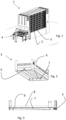
- the in Fig. 1 The block storage arrangement 1 shown has at least one block storage element receiving space 2.
- a loading space (not shown) is arranged below the block storage receiving space 2.
- At least one block storage element 3 is arranged in the block storage receiving space 2.
- the block storage element 3 can be transferred into an interior of the block storage by a storage and retrieval station 4.
- Fig. 2 shows a representation of the block bearing element 3.
- An outlet valve 5 is arranged on one end of the block bearing element 3.
- An inlet funnel 6 is arranged on the top of the block bearing element 3.
- the underside of the block bearing element 3 has a guide or distribution device 7.
- Fig. 3 shows a side view of the block storage element 3.
- a liquid receptacle 8 is arranged in a base of the block storage element 3.
- An overflow 9 is also arranged in the base, which interacts with the guide or distribution device 7.
- FIG. 4 a cross-section of the actuating device 10 and the outlet valve 5 is shown.
- Fig. 4 a non-actuated state in which the actuating device 10 and the outlet valve 5 are separated. Furthermore, the actuating device 10 is arranged outside the container receiving space 2 in the non-actuated state. The outlet valve 5 is actuated by the actuating device 10.
- actuating device 10 actuates the outlet valve 5.
- the outlet valve 5 is fluidically connected to the liquid receptacle 8.
- the actuating device 10 is moved from the non-actuated state to the actuated state and vice versa by a movement mechanism (not shown).
- Fig. 6 shows a flow diagram of the block storage arrangement 1 with several block storage elements 3, which are arranged in a block storage element receiving space 2.
- the arrows shown schematically show a liquid and/or nutrient solution course.
- This exemplary representation also shows a storage container 11, which can be arranged at a top point in the direction of gravity of a liquid and/or nutrient supply device.
- the storage container 11 is fluidically connected to a shut-off valve 12.
- plant containers are arranged in the liquid receptacle 8, in which plants are arranged.
- the plant containers have a fluid-permeable bottom in which plant roots can get caught.
- the plants stabilize themselves through their roots and the bottom of the plant container.
- the plants can also grow on a substrate or the like.
- the block storage element 3 has an overflow 9, which interacts with the guide or distribution device 7.
- the overflow 9 is arranged at a first end of the guide or distribution device 7, and the inlet funnel 6 is arranged at a second end of the guide or distribution device 7.
- the liquid intake 8 also has a guide structure that guides the liquid and/or nutrient solution from the inlet funnel 6 to the overflow 9.
- the guide structure ensures that the liquid and/or nutrient solution reaches a large part of the liquid intake 8 before the liquid and/or nutrient solution reaches the overflow 9.
- the block storage element 3 also has an outlet valve 5. Starting from the lowest block storage element 3, the liquid and/or nutrient solution is transferred by a pump (not shown) into, for example, a processing device (not shown) or the storage container 11.
- the block storage element 3 is filled with seeds, seedlings or plants and transferred to the storage and retrieval station 4.
- the storage and retrieval station 4 forms an entrance and exit to the block storage arrangement 1.
- the storage and retrieval station 4 can be connected to the loading room by a lock arrangement (not shown).
- the block storage element 3 is transferred via the loading room into the block storage element receiving room 2.
- the block storage element 3 is transferred to the block storage 1 through a storage and retrieval station 4 and is also removed from there again.
- the storage and retrieval station 4 is connected to the loading room by a lock (not shown).
- the lock is in turn connected to the loading room, which is arranged below at least one block storage element receiving room 2.
- a movable loading vehicle is arranged in the loading room, which transfers the block storage element 3 from the lock to a container receiving room 2. To do this, the loading vehicle picks up the block storage element 3 from the lock by the loading vehicle picking up the block storage element 3 from below, in the direction of gravity, whereby the block storage element 3 is arranged on the loading vehicle.
- the loading vehicle then moves together with the block storage element 3 to the block storage element receiving room 2 in which the block storage element 3 is to be stored. Once there, the loading vehicle lifts the block storage element 3 upwards against the direction of the shear force. If one or more block storage elements 3 are already arranged in the block storage element receiving space 2 to be filled, the loading vehicle lifts the block storage element 3 to be stored together with the block storage elements 3 arranged above it and thus forms a block storage element stack. As soon as the block storage element stack is Once the loading vehicle has been lifted above a certain height, holding elements (not shown) that hold the block storage element stack move so that the loading vehicle can be lowered again without the block storage element 3. The loading vehicle is now free and can store or retrieve further block storage elements 3.
- the loading vehicle positions itself below the block storage element 3 to be removed and lifts this or the block storage element stack so that the holding element moves into a release position.
- the loading vehicle then lowers the block storage element stack.
- the holding elements move back into a holding position and hold the remaining block storage element stack in the block storage element receiving space 2.
- the lowest block storage element 3 of the block storage element stack is now arranged on the loading vehicle, which transfers the block storage 3 to the lock arrangement (lock). From there, the block storage element 3 can be transported further, serviced, repaired, re-stored or the like.
- the process of storing the block storage element 3 is repeated until a desired number of block storage elements 3 are arranged in the block storage element receiving space 2.
- the liquid and/or nutrient supply device can supply the block storage elements 3 with liquid and/or nutrient solutions (hereinafter referred to as liquid).
- liquid is transferred from the storage container 11 via the shut-off valve 12 into the liquid receptacle 8 of a first block storage element 3.
- the first block storage element 3 is the uppermost block storage element 3 of a block bearing element stack.
- a liquid level in the liquid receptacle 8 rises until the liquid flows over the overflow 9. From the overflow 9, the liquid flows via the guide or distribution device 7 into the inlet funnel 6 of the second block bearing element 3 located underneath.
- the guide or distribution device 7 can have a channel, a hose, a pipe or the like. The process is now repeated until all liquid receptacles 8 of the block bearing elements 3 within the block bearing element receiving space 2 are supplied with sufficient liquid. This results in a liquid flow through the liquid receptacle 8 because the overflow 9 and the inlet funnel 6 are arranged away from one another. The liquid therefore floods the entire liquid receptacle 8 before the liquid can flow out through the overflow 9.
- the overflow 9 and the inlet funnel 6 are preferably arranged at different ends of the liquid receptacle 8.
- the outlet valve 5 of the lowest block bearing element 3 cooperates at least temporarily with the actuating device 10. This prevents the liquid from flowing out via the overflow 9 of the lowest block bearing element 3.
- the liquid level is lowered in time before the liquid overflows in the liquid receptacle 8 of the lowest block bearing element 3.
- the collected liquid is fed to a processing device (not shown) and from there transferred back to the storage container 11 or other components.
- the liquid is conveyed by a pump (not shown).
- the pump can also be arranged at a different location, for example after the processing or in the area of the storage container 11.
- the shut-off valve 12 is closed again. This means that no further liquid can enter the block storage elements 3 or the liquid intake 8.
- the shut-off valve 12 can be opened again at intervals to restore the liquid level that was lowered by the plants or fungi.
- the outlet valve 5 can be opened by the actuating device 10 as soon as the liquid has reached a certain height in the liquid intake 8. This can prevent unintentional drainage through the overflow 9.
- a continuous, constant circulation of the liquid and/or nutrient supply device is also possible, but not always necessary.
- the liquid in the lowest block storage element 3 is completely or partially drained by a combination of the outlet valve 5 and the actuating device 10. This makes the block storage element 3 easier to handle because, on the one hand, the block storage element 3 is lighter and, on the other hand, the risk of liquid spilling over is reduced.
- the block storage element 3 can be removed from storage in its empty state. To do this, the block storage element 3 is removed downwards as described above and passed through the lock to the storage and retrieval station 4. From there, the block storage element 3 can be further processed or transported further. Furthermore, the block storage element 3 can be serviced in a removed state, for example by renewing or replacing the outlet valve 5.
- liquid intake 8 Depending on whether the plants are to be harvested, transplanted or transported, a certain level of liquid can remain in the liquid intake 8. This ensures that the plants remain in contact with the liquid during transport, which means that they last longer.
Landscapes
- Life Sciences & Earth Sciences (AREA)
- Environmental Sciences (AREA)
- Mycology (AREA)
- Soil Sciences (AREA)
- Hydroponics (AREA)
Description
- Die Erfindung betrifft ein Blocklagerelement, das zur Vermehrung pflanzlicher oder pilzlicher Biomasse dient und stapelbar ist.
- Weiterhin betrifft die Erfindung eine Blocklageranordnung mit einem Blocklagerelementaufnahmeraum, in dem wenigstens ein Blocklagerelement angeordnet ist.
- Weiterhin betrifft die Erfindung ein Verfahren zur Entnahme eines Blocklagerelementes.
-
FR 2 761 575 A1 -
GB 2541687 A -
KR 101 479 977 B1 -
US 2019/246571 A1 betrifft eine Blocklageranordnung zur Pflanzenaufzucht. - Bekannte Blocklagerelemente dienen lediglich zur Einlagerung, zum Lagern und zur Auslagerung von Lagergut in einem Blocklager. Neben einer reinen Lagertätigkeit weist das Blocklager und das Blocklagerelement keine weiteren Funktionen auf.
- Ein Blocklager bzw. eine Blocklageranordnung beschreibt eine Lageranordnung mit wenigstens einem Blocklagerelementaufnahmeraum. In den Blocklagerelementaufnahmeraum können stapelbare Blocklagerelemente ein- und ausgelagert werden können. Dazu wird wenigstens ein Blocklagerelement durch einen Beschickungsraum in den Blocklagerelementaufnahmeraum ein- oder ausgelagert. Der Beschickungsraum kann in Schwerkraftrichtung oberhalb oder unterhalb des Blocklagerelementaufnahmeraums angeordnet sein, sodass eine Ein- oder Auslagerrichtung in Schwerkraftrichtung oder entgegengesetzt der Schwerkraftrichtung orientiert ist. Die Ein- und Auslagerrichtung wird durch die Anordnung des Beschickungsraums festgelegt. Ist der Beschickungsraum oberhalb des Blocklagerelementaufnahmeraums angeordnet, so ist die Einlagerrichtung in Schwerkraftrichtung und die Auslagerrichtung entgegen der Schwerkraftrichtung. Ist der Beschickungsraum in Schwerkraftrichtung unterhalb des Blocklagerelementaufnahmeraums angeordnet, so ist die Einlagerrichtung entgegen der Schwerkraftrichtung orientiert und die Auslagerrichtung in der Schwerkraftrichtung orientiert. Werden mehrere Blocklagerelemente in dem Blocklagerelementaufnahmeraum eingelagert entsteht ein Blocklagerelementstapel. Weitere Bezeichnungen für das Blocklager sind Stapellager oder Behälterstapellager. Im vorliegenden Ausführungsbeispiel ist der Blocklagerelementaufnahmeraum in Schwerkraftrichtung oberhalb des Beschickungsraums angeordnet.
- Es ist die Aufgabe der vorliegenden Erfindung, die Funktionalität eines Blocklagerelementes zu erhöhen.
- Diese Aufgabe wird durch die Merkmale des Anspruchs 1 gelöst.
- Das Blocklagerelement der eingangsgenannten Art weist eine Flüssigkeitsaufnahme mit einem Überlauf auf. Durch diese Anordnung kann das Blocklagerelement zur Vermehrung von pflanzlicher oder pilzlicher Biomasse oder dessen Zucht benutzt werden. Durch die Flüssigkeitsaufnahme können Pflanzen in verschiedenen Stadien, wie Samen, Setzlinge oder dergleichen oder auch Pilze mit Flüssigkeit versorgt werden. Durch die Anordnung der Pflanzen oder Pilze an der Flüssigkeitsaufnahme werden diese mit Flüssigkeit und/oder Nährstofflösung versorgt. Pflanzen können oberhalb der Flüssigkeitsaufnahme angeordnet sein und mit ihren Wurzeln in die Flüssigkeitsaufnahme reichen. Die Pflanzen können somit über ihre Wurzeln aus der Flüssigkeitsaufnahme Flüssigkeit ziehen. Dazu können Pflanzen oder Pilze in Behältern angeordnet sein, die einen fluiddurchlässigen Boden aufweisen. In dem Boden können sich weiterhin Wurzeln der Pflanzen verhaken. Weiterhin kann durch den Überlauf überschüssige Flüssigkeit aus der Flüssigkeitsaufnahme abgeleitet werden. Dadurch kann keine Staunässe entstehen, die in der Flüssigkeitsaufnahme befindlichen Pflanzen und/oder Pilzen schaden könnte. Die Pflanzen und/oder Pilze finden somit optimale Wachstumsbedingungen vor. Neben einer Reduktion der Staunässe kann durch den Überlauf des Blocklagerelementes ein darunter befindliches Blocklagerelement mit einer Flüssigkeit und/oder Nährstofflösung versorgt werden. Somit benötigt ein Blocklagerelementstapel nur einen Flüssigkeits- und/oder Nährstofflösungszulauf, was zu geringen Kosten führt. Durch diese Anordnung kann das Blocklagerelement in einem Blocklager eingelagert werden und zur Vermehrung von Biomasse dienen. Die Funktionalität des Blocklagerelementes wird erhöht. Weiterhin kann durch eine solche Anordnung eine Vielzahl von Pflanzen und/oder Pilze in einem relativ engen Raum wachsen.
- Vorzugsweise wirkt der Überlauf mit einer Leit- oder Verteileinrichtung zusammen. Durch die Leit- oder Verteileinrichtung wird verhindert, dass durch den Überlauf abgeleitete Flüssigkeit und/oder Nährstofflösung im darunter befindliches Blocklagerelement direkt wieder in den Überlauf gelangt. Die so abgeleitete Flüssigkeit und/oder Nährstofflösung versorgt also das darunter befindliche Blocklagerelement in einer optimalen Weise. Dabei kann das Blocklagerelement eine Wanne aufweisen, wobei die Wanne eine Leitstruktur aufweisen kann, die die Flüssigkeit und/oder Nährstofflösung leitet. Die Leitstruktur kann sicherstellen, dass die Flüssigkeit und/oder Nährstofflösung gleichmäßig in der Wanne verteilt werden kann, bevor die Flüssigkeit und/oder durch den Überlauf ins nächste Blocklagerelement gelangen kann. Die Leit- oder Verteileinrichtung kann beispielsweise eine Rinne, analog zu einer Regenrinne, aufweisen.
- Das Blocklagerelement weist ein Auslassventil auf. Durch das Auslassventil kann in einem Auslagerungsprozess die Flüssigkeit und/oder Nährstofflösung abgelassen werden. Dadurch wird während dem Auslagerungsprozess die Gefahr eines überschwappen verhindert, wodurch das Blocklagerelement leichter handhaben lässt. Weiterhin kann das Auslassventil überschüssige Flüssigkeit und/oder Nährstofflösung ableiten, die während eines Bewässerungsprozesses in das Blocklagerelement eingeführt wird. Die aufgefangene Flüssigkeit und/oder Nährstofflösung kann aufbereitet und wieder benutzt werden.
- Vorzugsweise weist das Blocklagerelement einen Einlasstrichter auf. Durch den Einlasstrichter wird von der Leit- oder Verteileinrichtung geleitete Flüssigkeit und/oder Nährstofflösung aufgefangen und gezielt der Flüssigkeitsaufnahme zugeführt. Mögliche strömungsbedingte Erosionen und Ausspülung von Trägermaterial kann dadurch verhindert werden. Weiterhin kann durch den Einlasstrichter die Flüssigkeit und/oder Nährstofflösung gezielt verteilt werden um alle in dem Blocklagerelement angeordneten Pflanzen oder Pilze optimal mit der Flüssigkeit und/oder Nährstofflösung zu versorgen.
- Vorzugsweise sind der Einlasstrichter und der Überlauf in verschiedenen Bereichen Blocklagerelementes angeordnet. Flüssigkeits- und/oder Nährstofflösung, die über den Überlauf abläuft, werden von der Leit- oder Verteileinrichtung zu dem Einlasstrichter des darunter befindlichen Blocklagerelementes geleitet. Dadurch, dass der Einlasstrichter und der Überlauf in verschiedenen Bereichen Blocklagerelementes angeordnet ist, muss die Flüssigkeit und/oder Nährstofflösung eine gewisse Strecke zurücklegen, bevor die Flüssigkeit und/oder Nährstofflösung wieder zu dem Überlauf gelangt. Dadurch wird eine Versorgung mit der Flüssigkeit und/oder Nährstofflösung der gesamten Flüssigkeitsaufnahme ermöglicht, sodass alle Pflanzen und/oder Pilze, die der Flüssigkeitsaufnahme angeordnet sind versorgt sind.
- Die Aufgabe wird dadurch gelöst, dass eine Blocklageranordnung mit einem Blocklagerelementaufnahmeraum, in dem wenigstens ein Blocklagerelement angeordnet ist, wenigstens eine Flüssigkeits- und/oder Nährstoffversorgungsvorrichtung aufweist. Durch diese Anordnung kann das Blocklagerelement mit Flüssigkeit und oder Nährstofflösung versorgt werden. Die Flüssigkeits- und/oder Nährstoffversorgungsvorrichtung übernimmt die Versorgung der Pflanzen und/oder Pilze, so dass menschliche Arbeit entfällt. Dadurch werden laufende Kosten reduziert und eine stete Versorgung mit Flüssigkeit und/oder Nährstoffen ist gewährleistet.
- Vorzugsweise weist die Flüssigkeits- und/oder Nährstoffversorgungsvorrichtung wenigstens ein Absperrventil auf. Durch dieses Absperrventil kann ein Zulauf in die Flüssigkeitsaufnahme des Blocklagerelementes gesteuert werden. Je nach Bedarf kann die Flüssigkeit und/oder Nährstofflösung zugeführt werden. Dadurch wird eine Über- oder Unterversorgung vermieden. Weiterhin kann für jede Pflanzenart und/oder Pilzart optimale Bedingungen geschafft werden, sodass die Pflanzen und/oder Pilze optimale Wachstumsbedingungen vorfinden.
- Die Flüssigkeits- und/oder Nährstoffversorgungsvorrichtung weist eine Betätigungseinrichtung für das Auslassventil auf. Durch diese Betätigungseinrichtung wird das Auslassventil an dem Blocklagerelement betätigt, wodurch abzuleitende Flüssigkeit und/oder Nährstofflösung abgelassen werden kann. Durch diese Betätigungseinrichtung kann das Auslassventil relativ einfach gehalten werden kann, da es rein mechanisch betätigt werden kann.
- Vorzugsweise weist die Flüssigkeit- und/oder Nährstoffversorgung Vorrichtung einen Vorratsbehälter auf. Der Vorratsbehälter kann oberhalb in Schwerkraftrichtung oder in einem oberen Bereich des Blocklagerelementaufnahmeraum angeordnet sein, wodurch die Flüssigkeit und/oder Nährstofflösung schwerkraftbedingt in unterhalb angeordnete Flüssigkeitsaufnahme überführt werden kann.
- Vorzugsweise weist die Flüssigkeits- und/oder Nährstoffversorgungsvorrichtung eine Pumpe auf. Die Pumpe kann die Flüssigkeit und/oder Nährstofflösung durch die Flüssigkeits- und/oder Nährstoffversorgungvorrichtung pumpen. Somit ist man nicht auf die Wirkung der Schwerkraft angewiesen und kann die Flüssigkeit und/oder Nährstofflösung auch entgegen der Schwerkraft fördern. Beispielsweise kann durch die Pumpe aufgefangene Flüssigkeit und/oder Nährstofflösung ausgehend von der Betätigung in den Vorratsbehälter überführen.
- Vorzugsweise stehen zumindest zwei Elemente der Flüssigkeits- und/oder Nährstoffversorgungsvorrichtung in fluidischer Verbindung. So kann beispielsweise die Betätigungseinrichtung mit der Pumpe in fluidischer Verbindung stehen, und die Pumpe wiederum mit dem Vorratsbehälter. Dadurch kann überschüssige Flüssigkeit und/oder Nährstofflösung zurück in den Vorratsbehälter überführt werden. Weiterhin kann der Vorratsbehälter mit dem Absperrventil in fluidischer Verbindung stehen. Somit kann die Flüssigkeit und/oder Nährstofflösung durch die fluidische Verbindung gefördert werden. Durch die fluidische Verbindung ist ein einfaches Überführen der Flüssigkeit und/oder Nährstofflösung möglich.
- Die Aufgabe wird bei einem Verfahren der eingangs genannten Art dadurch gelöst, dass ein maximal bis zum Überlauf mit Flüssigkeit gefüllte Flüssigkeitsaufnahme eines Blocklagerelementes vor einer Entnahme entleert wird. Dadurch wird ein Blocklagerelement mit einer relativ leeren Flüssigkeitsaufnahme ausgelagert, sodass das Gewicht des Blocklagerelementes reduziert wird. Dies ermöglicht neben einem geringeren Schwapprisiko eine leichte Handhabung des Blocklagerelementes.
- Vorzugsweise werden die Blocklagerelemente sequenziell entleert und entnommen. Durch die sequenzielle Entleerung und Entnahme der Blocklagerelemente kann ein Blocklagerelementstapel mit nur einer Betätigungseinrichtung entleert werden. Dies reduziert die Kosten, sowohl Produktionskosten als auch Wartungskosten. Pro Blocklagerelementaufnahmeraum weist das Blocklager nur eine Betätigungseinrichtung auf. Die Peripherie, wie den Vorratsbehälter, die Aufbereitung, Pumpe oder dergleichen kann mit einen oder mehr Blocklagerelementaufnahmeräume zusammenwirken. Dies hält einen Aufbau des Blocklagers einfach. Vorzugsweise wird von einem Stapel zu entnehmender Blocklagerelemente jeweils das unterste Blocklagerelement entleert und entnommen. Durch die Entnahme des untersten Blocklagerelements benutzt man die Schwerkraft, um die Flüssigkeit und/oder Nährstofflösung zu entnehmen. Dadurch wird eine reine Fließbewegung der Flüssigkeit ermöglicht und Pumpvorgänge entfallen.
- Vorzugsweise wirkt das Absperrventil und Auslassventil zum Entleeren zusammen. Damit keine neue Flüssigkeit und/oder Nährstofflösung während eines Entleerungsvorganges nachfließt, wirken das Absperrventil und Auslassventil zusammen. Der Entleerungsvorgang wird somit zeitlich verkürzt, was die Entnahmezeiten ebenfalls verkürzt.
- Die Erfindung wird im Folgenden anhand eines bevorzugten Ausführungsbeispiels in Verbindung mit der Zeichnung beschrieben. Hierin zeigen:
- Fig. 1
- eine Blocklageranordnung;
- Fig. 2
- ein Blocklagerelement;
- Fig. 3
- eine Seitenansicht des Blocklagerelementes;
- Fig. 4
- einen Querschnitt eines Auslassventils und einer Betätigungseinrichtung in einem nicht betätigten Zustand;
- Fig. 5
- einen Querschnitt eines Auslassventils sind eine Betätigungseinrichtung in einen betätigten Zustand; und
- Fig. 6
- ein Fließbild der Blocklageranordnung.
- Die in
Fig. 1 dargestellte Blocklageranordnung 1 weist wenigstens einen Blocklagerelementaufnahmeraum 2 auf. Unterhalb des Blocklageraufnahmeraumes 2 ist ein nicht dargestellter Beschickungsraum angeordnet. In dem Blocklageraufnahmeraum 2 ist wenigstens ein Blocklagerelement 3 angeordnet. Das Blocklagerelement 3 kann durch eine Einlager- und Auslagerstation 4 in ein Inneres des Blocklagers überführt werden. -
Fig. 2 zeigt eine Darstellung des Blocklagerelements 3. An einer Stirnseite des Blocklagerelementes 3 ist ein Auslassventil 5 angeordnet. Auf der Oberseite des Blocklagerelementes 3 ist ein Einlasstrichter 6 angeordnet. Die Unterseite des Blocklagerelementes 3 weist eine Leit- oder Verteileinrichtung 7. -
Fig. 3 stellt eine Seitenansicht des Blocklagerelementes 3 dar. Eine Flüssigkeitsaufnahme 8 ist in einem Boden des Blocklagerelementes 3 angeordnet. In dem Boden ist weiterhin ein Überlauf 9 angeordnet, der mit der Leit- oder Verteileinrichtung 7 zusammenwirkt. - In den
Figuren 4 und 5 ist ein Querschnitt der Betätigungseinrichtung 10 und des Auslassventils 5 dargestellt. Dabei zeigtFig. 4 einen nicht betätigten Zustand, in dem die Betätigungseinrichtung 10 und das Auslassventil 5 getrennt sind. Weiterhin ist die Betätigungseinrichtung 10 in dem nicht betätigten Zustand außerhalb des Behälteraufnahmeraums 2 angeordnet. Das Auslassventil 5 ist durch die Betätigungseinrichtung 10 betätigt. - In
Fig. 5 ist ein betätigter Zustand dargestellt, in dem die Betätigungseinrichtung 10 das Auslassventil 5 betätigt. Das Auslassventil 5 ist fluidisch mit der Flüssigkeitsaufnahme 8 verbunden. Die Betätigungseinrichtung 10 wird durch einen nicht dargestellten Bewegungsmechanismus von dem nicht betätigten Zustand in den betätigten Zustand und umgekehrt bewegt. -
Fig. 6 zeigt ein Fließbild der Blocklageranordnung 1 mit mehreren Blocklagerelementen 3, die in einem Blocklagerelementaufnahmeraum 2 angeordnet sind. Die dargestellten Pfeile zeigen schematisch einen Flüssigkeit- und/oder Nährstofflösungsverlauf Diese beispielhafte Darstellung zeigt weiterhin einen Vorratsbehälter 11, der an einem in Schwerkraftrichtung obersten Punkt einer Flüssigkeits- und/oder Nährstoffversorgungsvorrichtung angeordnet sein kann. Der Vorratsbehälter 11 ist mit einem Absperrventil 12 fluidisch verbunden. In der Flüssigkeitsaufnahme 8 sind in diesem Beispiel Pflanzbehälter angeordnet, in denen wiederum Pflanzen angeordnet sind. Die Pflanzbehälter weisen einen fluiddurchlässigen Boden auf, indem sich Pflanzenwurzeln verhaken können. Die Pflanzen stabilisieren sich durch ihre Wurzeln und dem Boden des Pflanzbehälters. Die Pflanzen können auch auf einem Substrat oder dergleichen wachsen. Das Blocklagerelement 3 weist einen Überlauf 9 auf, der mit der Leit- oder Verteileinrichtung 7 zusammenwirkt. Der Überlauf 9 ist an einem ersten Ende der Leit- oder Verteileinrichtung 7 angeordnet, und der Einlasstrichter 6 an einem zweiten Ende der Leit- oder Verteileinrichtung 7 angeordnet. Die Flüssigkeitsaufnahme 8 weist weiterhin eine Leitstruktur auf, die die Flüssigkeit und/oder Nährstofflösung ausgehend von dem Einlasstrichter 6 zum Überlauf 9 leitet. Dabei stellt die Leitstruktur sicher, dass die Flüssigkeit und/oder Nährstofflösung einen Großteil der Flüssigkeitsaufnahme 8 erreicht, bevor die Flüssigkeit und/oder Nährstofflösung zum Überlauf 9 gelangt. Weiterhin weist das Blocklagerelement 3 ein Auslassventil 5 auf. Ausgehend von dem untersten Blocklagerelement 3 wird die Flüssigkeit und/oder Nährstofflösung durch eine nicht dargestellte Pumpe in beispielsweise eine nicht dargestellte Aufbereitungsvorrichtung oder den Vorratsbehälter 11 überführt. - Im Folgenden wird ein beispielhafter Prozess beschrieben ausgehend von einer Einlagerung von dem Blocklagerelement 3 über Wachstumsphasen von Pflanzen, die in einem Pflanzbehälter in der Flüssigkeitsaufnahme 8 angeordnet sind, bis hin zur Auslagerung des Blocklagerelementes 3 samt der in den Pflanzbehälter angeordneter Pflanzen.
- Das Blocklagerelement 3 wird mit Samen, Setzlingen oder Pflanzen bestückt und in die Ein- und Auslagerstation 4 überführt. Die Ein- und Auslagerstation 4 bildet einen Eingang und Ausgang zu der Blocklageranordnung 1. Dabei kann die Ein- und Auslagerstation 4 durch eine nicht dargestellte Schleusenanordnung mit dem Beschickungsraum verbunden sein. Das Blocklagerelement 3 wird über den Beschickungsraum in den Blocklagerelementaufnahmeraum 2 überführt.
- Das Blocklagerelement 3 wird durch eine Ein- und Auslagerstation 4 in das Blocklager 1 überführt und von dort aus auch wieder entnommen. Die Ein- und Auslagerstation 4 ist in der vorliegenden Ausführungsform durch eine nicht dargestellte Schleuse mit dem Beschickungsraum verbunden sein. Die Schleuse ist wiederum mit dem Beschickungsraum verbunden, der unterhalb wenigstens eines Blocklagerelementaufnahmeraums 2 angeordnet ist. In dem Beschickungsraum ist ein bewegbares Beschickungsfahrzeug angeordnet, das das Blocklagerelemente 3 von der Schleuse in einen Behälteraufnahmeraum 2 überführt. Dazu holt das Beschickungsfahrzeug das Blocklagerelement 3 von der Schleuse ab, indem das Beschickungsfahrzeug das Blocklagerelement 3 von unten, in Schwerkraftrichtung aufnimmt, wodurch das Blocklagerelement 3 auf dem Beschickungsfahrzeug angeordnet ist. Anschließend verfährt das Beschickungsfahrzeug samt Blocklagerelement 3 zu dem Blocklagerelementaufnahmeraum 2, in den das Blocklagerelement 3 eingelagert werden soll. Dort angekommen, hebt das Beschickungsfahrzeug das Blocklagerelement 3 entgegen der Scherkraftrichtung nach oben. Sollte bereits ein oder mehr Blocklagerelemente 3 in dem zu befüllenden Blocklagerelementaufnahmeraum 2 angeordnet sein, hebt das Beschickungsfahrzeug das einzulagernde Blocklagerelement 3 samt dem oben oberhalb angeordneten Blocklagerelementen 3 an und formt somit einen Blocklagerelementstapel. Sobald der Blocklagerelementstapel durch das Beschickungsfahrzeug über eine gewisse Höhe gehoben wurde, verschieben sich nicht dargestellte Halteelement, die den Blocklagerelementstapel halten, sodass das Beschickungsfahrzeug ohne das Blocklagerelement 3 wieder senken kann. Das Beschickungsfahrzeug ist nun frei und kann weitere Blocklagerelemente 3 ein- oder auslagern. Während eines Auslagerprozesses kann jeweils nur das unterstes Blocklagerelement 3, eines in einem Blocklagerelementaufnahmeraum 2 angeordneten Blocklagerelementstapels, entnommen werden. Dazu positioniert sich das Beschickungsfahrzeug unterhalb des zu entnehmenden Blocklagerelementes 3 und hebt dieses oder den Blocklagerelementstapel an, sodass sich das Haltelement in eine Freigabeposition verschiebt. Anschließend senkt das Beschickungsfahrzeug den Blocklagerelementstapel. Sobald der Blocklagerelementstapel um eine gewisse Distanz gesenkt wurde verschieben sich die Halteelemente zurück in eine Halteposition und halten den verbleibenden Blocklagerelementstapel in dem Blocklagerelementaufnahmeraum 2. Das unterste Blocklagerelement 3 des Blocklagerelementstapels ist nun auf dem Beschickungsfahrzeug angeordnet, das das Blocklager 3 zu der Schleusenanordnung (Schleuse) überführt. Von dort aus kann das Blocklagerelement 3 weitertransportiert, gewartet, instandgesetzt, wiedereingelagert oder dergleichen werden. Der Vorgang des Einlagerns des Blocklagerelementes 3 wird wiederholt, bis eine gewünschte Zahl von Blocklagerelementen 3 in dem Blocklagerelementaufnahmeraum 2 angeordnet ist.
- Ist nun die gewünschte Zahl von Blocklagerelementen 3 in dem Blocklagerelementaufnahmeraum 2 angeordnet, kann die Flüssigkeits- und/oder Nährstoffversorgungsvorrichtung die Blocklagerelemente 3 mit Flüssigkeit und/oder Nährstofflösungen (im Folgenden Flüssigkeit genannt) versorgen. Dazu wird ausgehend von dem Vorratsbehälter 11 über das Absperrventil 12 Flüssigkeit in die Flüssigkeitsaufnahme 8 eines ersten Blocklagerelementes 3 überführt. In diesem Ausführungsbeispiel ist das erste Blocklagerelement 3 das oberste Blocklagerelement 3 eines Blocklagerelementstapels. Ein Flüssigkeitsspiegel in der Flüssigkeitsaufnahme 8 steigt an, bis die Flüssigkeit über den Überlauf 9 tritt. Von dem Überlauf 9 fließt die Flüssigkeit über die Leit- oder Verteileinrichtung 7 in den Einlasstrichter 6 des sich darunter befindlichen zweiten Blocklagerelements 3. Die Leit- oder Verteileinrichtung 7 kann dabei eine Rinne, einen Schlauch, ein Rohr oder dergleichen aufweisen. Nun wiederholt sich der Vorgang bis alle Flüssigkeitsaufnahmen 8 der Blocklagerelemente 3 innerhalb des Blocklagerelementaufnahmeraums 2 mit ausreichend Flüssigkeit versorgt sind. Es ergibt sich eine Flüssigkeitsströmung durch die Flüssigkeitsaufnahme 8, weil der Überlauf 9 und der Einlasstrichter 6 entfernt voneinander angeordnet sind. Die Flüssigkeit flutet also die komplette Flüssigkeitsaufnahme 8, bevor die Flüssigkeit durch den Überlauf 9 abfließen kann. Vorzugsweise sind der Überlauf 9 und der Einlasstrichter 6 an unterschiedlichen Enden der Flüssigkeitsaufnahme 8 angeordnet.
- Da unterhalb des untersten Blocklagerelementes 3 kein weiteres Blocklagerelement 3 angeordnet ist, würde die Leit- oder Verteileinrichtung 7 nicht weiter funktionieren. Deshalb wirkt das Auslassventil 5 des untersten Blocklagerelementes 3 zumindest zeitweise mit der Betätigungseinrichtung 10 zusammen. Dadurch wird verhindert, dass die Flüssigkeit über den Überlauf 9 des untersten Blocklagerelementes 3 abfließt.
- Durch das Zusammenwirken von dem Auslassventil 5 und der Betätigungseinrichtung 10 wird rechtzeitig vor einem Überlaufen der Flüssigkeit in der Flüssigkeitsaufnahme 8 des untersten Blocklagerelementes 3 der Flüssigkeitsspiegel gesenkt. Die aufgefangene Flüssigkeit wird einer nicht dargestellten Aufbereitungsvorrichtung zugeführt und von dort aus zurück in den Vorratsbehälter 11 oder andere Komponenten überführt. Ausgehend von der Betätigungseinrichtung 10 wird die Flüssigkeit durch eine nicht dargestellte Pumpe gefördert. Die Pumpe kann dabei jedoch auch an einer anderen Stelle, beispielsweise nach der Aufbereitung oder im Bereich des Vorratsbehälter 11 angeordnet sein. Sobald in jeder Flüssigkeitsaufnahme 8 der Blocklagerelemente 3 der Flüssigkeitsspiegel ausreichend gestiegen ist, wird das Absperrventil 12 wieder geschlossen. Dadurch kann keine weitere Flüssigkeit in die Blocklagerelemente 3 bzw. die Flüssigkeitsaufnahme 8 gelangen. In zeitlichen Abständen kann das Absperrventil 12 wieder geöffnet werden, um den Flüssigkeitsspiegel wiederherzustellen, der durch die Pflanzen oder Pilze gesenkt wurde. Ebenso kann das Auslassventil 5 durch die Betätigungseinrichtung 10 geöffnet werden, sobald die Flüssigkeit eine gewisse Höhe in der Flüssigkeitsaufnahme 8 erreicht hat. Ein unbeabsichtigtes Ablaufen durch den Überlauf 9 kann dadurch vermieden werden. Ein durchgehender, beständiger Kreislauf der Flüssigkeits- und/oder Nährstoffversorgungsvorrichtung ist ebenfalls möglich, jedoch nicht immer nötig.
- Um die Blocklagerelemente 3 samt den erntereifen Pflanzen auszulagern, wird in dem jeweils untersten Blocklagerelement 3 durch ein Zusammenwirken des Auslassventil 5 und der Betätigungseinrichtung 10 die Flüssigkeit vollständig oder teilweise abgelassen. Dadurch kann das Blocklagerelement 3 leichter gehandhabt werden, da einerseits das Blocklagerelement 3 weniger Gewicht hat und andererseits die Gefahr einer überschwappenden Flüssigkeit reduziert ist. Das Blocklagerelement 3 kann in seinem entleerten Zustand ausgelagert werden. Dazu wird das Blocklagerelement 3, wie oben beschrieben, nach unten entnommen und durch die Schleuse der Ein- und Auslagerstation 4 übergeben. Von dort aus kann das Blocklagerelement 3 weiterverarbeitet oder weitertransportiert werden. Weiterhin kann einem ausgelagerten Zustand das Blocklagerelement 3 gewartet werden, indem beispielsweise das Auslassventil 5 erneuert bzw. ausgetauscht wird.
- Je nachdem, ob die Pflanzen geerntet, umgesetzt oder transportiert werden sollen, kann ein gewisser Flüssigkeitsspiegel in der Flüssigkeitsaufnahme 8 bleiben. Dadurch bleiben die Pflanzen beim Transport mit der Flüssigkeit in Kontakt, wodurch diese länger haltbar sind.
-
- 1
- Blocklageranordnung
- 2
- Blocklagerelementaufnahmeraum
- 3
- Blocklagerelement
- 4
- Ein- und Auslagerstation
- 5
- Auslassventil
- 6
- Einlasstrichter
- 7
- Leit- oder Verteileinrichtung
- 8
- Flüssigkeitsaufnahme
- 9
- Überlauf
- 10
- Betätigungseinrichtung
- 11
- Vorratsbehälter
- 12
- Absperrventil
Claims (12)
- Blocklageranordnung (1) mit einem Blocklagerelementaufnahmeraum (2) und einem unterhalb des Blocklagerelementaufnahmeraums (2) angeordneten Beschickungsraum, wobei in dem Blocklagerelementaufnahmeraum (2) wenigstens ein Blocklagerelement (3) angeordnet ist, das zur Vermehrung pflanzlicher oder pilzlicher Biomasse dient und stapelbar ist, wobei die Blocklageranordnung (1) wenigstens eine Flüssigkeits- und/oder Nährstoffversorgungsvorrichtung aufweist dadurch gekennzeichnet, dass das Blocklagerelement (3) eine Flüssigkeitsaufnahme (8) mit einem Überlauf (9) aufweist, wobei das Blocklagerelement (3) ein Auslassventil (5) aufweist, und wobei die Flüssigkeits- und/oder Nährstoffversorgungsvorrichtung eine Betätigungseinrichtung (10) für das Auslassventil (5) aufweist, wobei die Betätigungseinrichtung (10) in einem nicht betätigten Zustand außerhalb des Behälteraufnahmeraumes (2) angeordnet ist.
- Blocklageranordnung (1) nach Anspruch 1 dadurch gekennzeichnet, dass der Überlauf (9) mit einer Leit- oder Verteileinrichtung (7) zusammenwirkt.
- Blocklageranordnung (1) nach Anspruch 1 oder 2 dadurch gekennzeichnet, dass das Blocklagerelement (3) einen Einlasstrichter (6) aufweist.
- Blocklageranordnung (1) nach Anspruch 3 dadurch gekennzeichnet, dass der Einlasstrichter (6) und der Überlauf (9) in verschiedenen Bereichen des Blocklagerelements (3) angeordnet sind.
- Blocklageranordnung (1) nach Anspruch 1, dadurch gekennzeichnet, dass die Flüssigkeits- und/oder Nährstoffversorgungsvorrichtung wenigstens ein Absperrventil (12) aufweist.
- Blocklageranordnung (1) nach Anspruch 1 dadurch gekennzeichnet, dass die Flüssigkeits- und/oder Nährstoffversorgungsvorrichtung eine Pumpe aufweist.
- Blocklageranordnung (1) nach einem der Ansprüche 1 bis 6 dadurch gekennzeichnet, dass die Flüssigkeits- und/oder Nährstoffversorgungsvorrichtung einen Vorratsbehälter (11) aufweist.
- Blocklageranordnung (1) nach einem der Ansprüche 1 bis 7 dadurch gekennzeichnet, dass zumindest zwei Elemente der Flüssigkeits- und/oder Nährstoffversorgungsvorrichtung zumindest fluidischer Verbindung stehen.
- Verfahren zur Entnahme eines Blocklagerelementes (3) aus einer Blocklageranordnung (1) nach den Ansprüchen 1 bis 8, wobei ein bis maximal bis zum Überlauf (9) mit Flüssigkeit gefüllte Flüssigkeitsaufnahme (8) eines Blocklagerelementes (3) vor einer Entnahme durch ein Auslassventil (5) entleert wird.
- Verfahren nach Anspruch 9, dadurch gekennzeichnet, dass die Blocklagerelemente (3) sequentiell entleert und entnommen werden.
- Verfahren nach Anspruch 9 oder 10, dadurch gekennzeichnet, dass von einem Stapel zu entnehmender Blocklagerelemente (3) jeweils das unterste Blocklagerelement (3) entleert und entnommen wird.
- Verfahren nach einem der Ansprüche 9 bis 11, dadurch gekennzeichnet, dass das Absperrventil (12) und das Auslassventil (5) zum Entleeren zusammenwirken.
Priority Applications (6)
| Application Number | Priority Date | Filing Date | Title |
|---|---|---|---|
| ES20172794T ES3025801T3 (en) | 2020-05-04 | 2020-05-04 | Block bearing element with liquid receptacle and overflow |
| PL20172794.8T PL3906776T3 (pl) | 2020-05-04 | 2020-05-04 | Element do składowania w stosach z funkcją transportu cieczy i przelewem |
| EP20172794.8A EP3906776B1 (de) | 2020-05-04 | 2020-05-04 | Blocklagerelement mit flüssigkeitsübernahme und überlauf |
| CN202110483669.0A CN113661848B (zh) | 2020-05-04 | 2021-04-30 | 带有液体接收部和溢流口的块支架元件 |
| US17/306,590 US20210337750A1 (en) | 2020-05-04 | 2021-05-03 | Block storage element with fluid transfer and overflow mechanism |
| CA3117246A CA3117246A1 (en) | 2020-05-04 | 2021-05-03 | Block storage element with fluid transfer and overflow mechanism |
Applications Claiming Priority (1)
| Application Number | Priority Date | Filing Date | Title |
|---|---|---|---|
| EP20172794.8A EP3906776B1 (de) | 2020-05-04 | 2020-05-04 | Blocklagerelement mit flüssigkeitsübernahme und überlauf |
Publications (2)
| Publication Number | Publication Date |
|---|---|
| EP3906776A1 EP3906776A1 (de) | 2021-11-10 |
| EP3906776B1 true EP3906776B1 (de) | 2025-02-19 |
Family
ID=70861192
Family Applications (1)
| Application Number | Title | Priority Date | Filing Date |
|---|---|---|---|
| EP20172794.8A Active EP3906776B1 (de) | 2020-05-04 | 2020-05-04 | Blocklagerelement mit flüssigkeitsübernahme und überlauf |
Country Status (6)
| Country | Link |
|---|---|
| US (1) | US20210337750A1 (de) |
| EP (1) | EP3906776B1 (de) |
| CN (1) | CN113661848B (de) |
| CA (1) | CA3117246A1 (de) |
| ES (1) | ES3025801T3 (de) |
| PL (1) | PL3906776T3 (de) |
Families Citing this family (1)
| Publication number | Priority date | Publication date | Assignee | Title |
|---|---|---|---|---|
| EP4062748B1 (de) * | 2021-03-25 | 2026-01-28 | Jungheinrich Aktiengesellschaft | Flüssigkeitsversorgung eines blocklagerelementes |
Citations (2)
| Publication number | Priority date | Publication date | Assignee | Title |
|---|---|---|---|---|
| KR101479977B1 (ko) * | 2013-09-26 | 2015-01-09 | 에프에이테크 주식회사 | 가정용 수족관 겸용 수경재배장치 |
| US20190246571A1 (en) * | 2016-09-15 | 2019-08-15 | Ocado Innovation Limited | Growing systems and methods |
Family Cites Families (32)
| Publication number | Priority date | Publication date | Assignee | Title |
|---|---|---|---|---|
| US2867945A (en) * | 1955-10-19 | 1959-01-13 | Harold B Gotaas | Process of photosynthetic conversion of organic waste by algal-bacterial symbiosis |
| GB1597111A (en) * | 1976-11-18 | 1981-09-03 | Kenneth Roy Dunn | Hydroponic cultivation of plants |
| US4334386A (en) * | 1980-06-16 | 1982-06-15 | Douglas Arthur Burcombe | Soiless gardening system |
| DK402183A (da) * | 1982-10-05 | 1984-04-06 | Bellaplast Gmbh | Transport-, lager og salgsbeholder |
| FR2553970B1 (fr) * | 1983-10-27 | 1989-04-28 | Allibert Sa | Caisse pour la culture hydroponique de plantes |
| US5095649A (en) * | 1990-10-16 | 1992-03-17 | Flo-Step, Inc. | Storage receptacle assembly |
| GB9216507D0 (en) * | 1992-08-04 | 1992-09-16 | Mcdowell Thomas J | Apparatus for the cultivation of plants |
| JPH1056884A (ja) * | 1996-08-20 | 1998-03-03 | Ishii Ind Co Ltd | 箱体積載装置 |
| FR2761575B1 (fr) * | 1997-04-07 | 1999-09-10 | Gode Et Fils R | Bac de forcage hydroponique pour la culture des endives et installation de forcage hydroponique |
| FR2761574B1 (fr) * | 1997-04-07 | 1999-06-18 | Gode Et Fils R | Bac de forcage hydroponique pour la culture des endives, piece tubulaire pour un tel bac et installation de forcage hydroponique |
| CA2391552A1 (en) * | 2002-06-25 | 2003-12-25 | Paul Houweling | Apparatus and methods for handling and controlling the nurturing of plants |
| US8151518B2 (en) * | 2008-06-17 | 2012-04-10 | New York Sun Works | Vertically integrated greenhouse |
| JP2011234640A (ja) * | 2010-05-07 | 2011-11-24 | Ccs Inc | 植物育成装置 |
| KR20120007420A (ko) * | 2010-07-14 | 2012-01-20 | 조태인 | 적층 서랍식 식물재배기 |
| JP5734055B2 (ja) * | 2011-03-31 | 2015-06-10 | 株式会社椿本チエイン | 植物栽培装置 |
| JP6013724B2 (ja) * | 2011-11-30 | 2016-10-25 | 大和ハウス工業株式会社 | 植物栽培装置 |
| CN202364647U (zh) * | 2011-12-27 | 2012-08-08 | 湖南省湘晖农业技术开发有限公司 | 一种多层育苗架营养液自动补给装置 |
| CA2861881C (en) * | 2012-01-30 | 2019-12-03 | Affinor Growers Inc. | Method and apparatus for automated horticulture and agriculture |
| GB2541687A (en) * | 2015-08-26 | 2017-03-01 | Barnett Patricia | A display or storage apparatus |
| CN205124605U (zh) * | 2015-10-30 | 2016-04-06 | 河北联兴佳垚农业科技有限公司 | 一种芽球玉兰软化床 |
| US10973186B2 (en) * | 2015-11-11 | 2021-04-13 | EZ-Clone Enterprises, Inc. | Aeroponics system with rack and tray |
| DE102016112399B3 (de) * | 2016-07-06 | 2017-07-13 | Hans Hurt | Stapelbarer Behälter |
| US11304390B2 (en) * | 2017-05-08 | 2022-04-19 | Urban Planter, Llc | Automated vertical plant cultivation system |
| WO2019018010A1 (en) * | 2017-07-18 | 2019-01-24 | Eco Convergence Group, Inc. | APPARATUS, SYSTEM AND METHOD FOR HYDROPONIA |
| CN107750935B (zh) * | 2017-10-10 | 2021-07-20 | 福建省中科生物股份有限公司 | 栽培装置、多层立体栽培系统及植物工厂种植系统 |
| GB2556469B (en) * | 2017-11-21 | 2018-11-21 | Adam Dennis Harrison Todd | Hydroponic system and method |
| CN208480432U (zh) * | 2018-05-03 | 2019-02-12 | 重庆市开州区允先生态农业开发有限责任公司 | 适用于无土栽培的花盆 |
| CN109042282A (zh) * | 2018-08-17 | 2018-12-21 | 江苏师范大学 | 循环曝气水培排架 |
| WO2020178734A1 (en) * | 2019-03-06 | 2020-09-10 | Palram 4U Ltd | Hydroponic systems and methods and growing cassettes therefor |
| CN110100716A (zh) * | 2019-05-10 | 2019-08-09 | 江苏师范大学 | 一种可升降循环曝气水培排架 |
| US20210007306A1 (en) * | 2019-07-12 | 2021-01-14 | Harvest2o LLC | Hydroponic system for growing multiple types of plants |
| CN110626805A (zh) * | 2019-09-17 | 2019-12-31 | 华南农业大学 | 一种输送链式育苗穴盘堆叠装置与方法 |
-
2020
- 2020-05-04 EP EP20172794.8A patent/EP3906776B1/de active Active
- 2020-05-04 PL PL20172794.8T patent/PL3906776T3/pl unknown
- 2020-05-04 ES ES20172794T patent/ES3025801T3/es active Active
-
2021
- 2021-04-30 CN CN202110483669.0A patent/CN113661848B/zh active Active
- 2021-05-03 US US17/306,590 patent/US20210337750A1/en active Pending
- 2021-05-03 CA CA3117246A patent/CA3117246A1/en active Pending
Patent Citations (2)
| Publication number | Priority date | Publication date | Assignee | Title |
|---|---|---|---|---|
| KR101479977B1 (ko) * | 2013-09-26 | 2015-01-09 | 에프에이테크 주식회사 | 가정용 수족관 겸용 수경재배장치 |
| US20190246571A1 (en) * | 2016-09-15 | 2019-08-15 | Ocado Innovation Limited | Growing systems and methods |
Also Published As
| Publication number | Publication date |
|---|---|
| EP3906776A1 (de) | 2021-11-10 |
| CN113661848B (zh) | 2025-11-14 |
| ES3025801T3 (en) | 2025-06-09 |
| CA3117246A1 (en) | 2021-11-04 |
| CN113661848A (zh) | 2021-11-19 |
| PL3906776T3 (pl) | 2025-05-26 |
| US20210337750A1 (en) | 2021-11-04 |
Similar Documents
| Publication | Publication Date | Title |
|---|---|---|
| DE2319444A1 (de) | Verfahren zum verpflanzen von keimlingen sowie vorrichtung zur durchfuehrung desselben | |
| EP1890560A2 (de) | Tunnelpasteur | |
| DE202021102469U1 (de) | Vorrichtung zum Anbau von landwirtschaftlichen Erzeugnissen und Zierpflanzen | |
| EP0803188A2 (de) | Aufzuchtbehälter für Pflanzen oder Gemüse | |
| EP3906776A1 (de) | Blocklagerelement mit flüssigkeitsübernahme und überlauf | |
| EP3906777B1 (de) | Gewächshausanordnung | |
| DE2340692A1 (de) | Fahrbares geraet zum selbsttaetigen aufnehmen, speichern und abgeben von stueckguetern, insbesondere heu- oder strohballen | |
| DE102014014244B4 (de) | Verfahren und Einrichtung zur Beerntung von aquatischen Pflanzenkulturen in gestapelten Kulturwannen | |
| DE102008037958A1 (de) | Quallenbecken | |
| DE2709275A1 (de) | Saugreiniger | |
| EP4062754B1 (de) | Blocklageranordnung | |
| DE3415716A1 (de) | Pflanzentrog fuer gewaechshaeuser | |
| DE3419983C2 (de) | Transportbehälter für wasserlösliche Salze | |
| DE3625674C1 (en) | Device for transporting and depositing plants arranged in pots or the like | |
| WO1990011254A1 (de) | Abwasserreinigungseinrichtung | |
| DE2165612C3 (de) | Kühlfischereifahrzeug | |
| EP4062750B1 (de) | Gewächshausanordnung | |
| EP3883363B1 (de) | Gewächshausanlage | |
| DE102022100966A1 (de) | Bestückungswagen für Pflanzenaufzuchtschränke | |
| EP3718394A1 (de) | Vertikalbeet aus stapelbaren pflanzmodulen | |
| DE4325010A1 (de) | Verfahren zum Schlammabzug aus Absetzbecken und Teichen | |
| DE1442184A1 (de) | Laeuterbottich | |
| DE2640114A1 (de) | Anlage fuer die zucht von pflanzen in mit einer fluessigkeit berieselten behaeltern | |
| DE10322526A1 (de) | Grabbewässerung | |
| DE102022113714A1 (de) | Aquaponiksystem zur Kultivierung von Spargel |
Legal Events
| Date | Code | Title | Description |
|---|---|---|---|
| PUAI | Public reference made under article 153(3) epc to a published international application that has entered the european phase |
Free format text: ORIGINAL CODE: 0009012 |
|
| STAA | Information on the status of an ep patent application or granted ep patent |
Free format text: STATUS: REQUEST FOR EXAMINATION WAS MADE |
|
| 17P | Request for examination filed |
Effective date: 20210330 |
|
| AK | Designated contracting states |
Kind code of ref document: A1 Designated state(s): AL AT BE BG CH CY CZ DE DK EE ES FI FR GB GR HR HU IE IS IT LI LT LU LV MC MK MT NL NO PL PT RO RS SE SI SK SM TR |
|
| B565 | Issuance of search results under rule 164(2) epc |
Effective date: 20201019 |
|
| STAA | Information on the status of an ep patent application or granted ep patent |
Free format text: STATUS: EXAMINATION IS IN PROGRESS |
|
| 17Q | First examination report despatched |
Effective date: 20230221 |
|
| P01 | Opt-out of the competence of the unified patent court (upc) registered |
Effective date: 20230628 |
|
| GRAP | Despatch of communication of intention to grant a patent |
Free format text: ORIGINAL CODE: EPIDOSNIGR1 |
|
| STAA | Information on the status of an ep patent application or granted ep patent |
Free format text: STATUS: GRANT OF PATENT IS INTENDED |
|
| INTG | Intention to grant announced |
Effective date: 20240918 |
|
| GRAS | Grant fee paid |
Free format text: ORIGINAL CODE: EPIDOSNIGR3 |
|
| GRAA | (expected) grant |
Free format text: ORIGINAL CODE: 0009210 |
|
| STAA | Information on the status of an ep patent application or granted ep patent |
Free format text: STATUS: THE PATENT HAS BEEN GRANTED |
|
| AK | Designated contracting states |
Kind code of ref document: B1 Designated state(s): AL AT BE BG CH CY CZ DE DK EE ES FI FR GB GR HR HU IE IS IT LI LT LU LV MC MK MT NL NO PL PT RO RS SE SI SK SM TR |
|
| REG | Reference to a national code |
Ref country code: GB Ref legal event code: FG4D Free format text: NOT ENGLISH |
|
| REG | Reference to a national code |
Ref country code: CH Ref legal event code: EP |
|
| REG | Reference to a national code |
Ref country code: IE Ref legal event code: FG4D Free format text: LANGUAGE OF EP DOCUMENT: GERMAN |
|
| REG | Reference to a national code |
Ref country code: DE Ref legal event code: R096 Ref document number: 502020010405 Country of ref document: DE |
|
| REG | Reference to a national code |
Ref country code: SE Ref legal event code: TRGR |
|
| REG | Reference to a national code |
Ref country code: NL Ref legal event code: FP |
|
| REG | Reference to a national code |
Ref country code: ES Ref legal event code: FG2A Ref document number: 3025801 Country of ref document: ES Kind code of ref document: T3 Effective date: 20250609 |
|
| PGFP | Annual fee paid to national office [announced via postgrant information from national office to epo] |
Ref country code: NL Payment date: 20250522 Year of fee payment: 6 |
|
| PG25 | Lapsed in a contracting state [announced via postgrant information from national office to epo] |
Ref country code: RS Free format text: LAPSE BECAUSE OF FAILURE TO SUBMIT A TRANSLATION OF THE DESCRIPTION OR TO PAY THE FEE WITHIN THE PRESCRIBED TIME-LIMIT Effective date: 20250519 |
|
| PG25 | Lapsed in a contracting state [announced via postgrant information from national office to epo] |
Ref country code: FI Free format text: LAPSE BECAUSE OF FAILURE TO SUBMIT A TRANSLATION OF THE DESCRIPTION OR TO PAY THE FEE WITHIN THE PRESCRIBED TIME-LIMIT Effective date: 20250219 |
|
| PGFP | Annual fee paid to national office [announced via postgrant information from national office to epo] |
Ref country code: PL Payment date: 20250527 Year of fee payment: 6 Ref country code: DE Payment date: 20250519 Year of fee payment: 6 |
|
| PGFP | Annual fee paid to national office [announced via postgrant information from national office to epo] |
Ref country code: GB Payment date: 20250522 Year of fee payment: 6 Ref country code: ES Payment date: 20250616 Year of fee payment: 6 |
|
| REG | Reference to a national code |
Ref country code: LT Ref legal event code: MG9D |
|
| PG25 | Lapsed in a contracting state [announced via postgrant information from national office to epo] |
Ref country code: IS Free format text: LAPSE BECAUSE OF FAILURE TO SUBMIT A TRANSLATION OF THE DESCRIPTION OR TO PAY THE FEE WITHIN THE PRESCRIBED TIME-LIMIT Effective date: 20250619 |
|
| PGFP | Annual fee paid to national office [announced via postgrant information from national office to epo] |
Ref country code: NO Payment date: 20250520 Year of fee payment: 6 |
|
| PGFP | Annual fee paid to national office [announced via postgrant information from national office to epo] |
Ref country code: BE Payment date: 20250520 Year of fee payment: 6 Ref country code: IT Payment date: 20250605 Year of fee payment: 6 |
|
| PG25 | Lapsed in a contracting state [announced via postgrant information from national office to epo] |
Ref country code: HR Free format text: LAPSE BECAUSE OF FAILURE TO SUBMIT A TRANSLATION OF THE DESCRIPTION OR TO PAY THE FEE WITHIN THE PRESCRIBED TIME-LIMIT Effective date: 20250219 |
|
| PG25 | Lapsed in a contracting state [announced via postgrant information from national office to epo] |
Ref country code: LV Free format text: LAPSE BECAUSE OF FAILURE TO SUBMIT A TRANSLATION OF THE DESCRIPTION OR TO PAY THE FEE WITHIN THE PRESCRIBED TIME-LIMIT Effective date: 20250219 Ref country code: PT Free format text: LAPSE BECAUSE OF FAILURE TO SUBMIT A TRANSLATION OF THE DESCRIPTION OR TO PAY THE FEE WITHIN THE PRESCRIBED TIME-LIMIT Effective date: 20250620 |
|
| PGFP | Annual fee paid to national office [announced via postgrant information from national office to epo] |
Ref country code: FR Payment date: 20250523 Year of fee payment: 6 |
|
| PG25 | Lapsed in a contracting state [announced via postgrant information from national office to epo] |
Ref country code: BG Free format text: LAPSE BECAUSE OF FAILURE TO SUBMIT A TRANSLATION OF THE DESCRIPTION OR TO PAY THE FEE WITHIN THE PRESCRIBED TIME-LIMIT Effective date: 20250219 Ref country code: GR Free format text: LAPSE BECAUSE OF FAILURE TO SUBMIT A TRANSLATION OF THE DESCRIPTION OR TO PAY THE FEE WITHIN THE PRESCRIBED TIME-LIMIT Effective date: 20250520 |
|
| PGFP | Annual fee paid to national office [announced via postgrant information from national office to epo] |
Ref country code: CH Payment date: 20250601 Year of fee payment: 6 |
|
| PGFP | Annual fee paid to national office [announced via postgrant information from national office to epo] |
Ref country code: AT Payment date: 20250519 Year of fee payment: 6 |
|
| PGFP | Annual fee paid to national office [announced via postgrant information from national office to epo] |
Ref country code: CZ Payment date: 20250523 Year of fee payment: 6 |
|
| PGFP | Annual fee paid to national office [announced via postgrant information from national office to epo] |
Ref country code: IE Payment date: 20250522 Year of fee payment: 6 |
|
| PGFP | Annual fee paid to national office [announced via postgrant information from national office to epo] |
Ref country code: SE Payment date: 20250522 Year of fee payment: 6 |
|
| PG25 | Lapsed in a contracting state [announced via postgrant information from national office to epo] |
Ref country code: SM Free format text: LAPSE BECAUSE OF FAILURE TO SUBMIT A TRANSLATION OF THE DESCRIPTION OR TO PAY THE FEE WITHIN THE PRESCRIBED TIME-LIMIT Effective date: 20250219 |
|
| PG25 | Lapsed in a contracting state [announced via postgrant information from national office to epo] |
Ref country code: DK Free format text: LAPSE BECAUSE OF FAILURE TO SUBMIT A TRANSLATION OF THE DESCRIPTION OR TO PAY THE FEE WITHIN THE PRESCRIBED TIME-LIMIT Effective date: 20250219 |
|
| PG25 | Lapsed in a contracting state [announced via postgrant information from national office to epo] |
Ref country code: EE Free format text: LAPSE BECAUSE OF FAILURE TO SUBMIT A TRANSLATION OF THE DESCRIPTION OR TO PAY THE FEE WITHIN THE PRESCRIBED TIME-LIMIT Effective date: 20250219 |
|
| PG25 | Lapsed in a contracting state [announced via postgrant information from national office to epo] |
Ref country code: RO Free format text: LAPSE BECAUSE OF FAILURE TO SUBMIT A TRANSLATION OF THE DESCRIPTION OR TO PAY THE FEE WITHIN THE PRESCRIBED TIME-LIMIT Effective date: 20250219 |
|
| PG25 | Lapsed in a contracting state [announced via postgrant information from national office to epo] |
Ref country code: SK Free format text: LAPSE BECAUSE OF FAILURE TO SUBMIT A TRANSLATION OF THE DESCRIPTION OR TO PAY THE FEE WITHIN THE PRESCRIBED TIME-LIMIT Effective date: 20250219 |
|
| REG | Reference to a national code |
Ref country code: DE Ref legal event code: R097 Ref document number: 502020010405 Country of ref document: DE |
|
| PLBE | No opposition filed within time limit |
Free format text: ORIGINAL CODE: 0009261 |
|
| STAA | Information on the status of an ep patent application or granted ep patent |
Free format text: STATUS: NO OPPOSITION FILED WITHIN TIME LIMIT |
|
| PG25 | Lapsed in a contracting state [announced via postgrant information from national office to epo] |
Ref country code: LU Free format text: LAPSE BECAUSE OF NON-PAYMENT OF DUE FEES Effective date: 20250504 |
|
| 26N | No opposition filed |
Effective date: 20251120 |
|
| PG25 | Lapsed in a contracting state [announced via postgrant information from national office to epo] |
Ref country code: MC Free format text: LAPSE BECAUSE OF FAILURE TO SUBMIT A TRANSLATION OF THE DESCRIPTION OR TO PAY THE FEE WITHIN THE PRESCRIBED TIME-LIMIT Effective date: 20250219 |