EP3905723A1 - Dispositif auditif - Google Patents
Dispositif auditif Download PDFInfo
- Publication number
- EP3905723A1 EP3905723A1 EP21168412.1A EP21168412A EP3905723A1 EP 3905723 A1 EP3905723 A1 EP 3905723A1 EP 21168412 A EP21168412 A EP 21168412A EP 3905723 A1 EP3905723 A1 EP 3905723A1
- Authority
- EP
- European Patent Office
- Prior art keywords
- connector
- hearing device
- loudspeaker
- housing
- intended
- Prior art date
- Legal status (The legal status is an assumption and is not a legal conclusion. Google has not performed a legal analysis and makes no representation as to the accuracy of the status listed.)
- Granted
Links
Images


Classifications
-
- H—ELECTRICITY
- H04—ELECTRIC COMMUNICATION TECHNIQUE
- H04R—LOUDSPEAKERS, MICROPHONES, GRAMOPHONE PICK-UPS OR LIKE ACOUSTIC ELECTROMECHANICAL TRANSDUCERS; ELECTRIC HEARING AIDS; PUBLIC ADDRESS SYSTEMS
- H04R25/00—Electric hearing aids
- H04R25/55—Electric hearing aids using an external connection, either wireless or wired
- H04R25/556—External connectors, e.g. plugs or modules
-
- H—ELECTRICITY
- H01—ELECTRIC ELEMENTS
- H01R—ELECTRICALLY-CONDUCTIVE CONNECTIONS; STRUCTURAL ASSOCIATIONS OF A PLURALITY OF MUTUALLY-INSULATED ELECTRICAL CONNECTING ELEMENTS; COUPLING DEVICES; CURRENT COLLECTORS
- H01R13/00—Details of coupling devices of the kinds covered by groups H01R12/70 or H01R24/00 - H01R33/00
- H01R13/46—Bases; Cases
- H01R13/52—Dustproof, splashproof, drip-proof, waterproof, or flameproof cases
- H01R13/5219—Sealing means between coupling parts, e.g. interfacial seal
-
- H—ELECTRICITY
- H01—ELECTRIC ELEMENTS
- H01R—ELECTRICALLY-CONDUCTIVE CONNECTIONS; STRUCTURAL ASSOCIATIONS OF A PLURALITY OF MUTUALLY-INSULATED ELECTRICAL CONNECTING ELEMENTS; COUPLING DEVICES; CURRENT COLLECTORS
- H01R13/00—Details of coupling devices of the kinds covered by groups H01R12/70 or H01R24/00 - H01R33/00
- H01R13/62—Means for facilitating engagement or disengagement of coupling parts or for holding them in engagement
- H01R13/629—Additional means for facilitating engagement or disengagement of coupling parts, e.g. aligning or guiding means, levers, gas pressure electrical locking indicators, manufacturing tolerances
- H01R13/631—Additional means for facilitating engagement or disengagement of coupling parts, e.g. aligning or guiding means, levers, gas pressure electrical locking indicators, manufacturing tolerances for engagement only
-
- H—ELECTRICITY
- H04—ELECTRIC COMMUNICATION TECHNIQUE
- H04R—LOUDSPEAKERS, MICROPHONES, GRAMOPHONE PICK-UPS OR LIKE ACOUSTIC ELECTROMECHANICAL TRANSDUCERS; ELECTRIC HEARING AIDS; PUBLIC ADDRESS SYSTEMS
- H04R25/00—Electric hearing aids
- H04R25/60—Mounting or interconnection of hearing aid parts, e.g. inside tips, housings or to ossicles
- H04R25/602—Mounting or interconnection of hearing aid parts, e.g. inside tips, housings or to ossicles of batteries
-
- H—ELECTRICITY
- H04—ELECTRIC COMMUNICATION TECHNIQUE
- H04R—LOUDSPEAKERS, MICROPHONES, GRAMOPHONE PICK-UPS OR LIKE ACOUSTIC ELECTROMECHANICAL TRANSDUCERS; ELECTRIC HEARING AIDS; PUBLIC ADDRESS SYSTEMS
- H04R25/00—Electric hearing aids
- H04R25/60—Mounting or interconnection of hearing aid parts, e.g. inside tips, housings or to ossicles
- H04R25/604—Mounting or interconnection of hearing aid parts, e.g. inside tips, housings or to ossicles of acoustic or vibrational transducers
-
- H—ELECTRICITY
- H04—ELECTRIC COMMUNICATION TECHNIQUE
- H04R—LOUDSPEAKERS, MICROPHONES, GRAMOPHONE PICK-UPS OR LIKE ACOUSTIC ELECTROMECHANICAL TRANSDUCERS; ELECTRIC HEARING AIDS; PUBLIC ADDRESS SYSTEMS
- H04R25/00—Electric hearing aids
- H04R25/60—Mounting or interconnection of hearing aid parts, e.g. inside tips, housings or to ossicles
- H04R25/607—Mounting or interconnection of hearing aid parts, e.g. inside tips, housings or to ossicles of earhooks
-
- H—ELECTRICITY
- H04—ELECTRIC COMMUNICATION TECHNIQUE
- H04R—LOUDSPEAKERS, MICROPHONES, GRAMOPHONE PICK-UPS OR LIKE ACOUSTIC ELECTROMECHANICAL TRANSDUCERS; ELECTRIC HEARING AIDS; PUBLIC ADDRESS SYSTEMS
- H04R2225/00—Details of deaf aids covered by H04R25/00, not provided for in any of its subgroups
- H04R2225/021—Behind the ear [BTE] hearing aids
Definitions
- the invention relates to a hearing device, in particular a hearing aid device.
- Hearing devices are usually used to output a sound signal to the hearing of the wearer of this hearing device.
- the output takes place by means of an output transducer, usually in an acoustic way via airborne sound by means of a loudspeaker (also referred to as “listener” or “receiver”).
- Such hearing devices are often used as so-called hearing aid devices (also known as hearing aids for short).
- the hearing devices usually include an acoustic input transducer (in particular a microphone) and a signal processor which is set up to process the input signal (also: microphone signal) generated by the input transducer from the ambient sound using at least one usually user-specifically stored signal processing algorithm in such a way that a Hearing loss of the wearer of the hearing device is at least partially compensated for.
- the output transducer can also be a so-called bone conduction receiver or a cochlear implant, in addition to a loudspeaker, which are set up for mechanical or electrical coupling of the audio signal into the wearer's hearing.
- hearing devices also includes, in particular, devices such as so-called tinnitus maskers, headsets, headphones and the like.
- Hearing devices in particular hearing aids, are regularly used in the form of devices to be worn behind the ear (also: “BTE") or in the ear (also: “ITE”).
- BTEs can in turn be differentiated into devices that have the loudspeaker in the BTE housing and devices that who have to wear the loudspeaker externally, in particular as intended in the ear canal.
- the latter are often referred to as "RIC"("receiver in channel”) hearing aids.
- a connection cable is required between the electrical components arranged in the BTE housing (e.g. the respective microphone, preferably a signal processor which contains the aforementioned signal processing algorithm) and the loudspeaker.
- This connecting cable is usually coupled to the BTE housing in the region of the "tip" of the BTE housing, which is usually roughly banana-shaped.
- a corresponding connector is often designed in such a way that when the hearing aid is worn for the intended purpose, forward-facing microphones are not covered.
- a connection between the connecting cable and the BTE housing that is as secure as possible, ie stable and permanent against unintentional loosening, is also required.
- the invention is based on the object of specifying an improved connection between an external loudspeaker and a housing of a hearing device.
- the hearing device has a housing which is stretched along a longitudinal axis, has an oval cross-section and is designed to house electrical components of the hearing device. Furthermore, the hearing apparatus has a loudspeaker which, when the hearing apparatus is worn as intended, is arranged outside the housing and connected to at least some of the electrical components. In addition, the hearing apparatus has a connector which is connected to the loudspeaker, in particular by means of a loudspeaker connection cable, and which carries at least six contact elements for interconnecting the loudspeaker with the corresponding electrical components. Furthermore, the hearing device has a Connector receptacle for receiving the connector and interconnection of the respective contact elements.
- This plug connector receptacle is arranged in a surface of the housing that is directed towards the underside of the housing when it is worn as intended.
- the connector and the connector receptacle are also designed in such a way that an insertion direction in the intended wearing state runs from a front side to a rear side.
- the electrical components are preferably at least one microphone and a signal processor for processing signals output by the respective microphone.
- the hearing device also comprises a preferably rechargeable battery unit, also referred to as a battery pack, as a (in particular further) electrical component.
- the battery unit in turn preferably comprises charging electronics for controlling and monitoring a discharging or charging process.
- the microphone or at least one of several with a correspondingly assigned microphone opening can be moved as far as possible to the “tip” of the housing, which points forward when worn as intended.
- the housing which is oval in cross section, is preferably approximately rectangular with comparatively strongly rounded corners.
- the hearing device preferably forms a hearing aid, also referred to as a “hearing aid” for short.
- the hearing device thus forms a RIC hearing aid or also RIC BTE, since the housing described above is preferably to be worn behind the ear as intended.
- the external loudspeaker on the other hand, is to be worn in the ear, preferably in the ear canal, when it is worn as intended.
- the plug connector receptacle is sunk into the surface of the housing facing the underside, preferably in such a way that the plug connector in the intended plugged-in state of a Side direction is hidden from a view.
- the connector is on the one hand “invisible” when it is worn as intended, but on the other hand a contact surface that is as flat as possible is advantageously formed on the ear of the user.
- the connector and the connector receptacle are designed to be complementary to one another and to be self-aligning.
- both have an asymmetrical, preferably partially flattened, oval profile.
- the connector and the connector receptacle each have a part of a retaining device that can be automatically actuated in the insertion direction.
- a retaining device that can be automatically actuated in the insertion direction.
- the connector as part of the retaining device, has a groove and the connector receptacle has a wire spring (which is preferably designed in the manner of a C-ring).
- This wire spring engages in the groove in the intended coupling state, so that a reversibly effective form fit is formed against unintentional removal of the connector.
- the connector has an injection-molded base body made from a first plastic.
- a circumferential seal made of a second plastic is molded onto this base body and is preferably connected to it in a materially bonded manner.
- the seal can be molded in a multi-component injection molding process.
- the seal is preferably formed by what is known as “liquid injection molding” with the introduction of, in particular, a liquid silicone rubber (also: “liquid silicone rubber”, “LSR” for short). This allows manual positioning of the seal during the Assembly, which is often difficult and expensive due to the comparatively small dimensions of hearing aids (and thus also of the connector), is not necessary.
- the plug connector has an injection-molded base body (in particular the one described above).
- this base body In the intended coupling state, this base body is arranged at an angle to the surface of the housing facing the underside. Therefore, an end face of the base body facing the loudspeaker, from which the loudspeaker connecting cable emerges, is positioned following the surface of the housing facing the underside at an angle with respect to a cable exit direction of the loudspeaker connecting cable.
- this end face of the connector is oriented obliquely so that the end face in the intended coupling state is arranged essentially (i.e. with slight deviations) parallel to the downwardly directed surface and preferably also lying in its plane.
- the connector in particular its base body, is preferably only slightly larger in cross section than the loudspeaker connection cable, for example up to a factor of two.
- the plug connector has a contact carrier in the form of a plate protruding from the end face facing away from the loudspeaker (in particular of the base body).
- the contact elements described above are designed as contact surfaces and, in particular, are arranged distributed on both sides. This plate represents a comparatively stable means of contacting and its basic principle is similar to a contact carrier of a USB 2.0 type A connector.
- the plug connector receptacle has corresponding spring contacts for contacting each of the contact surfaces described above.
- the plug connector has a coding, in particular a color coding, for displaying the side assigned to the corresponding ear of a user.
- a coding in particular a color coding
- the plug connector has a coding, in particular a color coding, for displaying the side assigned to the corresponding ear of a user.
- the connector for the right ear is in a first color, e.g. B. blue, and the one for the left ear in a second color, for example red, colored.
- the connector receptacle is in particular colored accordingly so that a clear assignment is possible.
- At least the connector receptacle has contact elements which are set up and provided (preferably in addition to the above-described interconnection of the loudspeaker) for charging the rechargeable battery unit and / or for exchanging data with the signal processor.
- the signal processor is regularly set up to execute at least one signal processing algorithm for processing the (microphone) signals.
- This (or the respective) signal processing algorithm can advantageously be parameterized in a user-specific manner, which in the present embodiment can expediently also take place via the plug connector receptacle while saving an additional interface.
- the loudspeaker and the associated cable are preferably removed for parameterization and a data cable with a comparable connector is connected to the connector receptacle.
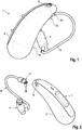
- a hearing device in the form of a hearing aid device in short: "hearing device 1" is shown schematically.
- the hearing aid 1 is one whose housing 2, which houses the electronics, is to be worn behind the ear (“BTE”) and which has an external loudspeaker 4.
- BTE behind the ear
- RIC receiveriver in canal
- the loudspeaker 4 is in the intended coupling state (see Sect. Fig. 1 ) by means of a loudspeaker connection cable ("cable 6" for short) with the housing 2, specifically with the electronics arranged therein - for example a signal processor.
- a connector receptacle for short: "socket 10" for receiving a connector 12 of the cable 6 is on a
- the surface 14 faces downward.
- the socket 10 is let into the above-mentioned surface 14, ie sunk.
- the socket 10 is countersunk in such a way that in the inserted state (see Fig. Fig. 1 ) the connector 12 does not protrude beyond the surface 14, or protrudes only negligibly.
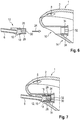
- the plug connector 12 is shown dismantled from the socket 10. It can be seen here that the plug connector 12 has a base body 16 which is injection-molded from a first, thermoplastic material. A circumferential seal 18 made of liquid silicone rubber is injection molded onto this base body 16. In addition, the base body 16 has a groove 20 as part of a retaining device. A bow-shaped wire spring 22 is inserted into the socket 10 as a further part of the retaining device, which is initially tensioned radially outward when the base body 16 is inserted and then "snaps" into the groove 20. As a result, the plug connector 12 can be held in the socket 10 without further locking elements being required.
- the plug connector 12 and the socket 10 are designed in such a way that the coupling takes place by means of a straight insertion movement along an insertion direction 24.
- the plug connector 12 has a plate 26 which is preferably encapsulated by the base body 16 and which carries a plurality, here three in each case, of contact elements 28 on an upper side and on a lower side.
- the contact elements 28 are arranged as flat elements in the surface of the plate 26.
- contact springs corresponding to the contact elements 28 are arranged in a manner not shown.
- Fig. 4 It can be seen that the connector 12 and the socket 10 have mutually complementary profiles, specifically asymmetrical ovals with a flattened (upper) side. This enables a clear alignment during assembly.
- the plug connector 12 serves to connect, for example, a permanently installed, rechargeable battery of the hearing aid 1 to an energy source.
- the plug connector 12 can also be used to couple a signal processor of the hearing aid 1 to a programming unit, specifically a computer on which the fitting software is implemented so that it can run.
Landscapes
- Engineering & Computer Science (AREA)
- Health & Medical Sciences (AREA)
- General Health & Medical Sciences (AREA)
- Neurosurgery (AREA)
- Otolaryngology (AREA)
- Physics & Mathematics (AREA)
- Acoustics & Sound (AREA)
- Signal Processing (AREA)
- Computer Networks & Wireless Communication (AREA)
- Details Of Connecting Devices For Male And Female Coupling (AREA)
- Headphones And Earphones (AREA)
Applications Claiming Priority (1)
| Application Number | Priority Date | Filing Date | Title |
|---|---|---|---|
| DE102020205439.8A DE102020205439A1 (de) | 2020-04-29 | 2020-04-29 | Hörvorrichtung |
Publications (3)
| Publication Number | Publication Date |
|---|---|
| EP3905723A1 true EP3905723A1 (fr) | 2021-11-03 |
| EP3905723B1 EP3905723B1 (fr) | 2024-10-23 |
| EP3905723C0 EP3905723C0 (fr) | 2024-10-23 |
Family
ID=75529903
Family Applications (1)
| Application Number | Title | Priority Date | Filing Date |
|---|---|---|---|
| EP21168412.1A Active EP3905723B1 (fr) | 2020-04-29 | 2021-04-14 | Dispositif auditif |
Country Status (4)
| Country | Link |
|---|---|
| US (1) | US11729558B2 (fr) |
| EP (1) | EP3905723B1 (fr) |
| CN (1) | CN113573223A (fr) |
| DE (1) | DE102020205439A1 (fr) |
Families Citing this family (2)
| Publication number | Priority date | Publication date | Assignee | Title |
|---|---|---|---|---|
| DE202022101121U1 (de) | 2022-03-01 | 2022-03-09 | Sonova Ag | Hinter-dem-Ohr-Teil für ein Hörgerät |
| CN223219182U (zh) * | 2024-04-11 | 2025-08-12 | 深圳市韶音听力科技有限公司 | 一种可穿戴设备 |
Citations (5)
| Publication number | Priority date | Publication date | Assignee | Title |
|---|---|---|---|---|
| US20120014549A1 (en) * | 2010-07-14 | 2012-01-19 | Starkey Laboratories, Inc. | Receiver-in-canal hearing device cable connections |
| EP2456235A1 (fr) * | 2010-11-17 | 2012-05-23 | Yamaichi Electronics Deutschland GmbH | Appareil auditif, connecteur, utilisation d'un connecteur et système de connexion d'un appareil auditif à un câble |
| DE102017128117A1 (de) * | 2017-11-28 | 2019-05-29 | Ear-Technic GmbH | Modulares Hörgerät |
| EP3503587A1 (fr) * | 2017-12-22 | 2019-06-26 | GN Hearing A/S | Connecteur d'une prothèse auditive |
| EP3537731A1 (fr) * | 2018-03-09 | 2019-09-11 | Oticon A/s | Unité de haut-parleur pour un système de prothèse auditive et système de prothèse auditive |
Family Cites Families (8)
| Publication number | Priority date | Publication date | Assignee | Title |
|---|---|---|---|---|
| DE3802250C1 (fr) | 1988-01-27 | 1988-10-27 | Sonar Design & Hoertechnik Gmbh, 4400 Muenster, De | |
| US7110562B1 (en) * | 2001-08-10 | 2006-09-19 | Hear-Wear Technologies, Llc | BTE/CIC auditory device and modular connector system therefor |
| JP5518214B2 (ja) * | 2010-02-11 | 2014-06-11 | シーメンス メディカル インストゥルメンツ ピーティーイー リミテッド | プラグインコネクタを有する耳掛け形補聴器 |
| DE202013000547U1 (de) | 2013-01-18 | 2013-02-25 | Siemens Medical Instruments Pte. Ltd. | Hörinstrumentgehäuse mit Steckverbindung |
| DE102013225429A1 (de) | 2013-12-10 | 2015-06-11 | Siemens Medical Instruments Pte. Ltd. | HdO-Hörinstrument mit Gehäuse und Traghaken |
| JP6408243B2 (ja) | 2014-04-23 | 2018-10-17 | 丸山 誠二 | 耳近接スピーカ装置 |
| US10887706B2 (en) * | 2015-06-29 | 2021-01-05 | Hear-Wear Technologies LLC | Transducer modules for auditory communication devices and auditory communication devices |
| EP3226582A1 (fr) * | 2016-03-29 | 2017-10-04 | Oticon Medical A/S | Dispositif auditif comprenant des moyens de prise modulaire |
-
2020
- 2020-04-29 DE DE102020205439.8A patent/DE102020205439A1/de active Pending
-
2021
- 2021-04-14 EP EP21168412.1A patent/EP3905723B1/fr active Active
- 2021-04-29 CN CN202110473257.9A patent/CN113573223A/zh active Pending
- 2021-04-29 US US17/243,846 patent/US11729558B2/en active Active
Patent Citations (5)
| Publication number | Priority date | Publication date | Assignee | Title |
|---|---|---|---|---|
| US20120014549A1 (en) * | 2010-07-14 | 2012-01-19 | Starkey Laboratories, Inc. | Receiver-in-canal hearing device cable connections |
| EP2456235A1 (fr) * | 2010-11-17 | 2012-05-23 | Yamaichi Electronics Deutschland GmbH | Appareil auditif, connecteur, utilisation d'un connecteur et système de connexion d'un appareil auditif à un câble |
| DE102017128117A1 (de) * | 2017-11-28 | 2019-05-29 | Ear-Technic GmbH | Modulares Hörgerät |
| EP3503587A1 (fr) * | 2017-12-22 | 2019-06-26 | GN Hearing A/S | Connecteur d'une prothèse auditive |
| EP3537731A1 (fr) * | 2018-03-09 | 2019-09-11 | Oticon A/s | Unité de haut-parleur pour un système de prothèse auditive et système de prothèse auditive |
Also Published As
| Publication number | Publication date |
|---|---|
| EP3905723B1 (fr) | 2024-10-23 |
| US20210345049A1 (en) | 2021-11-04 |
| US11729558B2 (en) | 2023-08-15 |
| DE102020205439A1 (de) | 2021-11-04 |
| CN113573223A (zh) | 2021-10-29 |
| EP3905723C0 (fr) | 2024-10-23 |
Similar Documents
| Publication | Publication Date | Title |
|---|---|---|
| EP2540098B1 (fr) | Connecteur pour appareil auditif ric-bte et appareil auditif ric-bte | |
| DE68918327T3 (de) | Programmierungsschnittstelle für Hörgeräte. | |
| EP2285136B1 (fr) | Aide auditive dotée d'un écouteur échangeable | |
| DE102010002176A1 (de) | Kontakteinrichtung | |
| EP3905723B1 (fr) | Dispositif auditif | |
| DE102007008551A1 (de) | Hörvorrichtung mit magnetisch befestigtem Batteriefach | |
| EP1993323B1 (fr) | Pièce d'oreille pour un dispositif auditif doté d'une fermeture à baïonnette | |
| EP3196684A1 (fr) | Connecteur | |
| EP2040488A2 (fr) | Outil destiné à l'introduction d'un écouteur d'un dispositif auditif dans un conduit auditif | |
| DE2751755C2 (de) | Leitungsverbinder für ein Hörgerät | |
| EP2456235B1 (fr) | Appareil auditif, connecteur, utilisation d'un connecteur et système de connexion d'un appareil auditif à un câble | |
| DE102010040930B4 (de) | Hörgerät mit einer Batterielade | |
| DE3207256A1 (de) | Hoerhilfegeraet | |
| DE102012101609A1 (de) | Montagemodul für die Wandmontage eines Anzeigeelementes | |
| DE102008008670A1 (de) | Ladegerät für eine Hörvorrichtung mit einem bewegbaren Ladekontakt | |
| DE102008024515B3 (de) | Hörhilfe und Anordnung | |
| WO2015036305A1 (fr) | Connecteur enfichable | |
| EP0244671A1 (fr) | Méthode et dispositif pour la réalisation d'une mesure acoustique de comparaison | |
| DE102012016154A1 (de) | Türspiegel | |
| DE102005009377B3 (de) | Im-Ohr-Hörgerät mit abnehmbarem Lautsprecher | |
| EP0334837A3 (fr) | Prothèse auditive avec prise d'entrée audio | |
| CH668154A5 (en) | Hearing aid with electroacoustic transducer - fits behind ear and has facility for plugging in range of operational mode elements | |
| EP3419312B1 (fr) | Appareil auditif | |
| DE102021205471B3 (de) | Hörvorrichtung | |
| EP2018078A2 (fr) | Dispositif auditif doté d'un dispositif de fixation destiné à atteler un manchon audio et manchon audio correspondant |
Legal Events
| Date | Code | Title | Description |
|---|---|---|---|
| PUAI | Public reference made under article 153(3) epc to a published international application that has entered the european phase |
Free format text: ORIGINAL CODE: 0009012 |
|
| STAA | Information on the status of an ep patent application or granted ep patent |
Free format text: STATUS: THE APPLICATION HAS BEEN PUBLISHED |
|
| AK | Designated contracting states |
Kind code of ref document: A1 Designated state(s): AL AT BE BG CH CY CZ DE DK EE ES FI FR GB GR HR HU IE IS IT LI LT LU LV MC MK MT NL NO PL PT RO RS SE SI SK SM TR |
|
| B565 | Issuance of search results under rule 164(2) epc |
Effective date: 20210922 |
|
| STAA | Information on the status of an ep patent application or granted ep patent |
Free format text: STATUS: REQUEST FOR EXAMINATION WAS MADE |
|
| 17P | Request for examination filed |
Effective date: 20220218 |
|
| RBV | Designated contracting states (corrected) |
Designated state(s): AL AT BE BG CH CY CZ DE DK EE ES FI FR GB GR HR HU IE IS IT LI LT LU LV MC MK MT NL NO PL PT RO RS SE SI SK SM TR |
|
| STAA | Information on the status of an ep patent application or granted ep patent |
Free format text: STATUS: EXAMINATION IS IN PROGRESS |
|
| RIN1 | Information on inventor provided before grant (corrected) |
Inventor name: KRAL, HOLGER Inventor name: DING, LIT SONG GLEN Inventor name: ANG, THAI WEE Inventor name: BIN SHITH, MUHAMMAD SHAHID |
|
| 17Q | First examination report despatched |
Effective date: 20220804 |
|
| GRAP | Despatch of communication of intention to grant a patent |
Free format text: ORIGINAL CODE: EPIDOSNIGR1 |
|
| STAA | Information on the status of an ep patent application or granted ep patent |
Free format text: STATUS: GRANT OF PATENT IS INTENDED |
|
| INTG | Intention to grant announced |
Effective date: 20240627 |
|
| GRAS | Grant fee paid |
Free format text: ORIGINAL CODE: EPIDOSNIGR3 |
|
| GRAA | (expected) grant |
Free format text: ORIGINAL CODE: 0009210 |
|
| STAA | Information on the status of an ep patent application or granted ep patent |
Free format text: STATUS: THE PATENT HAS BEEN GRANTED |
|
| AK | Designated contracting states |
Kind code of ref document: B1 Designated state(s): AL AT BE BG CH CY CZ DE DK EE ES FI FR GB GR HR HU IE IS IT LI LT LU LV MC MK MT NL NO PL PT RO RS SE SI SK SM TR |
|
| REG | Reference to a national code |
Ref country code: GB Ref legal event code: FG4D Free format text: NOT ENGLISH |
|
| REG | Reference to a national code |
Ref country code: CH Ref legal event code: EP |
|
| REG | Reference to a national code |
Ref country code: DE Ref legal event code: R096 Ref document number: 502021005543 Country of ref document: DE |
|
| REG | Reference to a national code |
Ref country code: IE Ref legal event code: FG4D Free format text: LANGUAGE OF EP DOCUMENT: GERMAN |
|
| U01 | Request for unitary effect filed |
Effective date: 20241023 |
|
| U07 | Unitary effect registered |
Designated state(s): AT BE BG DE DK EE FI FR IT LT LU LV MT NL PT RO SE SI Effective date: 20241107 |
|
| PG25 | Lapsed in a contracting state [announced via postgrant information from national office to epo] |
Ref country code: IS Free format text: LAPSE BECAUSE OF FAILURE TO SUBMIT A TRANSLATION OF THE DESCRIPTION OR TO PAY THE FEE WITHIN THE PRESCRIBED TIME-LIMIT Effective date: 20250223 Ref country code: HR Free format text: LAPSE BECAUSE OF FAILURE TO SUBMIT A TRANSLATION OF THE DESCRIPTION OR TO PAY THE FEE WITHIN THE PRESCRIBED TIME-LIMIT Effective date: 20241023 |
|
| PG25 | Lapsed in a contracting state [announced via postgrant information from national office to epo] |
Ref country code: ES Free format text: LAPSE BECAUSE OF FAILURE TO SUBMIT A TRANSLATION OF THE DESCRIPTION OR TO PAY THE FEE WITHIN THE PRESCRIBED TIME-LIMIT Effective date: 20241023 |
|
| PG25 | Lapsed in a contracting state [announced via postgrant information from national office to epo] |
Ref country code: NO Free format text: LAPSE BECAUSE OF FAILURE TO SUBMIT A TRANSLATION OF THE DESCRIPTION OR TO PAY THE FEE WITHIN THE PRESCRIBED TIME-LIMIT Effective date: 20250123 |
|
| U20 | Renewal fee for the european patent with unitary effect paid |
Year of fee payment: 5 Effective date: 20250319 |
|
| PG25 | Lapsed in a contracting state [announced via postgrant information from national office to epo] |
Ref country code: GR Free format text: LAPSE BECAUSE OF FAILURE TO SUBMIT A TRANSLATION OF THE DESCRIPTION OR TO PAY THE FEE WITHIN THE PRESCRIBED TIME-LIMIT Effective date: 20250124 |
|
| PG25 | Lapsed in a contracting state [announced via postgrant information from national office to epo] |
Ref country code: PL Free format text: LAPSE BECAUSE OF FAILURE TO SUBMIT A TRANSLATION OF THE DESCRIPTION OR TO PAY THE FEE WITHIN THE PRESCRIBED TIME-LIMIT Effective date: 20241023 |
|
| PG25 | Lapsed in a contracting state [announced via postgrant information from national office to epo] |
Ref country code: RS Free format text: LAPSE BECAUSE OF FAILURE TO SUBMIT A TRANSLATION OF THE DESCRIPTION OR TO PAY THE FEE WITHIN THE PRESCRIBED TIME-LIMIT Effective date: 20250123 |
|
| PG25 | Lapsed in a contracting state [announced via postgrant information from national office to epo] |
Ref country code: SM Free format text: LAPSE BECAUSE OF FAILURE TO SUBMIT A TRANSLATION OF THE DESCRIPTION OR TO PAY THE FEE WITHIN THE PRESCRIBED TIME-LIMIT Effective date: 20241023 |
|
| PGFP | Annual fee paid to national office [announced via postgrant information from national office to epo] |
Ref country code: CH Payment date: 20250501 Year of fee payment: 5 |
|
| PG25 | Lapsed in a contracting state [announced via postgrant information from national office to epo] |
Ref country code: SK Free format text: LAPSE BECAUSE OF FAILURE TO SUBMIT A TRANSLATION OF THE DESCRIPTION OR TO PAY THE FEE WITHIN THE PRESCRIBED TIME-LIMIT Effective date: 20241023 |
|
| PG25 | Lapsed in a contracting state [announced via postgrant information from national office to epo] |
Ref country code: CZ Free format text: LAPSE BECAUSE OF FAILURE TO SUBMIT A TRANSLATION OF THE DESCRIPTION OR TO PAY THE FEE WITHIN THE PRESCRIBED TIME-LIMIT Effective date: 20241023 |
|
| PLBE | No opposition filed within time limit |
Free format text: ORIGINAL CODE: 0009261 |
|
| STAA | Information on the status of an ep patent application or granted ep patent |
Free format text: STATUS: NO OPPOSITION FILED WITHIN TIME LIMIT |
|
| 26N | No opposition filed |
Effective date: 20250724 |
|
| PG25 | Lapsed in a contracting state [announced via postgrant information from national office to epo] |
Ref country code: MC Free format text: LAPSE BECAUSE OF FAILURE TO SUBMIT A TRANSLATION OF THE DESCRIPTION OR TO PAY THE FEE WITHIN THE PRESCRIBED TIME-LIMIT Effective date: 20241023 |
|
| PGFP | Annual fee paid to national office [announced via postgrant information from national office to epo] |
Ref country code: GB Payment date: 20260319 Year of fee payment: 6 |
|
| PG25 | Lapsed in a contracting state [announced via postgrant information from national office to epo] |
Ref country code: IE Free format text: LAPSE BECAUSE OF NON-PAYMENT OF DUE FEES Effective date: 20250414 |
|
| U20 | Renewal fee for the european patent with unitary effect paid |
Year of fee payment: 6 Effective date: 20260319 |