EP3905723A1 - Hearing device - Google Patents
Hearing device Download PDFInfo
- Publication number
- EP3905723A1 EP3905723A1 EP21168412.1A EP21168412A EP3905723A1 EP 3905723 A1 EP3905723 A1 EP 3905723A1 EP 21168412 A EP21168412 A EP 21168412A EP 3905723 A1 EP3905723 A1 EP 3905723A1
- Authority
- EP
- European Patent Office
- Prior art keywords
- connector
- hearing device
- loudspeaker
- housing
- intended
- Prior art date
- Legal status (The legal status is an assumption and is not a legal conclusion. Google has not performed a legal analysis and makes no representation as to the accuracy of the status listed.)
- Granted
Links
Images


Classifications
-
- H—ELECTRICITY
- H04—ELECTRIC COMMUNICATION TECHNIQUE
- H04R—LOUDSPEAKERS, MICROPHONES, GRAMOPHONE PICK-UPS OR LIKE ACOUSTIC ELECTROMECHANICAL TRANSDUCERS; ELECTRIC HEARING AIDS; PUBLIC ADDRESS SYSTEMS
- H04R25/00—Electric hearing aids
- H04R25/55—Electric hearing aids using an external connection, either wireless or wired
- H04R25/556—External connectors, e.g. plugs or modules
-
- H—ELECTRICITY
- H01—ELECTRIC ELEMENTS
- H01R—ELECTRICALLY-CONDUCTIVE CONNECTIONS; STRUCTURAL ASSOCIATIONS OF A PLURALITY OF MUTUALLY-INSULATED ELECTRICAL CONNECTING ELEMENTS; COUPLING DEVICES; CURRENT COLLECTORS
- H01R13/00—Details of coupling devices of the kinds covered by groups H01R12/70 or H01R24/00 - H01R33/00
- H01R13/46—Bases; Cases
- H01R13/52—Dustproof, splashproof, drip-proof, waterproof, or flameproof cases
- H01R13/5219—Sealing means between coupling parts, e.g. interfacial seal
-
- H—ELECTRICITY
- H01—ELECTRIC ELEMENTS
- H01R—ELECTRICALLY-CONDUCTIVE CONNECTIONS; STRUCTURAL ASSOCIATIONS OF A PLURALITY OF MUTUALLY-INSULATED ELECTRICAL CONNECTING ELEMENTS; COUPLING DEVICES; CURRENT COLLECTORS
- H01R13/00—Details of coupling devices of the kinds covered by groups H01R12/70 or H01R24/00 - H01R33/00
- H01R13/62—Means for facilitating engagement or disengagement of coupling parts or for holding them in engagement
- H01R13/629—Additional means for facilitating engagement or disengagement of coupling parts, e.g. aligning or guiding means, levers, gas pressure electrical locking indicators, manufacturing tolerances
- H01R13/631—Additional means for facilitating engagement or disengagement of coupling parts, e.g. aligning or guiding means, levers, gas pressure electrical locking indicators, manufacturing tolerances for engagement only
-
- H—ELECTRICITY
- H04—ELECTRIC COMMUNICATION TECHNIQUE
- H04R—LOUDSPEAKERS, MICROPHONES, GRAMOPHONE PICK-UPS OR LIKE ACOUSTIC ELECTROMECHANICAL TRANSDUCERS; ELECTRIC HEARING AIDS; PUBLIC ADDRESS SYSTEMS
- H04R25/00—Electric hearing aids
- H04R25/60—Mounting or interconnection of hearing aid parts, e.g. inside tips, housings or to ossicles
- H04R25/602—Mounting or interconnection of hearing aid parts, e.g. inside tips, housings or to ossicles of batteries
-
- H—ELECTRICITY
- H04—ELECTRIC COMMUNICATION TECHNIQUE
- H04R—LOUDSPEAKERS, MICROPHONES, GRAMOPHONE PICK-UPS OR LIKE ACOUSTIC ELECTROMECHANICAL TRANSDUCERS; ELECTRIC HEARING AIDS; PUBLIC ADDRESS SYSTEMS
- H04R25/00—Electric hearing aids
- H04R25/60—Mounting or interconnection of hearing aid parts, e.g. inside tips, housings or to ossicles
- H04R25/604—Mounting or interconnection of hearing aid parts, e.g. inside tips, housings or to ossicles of acoustic or vibrational transducers
-
- H—ELECTRICITY
- H04—ELECTRIC COMMUNICATION TECHNIQUE
- H04R—LOUDSPEAKERS, MICROPHONES, GRAMOPHONE PICK-UPS OR LIKE ACOUSTIC ELECTROMECHANICAL TRANSDUCERS; ELECTRIC HEARING AIDS; PUBLIC ADDRESS SYSTEMS
- H04R25/00—Electric hearing aids
- H04R25/60—Mounting or interconnection of hearing aid parts, e.g. inside tips, housings or to ossicles
- H04R25/607—Mounting or interconnection of hearing aid parts, e.g. inside tips, housings or to ossicles of earhooks
-
- H—ELECTRICITY
- H04—ELECTRIC COMMUNICATION TECHNIQUE
- H04R—LOUDSPEAKERS, MICROPHONES, GRAMOPHONE PICK-UPS OR LIKE ACOUSTIC ELECTROMECHANICAL TRANSDUCERS; ELECTRIC HEARING AIDS; PUBLIC ADDRESS SYSTEMS
- H04R2225/00—Details of deaf aids covered by H04R25/00, not provided for in any of its subgroups
- H04R2225/021—Behind the ear [BTE] hearing aids
Definitions
- the invention relates to a hearing device, in particular a hearing aid device.
- Hearing devices are usually used to output a sound signal to the hearing of the wearer of this hearing device.
- the output takes place by means of an output transducer, usually in an acoustic way via airborne sound by means of a loudspeaker (also referred to as “listener” or “receiver”).
- Such hearing devices are often used as so-called hearing aid devices (also known as hearing aids for short).
- the hearing devices usually include an acoustic input transducer (in particular a microphone) and a signal processor which is set up to process the input signal (also: microphone signal) generated by the input transducer from the ambient sound using at least one usually user-specifically stored signal processing algorithm in such a way that a Hearing loss of the wearer of the hearing device is at least partially compensated for.
- the output transducer can also be a so-called bone conduction receiver or a cochlear implant, in addition to a loudspeaker, which are set up for mechanical or electrical coupling of the audio signal into the wearer's hearing.
- hearing devices also includes, in particular, devices such as so-called tinnitus maskers, headsets, headphones and the like.
- Hearing devices in particular hearing aids, are regularly used in the form of devices to be worn behind the ear (also: “BTE") or in the ear (also: “ITE”).
- BTEs can in turn be differentiated into devices that have the loudspeaker in the BTE housing and devices that who have to wear the loudspeaker externally, in particular as intended in the ear canal.
- the latter are often referred to as "RIC"("receiver in channel”) hearing aids.
- a connection cable is required between the electrical components arranged in the BTE housing (e.g. the respective microphone, preferably a signal processor which contains the aforementioned signal processing algorithm) and the loudspeaker.
- This connecting cable is usually coupled to the BTE housing in the region of the "tip" of the BTE housing, which is usually roughly banana-shaped.
- a corresponding connector is often designed in such a way that when the hearing aid is worn for the intended purpose, forward-facing microphones are not covered.
- a connection between the connecting cable and the BTE housing that is as secure as possible, ie stable and permanent against unintentional loosening, is also required.
- the invention is based on the object of specifying an improved connection between an external loudspeaker and a housing of a hearing device.
- the hearing device has a housing which is stretched along a longitudinal axis, has an oval cross-section and is designed to house electrical components of the hearing device. Furthermore, the hearing apparatus has a loudspeaker which, when the hearing apparatus is worn as intended, is arranged outside the housing and connected to at least some of the electrical components. In addition, the hearing apparatus has a connector which is connected to the loudspeaker, in particular by means of a loudspeaker connection cable, and which carries at least six contact elements for interconnecting the loudspeaker with the corresponding electrical components. Furthermore, the hearing device has a Connector receptacle for receiving the connector and interconnection of the respective contact elements.
- This plug connector receptacle is arranged in a surface of the housing that is directed towards the underside of the housing when it is worn as intended.
- the connector and the connector receptacle are also designed in such a way that an insertion direction in the intended wearing state runs from a front side to a rear side.
- the electrical components are preferably at least one microphone and a signal processor for processing signals output by the respective microphone.
- the hearing device also comprises a preferably rechargeable battery unit, also referred to as a battery pack, as a (in particular further) electrical component.
- the battery unit in turn preferably comprises charging electronics for controlling and monitoring a discharging or charging process.
- the microphone or at least one of several with a correspondingly assigned microphone opening can be moved as far as possible to the “tip” of the housing, which points forward when worn as intended.
- the housing which is oval in cross section, is preferably approximately rectangular with comparatively strongly rounded corners.
- the hearing device preferably forms a hearing aid, also referred to as a “hearing aid” for short.
- the hearing device thus forms a RIC hearing aid or also RIC BTE, since the housing described above is preferably to be worn behind the ear as intended.
- the external loudspeaker on the other hand, is to be worn in the ear, preferably in the ear canal, when it is worn as intended.
- the plug connector receptacle is sunk into the surface of the housing facing the underside, preferably in such a way that the plug connector in the intended plugged-in state of a Side direction is hidden from a view.
- the connector is on the one hand “invisible” when it is worn as intended, but on the other hand a contact surface that is as flat as possible is advantageously formed on the ear of the user.
- the connector and the connector receptacle are designed to be complementary to one another and to be self-aligning.
- both have an asymmetrical, preferably partially flattened, oval profile.
- the connector and the connector receptacle each have a part of a retaining device that can be automatically actuated in the insertion direction.
- a retaining device that can be automatically actuated in the insertion direction.
- the connector as part of the retaining device, has a groove and the connector receptacle has a wire spring (which is preferably designed in the manner of a C-ring).
- This wire spring engages in the groove in the intended coupling state, so that a reversibly effective form fit is formed against unintentional removal of the connector.
- the connector has an injection-molded base body made from a first plastic.
- a circumferential seal made of a second plastic is molded onto this base body and is preferably connected to it in a materially bonded manner.
- the seal can be molded in a multi-component injection molding process.
- the seal is preferably formed by what is known as “liquid injection molding” with the introduction of, in particular, a liquid silicone rubber (also: “liquid silicone rubber”, “LSR” for short). This allows manual positioning of the seal during the Assembly, which is often difficult and expensive due to the comparatively small dimensions of hearing aids (and thus also of the connector), is not necessary.
- the plug connector has an injection-molded base body (in particular the one described above).
- this base body In the intended coupling state, this base body is arranged at an angle to the surface of the housing facing the underside. Therefore, an end face of the base body facing the loudspeaker, from which the loudspeaker connecting cable emerges, is positioned following the surface of the housing facing the underside at an angle with respect to a cable exit direction of the loudspeaker connecting cable.
- this end face of the connector is oriented obliquely so that the end face in the intended coupling state is arranged essentially (i.e. with slight deviations) parallel to the downwardly directed surface and preferably also lying in its plane.
- the connector in particular its base body, is preferably only slightly larger in cross section than the loudspeaker connection cable, for example up to a factor of two.
- the plug connector has a contact carrier in the form of a plate protruding from the end face facing away from the loudspeaker (in particular of the base body).
- the contact elements described above are designed as contact surfaces and, in particular, are arranged distributed on both sides. This plate represents a comparatively stable means of contacting and its basic principle is similar to a contact carrier of a USB 2.0 type A connector.
- the plug connector receptacle has corresponding spring contacts for contacting each of the contact surfaces described above.
- the plug connector has a coding, in particular a color coding, for displaying the side assigned to the corresponding ear of a user.
- a coding in particular a color coding
- the plug connector has a coding, in particular a color coding, for displaying the side assigned to the corresponding ear of a user.
- the connector for the right ear is in a first color, e.g. B. blue, and the one for the left ear in a second color, for example red, colored.
- the connector receptacle is in particular colored accordingly so that a clear assignment is possible.
- At least the connector receptacle has contact elements which are set up and provided (preferably in addition to the above-described interconnection of the loudspeaker) for charging the rechargeable battery unit and / or for exchanging data with the signal processor.
- the signal processor is regularly set up to execute at least one signal processing algorithm for processing the (microphone) signals.
- This (or the respective) signal processing algorithm can advantageously be parameterized in a user-specific manner, which in the present embodiment can expediently also take place via the plug connector receptacle while saving an additional interface.
- the loudspeaker and the associated cable are preferably removed for parameterization and a data cable with a comparable connector is connected to the connector receptacle.
- a hearing device in the form of a hearing aid device in short: "hearing device 1" is shown schematically.
- the hearing aid 1 is one whose housing 2, which houses the electronics, is to be worn behind the ear (“BTE”) and which has an external loudspeaker 4.
- BTE behind the ear
- RIC receiveriver in canal
- the loudspeaker 4 is in the intended coupling state (see Sect. Fig. 1 ) by means of a loudspeaker connection cable ("cable 6" for short) with the housing 2, specifically with the electronics arranged therein - for example a signal processor.
- a connector receptacle for short: "socket 10" for receiving a connector 12 of the cable 6 is on a
- the surface 14 faces downward.
- the socket 10 is let into the above-mentioned surface 14, ie sunk.
- the socket 10 is countersunk in such a way that in the inserted state (see Fig. Fig. 1 ) the connector 12 does not protrude beyond the surface 14, or protrudes only negligibly.
- the plug connector 12 is shown dismantled from the socket 10. It can be seen here that the plug connector 12 has a base body 16 which is injection-molded from a first, thermoplastic material. A circumferential seal 18 made of liquid silicone rubber is injection molded onto this base body 16. In addition, the base body 16 has a groove 20 as part of a retaining device. A bow-shaped wire spring 22 is inserted into the socket 10 as a further part of the retaining device, which is initially tensioned radially outward when the base body 16 is inserted and then "snaps" into the groove 20. As a result, the plug connector 12 can be held in the socket 10 without further locking elements being required.
- the plug connector 12 and the socket 10 are designed in such a way that the coupling takes place by means of a straight insertion movement along an insertion direction 24.
- the plug connector 12 has a plate 26 which is preferably encapsulated by the base body 16 and which carries a plurality, here three in each case, of contact elements 28 on an upper side and on a lower side.
- the contact elements 28 are arranged as flat elements in the surface of the plate 26.
- contact springs corresponding to the contact elements 28 are arranged in a manner not shown.
- Fig. 4 It can be seen that the connector 12 and the socket 10 have mutually complementary profiles, specifically asymmetrical ovals with a flattened (upper) side. This enables a clear alignment during assembly.
- the plug connector 12 serves to connect, for example, a permanently installed, rechargeable battery of the hearing aid 1 to an energy source.
- the plug connector 12 can also be used to couple a signal processor of the hearing aid 1 to a programming unit, specifically a computer on which the fitting software is implemented so that it can run.
Landscapes
- Engineering & Computer Science (AREA)
- Health & Medical Sciences (AREA)
- General Health & Medical Sciences (AREA)
- Neurosurgery (AREA)
- Otolaryngology (AREA)
- Physics & Mathematics (AREA)
- Acoustics & Sound (AREA)
- Signal Processing (AREA)
- Computer Networks & Wireless Communication (AREA)
- Details Of Connecting Devices For Male And Female Coupling (AREA)
- Headphones And Earphones (AREA)
Abstract
Eine erfindungsgemäße Hörvorrichtung (1) weist ein Gehäuse (2) auf, das entlang einer Längsachse gestreckt, im Querschnitt oval ausgebildet und zur Einhausung von elektrischen Komponenten der Hörvorrichtung (1) eingerichtet ist, einen im bestimmungsgemäßen Tragezustand der Hörvorrichtung (1) außerhalb des Gehäuses (2) angeordneten und mit zumindest einem Teil der elektrischen Komponenten verschalteten Lautsprecher (4), und einen mit dem Lautsprecher (4) verbundenen Steckverbinder (12), der wenigstens sechs Kontaktelemente (28) zur Verschaltung des Lautsprechers (4) mit den entsprechenden elektrischen Komponenten trägt. Des Weiteren weist die Hörvorrichtung (1) eine Steckverbinder-Aufnahme (10) zur Aufnahme des Steckverbinders (12) und Verschaltung der jeweiligen Kontaktelemente (28) auf, wobei die Steckverbinder-Aufnahme (10) in einer im bestimmungsgemäßen Tragezustand zur Unterseite gerichteten Fläche (14) des Gehäuses (2) angeordnet ist. Außerdem sind der Steckverbinder (12) und die Steckverbinder-Aufnahme (10) derart ausgebildet, dass eine Einsteckrichtung (24) im bestimmungsgemäßen Tragezustand von einer Frontseite zu einer Rückseite verläuft.
Description
Die Erfindung betrifft eine Hörvorrichtung, insbesondere ein Hörhilfegerät.The invention relates to a hearing device, in particular a hearing aid device.
Hörvorrichtungen dienen üblicherweise zur Ausgabe eines Tonsignals an das Gehör des Trägers dieser Hörvorrichtung. Die Ausgabe erfolgt dabei mittels eines Ausgabewandlers, meist auf akustischem Weg über Luftschall mittels eines Lautsprechers (auch als "Hörer" oder "Receiver" bezeichnet). Häufig kommen derartige Hörvorrichtungen dabei als sogenannte Hörhilfegeräte (auch kurz: Hörgeräte) zum Einsatz. Dazu umfassen die Hörvorrichtungen normalerweise einen akustischen Eingangswandler (insbesondere ein Mikrophon) und einen Signalprozessor, der dazu eingerichtet ist, das von dem Eingangswandler aus dem Umgebungsschall erzeugte Eingangssignal (auch: Mikrophonsignal) unter Anwendung mindestens eines üblicherweise nutzerspezifisch hinterlegten Signalverarbeitungsalgorithmus derart zu verarbeiten, dass eine Hörminderung des Trägers der Hörvorrichtung zumindest teilweise kompensiert wird. Insbesondere im Fall eines Hörhilfegeräts kann es sich bei dem Ausgabewandler neben einem Lautsprecher auch alternativ um einen sogenannten Knochenleitungshörer oder ein Cochlea-Implantat handeln, die zur mechanischen oder elektrischen Einkopplung des Tonsignals in das Gehör des Trägers eingerichtet sind. Unter dem Begriff Hörvorrichtungen fallen zusätzlich insbesondere auch Geräte wie z.B. sogenannte Tinnitus-Masker, Headsets, Kopfhörer und dergleichen.Hearing devices are usually used to output a sound signal to the hearing of the wearer of this hearing device. The output takes place by means of an output transducer, usually in an acoustic way via airborne sound by means of a loudspeaker (also referred to as "listener" or "receiver"). Such hearing devices are often used as so-called hearing aid devices (also known as hearing aids for short). For this purpose, the hearing devices usually include an acoustic input transducer (in particular a microphone) and a signal processor which is set up to process the input signal (also: microphone signal) generated by the input transducer from the ambient sound using at least one usually user-specifically stored signal processing algorithm in such a way that a Hearing loss of the wearer of the hearing device is at least partially compensated for. In particular in the case of a hearing aid device, the output transducer can also be a so-called bone conduction receiver or a cochlear implant, in addition to a loudspeaker, which are set up for mechanical or electrical coupling of the audio signal into the wearer's hearing. The term hearing devices also includes, in particular, devices such as so-called tinnitus maskers, headsets, headphones and the like.
Hörvorrichtungen, insbesondere Hörgeräte kommen dabei regelmäßig in Form von hinter dem Ohr (auch: "HdO") oder in dem Ohr (auch: "IdO") zu tragenden Geräten zum Einsatz. HdOs können dabei wiederum unterschieden werden in Geräte, die den Lautsprecher in dem HdO-Gehäuse aufweisen, sowie in solche Geräte, die den Lautsprecher extern, insbesondere bestimmungsgemäß im Gehörgang zu tragen haben. Letztere werden häufig auch als "RIC"- ("receiver in canal") Hörgeräte bezeichnet. Dabei ist erkanntermaßen ein Verbindungskabel zwischen den im HdO-Gehäuse angeordneten elektrischen Komponenten (z. B. dem jeweiligen Mikrofon, bevorzugt einem Signalprozessor, der den vorstehend genannten Signalverarbeitungsalgorithmus enthält) und dem Lautsprecher erforderlich. Meist ist dieses Verbindungskabel im Bereich der "Spitze" des regelmäßig grob bananenförmig ausgebildeten HdO-Gehäuses mit letzterem gekoppelt. Ein entsprechender Konnektor ist dabei oft derart gestaltet, dass im bestimmungsgemäßen Tragezustand des Hörgeräts nach vorne gerichtete Mikrofone nicht verdeckt sind. Zudem ist aber auch eine möglichst verliersichere, d. h. stabile und gegen unbeabsichtigtes Lösen dauerhafte, Verbindung zwischen dem Verbindungskabel und dem HdO-Gehäuse erforderlich.Hearing devices, in particular hearing aids, are regularly used in the form of devices to be worn behind the ear (also: "BTE") or in the ear (also: "ITE"). BTEs can in turn be differentiated into devices that have the loudspeaker in the BTE housing and devices that who have to wear the loudspeaker externally, in particular as intended in the ear canal. The latter are often referred to as "RIC"("receiver in channel") hearing aids. It is recognized that a connection cable is required between the electrical components arranged in the BTE housing (e.g. the respective microphone, preferably a signal processor which contains the aforementioned signal processing algorithm) and the loudspeaker. This connecting cable is usually coupled to the BTE housing in the region of the "tip" of the BTE housing, which is usually roughly banana-shaped. A corresponding connector is often designed in such a way that when the hearing aid is worn for the intended purpose, forward-facing microphones are not covered. In addition, however, a connection between the connecting cable and the BTE housing that is as secure as possible, ie stable and permanent against unintentional loosening, is also required.
Der Erfindung liegt die Aufgabe zugrunde, eine verbesserte Verbindung zwischen einem externen Lautsprecher und einem Gehäuse einer Hörvorrichtung anzugeben.The invention is based on the object of specifying an improved connection between an external loudspeaker and a housing of a hearing device.
Diese Aufgabe wird erfindungsgemäß gelöst durch eine Hörvorrichtung mit den Merkmalen des Anspruchs 1. Vorteilhafte und teils für sich erfinderische Ausführungsformen und Weiterentwicklungen der Erfindung sind in den Unteransprüchen und der nachfolgenden Beschreibung dargelegt.This object is achieved according to the invention by a hearing device having the features of
Die erfindungsgemäße Hörvorrichtung weist ein Gehäuse auf, das entlang einer Längsachse gestreckt, im Querschnitt oval ausgebildet und zur Einhausung von elektrischen Komponenten der Hörvorrichtung eingerichtet ist. Des Weiteren weist die Hörvorrichtung einen Lautsprecher auf, der im bestimmungsgemäßen Tragezustand der Hörvorrichtung außerhalb des Gehäuses angeordneten und mit zumindest einem Teil der elektrischen Komponenten verschaltet ist. Außerdem weist die Hörvorrichtung einen mit dem Lautsprecher, insbesondere mittels eines Lautsprecherverbindungskabels, verbundenen Steckverbinder auf, der wenigstens sechs Kontaktelemente zur Verschaltung des Lautsprechers mit den entsprechenden elektrischen Komponenten trägt. Weiterhin weist die Hörvorrichtung eine Steckverbinder-Aufnahme zur Aufnahme des Steckverbinders und Verschaltung der jeweiligen Kontaktelemente auf. Diese Steckverbinder-Aufnahme ist dabei in einer im bestimmungsgemäßen Tragezustand zur Unterseite gerichteten Fläche des Gehäuses angeordnet. Der Steckverbinder und die Steckverbinder-Aufnahme sind außerdem derart ausgebildet, dass eine Einsteckrichtung im bestimmungsgemäßen Tragezustand von einer Frontseite zu einer Rückseite verläuft.The hearing device according to the invention has a housing which is stretched along a longitudinal axis, has an oval cross-section and is designed to house electrical components of the hearing device. Furthermore, the hearing apparatus has a loudspeaker which, when the hearing apparatus is worn as intended, is arranged outside the housing and connected to at least some of the electrical components. In addition, the hearing apparatus has a connector which is connected to the loudspeaker, in particular by means of a loudspeaker connection cable, and which carries at least six contact elements for interconnecting the loudspeaker with the corresponding electrical components. Furthermore, the hearing device has a Connector receptacle for receiving the connector and interconnection of the respective contact elements. This plug connector receptacle is arranged in a surface of the housing that is directed towards the underside of the housing when it is worn as intended. The connector and the connector receptacle are also designed in such a way that an insertion direction in the intended wearing state runs from a front side to a rear side.
Bei den elektrischen Komponenten handelt es sich vorzugsweise um wenigstens ein Mikrofon und um einen Signalprozessor zur Verarbeitung von seitens des jeweiligen Mikrofons ausgegebenen Signalen. Optional umfasst die Hörvorrichtung als (insbesondere weitere) elektrische Komponente auch eine vorzugsweise wiederaufladbare Batterieeinheit, auch als Batteriepack bezeichnet. Die Batterieeinheit umfasst dabei vorzugsweise wiederum eine Ladeelektronik zur Steuerung und Überwachung eines Entlade- oder Ladevorgangs.The electrical components are preferably at least one microphone and a signal processor for processing signals output by the respective microphone. Optionally, the hearing device also comprises a preferably rechargeable battery unit, also referred to as a battery pack, as a (in particular further) electrical component. The battery unit in turn preferably comprises charging electronics for controlling and monitoring a discharging or charging process.
Da die Steckverbinder-Aufnahme in der "Unterseite" des Gehäuses angeordnet ist, kann das Mikrofon oder wenigstens eines von mehreren mit einer entsprechend zugeordneten Mikrofonöffnung möglichst weit zur im bestimmungsgemäßen Tragezustand nach vorne weisenden "Spitze" des Gehäuses versetzt werden.Since the connector receptacle is arranged in the "underside" of the housing, the microphone or at least one of several with a correspondingly assigned microphone opening can be moved as far as possible to the “tip” of the housing, which points forward when worn as intended.
Vorzugsweise ist das im Querschnitt ovale Gehäuse etwa rechteckförmig mit vergleichsweise stark abgerundeten Ecken ausgebildet.The housing, which is oval in cross section, is preferably approximately rectangular with comparatively strongly rounded corners.
Vorzugsweise bildet die Hörvorrichtung ein Hörhilfegerät, kurz auch als "Hörgerät" bezeichnet. Insbesondere bildet die Hörvorrichtung also ein RIC-Hörgerät oder auch RIC-HdO, da das vorstehend beschriebene Gehäuse bevorzugt bestimmungsgemäß hinter dem Ohr zu tragen ist. Der externe Lautsprecher ist dagegen im bestimmungsgemäßen Tragezustand im Ohr, vorzugsweise im Gehörgang zu tragen.The hearing device preferably forms a hearing aid, also referred to as a “hearing aid” for short. In particular, the hearing device thus forms a RIC hearing aid or also RIC BTE, since the housing described above is preferably to be worn behind the ear as intended. The external loudspeaker, on the other hand, is to be worn in the ear, preferably in the ear canal, when it is worn as intended.
In einer zweckmäßigen Ausführung ist die Steckverbinder-Aufnahme in die zur Unterseite gerichtete Fläche des Gehäuses versenkt, und zwar vorzugsweise derart, dass der Steckverbinder im bestimmungsgemäßen Einsteckzustand von einer Seitenrichtung her einem Blick entzogen ist. Dadurch ist der Steckverbinder einerseits im bestimmungsgemäßen Tragezustand "unsichtbar", andererseits ist aber auch vorteilhafterweise eine möglichst ebene Auflagefläche auf dem Ohr des Nutzers gebildet.In an expedient embodiment, the plug connector receptacle is sunk into the surface of the housing facing the underside, preferably in such a way that the plug connector in the intended plugged-in state of a Side direction is hidden from a view. As a result, the connector is on the one hand "invisible" when it is worn as intended, but on the other hand a contact surface that is as flat as possible is advantageously formed on the ear of the user.
In einer weiteren zweckmäßigen Ausführung sind der Steckverbinder und die Steckverbinder-Aufnahme komplementär zueinander und selbstausrichtend gestaltet. Insbesondere weisen beide ein unsymmetrisches, vorzugsweise teilweise abgeflachtes ovales Profil auf. Dadurch ist der Steckverbinder bei der Montage auf einfache Weise eindeutig zu dem Gehäuse positionierbar und eine falsche Kontaktierung der Kontaktelemente vermieden.In a further expedient embodiment, the connector and the connector receptacle are designed to be complementary to one another and to be self-aligning. In particular, both have an asymmetrical, preferably partially flattened, oval profile. As a result, the connector can easily be positioned clearly relative to the housing during assembly and incorrect contacting of the contact elements is avoided.
In einer bevorzugten Ausführung weisen der Steckverbinder und die Steckverbinder-Aufnahme jeweils einen Teil einer in Einsteckrichtung automatisch betätigbaren Rückhaltevorrichtung auf. Dadurch kann vorteilhafterweise eine Arretierung des Steckverbinders im Gehäuse durch eine zusätzliche Maßnahme, bspw. durch einen Verriegelungsbolzen, der quer durch das Gehäuse geschoben wird, entfallen.In a preferred embodiment, the connector and the connector receptacle each have a part of a retaining device that can be automatically actuated in the insertion direction. As a result, locking of the plug connector in the housing by an additional measure, for example by a locking bolt that is pushed transversely through the housing, can advantageously be dispensed with.
Insbesondere weisen der Steckverbinder als Teil der Rückhaltevorrichtung eine Nut und die Steckverbinder-Aufnahme eine Drahtfeder (die vorzugsweise nach Art eines C-Rings gestaltet ist) auf. Diese Drahtfeder greift dabei im bestimmungsgemäßen Kopplungszustand in die Nut ein, so dass ein reversibel wirksamer Formschluss gegen unbeabsichtigtes Abziehen des Steckverbinders gebildet ist.In particular, the connector, as part of the retaining device, has a groove and the connector receptacle has a wire spring (which is preferably designed in the manner of a C-ring). This wire spring engages in the groove in the intended coupling state, so that a reversibly effective form fit is formed against unintentional removal of the connector.
In einer zweckmäßigen Ausführung weist der Steckverbinder einen spritzgegossenen Grundkörper aus einem ersten Kunststoff auf. An diesen Grundkörper ist eine umlaufende Dichtung aus einem zweiten Kunststoff angeformt und vorzugsweise stoffschlüssig mit diesem verbunden. Optional erfolgt die Anformung der Dichtung in einem Mehrkomponenten-Spritzgießverfahren. Vorzugsweise ist die Dichtung durch sogenanntes "liquid injection molding" unter Einbringung insbesondere eines Flüssigsilikonkautschuks (auch: "liquid silicone rubber", kurz: "LSR") ausgebildet. Dadurch kann ein manuelles Positionieren der Dichtung während der Montage, was aufgrund der regelmäßig vergleichsweise kleinen Abmessungen von Hörgeräten (und damit auch des Steckverbinders) häufig schwierig und aufwendig ist, entfallen.In an expedient embodiment, the connector has an injection-molded base body made from a first plastic. A circumferential seal made of a second plastic is molded onto this base body and is preferably connected to it in a materially bonded manner. Optionally, the seal can be molded in a multi-component injection molding process. The seal is preferably formed by what is known as “liquid injection molding” with the introduction of, in particular, a liquid silicone rubber (also: “liquid silicone rubber”, “LSR” for short). This allows manual positioning of the seal during the Assembly, which is often difficult and expensive due to the comparatively small dimensions of hearing aids (and thus also of the connector), is not necessary.
In einer weiteren zweckmäßigen Ausführung (alternativ oder vorzugsweise zusätzlich zu der vorstehend beschriebenen Dichtung) weist der Steckverbinder einen (insbesondere den vorstehend beschriebenen) spritzgegossenen Grundkörper auf. Dieser Grundkörper ist dabei im bestimmungsgemäßen Kopplungszustand schräg zu der zur Unterseite gerichteten Fläche des Gehäuses angeordnet. Deshalb ist eine dem Lautsprecher zugewandte Stirnfläche des Grundkörpers, aus der das Lautsprecherverbindungskabel austritt, der zur Unterseite gerichteten Fläche des Gehäuses folgend schräg gegenüber einer Kabelaustrittsrichtung des Lautsprecherverbindungskabels angestellt. Anders ausgedrückt ist diese Stirnfläche des Steckverbinders schräg ausgerichtet, so dass die Stirnfläche im bestimmungsgemäßen Kopplungszustand im Wesentlichen (d. h. mit geringfügigen Abweichungen) parallel zu der nach unten gerichteten Fläche und vorzugsweise auch in deren Ebene liegend angeordnet ist. Dadurch ergibt sich eine "optimierte Länge" des Steckverbinders, so dass eine Hebelwirkung, die durch einen übermäßigen und bei bestimmungsgemäßer Handhabung nicht vorgesehenen Querzug am Lautsprecherverbindungskabel an einem "Drehpunkt" auftritt, reduziert werden kann. Dieser Drehpunkt stellt dabei den Punkt dar, an dem der Steckverbinder in einem solchen unzulässigen Handhabungsfall mit dem Gehäuse in Kontakt steht.In a further expedient embodiment (alternatively or preferably in addition to the seal described above), the plug connector has an injection-molded base body (in particular the one described above). In the intended coupling state, this base body is arranged at an angle to the surface of the housing facing the underside. Therefore, an end face of the base body facing the loudspeaker, from which the loudspeaker connecting cable emerges, is positioned following the surface of the housing facing the underside at an angle with respect to a cable exit direction of the loudspeaker connecting cable. In other words, this end face of the connector is oriented obliquely so that the end face in the intended coupling state is arranged essentially (i.e. with slight deviations) parallel to the downwardly directed surface and preferably also lying in its plane. This results in an "optimized length" of the connector, so that a leverage effect that occurs due to an excessive transverse pull on the loudspeaker connection cable at a "pivot point" that is not intended when handled as intended, can be reduced. This pivot point represents the point at which the connector is in contact with the housing in such an unacceptable case.
Vorzugsweise ist der Steckverbinder, insbesondere dessen Grundkörper vom Querschnitt her nur geringfügig größer als das Lautsprecherverbindungskabel, bspw. bis zu einem Faktor Zwei. Dadurch nimmt der in die Steckverbinder-Aufnahme eingesteckte Steckverbinder nur wenig Platz am Gehäuse ein, so dass für die Positionierung des oder des jeweiligen Mikrofons sowie der jeweils zugeordneten Mikrofonöffnung besonders viel Bauraum am oder im Gehäuse zur Verfügung steht und/oder die Silhouette der Hörvorrichtung verkleinert werden kann. In einer vorteilhaften Ausführung weist der Steckverbinder einen Kontaktträger in Form einer auf der dem Lautsprecher abgewandten Stirnfläche (insbesondere des Grundkörpers) vorstehenden Platte auf. Auf dieser Platte sind die vorstehend beschriebenen Kontaktelemente als Kontaktflächen ausgebildet und insbesondere auf beiden Seiten verteilt angeordnet. Diese Platte stellt ein vergleichsweise stabiles Mittel zur Kontaktierung dar und ist vom Grundprinzip ähnlich zu einem Kontaktträger eines USB 2.0 Typ A-Steckers.The connector, in particular its base body, is preferably only slightly larger in cross section than the loudspeaker connection cable, for example up to a factor of two. As a result, the connector plugged into the connector receptacle takes up little space on the housing, so that a particularly large amount of installation space is available on or in the housing for the positioning of the respective microphone (s) and the associated microphone opening and / or the silhouette of the hearing device is reduced can be. In an advantageous embodiment, the plug connector has a contact carrier in the form of a plate protruding from the end face facing away from the loudspeaker (in particular of the base body). On this plate, the contact elements described above are designed as contact surfaces and, in particular, are arranged distributed on both sides. This plate represents a comparatively stable means of contacting and its basic principle is similar to a contact carrier of a USB 2.0 type A connector.
In einer zweckmäßigen Ausführung weist die Steckverbinder-Aufnahme zur Kontaktierung einer jeden der vorstehend beschriebenen Kontaktflächen korrespondierende Federkontakte auf.In an expedient embodiment, the plug connector receptacle has corresponding spring contacts for contacting each of the contact surfaces described above.
In einer weiteren zweckmäßigen Ausführung weist der Steckverbinder eine Kodierung, insbesondere eine farbliche Kodierung, zur Anzeige der dem entsprechenden Ohr eines Nutzers zugeordneten Seite auf. Dies ist insbesondere für den Fall vorteilhaft, dass der Nutzer für jedes Ohr eine Hörvorrichtung, bspw. ein binaurales Hörgerätesystem nutzt. Gegebenenfalls kann hierbei der Fall vorliegen, dass für jedes Ohr ein anderer Lautsprecher zum Einsatz kommt. Regelmäßig ist zumindest das Lautsprecherverbindungskabel für eine möglichst unsichtbare und nicht störende Verbindung zwischen dem hinter dem Ohr zu tragenden Gehäuse und dem Lautsprecher vorgebogen. Die Kodierung ermöglicht dabei eine Reduktion des Risikos von seitenverkehrtem Einsatz. Vorzugsweise weist auch die Steckverbinder-Aufnahme eine korrespondierende Kodierung auf. Bspw. ist der Steckverbinder für das rechte Ohr in einer ersten Farbe, z. B. Blau, und der für das linke Ohr in einer zweiten Farbe, bspw. Rot, eingefärbt. Die Steckverbinder-Aufnahme ist dabei insbesondere korrespondierend eingefärbt, so dass eine eindeutige Zuordnung möglich ist.In a further expedient embodiment, the plug connector has a coding, in particular a color coding, for displaying the side assigned to the corresponding ear of a user. This is particularly advantageous in the event that the user uses a hearing device, for example a binaural hearing aid system, for each ear. It may be the case that a different loudspeaker is used for each ear. At least the loudspeaker connection cable is regularly pre-bent for a connection between the housing to be worn behind the ear and the loudspeaker that is as invisible as possible and not disturbing. The coding enables a reduction in the risk of reversed use. The connector receptacle preferably also has a corresponding coding. For example, the connector for the right ear is in a first color, e.g. B. blue, and the one for the left ear in a second color, for example red, colored. The connector receptacle is in particular colored accordingly so that a clear assignment is possible.
In einer weiteren zweckmäßigen Ausführung weist zumindest die Steckverbinder-Aufnahme Kontaktelemente auf, die (vorzugsweise zusätzlich zu der vorstehend beschriebenen Verschaltung des Lautsprechers) zum Laden der wiederaufladbaren Batterieeinheit, und/oder zum Datenaustausch mit dem Signalprozessor eingerichtet und vorgesehen sind. Der Signalprozessor ist regelmäßig dazu eingerichtet, wenigstens einen Signalverarbeitungsalgorithmus zur Verarbeitung der (Mikrofon-) Signale abzuarbeiten. Dieser (oder der jeweilige) Signalverarbeitungsalgorithmus ist dabei vorteilhafterweise nutzerspezifisch parametrierbar, was in vorliegender Ausführung zweckmäßigerweise unter Einsparung einer zusätzlichen Schnittstelle auch über die Steckverbinder-Aufnahme erfolgen kann. Vorzugsweise wird in diesem Fall zur Parametrierung der Lautsprecher samt zugehörigem Kabel entfernt und ein Datenkabel mit einem vergleichbaren Steckverbinder mit der Steckverbinder-Aufnahme verbunden.In a further expedient embodiment, at least the connector receptacle has contact elements which are set up and provided (preferably in addition to the above-described interconnection of the loudspeaker) for charging the rechargeable battery unit and / or for exchanging data with the signal processor. The signal processor is regularly set up to execute at least one signal processing algorithm for processing the (microphone) signals. This (or the respective) signal processing algorithm can advantageously be parameterized in a user-specific manner, which in the present embodiment can expediently also take place via the plug connector receptacle while saving an additional interface. In this case, the loudspeaker and the associated cable are preferably removed for parameterization and a data cable with a comparable connector is connected to the connector receptacle.
Nachfolgend wird ein Ausführungsbeispiel der Erfindung anhand einer Zeichnung näher erläutert. Darin zeigen:
- Fig. 1
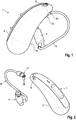
- in einer schematischen Seitenansicht eine Hörvorrichtung mit externem Lautsprecher,
- Fig. 2
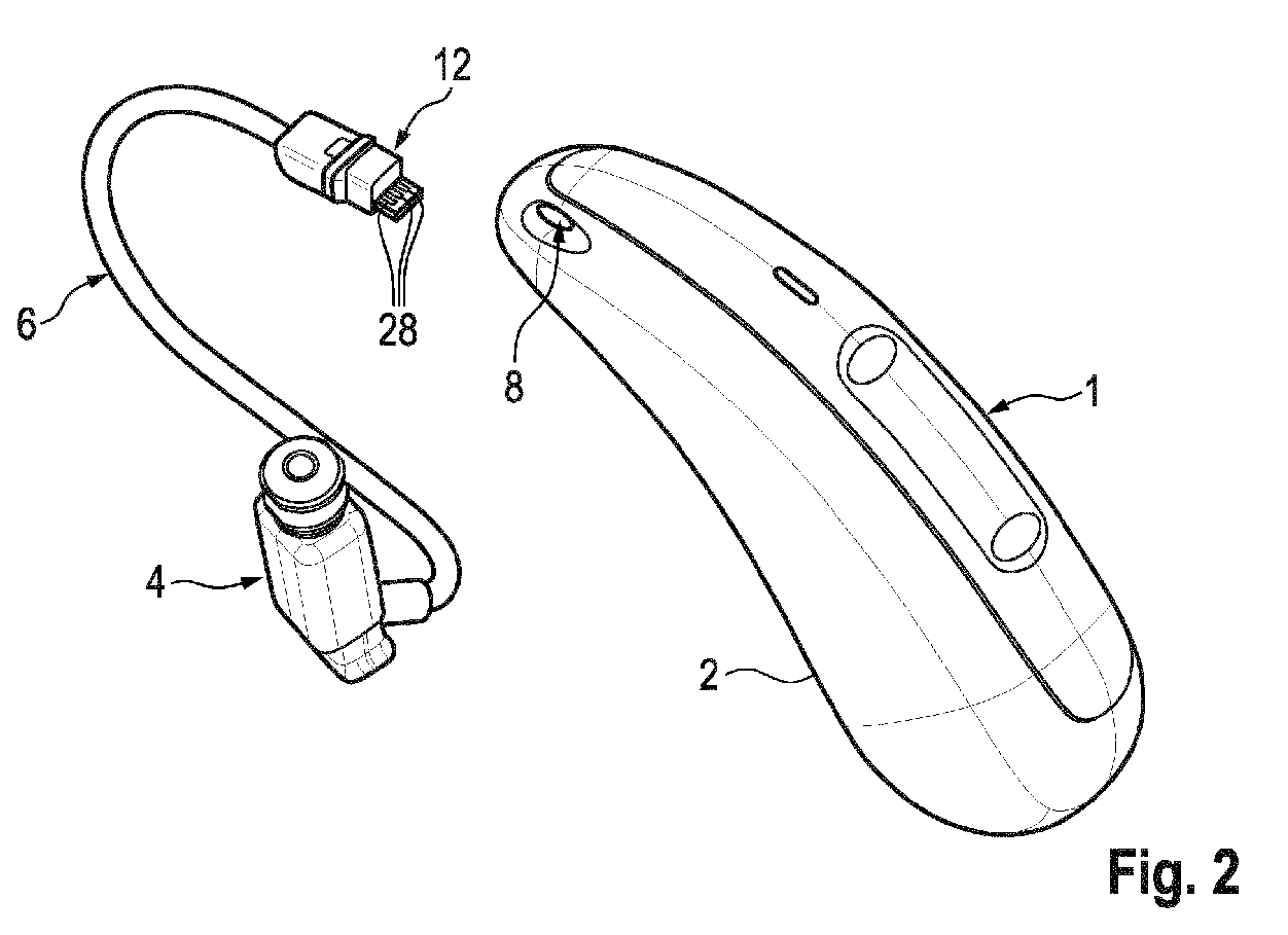
- in einer schematischen Perspektivansicht die Hörvorrichtung mit abgekoppeltem Lautsprecher,
- Fig. 3
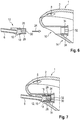
- in einer schematischen Teilschnittdarstellung einen Steckverbinder zur Verbindung des Lautsprechers mit einer Steckverbinder-Aufnahme eines Gehäuses der Hörvorrichtung,
- Fig. 4
- in jeweils einer schematischen ausschnitthaften Frontalansicht den Steckverbinder und die Steckverbinder-Aufnahme,
- Fig. 5
- in einer ausschnitthaften, schematischen Perspektivdarstellung einen weiteren Einsatzzweck der Steckverbinder-Aufnahme,
- Fig. 6, 7
- in Ansicht gemäß
Fig. 3 ein weiteres Ausführungsbeispiel des Steckverbinders sowie der Steckverbinder-Aufnahme in einem unmontierten und einem montierten Zustand, und - Fig. 8
- in einer schematischen Perspektivansicht den Steckverbinder gemäß
Fig. 6 für sich.
- Fig. 1
- a schematic side view of a hearing device with an external loudspeaker,
- Fig. 2
- in a schematic perspective view the hearing device with the loudspeaker disconnected,
- Fig. 3
- a schematic partial sectional view of a connector for connecting the loudspeaker to a connector receptacle of a housing of the hearing apparatus,
- Fig. 4
- the connector and the connector receptacle in each case in a schematic partial front view,
- Fig. 5
- in a fragmentary, schematic perspective illustration, a further purpose of the connector receptacle,
- Fig. 6, 7
- in view according to
Fig. 3 a further embodiment of the connector and the connector receptacle in an unassembled and an assembled state, and - Fig. 8
- in a schematic perspective view the connector according to
Fig. 6 for themselves.
Einander entsprechende Teile sind in allen Figuren stets mit gleichen Bezugszeichen versehen.Corresponding parts are always provided with the same reference symbols in all figures.
In
Um für eine im bestimmungsgemäßen Tragezustand möglichst geradlinig (d. h. entlang einer Horizontalen) nach vorne weisende Mikrofonöffnung 8 ausreichen Platz am Gehäuse 2 zu haben, ist eine Steckverbinder-Aufnahme (kurz: "Buchse 10") zur Aufnahme eines Steckverbinders 12 des Kabels 6 an einer im bestimmungsgemäßen Tragezustand des Hörgeräts 1 nach unten weisenden Fläche 14 angeordnet. Um den eingesteckten Steckverbinder 12 möglichst den Blicken von Dritten zu entziehen und/oder eine Hautreizung aufgrund vorstehender Kanten zu vermeiden, ist die Buchse 10 in die vorstehend genannte Fläche 14 eingelassen, d. h. versenkt. Konkret ist die Buchse 10 derart versenkt, dass im eingesteckten Zustand (s.
In
Der Steckverbinder 12 und die Buchse 10 sind dabei derart ausgebildet, dass die Kopplung durch eine geradlinige Einschubbewegung entlang einer Einsteckrichtung 24 erfolgt.The
Zur Kontaktierung weist der Steckverbinder 12 eine Platte 26 auf, die vorzugsweise von dem Grundkörper 16 umspritzt ist und die auf einer Ober- sowie auf einer Unterseite eine Mehrzahl, hier jeweils drei, von Kontaktelementen 28 trägt. Die Kontaktelemente 28 sind dabei als flächige Elemente in der Oberfläche der Platte 26 angeordnet. In der Buchse 10 sind in nicht näher dargestellter Weise zu den Kontaktelementen 28 korrespondierende Kontaktfedern angeordnet.For contacting, the
Wie aus
In
Eine weitere - auch für sich alleinstehende - Erfindung, die insbesondere eine zur vorstehend beschriebenen Rückhaltevorrichtung zusätzliche oder alternative Ausführung darstellt, betrifft:
- A. Eine Hörvorrichtung ("
Hörgerät 1"), aufweisendein Gehäuse 2, das entlang einer Längsachse gestreckt, im Querschnitt oval ausgebildet und zur Einhausung von elektrischen Komponenten der Hörvorrichtung eingerichtet ist,- mit einem im bestimmungsgemäßen Tragezustand der Hörvorrichtung außerhalb des Gehäuses 2 angeordneten und mit zumindest einem Teil der elektrischen Komponenten verschalteten Lautsprecher 4,
- mit einem
mit dem Lautsprecher 4verbundenen Steckverbinder 12, der wenigsten sechs Kontaktelemente 28 zur Verschaltung des Lautsprechers (4) mit den entsprechenden elektrischen Komponenten trägt, und - mit einer Steckverbinder-Aufnahme ("
Buchse 10") zur Aufnahme des Steckverbinders 12 und Verschaltung der jeweiligen Kontaktelemente 28, insbesondere wobei die Steckverbinder-Aufnahme in einer im bestimmungsgemäßen Tragezustand zur Unterseite gerichteten Fläche 14 desGehäuses 2 angeordnet ist,
- B. Hörvorrichtung nach A,
wobei sowohlam Steckverbinder 12 als auch in der Steckverbinder-Aufnahme jeweils ein Magnet (30, 32), insbesondere ein Dauermagnet, angeordnet ist. - C. Hörvorrichtung nach A,
wobei am Steckverbinder 12 oder in der Steckverbinder-Aufnahme ein Dauermagnet (30, 32) und in der Steckverbinder-Aufnahme bzw.am Steckverbinder 12 paramagnetisches Material angeordnet ist. - D. Hörvorrichtung nach A, B und/oder C,
wobei die Steckverbinder-Aufnahme in die zur Unterseite gerichtete Fläche 14 versenkt ist, so dass der Steckverbinder 12 im bestimmungsgemäßen Einsteckzustand von einer Seitenrichtung her einem Blick entzogen ist. - E. Hörvorrichtung nach A, B, C und/oder D,
wobei der Steckverbinder 12 und die Steckverbinder-Aufnahme komplementär zueinander und selbstausrichtend, insbesondere mit einem unsymmetrischen, vorzugsweise teilweise abgeflachten ovalen Profil, gestaltet sind. - F. Hörvorrichtung nach A, B, C, D und/oder E,
wobei der Steckverbinder 12 einen spritzgegossenen Grundkörper 16 aus einem ersten Kunststoff aufweist und wobei eine umlaufende Dichtung 18 anden Grundkörper 16 aus einem zweiten Kunststoff angeformt ist. - G. Hörvorrichtung nach A, B, C, D, E und/oder F,
wobei der Steckverbinder 12 einen spritzgegossenen Grundkörper 16 aus einem ersten Kunststoff aufweist, wobei der Grundkörper 16 im bestimmungsgemäßen Kopplungszustand schräg zu der zur Unterseite gerichteten Fläche 14 desGehäuses 2 angeordnet ist, und wobei einedem Lautsprecher 4 zugewandte Stirnfläche desGrundkörpers 16, aus derein Lautsprecherverbindungskabel 6 austritt, der zur Unterseite gerichteten Fläche 14 desGehäuses 2 folgend schräg gegenüber einer Kabelaustrittsrichtung des Lautsprecherverbindungskabels 6 angestellt ist. - H. Hörvorrichtung nach A, B, C, D, E, F und/oder G,
wobei der Steckverbinder 12 einen Kontaktträger (der insbesondere einstückigmit dem Grundkörper 16 ausgebildet ist) aufweist, aufdem die Kontaktelemente 28 als beidseitig angeordnete Kontaktflächen ausgebildet sind, insbesondere wobei derMagnet 30 in den Kontaktträger integriert, insbesondere eingespritzt, ist, insbesondere wobei in der Steckverbinder-Aufnahmezu den Kontaktelementen 28 korrespondierende Kontaktfedern 34 angeordnet sind. - I. Hörvorrichtung nach A, B, C, D, E, F, G und/oder H,
wobei der Steckverbinder 12 farblich codiert ist, insbesondere um diesen im Rahmen eines aus dieser und einer weiteren Hörvorrichtung gebildeten Hörvorrichtungssystems von einem dem anderen Ohr zugewiesenen Steckverbinder unterschieden zu können.
- A. Having a hearing device ("
Hearing Aid 1")- a
housing 2, which is stretched along a longitudinal axis, has an oval cross-section and is designed to house electrical components of the hearing device, - with a
loudspeaker 4 which is arranged outside thehousing 2 when the hearing device is worn as intended and connected to at least some of the electrical components, - with a
connector 12 connected to theloudspeaker 4, which carries at least sixcontact elements 28 for interconnecting the loudspeaker (4) with the corresponding electrical components, and - with a plug connector receptacle ("
socket 10") for receiving theplug connector 12 and interconnection of therespective contact elements 28, in particular wherein the plug connector receptacle is arranged in asurface 14 of thehousing 2 directed towards the underside in the intended wearing state,
plug connector 12 and the plug connector receptacle are designed such that aninsertion direction 24 runs from a front side to a rear side when worn as intended, and theplug connector 12 and the plug connector receptacle are set up for mutual magnetic retention. (The restraint device described above is therefore implemented here in particular by the magnetic attraction between theconnector 12 and the connector receptacle.) - a
- B. Hearing device according to A,
a magnet (30, 32), in particular a permanent magnet, being arranged both on theconnector 12 and in the connector receptacle. - C. hearing aid according to A,
a permanent magnet (30, 32) being arranged on theplug connector 12 or in the plug connector receptacle and paramagnetic material being arranged in the plug connector receptacle or on theplug connector 12. - D. hearing aid according to A, B and / or C,
wherein the connector receptacle is sunk into thesurface 14 facing the underside, so that theconnector 12 is hidden from view from one side direction in the intended plug-in state. - E. hearing aid according to A, B, C and / or D,
wherein theconnector 12 and the connector receptacle are designed to be complementary to one another and self-aligning, in particular with an asymmetrical, preferably partially flattened oval profile. - F. Hearing device according to A, B, C, D and / or E,
wherein theplug connector 12 has an injection-moldedbase body 16 made of a first plastic and wherein acircumferential seal 18 is molded onto thebase body 16 made of a second plastic. - G. hearing aid according to A, B, C, D, E and / or F,
Theconnector 12 has an injection-moldedbase body 16 made of a first plastic, thebase body 16 in the intended coupling state being arranged at an angle to thesurface 14 of thehousing 2 facing the underside, and with an end face of thebase body 16 facing theloudspeaker 4 from which aLoudspeaker connection cable 6 exits, which is positioned following thesurface 14 of thehousing 2 facing the underside at an angle with respect to a cable exit direction of theloudspeaker connection cable 6. - H. Hearing device according to A, B, C, D, E, F and / or G,
wherein theconnector 12 has a contact carrier (which is in particular formed in one piece with the base body 16) on which thecontact elements 28 are formed as contact surfaces arranged on both sides, in particular wherein themagnet 30 is integrated, in particular injected, into the contact carrier, in particular wherein in the Connector receptacle to thecontact elements 28 corresponding contact springs 34 are arranged. - I. Hearing device according to A, B, C, D, E, F, G and / or H,
wherein theconnector 12 is color-coded, in particular in order to be able to distinguish it from a connector assigned to the other ear within the framework of a hearing device system formed from this and a further hearing device.
Der Gegenstand der Erfindung ist nicht die vorstehend beschriebenen Ausführungsbeispiele beschränkt. Vielmehr können weitere Ausführungsformen der Erfindung von dem Fachmann aus der vorstehenden Beschreibung abgeleitet werden.The subject matter of the invention is not limited to the exemplary embodiments described above. Rather, further embodiments of the invention can be derived from the above description by a person skilled in the art.
- 11
- HörgerätHearing aid
- 22
- Gehäusecasing
- 44th
- Lautsprecherspeaker
- 66th
- Kabelcable
- 88th
- MikrofonöffnungMicrophone opening
- 1010
- BuchseRifle
- 1212th
- SteckverbinderConnectors
- 1414th
- Flächearea
- 1616
- GrundkörperBase body
- 1818th
- Dichtungpoetry
- 2020th
- NutGroove
- 2222nd
- DrahtfederWire spring
- 2424
- EinsteckrichtungInsertion direction
- 2626th
- Platteplate
- 2828
- KontaktelementContact element
- 3030th
- Magnetmagnet
- 3232
- Magnetmagnet
- 3434
- KontaktfederContact spring
Claims (10)
wobei die Steckverbinder-Aufnahme (10) in die zur Unterseite gerichtete Fläche (14) versenkt ist, so dass der Steckverbinder (12) im bestimmungsgemäßen Einsteckzustand von einer Seitenrichtung her einem Blick entzogen ist.Hearing device (1) according to claim 1,
wherein the connector receptacle (10) is sunk into the surface (14) directed towards the underside, so that the connector (12) is hidden from view from one side when plugged in as intended.
wobei der Steckverbinder (12) und die Steckverbinder-Aufnahme (10) komplementär zueinander und selbstausrichtend, insbesondere mit einem unsymmetrischen, vorzugsweise teilweise abgeflachten ovalen Profil, gestaltet sind.Hearing device (1) according to claim 1 or 2,
wherein the connector (12) and the connector receptacle (10) are designed to be complementary to one another and self-aligning, in particular with an asymmetrical, preferably partially flattened oval profile.
wobei der Steckverbinder (12) und die Steckverbinder-Aufnahme (10) jeweils einen Teil (20,22) einer in Einsteckrichtung (24) automatisch betätigbaren Rückhaltevorrichtung aufweisen.Hearing device (1) according to one of claims 1 to 3,
wherein the plug connector (12) and the plug connector receptacle (10) each have a part (20, 22) of a retaining device that can be automatically actuated in the insertion direction (24).
wobei der Steckverbinder (12) eine Nut (20) aufweist, wobei die Steckverbinder-Aufnahme (10) eine Drahtfeder (22) aufweist, die im bestimmungsgemäßen Kopplungszustand in die Nut (20) eingreift.Hearing device (1) according to claim 4,
wherein the connector (12) has a groove (20), the connector receptacle (10) having a wire spring (22) which engages in the groove (20) in the intended coupling state.
wobei der Steckverbinder (12) einen spritzgegossenen Grundkörper (16) aus einem ersten Kunststoff aufweist und wobei eine umlaufende Dichtung (18) an den Grundkörper (16) aus einem zweiten Kunststoff angeformt ist.Hearing device (1) according to one of claims 1 to 5,
wherein the connector (12) has an injection-molded base body (16) made of a first plastic and wherein a circumferential seal (18) is molded onto the base body (16) made of a second plastic.
wobei der Steckverbinder (12) einen spritzgegossenen Grundkörper (16) aus einem ersten Kunststoff aufweist, wobei der Grundkörper (16) im bestimmungsgemäßen Kopplungszustand schräg zu der zur Unterseite gerichteten Fläche (14) des Gehäuses (2) angeordnet ist, und wobei eine dem Lautsprecher (4) zugewandte Stirnfläche des Grundkörpers (16), aus der ein Lautsprecherverbindungskabel (6) austritt, der zur Unterseite gerichteten Fläche (14) des Gehäuses (2) folgend schräg gegenüber einer Kabelaustrittsrichtung des Lautsprecherverbindungskabels (6) angestellt ist.Hearing device (1) according to one of claims 1 to 6,
wherein the connector (12) has an injection-molded base body (16) made of a first plastic, the base body (16) in the intended coupling state being arranged at an angle to the surface (14) of the housing (2) facing the underside, and one being the loudspeaker (4) facing end face of the base body (16) from which a loudspeaker connection cable (6) exits, following the surface (14) of the housing (2) facing the underside, which is positioned obliquely with respect to a cable exit direction of the loudspeaker connection cable (6).
wobei der Steckverbinder (12) einen Kontaktträger in Form einer auf der dem Lautsprecher (4) abgewandten Stirnfläche vorstehenden Platte (26) aufweist, auf der die Kontaktelemente (28) als beidseitig angeordnete Kontaktflächen ausgebildet sind.Hearing device (1) according to one of claims 1 to 7,
wherein the plug connector (12) has a contact carrier in the form of a plate (26) protruding on the end face facing away from the loudspeaker (4), on which the contact elements (28) are designed as contact surfaces arranged on both sides.
wobei die Steckverbinder-Aufnahme (10) korrespondierende Federkontakte zur Kontaktierung einer jeden Kontaktfläche aufweist.Hearing device (1) according to claim 8,
wherein the connector receptacle (10) has corresponding spring contacts for contacting each contact surface.
wobei der Steckverbinder (12) eine Kodierung, insbesondere eine farbliche Kodierung, zur Anzeige der dem entsprechenden Ohr eines Nutzers zugeordneten Seite aufweist.Hearing device (1) according to one of claims 1 to 9,
wherein the connector (12) has a coding, in particular a color coding, for displaying the side assigned to the corresponding ear of a user.
Applications Claiming Priority (1)
| Application Number | Priority Date | Filing Date | Title |
|---|---|---|---|
| DE102020205439.8A DE102020205439A1 (en) | 2020-04-29 | 2020-04-29 | Hearing aid |
Publications (3)
| Publication Number | Publication Date |
|---|---|
| EP3905723A1 true EP3905723A1 (en) | 2021-11-03 |
| EP3905723B1 EP3905723B1 (en) | 2024-10-23 |
| EP3905723C0 EP3905723C0 (en) | 2024-10-23 |
Family
ID=75529903
Family Applications (1)
| Application Number | Title | Priority Date | Filing Date |
|---|---|---|---|
| EP21168412.1A Active EP3905723B1 (en) | 2020-04-29 | 2021-04-14 | Hearing device |
Country Status (4)
| Country | Link |
|---|---|
| US (1) | US11729558B2 (en) |
| EP (1) | EP3905723B1 (en) |
| CN (1) | CN113573223A (en) |
| DE (1) | DE102020205439A1 (en) |
Families Citing this family (2)
| Publication number | Priority date | Publication date | Assignee | Title |
|---|---|---|---|---|
| DE202022101121U1 (en) | 2022-03-01 | 2022-03-09 | Sonova Ag | Behind-the-ear part for a hearing aid |
| CN223219182U (en) * | 2024-04-11 | 2025-08-12 | 深圳市韶音听力科技有限公司 | A wearable device |
Citations (5)
| Publication number | Priority date | Publication date | Assignee | Title |
|---|---|---|---|---|
| US20120014549A1 (en) * | 2010-07-14 | 2012-01-19 | Starkey Laboratories, Inc. | Receiver-in-canal hearing device cable connections |
| EP2456235A1 (en) * | 2010-11-17 | 2012-05-23 | Yamaichi Electronics Deutschland GmbH | Hearing aid, connector, use of a connector and system for connecting a hearing aid with a cable |
| DE102017128117A1 (en) * | 2017-11-28 | 2019-05-29 | Ear-Technic GmbH | Modular hearing aid |
| EP3503587A1 (en) * | 2017-12-22 | 2019-06-26 | GN Hearing A/S | Hearing aid connector |
| EP3537731A1 (en) * | 2018-03-09 | 2019-09-11 | Oticon A/s | Speaker unit for a hearing aid device system, and hearing aid device system |
Family Cites Families (8)
| Publication number | Priority date | Publication date | Assignee | Title |
|---|---|---|---|---|
| DE3802250C1 (en) | 1988-01-27 | 1988-10-27 | Sonar Design & Hoertechnik Gmbh, 4400 Muenster, De | |
| US7110562B1 (en) * | 2001-08-10 | 2006-09-19 | Hear-Wear Technologies, Llc | BTE/CIC auditory device and modular connector system therefor |
| JP5518214B2 (en) * | 2010-02-11 | 2014-06-11 | シーメンス メディカル インストゥルメンツ ピーティーイー リミテッド | Hearing aid with plug-in connector |
| DE202013000547U1 (en) | 2013-01-18 | 2013-02-25 | Siemens Medical Instruments Pte. Ltd. | Hearing instrument housing with plug connection |
| DE102013225429A1 (en) | 2013-12-10 | 2015-06-11 | Siemens Medical Instruments Pte. Ltd. | BTE hearing instrument with housing and carrying hook |
| JP6408243B2 (en) | 2014-04-23 | 2018-10-17 | 丸山 誠二 | Ear proximity speaker device |
| US10887706B2 (en) * | 2015-06-29 | 2021-01-05 | Hear-Wear Technologies LLC | Transducer modules for auditory communication devices and auditory communication devices |
| EP3226582A1 (en) * | 2016-03-29 | 2017-10-04 | Oticon Medical A/S | Hearing device comprising modular engagement means |
-
2020
- 2020-04-29 DE DE102020205439.8A patent/DE102020205439A1/en active Pending
-
2021
- 2021-04-14 EP EP21168412.1A patent/EP3905723B1/en active Active
- 2021-04-29 CN CN202110473257.9A patent/CN113573223A/en active Pending
- 2021-04-29 US US17/243,846 patent/US11729558B2/en active Active
Patent Citations (5)
| Publication number | Priority date | Publication date | Assignee | Title |
|---|---|---|---|---|
| US20120014549A1 (en) * | 2010-07-14 | 2012-01-19 | Starkey Laboratories, Inc. | Receiver-in-canal hearing device cable connections |
| EP2456235A1 (en) * | 2010-11-17 | 2012-05-23 | Yamaichi Electronics Deutschland GmbH | Hearing aid, connector, use of a connector and system for connecting a hearing aid with a cable |
| DE102017128117A1 (en) * | 2017-11-28 | 2019-05-29 | Ear-Technic GmbH | Modular hearing aid |
| EP3503587A1 (en) * | 2017-12-22 | 2019-06-26 | GN Hearing A/S | Hearing aid connector |
| EP3537731A1 (en) * | 2018-03-09 | 2019-09-11 | Oticon A/s | Speaker unit for a hearing aid device system, and hearing aid device system |
Also Published As
| Publication number | Publication date |
|---|---|
| EP3905723B1 (en) | 2024-10-23 |
| US20210345049A1 (en) | 2021-11-04 |
| US11729558B2 (en) | 2023-08-15 |
| DE102020205439A1 (en) | 2021-11-04 |
| CN113573223A (en) | 2021-10-29 |
| EP3905723C0 (en) | 2024-10-23 |
Similar Documents
| Publication | Publication Date | Title |
|---|---|---|
| EP2540098B1 (en) | Connector for a ric-bte hearing instrument and ric-bte hearing instrument | |
| DE68918327T3 (en) | Programming interface for hearing aids. | |
| EP2285136B1 (en) | Hearing aid with replaceable earpiece | |
| DE102010002176A1 (en) | contactor | |
| EP3905723B1 (en) | Hearing device | |
| DE102007008551A1 (en) | Hearing device with magnetically attached battery compartment | |
| EP1993323B1 (en) | Earpiece for a hearing aid with bayonet fixing | |
| EP3196684A1 (en) | Connector | |
| EP2040488A2 (en) | Tool for inserting an earpiece of a hearing aid into an auditory canal | |
| DE2751755C2 (en) | Line connector for a hearing aid | |
| EP2456235B1 (en) | Hearing aid, connector, use of a connector and system for connecting a hearing aid with a cable | |
| DE102010040930B4 (en) | Hearing aid with a battery charger | |
| DE3207256A1 (en) | HOERHILFEGERAET | |
| DE102012101609A1 (en) | Assembly module for wall mounting of LCD touch panel of display unit that is utilized for displaying information about e.g. parameter of building equipment, has diaphragm connected with base element using locking element | |
| DE102008008670A1 (en) | Charger for a hearing device with a movable charging contact | |
| DE102008024515B3 (en) | Hearing aid e.g. behind-the-ear hearing aid, for assisting hearing impaired persons, has electrical contact arranged in opening of housing, contactable from outside of housing and connected with electronic circuit | |
| WO2015036305A1 (en) | Plug-type connector | |
| EP0244671A1 (en) | Method and arrangement for carrying out an acoustic comparison measurement | |
| DE102012016154A1 (en) | door mirror | |
| DE102005009377B3 (en) | Hearing aid, has two housings respectively accommodating microphone and amplifier, and loudspeaker, where mechanical connection between housings is realized by bayonet-fastener typical groove | |
| EP0334837A3 (en) | Hearing aid with audio input plug | |
| CH668154A5 (en) | Hearing aid with electroacoustic transducer - fits behind ear and has facility for plugging in range of operational mode elements | |
| EP3419312B1 (en) | Hearing aid | |
| DE102021205471B3 (en) | hearing device | |
| EP2018078A2 (en) | Hearing aid with an attachment device for attaching an audio shoe and corresponding audio shoe |
Legal Events
| Date | Code | Title | Description |
|---|---|---|---|
| PUAI | Public reference made under article 153(3) epc to a published international application that has entered the european phase |
Free format text: ORIGINAL CODE: 0009012 |
|
| STAA | Information on the status of an ep patent application or granted ep patent |
Free format text: STATUS: THE APPLICATION HAS BEEN PUBLISHED |
|
| AK | Designated contracting states |
Kind code of ref document: A1 Designated state(s): AL AT BE BG CH CY CZ DE DK EE ES FI FR GB GR HR HU IE IS IT LI LT LU LV MC MK MT NL NO PL PT RO RS SE SI SK SM TR |
|
| B565 | Issuance of search results under rule 164(2) epc |
Effective date: 20210922 |
|
| STAA | Information on the status of an ep patent application or granted ep patent |
Free format text: STATUS: REQUEST FOR EXAMINATION WAS MADE |
|
| 17P | Request for examination filed |
Effective date: 20220218 |
|
| RBV | Designated contracting states (corrected) |
Designated state(s): AL AT BE BG CH CY CZ DE DK EE ES FI FR GB GR HR HU IE IS IT LI LT LU LV MC MK MT NL NO PL PT RO RS SE SI SK SM TR |
|
| STAA | Information on the status of an ep patent application or granted ep patent |
Free format text: STATUS: EXAMINATION IS IN PROGRESS |
|
| RIN1 | Information on inventor provided before grant (corrected) |
Inventor name: KRAL, HOLGER Inventor name: DING, LIT SONG GLEN Inventor name: ANG, THAI WEE Inventor name: BIN SHITH, MUHAMMAD SHAHID |
|
| 17Q | First examination report despatched |
Effective date: 20220804 |
|
| GRAP | Despatch of communication of intention to grant a patent |
Free format text: ORIGINAL CODE: EPIDOSNIGR1 |
|
| STAA | Information on the status of an ep patent application or granted ep patent |
Free format text: STATUS: GRANT OF PATENT IS INTENDED |
|
| INTG | Intention to grant announced |
Effective date: 20240627 |
|
| GRAS | Grant fee paid |
Free format text: ORIGINAL CODE: EPIDOSNIGR3 |
|
| GRAA | (expected) grant |
Free format text: ORIGINAL CODE: 0009210 |
|
| STAA | Information on the status of an ep patent application or granted ep patent |
Free format text: STATUS: THE PATENT HAS BEEN GRANTED |
|
| AK | Designated contracting states |
Kind code of ref document: B1 Designated state(s): AL AT BE BG CH CY CZ DE DK EE ES FI FR GB GR HR HU IE IS IT LI LT LU LV MC MK MT NL NO PL PT RO RS SE SI SK SM TR |
|
| REG | Reference to a national code |
Ref country code: GB Ref legal event code: FG4D Free format text: NOT ENGLISH |
|
| REG | Reference to a national code |
Ref country code: CH Ref legal event code: EP |
|
| REG | Reference to a national code |
Ref country code: DE Ref legal event code: R096 Ref document number: 502021005543 Country of ref document: DE |
|
| REG | Reference to a national code |
Ref country code: IE Ref legal event code: FG4D Free format text: LANGUAGE OF EP DOCUMENT: GERMAN |
|
| U01 | Request for unitary effect filed |
Effective date: 20241023 |
|
| U07 | Unitary effect registered |
Designated state(s): AT BE BG DE DK EE FI FR IT LT LU LV MT NL PT RO SE SI Effective date: 20241107 |
|
| PG25 | Lapsed in a contracting state [announced via postgrant information from national office to epo] |
Ref country code: IS Free format text: LAPSE BECAUSE OF FAILURE TO SUBMIT A TRANSLATION OF THE DESCRIPTION OR TO PAY THE FEE WITHIN THE PRESCRIBED TIME-LIMIT Effective date: 20250223 Ref country code: HR Free format text: LAPSE BECAUSE OF FAILURE TO SUBMIT A TRANSLATION OF THE DESCRIPTION OR TO PAY THE FEE WITHIN THE PRESCRIBED TIME-LIMIT Effective date: 20241023 |
|
| PG25 | Lapsed in a contracting state [announced via postgrant information from national office to epo] |
Ref country code: ES Free format text: LAPSE BECAUSE OF FAILURE TO SUBMIT A TRANSLATION OF THE DESCRIPTION OR TO PAY THE FEE WITHIN THE PRESCRIBED TIME-LIMIT Effective date: 20241023 |
|
| PG25 | Lapsed in a contracting state [announced via postgrant information from national office to epo] |
Ref country code: NO Free format text: LAPSE BECAUSE OF FAILURE TO SUBMIT A TRANSLATION OF THE DESCRIPTION OR TO PAY THE FEE WITHIN THE PRESCRIBED TIME-LIMIT Effective date: 20250123 |
|
| U20 | Renewal fee for the european patent with unitary effect paid |
Year of fee payment: 5 Effective date: 20250319 |
|
| PG25 | Lapsed in a contracting state [announced via postgrant information from national office to epo] |
Ref country code: GR Free format text: LAPSE BECAUSE OF FAILURE TO SUBMIT A TRANSLATION OF THE DESCRIPTION OR TO PAY THE FEE WITHIN THE PRESCRIBED TIME-LIMIT Effective date: 20250124 |
|
| PG25 | Lapsed in a contracting state [announced via postgrant information from national office to epo] |
Ref country code: PL Free format text: LAPSE BECAUSE OF FAILURE TO SUBMIT A TRANSLATION OF THE DESCRIPTION OR TO PAY THE FEE WITHIN THE PRESCRIBED TIME-LIMIT Effective date: 20241023 |
|
| PG25 | Lapsed in a contracting state [announced via postgrant information from national office to epo] |
Ref country code: RS Free format text: LAPSE BECAUSE OF FAILURE TO SUBMIT A TRANSLATION OF THE DESCRIPTION OR TO PAY THE FEE WITHIN THE PRESCRIBED TIME-LIMIT Effective date: 20250123 |
|
| PG25 | Lapsed in a contracting state [announced via postgrant information from national office to epo] |
Ref country code: SM Free format text: LAPSE BECAUSE OF FAILURE TO SUBMIT A TRANSLATION OF THE DESCRIPTION OR TO PAY THE FEE WITHIN THE PRESCRIBED TIME-LIMIT Effective date: 20241023 |
|
| PGFP | Annual fee paid to national office [announced via postgrant information from national office to epo] |
Ref country code: CH Payment date: 20250501 Year of fee payment: 5 |
|
| PG25 | Lapsed in a contracting state [announced via postgrant information from national office to epo] |
Ref country code: SK Free format text: LAPSE BECAUSE OF FAILURE TO SUBMIT A TRANSLATION OF THE DESCRIPTION OR TO PAY THE FEE WITHIN THE PRESCRIBED TIME-LIMIT Effective date: 20241023 |
|
| PG25 | Lapsed in a contracting state [announced via postgrant information from national office to epo] |
Ref country code: CZ Free format text: LAPSE BECAUSE OF FAILURE TO SUBMIT A TRANSLATION OF THE DESCRIPTION OR TO PAY THE FEE WITHIN THE PRESCRIBED TIME-LIMIT Effective date: 20241023 |
|
| PLBE | No opposition filed within time limit |
Free format text: ORIGINAL CODE: 0009261 |
|
| STAA | Information on the status of an ep patent application or granted ep patent |
Free format text: STATUS: NO OPPOSITION FILED WITHIN TIME LIMIT |
|
| 26N | No opposition filed |
Effective date: 20250724 |
|
| PG25 | Lapsed in a contracting state [announced via postgrant information from national office to epo] |
Ref country code: MC Free format text: LAPSE BECAUSE OF FAILURE TO SUBMIT A TRANSLATION OF THE DESCRIPTION OR TO PAY THE FEE WITHIN THE PRESCRIBED TIME-LIMIT Effective date: 20241023 |
|
| PGFP | Annual fee paid to national office [announced via postgrant information from national office to epo] |
Ref country code: GB Payment date: 20260319 Year of fee payment: 6 |
|
| PG25 | Lapsed in a contracting state [announced via postgrant information from national office to epo] |
Ref country code: IE Free format text: LAPSE BECAUSE OF NON-PAYMENT OF DUE FEES Effective date: 20250414 |
|
| U20 | Renewal fee for the european patent with unitary effect paid |
Year of fee payment: 6 Effective date: 20260319 |