EP3905723B1 - Dispositif auditif - Google Patents
Dispositif auditif Download PDFInfo
- Publication number
- EP3905723B1 EP3905723B1 EP21168412.1A EP21168412A EP3905723B1 EP 3905723 B1 EP3905723 B1 EP 3905723B1 EP 21168412 A EP21168412 A EP 21168412A EP 3905723 B1 EP3905723 B1 EP 3905723B1
- Authority
- EP
- European Patent Office
- Prior art keywords
- plug connector
- hearing device
- loudspeaker
- housing
- intended
- Prior art date
- Legal status (The legal status is an assumption and is not a legal conclusion. Google has not performed a legal analysis and makes no representation as to the accuracy of the status listed.)
- Active
Links
Images


Classifications
-
- H—ELECTRICITY
- H04—ELECTRIC COMMUNICATION TECHNIQUE
- H04R—LOUDSPEAKERS, MICROPHONES, GRAMOPHONE PICK-UPS OR LIKE ACOUSTIC ELECTROMECHANICAL TRANSDUCERS; ELECTRIC HEARING AIDS; PUBLIC ADDRESS SYSTEMS
- H04R25/00—Electric hearing aids
- H04R25/55—Electric hearing aids using an external connection, either wireless or wired
- H04R25/556—External connectors, e.g. plugs or modules
-
- H—ELECTRICITY
- H01—ELECTRIC ELEMENTS
- H01R—ELECTRICALLY-CONDUCTIVE CONNECTIONS; STRUCTURAL ASSOCIATIONS OF A PLURALITY OF MUTUALLY-INSULATED ELECTRICAL CONNECTING ELEMENTS; COUPLING DEVICES; CURRENT COLLECTORS
- H01R13/00—Details of coupling devices of the kinds covered by groups H01R12/70 or H01R24/00 - H01R33/00
- H01R13/46—Bases; Cases
- H01R13/52—Dustproof, splashproof, drip-proof, waterproof, or flameproof cases
- H01R13/5219—Sealing means between coupling parts, e.g. interfacial seal
-
- H—ELECTRICITY
- H01—ELECTRIC ELEMENTS
- H01R—ELECTRICALLY-CONDUCTIVE CONNECTIONS; STRUCTURAL ASSOCIATIONS OF A PLURALITY OF MUTUALLY-INSULATED ELECTRICAL CONNECTING ELEMENTS; COUPLING DEVICES; CURRENT COLLECTORS
- H01R13/00—Details of coupling devices of the kinds covered by groups H01R12/70 or H01R24/00 - H01R33/00
- H01R13/62—Means for facilitating engagement or disengagement of coupling parts or for holding them in engagement
- H01R13/629—Additional means for facilitating engagement or disengagement of coupling parts, e.g. aligning or guiding means, levers, gas pressure electrical locking indicators, manufacturing tolerances
- H01R13/631—Additional means for facilitating engagement or disengagement of coupling parts, e.g. aligning or guiding means, levers, gas pressure electrical locking indicators, manufacturing tolerances for engagement only
-
- H—ELECTRICITY
- H04—ELECTRIC COMMUNICATION TECHNIQUE
- H04R—LOUDSPEAKERS, MICROPHONES, GRAMOPHONE PICK-UPS OR LIKE ACOUSTIC ELECTROMECHANICAL TRANSDUCERS; ELECTRIC HEARING AIDS; PUBLIC ADDRESS SYSTEMS
- H04R25/00—Electric hearing aids
- H04R25/60—Mounting or interconnection of hearing aid parts, e.g. inside tips, housings or to ossicles
- H04R25/602—Mounting or interconnection of hearing aid parts, e.g. inside tips, housings or to ossicles of batteries
-
- H—ELECTRICITY
- H04—ELECTRIC COMMUNICATION TECHNIQUE
- H04R—LOUDSPEAKERS, MICROPHONES, GRAMOPHONE PICK-UPS OR LIKE ACOUSTIC ELECTROMECHANICAL TRANSDUCERS; ELECTRIC HEARING AIDS; PUBLIC ADDRESS SYSTEMS
- H04R25/00—Electric hearing aids
- H04R25/60—Mounting or interconnection of hearing aid parts, e.g. inside tips, housings or to ossicles
- H04R25/604—Mounting or interconnection of hearing aid parts, e.g. inside tips, housings or to ossicles of acoustic or vibrational transducers
-
- H—ELECTRICITY
- H04—ELECTRIC COMMUNICATION TECHNIQUE
- H04R—LOUDSPEAKERS, MICROPHONES, GRAMOPHONE PICK-UPS OR LIKE ACOUSTIC ELECTROMECHANICAL TRANSDUCERS; ELECTRIC HEARING AIDS; PUBLIC ADDRESS SYSTEMS
- H04R25/00—Electric hearing aids
- H04R25/60—Mounting or interconnection of hearing aid parts, e.g. inside tips, housings or to ossicles
- H04R25/607—Mounting or interconnection of hearing aid parts, e.g. inside tips, housings or to ossicles of earhooks
-
- H—ELECTRICITY
- H04—ELECTRIC COMMUNICATION TECHNIQUE
- H04R—LOUDSPEAKERS, MICROPHONES, GRAMOPHONE PICK-UPS OR LIKE ACOUSTIC ELECTROMECHANICAL TRANSDUCERS; ELECTRIC HEARING AIDS; PUBLIC ADDRESS SYSTEMS
- H04R2225/00—Details of deaf aids covered by H04R25/00, not provided for in any of its subgroups
- H04R2225/021—Behind the ear [BTE] hearing aids
Definitions
- the invention relates to a hearing device, in particular a hearing aid.
- Hearing aids are usually used to output a sound signal to the hearing of the person wearing the hearing aid.
- the output is made by means of an output transducer, usually acoustically via airborne sound using a loudspeaker (also referred to as a "receiver” or “earpiece”).
- a loudspeaker also referred to as a "receiver” or “earpiece”
- hearing aids are often used as so-called hearing aids (also called hearing aids for short).
- the hearing aids normally comprise an acoustic input transducer (in particular a microphone) and a signal processor that is set up to process the input signal (also called a microphone signal) generated by the input transducer from the ambient sound using at least one signal processing algorithm that is usually stored for the specific user in such a way that any hearing loss of the person wearing the hearing aid is at least partially compensated.
- the output transducer can be a loudspeaker or alternatively a so-called bone conduction receiver or a cochlear implant, which are set up to mechanically or electrically couple the sound signal into the hearing of the person wearing the hearing aid.
- hearing aids also includes devices such as so-called tinnitus maskers, headsets, headphones and the like.
- Hearing devices are regularly used in the form of devices that are worn behind the ear (also: “BTE") or in the ear (also: “ITE”).
- BTEs can be divided into devices that have the loudspeaker in the BTE housing, and those devices that who have to wear the loudspeaker externally, in particular in the ear canal as intended. The latter are often also referred to as "RIC"("receiver in canal”) hearing aids.
- a connecting cable is required between the electrical components arranged in the BTE housing (e.g. the respective microphone, preferably a signal processor that contains the above-mentioned signal processing algorithm) and the loudspeaker.
- This connecting cable is usually coupled to the BTE housing, which is usually roughly banana-shaped, in the area of the "tip".
- a corresponding connector is often designed in such a way that microphones facing forward are not covered when the hearing aid is worn as intended.
- a connection between the connecting cable and the BTE housing that is as secure as possible, i.e. stable and permanent against accidental loosening, is also required.
- a RIC hearing aid that has a button-like BTE housing.
- EP 3 537 731 A1 A loudspeaker unit is disclosed which can be detachably attached to a BTE housing.
- EP 3 537 731 A1 a flat plug.
- the invention is based on the object of providing an improved connection between an external loudspeaker and a housing of a hearing device.
- the hearing device has a housing that is stretched along a longitudinal axis, oval in cross-section and designed to house electrical components of the hearing device.
- the hearing device also has a loudspeaker that is arranged outside the housing when the hearing device is in the intended wearing state and is connected to at least some of the electrical components.
- the hearing device also has a plug connector that is connected to the loudspeaker, in particular by means of a loudspeaker connection cable, and that carries at least six contact elements for connecting the loudspeaker to the corresponding electrical components.
- the hearing device also has a plug connector receptacle for receiving the plug connector and connecting the respective contact elements.
- This plug connector receptacle is arranged in a surface of the housing that faces the underside when the device is in the intended wearing state.
- the plug connector and the plug connector receptacle are also designed such that a plug-in direction runs from a front side to a back side when the device is in the intended wearing state.
- the electrical components are preferably at least one microphone and a signal processor for processing signals emitted by the respective microphone.
- the hearing device also comprises a preferably rechargeable battery unit, also referred to as a battery pack, as a (particularly further) electrical component.
- the battery unit preferably in turn comprises charging electronics for controlling and monitoring a discharging or charging process.
- the hearing device preferably forms a hearing aid, also referred to as a "hearing aid" for short.
- the hearing device forms a RIC hearing aid or RIC-BTE, since the housing described above is preferably intended to be worn behind the ear.
- the external loudspeaker on the other hand, is intended to be worn in the ear, preferably in the ear canal.
- the connector receptacle is recessed into the surface of the housing facing the underside, preferably in such a way that the connector is hidden from view from one side when plugged in as intended.
- the connector is "invisible” when worn as intended, but on the other hand it also advantageously creates a surface that is as flat as possible on the user's ear.
- the connector and the connector receptacle are designed to complement each other and are self-aligning.
- both have an asymmetrical, preferably partially flattened oval profile. This makes it easy to position the connector clearly in relation to the housing during assembly and prevents incorrect contact of the contact elements.
- the connector and the connector receptacle each have a part of a retaining device that can be automatically actuated in the insertion direction. This advantageously allows the connector to be locked in the housing by an additional measure, for example by A locking bolt that is pushed across the housing is no longer necessary.
- the connector has a groove as part of the retaining device and the connector receptacle has a wire spring (which is preferably designed in the manner of a C-ring).
- This wire spring engages in the groove in the intended coupling state, so that a reversibly effective positive connection is formed to prevent the connector from being accidentally pulled off.
- the connector in addition to the seal described above, has an injection-molded base body (in particular the one described above).
- this base body In the intended coupling state, this base body is arranged at an angle to the surface of the housing facing the underside. Therefore, an end face of the base body facing the loudspeaker, from which the loudspeaker connection cable emerges, is set at an angle to a cable exit direction of the loudspeaker connection cable, following the surface of the housing facing the underside.
- this end face of the connector is aligned at an angle, so that in the intended coupling state the end face is essentially (i.e. with minor deviations) parallel to the downward-facing surface and preferably is also arranged lying in its plane.
- the connector in particular its base body, is only slightly larger in cross-section than the loudspeaker connection cable, for example up to a factor of two.
- the connector plugged into the connector receptacle takes up only a small amount of space on the housing, so that a particularly large amount of space is available on or in the housing for positioning the respective microphone or microphones and the associated microphone opening and/or the silhouette of the hearing device can be reduced.
- the connector has a contact carrier in the form of a plate protruding from the front surface facing away from the loudspeaker (in particular the base body).
- the contact elements described above are designed as contact surfaces on this plate and are arranged in particular distributed on both sides.
- This plate represents a comparatively stable means of contacting and is similar in principle to a contact carrier of a USB 2.0 Type A plug.
- the connector receptacle has corresponding spring contacts for contacting each of the contact surfaces described above.
- the connector has a coding, in particular a color coding, to indicate the side assigned to the corresponding ear of a user.
- a coding in particular a color coding
- the connector has a coding, in particular a color coding, to indicate the side assigned to the corresponding ear of a user.
- a hearing device e.g. a binaural hearing aid system
- the case may be that a different loudspeaker is used for each ear.
- the loudspeaker connection cable is pre-bent for a connection between the housing worn behind the ear and the loudspeaker that is as invisible and non-disruptive as possible.
- the coding enables the risk of the device being used the wrong way round to be reduced.
- the connector receptacle preferably also has a corresponding coding.
- the connector for the right ear is colored in a first color, e.g. blue, and the one for the left ear in a second color, e.g. red.
- the connector receptacle is colored accordingly so that it can be clearly assigned.
- At least the connector receptacle has contact elements which are designed and provided (preferably in addition to the connection of the loudspeaker described above) for charging the rechargeable battery unit and/or for exchanging data with the signal processor.
- the signal processor is usually designed to execute at least one signal processing algorithm for processing the (microphone) signals.
- This (or the respective) signal processing algorithm can advantageously be parameterized in a user-specific manner, which in the present embodiment can also be done via the connector receptacle, saving an additional interface.
- the loudspeaker and its associated cable are preferably removed for parameterization and a data cable with a comparable connector is connected to the connector receptacle.
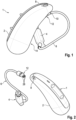
- Fig. 1 is a schematic representation of a hearing device in the form of a hearing aid, in short: "hearing aid 1".
- the hearing aid 1 is one whose housing 2 housing the electronics is to be worn behind the ear ("BTE") and which has an external loudspeaker 4.
- the loudspeaker 4 is to be worn at least partially in the ear canal of a user when worn as intended and is therefore also referred to as a "receiver in canal"("RIC").
- the loudspeaker 4 is in the intended coupling state (see Fig. 1 ) is connected to the housing 2, specifically to the electronics arranged therein - e.g. a signal processor - by means of a loudspeaker connection cable (short: "cable 6").
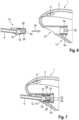
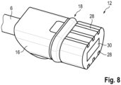
- a connector receptacle for receiving a connector 12 of the cable 6 is arranged on a surface 14 pointing downwards when the hearing aid 1 is worn as intended.
- the socket 10 is recessed into the above-mentioned surface 14. Specifically, the socket 10 is recessed in such a way that when plugged in (see Fig. 1 ) the connector 12 does not protrude or only protrudes negligibly beyond the surface 14.
- the connector 12 is shown disassembled from the socket 10. It can be seen that the connector 12 has a base body 16 which is injection-molded from a first thermoplastic material. A circumferential seal 18 made of liquid silicone rubber is injection-molded onto this base body 16. The base body 16 also has a groove 20 as part of a retaining device. A bow-shaped wire spring 22 is inserted into the socket 10 as a further part of the retaining device, which is initially tensioned radially outwards when the base body 16 is inserted and then "snaps" into the groove 20. This allows the connector 12 to be held in the socket 10 without the need for additional locking elements.
- the connector 12 and the socket 10 are designed such that the coupling is achieved by a linear insertion movement along an insertion direction 24.
- the connector 12 has a plate 26, which is preferably molded around by the base body 16 and which has a plurality of contact elements 28 on an upper side and on a lower side, here three each.
- the contact elements 28 are arranged as flat elements in the surface of the plate 26.
- Contact springs corresponding to the contact elements 28 are arranged in the socket 10 in a manner not shown in detail.
- the connector 12 and the socket 10 have complementary profiles, specifically asymmetrical ovals with a flattened (top) side. This enables clear alignment during assembly.
- the connector 12 is used to connect, for example, a permanently installed, rechargeable battery of the hearing aid 1 to a power source. Additionally (or alternatively), the connector 12 can also be used to couple a signal processor of the hearing aid 1 to a programming unit, specifically a computer on which fitting software is implemented and can run.
Landscapes
- Engineering & Computer Science (AREA)
- Health & Medical Sciences (AREA)
- General Health & Medical Sciences (AREA)
- Neurosurgery (AREA)
- Otolaryngology (AREA)
- Physics & Mathematics (AREA)
- Acoustics & Sound (AREA)
- Signal Processing (AREA)
- Computer Networks & Wireless Communication (AREA)
- Details Of Connecting Devices For Male And Female Coupling (AREA)
- Headphones And Earphones (AREA)
Claims (9)
- Dispositif auditif (1), présentant- un boîtier (2) qui s'étend le long d'un axe longitudinal, est réalisé avec une section transversale ovale et est aménagé pour incorporer des composants électriques du dispositif auditif (1),- avec un haut-parleur (4) disposé à l'extérieur du boîtier (2) dans un état de port conforme du dispositif auditif (1), et câblé avec au moins une partie des composants électriques,- avec un connecteur enfichable (12) relié au haut-parleur (4) et qui porte au moins six éléments de contact (28) pour le câblage du haut-parleur (4) avec les composants électriques correspondants, et- avec un logement de connecteur enfichable (10) pour recevoir le connecteur enfichable (12) et pour câbler les éléments de contact (28) respectifs, dans lequel le logement de connecteur enfichable (10) est disposé dans une surface (14) du boîtier (2), orientée vers une face inférieure dans un état de port conforme,caractérisé en ce que le connecteur enfichable (12) et le logement de connecteur enfichable (10) sont réalisés de telle sorte qu'une direction d'enfichage (24) s'étend d'une face frontale à une face arrière à l'état de port conforme, etle connecteur enfichable (12) présente un corps de base (16) moulé par injection d'une première matière plastique, dans lequel le corps de base (16) est disposé en biais par rapport à la surface (14) du boîtier (2), orientée vers la face inférieure, à l'état de couplage conforme et dans lequel une surface frontale du boîtier (16), orientée vers le haut-parleur (4), d'où sort un câble de liaison de haut-parleur (6), est posée en suivant la surface (14) du boîtier (2), orientée vers la face inférieure, en biais par rapport à une direction de sortie de câble du câble de liaison de haut-parleur (6).
- Dispositif auditif (1) selon la revendication 1, dans lequel le logement de connecteur enfichable (10) est encastré dans la surface (14) orientée vers la face inférieure de sorte que le connecteur enfichable (12) est invisible depuis une direction latérale à l'état d'enfichage conforme.
- Dispositif auditif (1) selon la revendication 1 ou 2, dans lequel le connecteur enfichable (12) et le logement de connecteur enfichable (10) sont configurés pour être mutuellement complémentaires et auto-alignés, ayant en particulier un profil ovale asymétrique, de préférence partiellement aplati.
- Dispositif auditif (1) selon l'une quelconque des revendications 1 à 3, dans lequel le connecteur enfichable (12) et le logement de connecteur enfichable (10) présentent respectivement une partie (20, 22) d'un dispositif de retenue pouvant être actionné automatiquement dans une direction d'enfichage (24).
- Dispositif auditif (1) selon la revendication 4, dans lequel le connecteur enfichable (12) présente une rainure (20), le logement de connecteur enfichable (10) présentant un ressort à boudin (22) qui vient en prise avec la rainure (20) à l'état de couplage conforme.
- Dispositif auditif (1) selon l'une quelconque des revendications 1 à 5, dans lequel le connecteur enfichable (12) présente un corps de base (16) moulé par injection d'une première matière plastique, et dans lequel un joint périphérique (18) est rapporté au corps de base (16) d'une deuxième matière plastique.
- Dispositif auditif (1) selon l'une quelconque des revendications 1 à 6, dans lequel le connecteur enfichable (12) présente un support de contact sous la forme d'une plaque (26) faisant saillie sur la face frontale détournée du haut-parleur (4), sur laquelle les éléments de contact (28) sont réalisés sous la forme de surfaces de contact disposées des deux côtés.
- Dispositif auditif (1) selon la revendication 7, dans lequel le logement de connecteur enfichable (10) présente des contacts à ressort correspondants pour la mise en contact de chaque surface de contact.
- Dispositif auditif (1) selon l'une quelconque des revendications 1 à 8, dans lequel le connecteur enfichable (12) présente un codage, en particulier un codage de couleur, pour indiquer le côté associé à l'oreille correspondante d'un utilisateur.
Applications Claiming Priority (1)
| Application Number | Priority Date | Filing Date | Title |
|---|---|---|---|
| DE102020205439.8A DE102020205439A1 (de) | 2020-04-29 | 2020-04-29 | Hörvorrichtung |
Publications (3)
| Publication Number | Publication Date |
|---|---|
| EP3905723A1 EP3905723A1 (fr) | 2021-11-03 |
| EP3905723B1 true EP3905723B1 (fr) | 2024-10-23 |
| EP3905723C0 EP3905723C0 (fr) | 2024-10-23 |
Family
ID=75529903
Family Applications (1)
| Application Number | Title | Priority Date | Filing Date |
|---|---|---|---|
| EP21168412.1A Active EP3905723B1 (fr) | 2020-04-29 | 2021-04-14 | Dispositif auditif |
Country Status (4)
| Country | Link |
|---|---|
| US (1) | US11729558B2 (fr) |
| EP (1) | EP3905723B1 (fr) |
| CN (1) | CN113573223A (fr) |
| DE (1) | DE102020205439A1 (fr) |
Families Citing this family (2)
| Publication number | Priority date | Publication date | Assignee | Title |
|---|---|---|---|---|
| DE202022101121U1 (de) | 2022-03-01 | 2022-03-09 | Sonova Ag | Hinter-dem-Ohr-Teil für ein Hörgerät |
| CN223219182U (zh) * | 2024-04-11 | 2025-08-12 | 深圳市韶音听力科技有限公司 | 一种可穿戴设备 |
Family Cites Families (13)
| Publication number | Priority date | Publication date | Assignee | Title |
|---|---|---|---|---|
| DE3802250C1 (fr) | 1988-01-27 | 1988-10-27 | Sonar Design & Hoertechnik Gmbh, 4400 Muenster, De | |
| US7110562B1 (en) * | 2001-08-10 | 2006-09-19 | Hear-Wear Technologies, Llc | BTE/CIC auditory device and modular connector system therefor |
| JP5518214B2 (ja) * | 2010-02-11 | 2014-06-11 | シーメンス メディカル インストゥルメンツ ピーティーイー リミテッド | プラグインコネクタを有する耳掛け形補聴器 |
| US8638965B2 (en) * | 2010-07-14 | 2014-01-28 | Starkey Laboratories, Inc. | Receiver-in-canal hearing device cable connections |
| DE102010051626B4 (de) * | 2010-11-17 | 2015-07-09 | Yamaichi Electronics Deutschland Gmbh | Hörgerät, Verbinder, Verwendung eines Verbinders und System zum Verbinden eines Hörgeräts mit einem Kabel |
| DE202013000547U1 (de) | 2013-01-18 | 2013-02-25 | Siemens Medical Instruments Pte. Ltd. | Hörinstrumentgehäuse mit Steckverbindung |
| DE102013225429A1 (de) | 2013-12-10 | 2015-06-11 | Siemens Medical Instruments Pte. Ltd. | HdO-Hörinstrument mit Gehäuse und Traghaken |
| JP6408243B2 (ja) | 2014-04-23 | 2018-10-17 | 丸山 誠二 | 耳近接スピーカ装置 |
| US10887706B2 (en) * | 2015-06-29 | 2021-01-05 | Hear-Wear Technologies LLC | Transducer modules for auditory communication devices and auditory communication devices |
| EP3226582A1 (fr) * | 2016-03-29 | 2017-10-04 | Oticon Medical A/S | Dispositif auditif comprenant des moyens de prise modulaire |
| DE102017128117A1 (de) | 2017-11-28 | 2019-05-29 | Ear-Technic GmbH | Modulares Hörgerät |
| EP4297197A3 (fr) | 2017-12-22 | 2024-03-06 | GN Hearing A/S | Connecteur d'une prothèse auditive |
| DK3537731T3 (da) | 2018-03-09 | 2021-06-21 | Oticon As | Højttalerenhed til et høreapparatssystem og et høreapparatssystem |
-
2020
- 2020-04-29 DE DE102020205439.8A patent/DE102020205439A1/de active Pending
-
2021
- 2021-04-14 EP EP21168412.1A patent/EP3905723B1/fr active Active
- 2021-04-29 CN CN202110473257.9A patent/CN113573223A/zh active Pending
- 2021-04-29 US US17/243,846 patent/US11729558B2/en active Active
Also Published As
| Publication number | Publication date |
|---|---|
| US20210345049A1 (en) | 2021-11-04 |
| US11729558B2 (en) | 2023-08-15 |
| DE102020205439A1 (de) | 2021-11-04 |
| CN113573223A (zh) | 2021-10-29 |
| EP3905723A1 (fr) | 2021-11-03 |
| EP3905723C0 (fr) | 2024-10-23 |
Similar Documents
| Publication | Publication Date | Title |
|---|---|---|
| DE68918327T3 (de) | Programmierungsschnittstelle für Hörgeräte. | |
| EP2285136B1 (fr) | Aide auditive dotée d'un écouteur échangeable | |
| EP3905723B1 (fr) | Dispositif auditif | |
| WO2020144005A1 (fr) | Pièce de connecteur enfichable pourvue d'une pièce de connecteur à relier à une pièce de boîtier | |
| WO2019105949A1 (fr) | Appareil auditif modulaire | |
| DE102007008551A1 (de) | Hörvorrichtung mit magnetisch befestigtem Batteriefach | |
| EP1993323B1 (fr) | Pièce d'oreille pour un dispositif auditif doté d'une fermeture à baïonnette | |
| EP2456235B1 (fr) | Appareil auditif, connecteur, utilisation d'un connecteur et système de connexion d'un appareil auditif à un câble | |
| DE102016209200A1 (de) | Verbindungsstück | |
| EP0087668A1 (fr) | Dispositif aide-ouie | |
| EP2091124A2 (fr) | Appareil de chargement pour un dispositif auditif doté d'un contact de chargement mobile et système d'appareil auditif correspondant | |
| DE102008024515B3 (de) | Hörhilfe und Anordnung | |
| DE102010009702A1 (de) | Hörvorrichtung mit einem Leitelement, insbesondere einem Schallschlauch | |
| EP2637426A1 (fr) | Support de batterie pour un appareil auditif | |
| WO2015036305A1 (fr) | Connecteur enfichable | |
| EP0334837B1 (fr) | Prothèse auditive avec prise d'entrée audio | |
| CH643414A5 (en) | Hearing-aid with plug device | |
| WO2009074360A1 (fr) | Dispositif d'aide auditive avec module de volet de batterie | |
| CH668154A5 (en) | Hearing aid with electroacoustic transducer - fits behind ear and has facility for plugging in range of operational mode elements | |
| EP2592849A2 (fr) | Prothèse auditive avec un compartiment pour batterie | |
| DE102021205471B3 (de) | Hörvorrichtung | |
| EP3419312B1 (fr) | Appareil auditif | |
| EP1973376B1 (fr) | Dispositif d'écoute doté d'un module de réglage du volume sonore amovible | |
| DE9306204U1 (de) | Adapter und dazu in technisch-funktionellem Zusammenhang stehendes Hörhilfegerät | |
| EP2018078A2 (fr) | Dispositif auditif doté d'un dispositif de fixation destiné à atteler un manchon audio et manchon audio correspondant |
Legal Events
| Date | Code | Title | Description |
|---|---|---|---|
| PUAI | Public reference made under article 153(3) epc to a published international application that has entered the european phase |
Free format text: ORIGINAL CODE: 0009012 |
|
| STAA | Information on the status of an ep patent application or granted ep patent |
Free format text: STATUS: THE APPLICATION HAS BEEN PUBLISHED |
|
| AK | Designated contracting states |
Kind code of ref document: A1 Designated state(s): AL AT BE BG CH CY CZ DE DK EE ES FI FR GB GR HR HU IE IS IT LI LT LU LV MC MK MT NL NO PL PT RO RS SE SI SK SM TR |
|
| B565 | Issuance of search results under rule 164(2) epc |
Effective date: 20210922 |
|
| STAA | Information on the status of an ep patent application or granted ep patent |
Free format text: STATUS: REQUEST FOR EXAMINATION WAS MADE |
|
| 17P | Request for examination filed |
Effective date: 20220218 |
|
| RBV | Designated contracting states (corrected) |
Designated state(s): AL AT BE BG CH CY CZ DE DK EE ES FI FR GB GR HR HU IE IS IT LI LT LU LV MC MK MT NL NO PL PT RO RS SE SI SK SM TR |
|
| STAA | Information on the status of an ep patent application or granted ep patent |
Free format text: STATUS: EXAMINATION IS IN PROGRESS |
|
| RIN1 | Information on inventor provided before grant (corrected) |
Inventor name: KRAL, HOLGER Inventor name: DING, LIT SONG GLEN Inventor name: ANG, THAI WEE Inventor name: BIN SHITH, MUHAMMAD SHAHID |
|
| 17Q | First examination report despatched |
Effective date: 20220804 |
|
| GRAP | Despatch of communication of intention to grant a patent |
Free format text: ORIGINAL CODE: EPIDOSNIGR1 |
|
| STAA | Information on the status of an ep patent application or granted ep patent |
Free format text: STATUS: GRANT OF PATENT IS INTENDED |
|
| INTG | Intention to grant announced |
Effective date: 20240627 |
|
| GRAS | Grant fee paid |
Free format text: ORIGINAL CODE: EPIDOSNIGR3 |
|
| GRAA | (expected) grant |
Free format text: ORIGINAL CODE: 0009210 |
|
| STAA | Information on the status of an ep patent application or granted ep patent |
Free format text: STATUS: THE PATENT HAS BEEN GRANTED |
|
| AK | Designated contracting states |
Kind code of ref document: B1 Designated state(s): AL AT BE BG CH CY CZ DE DK EE ES FI FR GB GR HR HU IE IS IT LI LT LU LV MC MK MT NL NO PL PT RO RS SE SI SK SM TR |
|
| REG | Reference to a national code |
Ref country code: GB Ref legal event code: FG4D Free format text: NOT ENGLISH |
|
| REG | Reference to a national code |
Ref country code: CH Ref legal event code: EP |
|
| REG | Reference to a national code |
Ref country code: DE Ref legal event code: R096 Ref document number: 502021005543 Country of ref document: DE |
|
| REG | Reference to a national code |
Ref country code: IE Ref legal event code: FG4D Free format text: LANGUAGE OF EP DOCUMENT: GERMAN |
|
| U01 | Request for unitary effect filed |
Effective date: 20241023 |
|
| U07 | Unitary effect registered |
Designated state(s): AT BE BG DE DK EE FI FR IT LT LU LV MT NL PT RO SE SI Effective date: 20241107 |
|
| PG25 | Lapsed in a contracting state [announced via postgrant information from national office to epo] |
Ref country code: IS Free format text: LAPSE BECAUSE OF FAILURE TO SUBMIT A TRANSLATION OF THE DESCRIPTION OR TO PAY THE FEE WITHIN THE PRESCRIBED TIME-LIMIT Effective date: 20250223 Ref country code: HR Free format text: LAPSE BECAUSE OF FAILURE TO SUBMIT A TRANSLATION OF THE DESCRIPTION OR TO PAY THE FEE WITHIN THE PRESCRIBED TIME-LIMIT Effective date: 20241023 |
|
| PG25 | Lapsed in a contracting state [announced via postgrant information from national office to epo] |
Ref country code: ES Free format text: LAPSE BECAUSE OF FAILURE TO SUBMIT A TRANSLATION OF THE DESCRIPTION OR TO PAY THE FEE WITHIN THE PRESCRIBED TIME-LIMIT Effective date: 20241023 |
|
| PG25 | Lapsed in a contracting state [announced via postgrant information from national office to epo] |
Ref country code: NO Free format text: LAPSE BECAUSE OF FAILURE TO SUBMIT A TRANSLATION OF THE DESCRIPTION OR TO PAY THE FEE WITHIN THE PRESCRIBED TIME-LIMIT Effective date: 20250123 |
|
| U20 | Renewal fee for the european patent with unitary effect paid |
Year of fee payment: 5 Effective date: 20250319 |
|
| PG25 | Lapsed in a contracting state [announced via postgrant information from national office to epo] |
Ref country code: GR Free format text: LAPSE BECAUSE OF FAILURE TO SUBMIT A TRANSLATION OF THE DESCRIPTION OR TO PAY THE FEE WITHIN THE PRESCRIBED TIME-LIMIT Effective date: 20250124 |
|
| PG25 | Lapsed in a contracting state [announced via postgrant information from national office to epo] |
Ref country code: PL Free format text: LAPSE BECAUSE OF FAILURE TO SUBMIT A TRANSLATION OF THE DESCRIPTION OR TO PAY THE FEE WITHIN THE PRESCRIBED TIME-LIMIT Effective date: 20241023 |
|
| PG25 | Lapsed in a contracting state [announced via postgrant information from national office to epo] |
Ref country code: RS Free format text: LAPSE BECAUSE OF FAILURE TO SUBMIT A TRANSLATION OF THE DESCRIPTION OR TO PAY THE FEE WITHIN THE PRESCRIBED TIME-LIMIT Effective date: 20250123 |
|
| PG25 | Lapsed in a contracting state [announced via postgrant information from national office to epo] |
Ref country code: SM Free format text: LAPSE BECAUSE OF FAILURE TO SUBMIT A TRANSLATION OF THE DESCRIPTION OR TO PAY THE FEE WITHIN THE PRESCRIBED TIME-LIMIT Effective date: 20241023 |
|
| PGFP | Annual fee paid to national office [announced via postgrant information from national office to epo] |
Ref country code: CH Payment date: 20250501 Year of fee payment: 5 |
|
| PG25 | Lapsed in a contracting state [announced via postgrant information from national office to epo] |
Ref country code: SK Free format text: LAPSE BECAUSE OF FAILURE TO SUBMIT A TRANSLATION OF THE DESCRIPTION OR TO PAY THE FEE WITHIN THE PRESCRIBED TIME-LIMIT Effective date: 20241023 |
|
| PG25 | Lapsed in a contracting state [announced via postgrant information from national office to epo] |
Ref country code: CZ Free format text: LAPSE BECAUSE OF FAILURE TO SUBMIT A TRANSLATION OF THE DESCRIPTION OR TO PAY THE FEE WITHIN THE PRESCRIBED TIME-LIMIT Effective date: 20241023 |
|
| PLBE | No opposition filed within time limit |
Free format text: ORIGINAL CODE: 0009261 |
|
| STAA | Information on the status of an ep patent application or granted ep patent |
Free format text: STATUS: NO OPPOSITION FILED WITHIN TIME LIMIT |
|
| 26N | No opposition filed |
Effective date: 20250724 |
|
| PG25 | Lapsed in a contracting state [announced via postgrant information from national office to epo] |
Ref country code: MC Free format text: LAPSE BECAUSE OF FAILURE TO SUBMIT A TRANSLATION OF THE DESCRIPTION OR TO PAY THE FEE WITHIN THE PRESCRIBED TIME-LIMIT Effective date: 20241023 |
|
| PGFP | Annual fee paid to national office [announced via postgrant information from national office to epo] |
Ref country code: GB Payment date: 20260319 Year of fee payment: 6 |
|
| PG25 | Lapsed in a contracting state [announced via postgrant information from national office to epo] |
Ref country code: IE Free format text: LAPSE BECAUSE OF NON-PAYMENT OF DUE FEES Effective date: 20250414 |
|
| U20 | Renewal fee for the european patent with unitary effect paid |
Year of fee payment: 6 Effective date: 20260319 |