EP3899307B1 - Ensemble plaquette et ressort pour étrier de frein - Google Patents
Ensemble plaquette et ressort pour étrier de frein Download PDFInfo
- Publication number
- EP3899307B1 EP3899307B1 EP19821206.0A EP19821206A EP3899307B1 EP 3899307 B1 EP3899307 B1 EP 3899307B1 EP 19821206 A EP19821206 A EP 19821206A EP 3899307 B1 EP3899307 B1 EP 3899307B1
- Authority
- EP
- European Patent Office
- Prior art keywords
- brake
- disc
- caliper
- assembly
- radial
- Prior art date
- Legal status (The legal status is an assumption and is not a legal conclusion. Google has not performed a legal analysis and makes no representation as to the accuracy of the status listed.)
- Active
Links
- 239000002783 friction material Substances 0.000 claims description 54
- 230000000284 resting effect Effects 0.000 claims description 9
- 239000000428 dust Substances 0.000 description 3
- 239000012530 fluid Substances 0.000 description 3
- 229910052782 aluminium Inorganic materials 0.000 description 2
- XAGFODPZIPBFFR-UHFFFAOYSA-N aluminium Chemical compound [Al] XAGFODPZIPBFFR-UHFFFAOYSA-N 0.000 description 2
- 230000008878 coupling Effects 0.000 description 2
- 238000010168 coupling process Methods 0.000 description 2
- 238000005859 coupling reaction Methods 0.000 description 2
- 230000002452 interceptive effect Effects 0.000 description 2
- 238000012423 maintenance Methods 0.000 description 2
- 230000002035 prolonged effect Effects 0.000 description 2
- 229910000838 Al alloy Inorganic materials 0.000 description 1
- WHXSMMKQMYFTQS-UHFFFAOYSA-N Lithium Chemical compound [Li] WHXSMMKQMYFTQS-UHFFFAOYSA-N 0.000 description 1
- 229910000639 Spring steel Inorganic materials 0.000 description 1
- 229910000831 Steel Inorganic materials 0.000 description 1
- 230000006978 adaptation Effects 0.000 description 1
- -1 aluminum and lithium Chemical compound 0.000 description 1
- 238000005266 casting Methods 0.000 description 1
- 238000001816 cooling Methods 0.000 description 1
- 230000001419 dependent effect Effects 0.000 description 1
- 210000005069 ears Anatomy 0.000 description 1
- 238000005242 forging Methods 0.000 description 1
- 239000000446 fuel Substances 0.000 description 1
- 239000012535 impurity Substances 0.000 description 1
- 229910052744 lithium Inorganic materials 0.000 description 1
- 238000003754 machining Methods 0.000 description 1
- 239000000463 material Substances 0.000 description 1
- 229910052751 metal Inorganic materials 0.000 description 1
- 239000002184 metal Substances 0.000 description 1
- 238000000034 method Methods 0.000 description 1
- 230000035515 penetration Effects 0.000 description 1
- 230000002093 peripheral effect Effects 0.000 description 1
- 230000011664 signaling Effects 0.000 description 1
- 239000010959 steel Substances 0.000 description 1
Images


Classifications
-
- F—MECHANICAL ENGINEERING; LIGHTING; HEATING; WEAPONS; BLASTING
- F16—ENGINEERING ELEMENTS AND UNITS; GENERAL MEASURES FOR PRODUCING AND MAINTAINING EFFECTIVE FUNCTIONING OF MACHINES OR INSTALLATIONS; THERMAL INSULATION IN GENERAL
- F16D—COUPLINGS FOR TRANSMITTING ROTATION; CLUTCHES; BRAKES
- F16D65/00—Parts or details
- F16D65/02—Braking members; Mounting thereof
- F16D65/04—Bands, shoes or pads; Pivots or supporting members therefor
- F16D65/092—Bands, shoes or pads; Pivots or supporting members therefor for axially-engaging brakes, e.g. disc brakes
- F16D65/095—Pivots or supporting members therefor
- F16D65/097—Resilient means interposed between pads and supporting members or other brake parts
- F16D65/0972—Resilient means interposed between pads and supporting members or other brake parts transmitting brake reaction force, e.g. elements interposed between torque support plate and pad
-
- F—MECHANICAL ENGINEERING; LIGHTING; HEATING; WEAPONS; BLASTING
- F16—ENGINEERING ELEMENTS AND UNITS; GENERAL MEASURES FOR PRODUCING AND MAINTAINING EFFECTIVE FUNCTIONING OF MACHINES OR INSTALLATIONS; THERMAL INSULATION IN GENERAL
- F16D—COUPLINGS FOR TRANSMITTING ROTATION; CLUTCHES; BRAKES
- F16D55/00—Brakes with substantially-radial braking surfaces pressed together in axial direction, e.g. disc brakes
- F16D55/02—Brakes with substantially-radial braking surfaces pressed together in axial direction, e.g. disc brakes with axially-movable discs or pads pressed against axially-located rotating members
- F16D55/22—Brakes with substantially-radial braking surfaces pressed together in axial direction, e.g. disc brakes with axially-movable discs or pads pressed against axially-located rotating members by clamping an axially-located rotating disc between movable braking members, e.g. movable brake discs or brake pads
- F16D55/224—Brakes with substantially-radial braking surfaces pressed together in axial direction, e.g. disc brakes with axially-movable discs or pads pressed against axially-located rotating members by clamping an axially-located rotating disc between movable braking members, e.g. movable brake discs or brake pads with a common actuating member for the braking members
- F16D55/225—Brakes with substantially-radial braking surfaces pressed together in axial direction, e.g. disc brakes with axially-movable discs or pads pressed against axially-located rotating members by clamping an axially-located rotating disc between movable braking members, e.g. movable brake discs or brake pads with a common actuating member for the braking members the braking members being brake pads
- F16D55/226—Brakes with substantially-radial braking surfaces pressed together in axial direction, e.g. disc brakes with axially-movable discs or pads pressed against axially-located rotating members by clamping an axially-located rotating disc between movable braking members, e.g. movable brake discs or brake pads with a common actuating member for the braking members the braking members being brake pads in which the common actuating member is moved axially, e.g. floating caliper disc brakes
-
- F—MECHANICAL ENGINEERING; LIGHTING; HEATING; WEAPONS; BLASTING
- F16—ENGINEERING ELEMENTS AND UNITS; GENERAL MEASURES FOR PRODUCING AND MAINTAINING EFFECTIVE FUNCTIONING OF MACHINES OR INSTALLATIONS; THERMAL INSULATION IN GENERAL
- F16D—COUPLINGS FOR TRANSMITTING ROTATION; CLUTCHES; BRAKES
- F16D55/00—Brakes with substantially-radial braking surfaces pressed together in axial direction, e.g. disc brakes
- F16D55/02—Brakes with substantially-radial braking surfaces pressed together in axial direction, e.g. disc brakes with axially-movable discs or pads pressed against axially-located rotating members
- F16D55/22—Brakes with substantially-radial braking surfaces pressed together in axial direction, e.g. disc brakes with axially-movable discs or pads pressed against axially-located rotating members by clamping an axially-located rotating disc between movable braking members, e.g. movable brake discs or brake pads
- F16D55/228—Brakes with substantially-radial braking surfaces pressed together in axial direction, e.g. disc brakes with axially-movable discs or pads pressed against axially-located rotating members by clamping an axially-located rotating disc between movable braking members, e.g. movable brake discs or brake pads with a separate actuating member for each side
-
- F—MECHANICAL ENGINEERING; LIGHTING; HEATING; WEAPONS; BLASTING
- F16—ENGINEERING ELEMENTS AND UNITS; GENERAL MEASURES FOR PRODUCING AND MAINTAINING EFFECTIVE FUNCTIONING OF MACHINES OR INSTALLATIONS; THERMAL INSULATION IN GENERAL
- F16D—COUPLINGS FOR TRANSMITTING ROTATION; CLUTCHES; BRAKES
- F16D65/00—Parts or details
- F16D65/02—Braking members; Mounting thereof
- F16D65/04—Bands, shoes or pads; Pivots or supporting members therefor
- F16D65/092—Bands, shoes or pads; Pivots or supporting members therefor for axially-engaging brakes, e.g. disc brakes
- F16D65/095—Pivots or supporting members therefor
- F16D65/097—Resilient means interposed between pads and supporting members or other brake parts
- F16D65/0973—Resilient means interposed between pads and supporting members or other brake parts not subjected to brake forces
- F16D65/0974—Resilient means interposed between pads and supporting members or other brake parts not subjected to brake forces acting on or in the vicinity of the pad rim in a direction substantially transverse to the brake disc axis
- F16D65/0977—Springs made from sheet metal
-
- F—MECHANICAL ENGINEERING; LIGHTING; HEATING; WEAPONS; BLASTING
- F16—ENGINEERING ELEMENTS AND UNITS; GENERAL MEASURES FOR PRODUCING AND MAINTAINING EFFECTIVE FUNCTIONING OF MACHINES OR INSTALLATIONS; THERMAL INSULATION IN GENERAL
- F16D—COUPLINGS FOR TRANSMITTING ROTATION; CLUTCHES; BRAKES
- F16D55/00—Brakes with substantially-radial braking surfaces pressed together in axial direction, e.g. disc brakes
- F16D2055/0004—Parts or details of disc brakes
- F16D2055/0016—Brake calipers
- F16D2055/002—Brake calipers assembled from a plurality of parts
-
- F—MECHANICAL ENGINEERING; LIGHTING; HEATING; WEAPONS; BLASTING
- F16—ENGINEERING ELEMENTS AND UNITS; GENERAL MEASURES FOR PRODUCING AND MAINTAINING EFFECTIVE FUNCTIONING OF MACHINES OR INSTALLATIONS; THERMAL INSULATION IN GENERAL
- F16D—COUPLINGS FOR TRANSMITTING ROTATION; CLUTCHES; BRAKES
- F16D55/00—Brakes with substantially-radial braking surfaces pressed together in axial direction, e.g. disc brakes
- F16D2055/0004—Parts or details of disc brakes
- F16D2055/0016—Brake calipers
- F16D2055/0029—Retraction devices
-
- F—MECHANICAL ENGINEERING; LIGHTING; HEATING; WEAPONS; BLASTING
- F16—ENGINEERING ELEMENTS AND UNITS; GENERAL MEASURES FOR PRODUCING AND MAINTAINING EFFECTIVE FUNCTIONING OF MACHINES OR INSTALLATIONS; THERMAL INSULATION IN GENERAL
- F16D—COUPLINGS FOR TRANSMITTING ROTATION; CLUTCHES; BRAKES
- F16D65/00—Parts or details
- F16D65/02—Braking members; Mounting thereof
- F16D2065/13—Parts or details of discs or drums
- F16D2065/134—Connection
- F16D2065/1392—Connection elements
- F16D2065/1396—Ancillary resilient elements, e.g. anti-rattle or retraction springs
-
- F—MECHANICAL ENGINEERING; LIGHTING; HEATING; WEAPONS; BLASTING
- F16—ENGINEERING ELEMENTS AND UNITS; GENERAL MEASURES FOR PRODUCING AND MAINTAINING EFFECTIVE FUNCTIONING OF MACHINES OR INSTALLATIONS; THERMAL INSULATION IN GENERAL
- F16D—COUPLINGS FOR TRANSMITTING ROTATION; CLUTCHES; BRAKES
- F16D2127/00—Auxiliary mechanisms
- F16D2127/02—Release mechanisms
-
- F—MECHANICAL ENGINEERING; LIGHTING; HEATING; WEAPONS; BLASTING
- F16—ENGINEERING ELEMENTS AND UNITS; GENERAL MEASURES FOR PRODUCING AND MAINTAINING EFFECTIVE FUNCTIONING OF MACHINES OR INSTALLATIONS; THERMAL INSULATION IN GENERAL
- F16D—COUPLINGS FOR TRANSMITTING ROTATION; CLUTCHES; BRAKES
- F16D55/00—Brakes with substantially-radial braking surfaces pressed together in axial direction, e.g. disc brakes
- F16D55/02—Brakes with substantially-radial braking surfaces pressed together in axial direction, e.g. disc brakes with axially-movable discs or pads pressed against axially-located rotating members
- F16D55/22—Brakes with substantially-radial braking surfaces pressed together in axial direction, e.g. disc brakes with axially-movable discs or pads pressed against axially-located rotating members by clamping an axially-located rotating disc between movable braking members, e.g. movable brake discs or brake pads
- F16D55/224—Brakes with substantially-radial braking surfaces pressed together in axial direction, e.g. disc brakes with axially-movable discs or pads pressed against axially-located rotating members by clamping an axially-located rotating disc between movable braking members, e.g. movable brake discs or brake pads with a common actuating member for the braking members
- F16D55/225—Brakes with substantially-radial braking surfaces pressed together in axial direction, e.g. disc brakes with axially-movable discs or pads pressed against axially-located rotating members by clamping an axially-located rotating disc between movable braking members, e.g. movable brake discs or brake pads with a common actuating member for the braking members the braking members being brake pads
- F16D55/226—Brakes with substantially-radial braking surfaces pressed together in axial direction, e.g. disc brakes with axially-movable discs or pads pressed against axially-located rotating members by clamping an axially-located rotating disc between movable braking members, e.g. movable brake discs or brake pads with a common actuating member for the braking members the braking members being brake pads in which the common actuating member is moved axially, e.g. floating caliper disc brakes
- F16D55/2265—Brakes with substantially-radial braking surfaces pressed together in axial direction, e.g. disc brakes with axially-movable discs or pads pressed against axially-located rotating members by clamping an axially-located rotating disc between movable braking members, e.g. movable brake discs or brake pads with a common actuating member for the braking members the braking members being brake pads in which the common actuating member is moved axially, e.g. floating caliper disc brakes the axial movement being guided by one or more pins engaging bores in the brake support or the brake housing
-
- F—MECHANICAL ENGINEERING; LIGHTING; HEATING; WEAPONS; BLASTING
- F16—ENGINEERING ELEMENTS AND UNITS; GENERAL MEASURES FOR PRODUCING AND MAINTAINING EFFECTIVE FUNCTIONING OF MACHINES OR INSTALLATIONS; THERMAL INSULATION IN GENERAL
- F16D—COUPLINGS FOR TRANSMITTING ROTATION; CLUTCHES; BRAKES
- F16D65/00—Parts or details
- F16D65/005—Components of axially engaging brakes not otherwise provided for
- F16D65/0068—Brake calipers
- F16D65/0075—Brake calipers assembled from a plurality of parts
Claims (10)
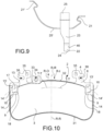
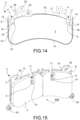
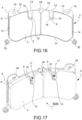
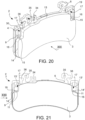
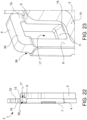
- Ensemble plaquette et ressort (1) pour un étrier de frein (10) pour un frein à disque, une direction axiale (X-X) coïncidant avec ou parallèle à l'axe de rotation d'un disque de frein dudit frein à disque, une direction radiale (R-R) orthogonale à la direction axiale (X-X), et une direction tangentielle (T-T) orthogonale à la fois à la direction axiale (X-X) et à la direction radiale (R-R) étant définies, ladite direction radiale (R-R) définissant une direction radialement vers l'intérieur (RI), dirigée vers l'axe de rotation du disque de frein, et une direction radialement vers l'extérieur (RO), opposée à la direction radialement vers l'intérieur (RI) ; ledit ensemble comprend :- au moins une plaquette de frein (2) comprenant du matériau de friction (3) et une plaque de support (4) qui supporte ledit matériau de friction (3) ;- au moins un dispositif élastique (5), adapté pour appliquer une action d'inclinaison élastique dirigée dans la direction axiale (X-X) à ladite plaquette de frein (2) pour la déplacer du disque de frein lorsque l'action de freinage cesse ;où :- ladite plaque de support (4) comprend une surface tournée vers le disque (6), associée étroitement avec ledit matériau de friction (3), et un dos de plaque (7), opposé axialement à ladite surface tournée vers le disque (6) et adapté pour faire face aux moyens de poussée (8) de l'étrier de frein (10) qui peut être associé audit ensemble (1) ;- ledit matériau de friction (3) comprend une arête radialement intérieure, adaptée pour faire face à l'axe de rotation du disque de frein, et une arête radialement extérieure (13), radialement opposée à ladite arête radialement intérieure ;- ladite arête radialement extérieure (13) du matériau de friction (3) définit le niveau de dimension radiale extérieure du matériau de friction (3) avec son extension tangentielle (13') sur ladite surface tournée vers le disque (6) de la plaque de support (4) ;- ladite surface tournée vers le disque (6) de la plaque de support (4) comprend au moins une surface libre (9) qui est exempte du contact avec le matériau de friction (3) et adaptée pour faire face à une surface de freinage du disque de frein qui peut être associé audit ensemble (1), ladite portion libre (9) étant située radialement à l'intérieur par rapport à ladite au moins une extension tangentielle (13') de l'arête radialement extérieure (13) du matériau de friction (3) ;- ladite surface libre (9) de la surface tournée vers le disque (6) de la plaque de support (4) de la plaquette de frein (2) comprend au moins une arête d'ouverture débouchante (16) qui délimite au moins partiellement une ouverture débouchante (17) dans la direction axiale (X-X) à travers ladite plaque de support (4) de la plaquette de frein (2) ;et où ledit au moins un dispositif élastique (5) présente un corps comprenant :- au moins une portion de liaison (21, 21'), adaptée pour la liaison avec le corps de l'étrier de frein (10) qui peut être associé audit ensemble (1) ; caractérisé par- au moins une portion de support (22) qui repose contre ladite arête d'ouverture débouchante (16) de la surface libre (9) de la plaque de support (4), croisant axialement ladite ouverture débouchante (17) de la plaque de support (4) pour appliquer une action d'inclinaison élastique directement dans la direction axiale (X-X) à ladite arête d'ouverture débouchante (16) de ladite ouverture débouchante (17).
- Ensemble (1) selon la revendication 1, ladite arête d'ouverture débouchante (16) étant tournée dans la direction radialement vers l'extérieur (RO) ; et/ou- ladite arête d'ouverture débouchante (16) délimitant ladite ouverture débouchante (17) dans la direction radialement vers l'intérieur (RI).
- Ensemble (1) selon la revendication 1 ou 2, ladite arête d'ouverture débouchante (16) comprenant une longueur de repos en arc (18) de sorte à permettre à la portion de repos (22) du dispositif élastique (5) de reposer dans une zone de contact minimum, coïncidant idéalement avec un seul point de contact entre le dispositif élastique (5) et l'arête d'ouverture débouchante (16) ; et/ou- ladite arête d'ouverture débouchante (16) étant associée à une glissière (11) qui s'étend entre ledit dos de plaque (7) et ladite surface libre (9) de la plaque de support (4), ladite glissière étant inclinée par rapport à la direction axiale (X-X) d'un angle d'inclinaison prédéterminé ; et/ou ledit angle d'inclinaison prédéterminé étant sensiblement égal audit angle (20) formé entre ladite portion de support (22) et ledit bras (23) du dispositif élastique (5) ; et /ou- ladite glissière (11) étant inclinée vers l'axe de rotation du disque de frein qui peut être associé audit ensemble (1) ; et/ou- ladite ouverture débouchante (17) étant entourée par un oeillet (19) ayant un côté d'oeillet radialement vers l'extérieur (30) ; et/ou ledit oeillet (19) étant axialement déporté par rapport au dos de plaque (7) et de préférence axialement déporté vers le disque de frein qui peut être associé audit ensemble (1), formant ainsi un siège de portion de repos (38) adapté pour recevoir une portion de ladite portion de support (22) du dispositif élastique (5).
- Ensemble (1) selon l'une quelconque des revendications précédentes, ledit matériau de friction (3) comprenant au moins un évidement de sorte à faire face à ladite au moins une portion libre (9) de la surface tournée vers le disque (6) de la plaque de support (4), ledit évidement de matériau de friction définissant sur ledit matériau de friction (3) au moins une surface d'arête d'évidement (15) tournée dans la direction radialement vers l'extérieur (RO) et située à une hauteur radiale la plus intérieure par rapport à ladite extension tangentielle (13') de l'arête radialement extérieure (13) du matériau de friction (3) ; et/ou- ladite ouverture débouchante (17) ouvrant audit évidement de matériau de friction (3) ; et/ou- ladite surface libre (9) de la plaque de support (4) comprenant une surface de marge d'ouverture qui entoure au moins partiellement ladite arête d'ouverture débouchante (16), et de préférence entoure ladite arête d'ouverture débouchante (16) dans la direction radialement vers l'intérieur (RI).
- Ensemble (1) selon l'une quelconque des revendications précédentes, ledit au moins un dispositif élastique (5) comprenant un corps comportant en outre au moins un bras (23) qui s'étend, de préférence dans la direction radiale (R-R), entre ladite portion de support (22) et ladite portion de liaison (21, 21') du corps du dispositif élastique (5) ; et/ou- ledit au moins un bras (23) s'étendant sur au moins une portion de celui-ci en regard et/ou en contact avec ledit dos de plaque (7) de la plaque de support (6) de la plaquette de frein (2) ; et/ou- ledit au moins un bras (23) du dispositif élastique (5) se terminant par une extrémité libre (24) définissant ladite portion de support (22) ; et/ou- ladite extrémité libre (24) définissant ladite portion de support (22) faisant saillie au moins axialement dudit bras (23) ; et/ou- ladite extrémité libre (24) faisant saillie dans la direction axiale (X-X) dudit bras (23), formant ainsi un angle (20) avec ledit bras (23) ;- ledit angle (20) étant supérieur à 90°, de préférence ledit angle (20) étant entre 120° et 180°, de préférence ledit angle (20) étant sensiblement égal à 135°.
- Ensemble (1) selon l'une quelconque des revendications précédentes, ladite ouverture débouchante (17) étant un trou débouchant entouré par une périphérie fermée ;
ou
ladite ouverture débouchante (17) étant une fente débouchante entourée par une périphérie ouverte, et de préférence ladite périphérie ouverte de l'ouverture débouchante (17) ouvrant dans la direction radialement vers l'extérieur (RO). - Ensemble (1) selon l'une quelconque des revendications précédentes, une bande de piston de dimension radiale (27) définie par la dimension radiale de l'empreinte de piston étant définie sur ledit dos de plaque (7) de la plaque de support (4) de la plaquette de frein (2) ;- ladite empreinte de piston définissant un niveau de piston radial extérieur (28) coïncidant sensiblement avec l'extension parallèle à la direction tangentielle (T-T) sur le dos de plaque (7) de la hauteur radiale de l'empreinte de piston évaluée dans le point le plus loin de celui-ci de l'axe de rotation du disque ; et/ou- ladite empreinte de piston définit un niveau de piston radial intérieur (29) coïncidant sensiblement avec l'extension parallèle à la direction tangentielle (T-T) sur le dos de plaque (7) de la hauteur radiale de l'empreinte de piston évaluée dans le point le plus proche de celui-ci par rapport à l'axe de rotation du disque ; et/ou- ladite bande de piston de dimension radiale (27) étant délimitée dans la direction radiale (R-R) par ledit niveau de piston radial extérieur (28) et ledit niveau de piston radial intérieur (29) ; et/ou ladite arête d'ouverture débouchante (16) de la surface libre (9) de la plaque de support (4) de la plaquette de frein (2), sur laquelle ladite portion de support (22) de l'élément élastique (5) repose, étant radialement à l'intérieur dudit niveau de piston radial extérieur (28), et de préférence étant incluse dans ladite bande de piston de dimension radiale (27) ; et/oule terme « empreinte de piston » signifiant une ou plusieurs zones, dans lesquelles pendant l'action de freinage, le piston (8) agit, directement ou indirectement, sur le dos de plaque (7) de la plaque de support (4) de la plaquette de frein (2).
- Ensemble (1) selon l'une quelconque des revendications précédentes, ledit dispositif élastique (5) comprenant un corps en croix, et au moins deux bras axialement opposés (23), chacun se terminant par au moins une portion de support (22) de sorte à incliner au moins deux plaquettes de frein opposées (2) dans la direction axiale (X-X) loin du disque de frein ; de sorte que ledit ensemble (1) comprenne en outre au moins une autre plaquette de frein opposée (2) de sorte à comprendre une paire de plaquettes de frein opposées (2) adaptées pour presser contre des surfaces de freinage opposées d'un disque de frein qui peut être associé audit ensemble (1) ; et/ou- ledit ensemble (1) comprenant un autre dispositif élastique séparé (5) de sorte à comprendre deux dispositifs élastiques (5) agencés tangentiellement côte à côte agissant à la fois avec leurs portions de repos (22) sur la même plaquette de frein (2) et/ou sur la même paire de plaquettes de frein opposées (2).
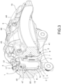
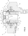
- Etrier de frein (10) pour un disque de frein comprenant un corps d'étrier (40), adapté pour être agencé chevauchant un disque de frein qui peut être associé à l'étrier de frein (10) et au moins un ensemble plaquette et ressort (1), selon l'une quelconque des revendications précédentes.
- Etrier de frein (10) selon la revendication 9, comprenant en outre des moyens de poussée (8) adaptés pour presser au moins une plaquette de frein (2) contre les surfaces de freinage avant du disque de frein qui peut être associé audit étrier de frein (10) ; et/ou
ledit corps d'étrier (40) comprenant :- une paire de portions allongées opposées (41, 42), chacune étant adaptée pour faire face, directement ou indirectement au moyen d'au moins une plaquette de frein (2), à une des surfaces de freinage opposées d'un disque de frein qui peut être associé audit étrier de frein (10) ;- au moins un pont d'étrier (43, 44) qui relie lesdites portions allongées (41, 42) les unes aux autres, étant agencé chevauchant un frein à disque associable ; et/ou- ledit au moins un pont d'étrier (43 ou 44) étant constitué au moins par trois ponts d'étrier comprenant au moins un pont central (43) et au moins une paire de ponts latéraux (44), opposés tangentiellement audit pont central (43), et lesdits au moins trois ponts d'étrier délimitant mutuellement des ouvertures de corps d'étrier radiales (45) ; et/ou- ladite au moins une portion de liaison (21, 21') d'au moins un dispositif élastique (5) de l'ensemble (1) étant couplé à au moins deux ponts d'étrier (43 et 44), et de préférence un pont central (43) et un pont latéral (44) étant agencés à l'intérieur de ladite au moins une ouverture d'étrier radiale (45).
Applications Claiming Priority (2)
| Application Number | Priority Date | Filing Date | Title |
|---|---|---|---|
| IT102018000020572A IT201800020572A1 (it) | 2018-12-20 | 2018-12-20 | Assieme di pastiglia e molla per una pinza freno |
| PCT/IB2019/060550 WO2020128710A1 (fr) | 2018-12-20 | 2019-12-09 | Ensemble plaquette et ressort pour étrier de frein |
Publications (2)
| Publication Number | Publication Date |
|---|---|
| EP3899307A1 EP3899307A1 (fr) | 2021-10-27 |
| EP3899307B1 true EP3899307B1 (fr) | 2023-06-14 |
Family
ID=66286558
Family Applications (1)
| Application Number | Title | Priority Date | Filing Date |
|---|---|---|---|
| EP19821206.0A Active EP3899307B1 (fr) | 2018-12-20 | 2019-12-09 | Ensemble plaquette et ressort pour étrier de frein |
Country Status (6)
| Country | Link |
|---|---|
| US (1) | US20220065312A1 (fr) |
| EP (1) | EP3899307B1 (fr) |
| JP (1) | JP2022514620A (fr) |
| CN (1) | CN113195923B (fr) |
| IT (1) | IT201800020572A1 (fr) |
| WO (1) | WO2020128710A1 (fr) |
Families Citing this family (7)
| Publication number | Priority date | Publication date | Assignee | Title |
|---|---|---|---|---|
| IT201800006498A1 (it) * | 2018-06-20 | 2019-12-20 | Molla per pastiglie d'attrito in una pinza per freno a disco | |
| IT202100000749A1 (it) | 2021-01-18 | 2022-07-18 | Brembo Spa | Molla a nastro ed assieme di molla a nastro e pastiglia freno |
| IT202100000743A1 (it) | 2021-01-18 | 2022-07-18 | Brembo Spa | Molla a nastro ed assieme di molla a nastro e pastiglia freno |
| IT202100025361A1 (it) | 2021-10-04 | 2023-04-04 | Brembo Spa | Molla, assieme di molla e pastiglia freno, assieme di corpo pinza |
| CN217440641U (zh) * | 2022-04-29 | 2022-09-16 | 蔚来汽车科技(安徽)有限公司 | 制动钳组件、制动器及车辆 |
| CN116900740B (zh) * | 2023-09-07 | 2023-11-14 | 烟台环球机床装备股份有限公司 | 一种可倾回转工作台 |
| CN117329244B (zh) * | 2023-12-01 | 2024-02-02 | 山西强力矿用设备制造有限公司 | 液压湿式制动集成结构 |
Family Cites Families (15)
| Publication number | Priority date | Publication date | Assignee | Title |
|---|---|---|---|---|
| US3783980A (en) * | 1971-10-13 | 1974-01-08 | Itt | Brake lining holding arrangement for spot-type disc brakes |
| IN154071B (fr) * | 1981-01-09 | 1984-09-15 | Lucas Industries Ltd | |
| DE4112947C2 (de) | 1991-04-20 | 1999-09-16 | Teves Gmbh Alfred | Bremsbacke mit Haltefeder |
| DE59409536D1 (de) | 1994-12-07 | 2000-10-26 | Continental Teves Ag & Co Ohg | Bremsbelagsatz für Schwimmsattel-Scheibenbremse |
| DE10136235A1 (de) | 2000-09-14 | 2002-07-11 | Continental Teves Ag & Co Ohg | Teilbelagsscheibenbremse sowie zugehöriger Bremsbelag mit einer Haltevorrichtung für den Bremsbelag |
| IT1395169B1 (it) * | 2009-08-13 | 2012-09-05 | Freni Brembo Spa | Molla per pinza freno di freno a disco e pinza freno dotata di tale molla |
| IT1401114B1 (it) | 2010-07-05 | 2013-07-12 | Freni Brembo Spa | Guaina di protezione di un gruppo pistone-cilindro di un freno a disco |
| JP2012189188A (ja) * | 2011-03-14 | 2012-10-04 | Akebono Brake Ind Co Ltd | ディスクブレーキ用パッドの戻し装置 |
| ITMI20111739A1 (it) | 2011-09-27 | 2013-03-28 | Freni Brembo Spa | Dispositivo di arretramento di un pistone |
| ITPD20120214A1 (it) | 2012-07-04 | 2014-01-05 | Freni Brembo Spa | Pinza di freno a disco |
| ITPD20120398A1 (it) * | 2012-12-20 | 2014-06-21 | Freni Brembo Spa | Pinza per freno a disco |
| US20140305753A1 (en) | 2013-04-12 | 2014-10-16 | Akebono Brake Corporation | Pad retraction clip |
| US10316912B2 (en) * | 2014-04-08 | 2019-06-11 | Freni Brembo S.P.A. | Disc brake pad, spring for disc brake caliper and disk brake caliper assembly |
| ITUB20155653A1 (it) * | 2015-11-17 | 2017-05-17 | Freni Brembo Spa | Pinza per freno a disco, metodo di fabbricazione di una pinza e molla per pinza |
| DE102017222639A1 (de) * | 2017-01-31 | 2018-08-02 | Continental Teves Ag & Co. Ohg | Festsattelkraftfahrzeugteilbelagscheibenbremse mit einer Stahlblechbügellüftspielfeder |
-
2018
- 2018-12-20 IT IT102018000020572A patent/IT201800020572A1/it unknown
-
2019
- 2019-12-09 JP JP2021535780A patent/JP2022514620A/ja active Pending
- 2019-12-09 EP EP19821206.0A patent/EP3899307B1/fr active Active
- 2019-12-09 US US17/415,233 patent/US20220065312A1/en active Pending
- 2019-12-09 WO PCT/IB2019/060550 patent/WO2020128710A1/fr unknown
- 2019-12-09 CN CN201980084781.8A patent/CN113195923B/zh active Active
Also Published As
| Publication number | Publication date |
|---|---|
| US20220065312A1 (en) | 2022-03-03 |
| JP2022514620A (ja) | 2022-02-14 |
| CN113195923B (zh) | 2023-09-08 |
| EP3899307A1 (fr) | 2021-10-27 |
| IT201800020572A1 (it) | 2020-06-20 |
| WO2020128710A1 (fr) | 2020-06-25 |
| CN113195923A (zh) | 2021-07-30 |
Similar Documents
| Publication | Publication Date | Title |
|---|---|---|
| EP3899307B1 (fr) | Ensemble plaquette et ressort pour étrier de frein | |
| US8567574B2 (en) | Brake caliper | |
| US5103939A (en) | Spot type disc brake | |
| EP1218645B1 (fr) | Piston pour cylindre et unite piston de frein a disque | |
| US3708043A (en) | Disc brakes | |
| US4082167A (en) | Sliding caliper-type disc brake and support structure therefore | |
| US11773932B2 (en) | Pad return spring for a disc brake caliper body | |
| US4055238A (en) | Anti-squeal device in disc brake | |
| JPH026927B2 (fr) | ||
| JP2017521616A (ja) | ブレーキ・ディスクから離れるようパッドを移動させるデバイスを備えたアッセンブリ | |
| KR100391471B1 (ko) | 자동 변속기 다판 클러치의 리턴 스프링 | |
| JPH0556411B2 (fr) | ||
| US4261443A (en) | Disc brakes for vehicles | |
| US6955247B2 (en) | Disc brake, in particular for a motor vehicle, pad for such a brake and anti-noise shim for such a pad | |
| CN110892170B (zh) | 制动卡钳与至少一个衬垫的组件 | |
| JPS6222679Y2 (fr) | ||
| US7216745B2 (en) | Mounting friction elements to disc brakes | |
| EP0027714A1 (fr) | Patins de friction pour freins à disque de véhicule et freins à disque de véhicule | |
| CA2461986A1 (fr) | Sabot de frein souple | |
| EP3717317B1 (fr) | Piston d'un étrier de freinage, étrier de freinage et -procédé de manufacture | |
| USRE32470E (en) | Disc brakes for vehicles | |
| JPS63312526A (ja) | ディスクブレーキ用スプリング | |
| CN113272571B (zh) | 用于盘式制动器和制动器卡钳的衬垫-弹簧组件 | |
| US3240296A (en) | Automatic adjusting and kickback device | |
| CN217682944U (zh) | 一种具有新型活塞结构的摩托车、自行车制动卡钳 |
Legal Events
| Date | Code | Title | Description |
|---|---|---|---|
| STAA | Information on the status of an ep patent application or granted ep patent |
Free format text: STATUS: UNKNOWN |
|
| STAA | Information on the status of an ep patent application or granted ep patent |
Free format text: STATUS: THE INTERNATIONAL PUBLICATION HAS BEEN MADE |
|
| PUAI | Public reference made under article 153(3) epc to a published international application that has entered the european phase |
Free format text: ORIGINAL CODE: 0009012 |
|
| STAA | Information on the status of an ep patent application or granted ep patent |
Free format text: STATUS: REQUEST FOR EXAMINATION WAS MADE |
|
| 17P | Request for examination filed |
Effective date: 20210616 |
|
| AK | Designated contracting states |
Kind code of ref document: A1 Designated state(s): AL AT BE BG CH CY CZ DE DK EE ES FI FR GB GR HR HU IE IS IT LI LT LU LV MC MK MT NL NO PL PT RO RS SE SI SK SM TR |
|
| DAV | Request for validation of the european patent (deleted) | ||
| DAX | Request for extension of the european patent (deleted) | ||
| GRAP | Despatch of communication of intention to grant a patent |
Free format text: ORIGINAL CODE: EPIDOSNIGR1 |
|
| STAA | Information on the status of an ep patent application or granted ep patent |
Free format text: STATUS: GRANT OF PATENT IS INTENDED |
|
| INTG | Intention to grant announced |
Effective date: 20230104 |
|
| GRAS | Grant fee paid |
Free format text: ORIGINAL CODE: EPIDOSNIGR3 |
|
| GRAA | (expected) grant |
Free format text: ORIGINAL CODE: 0009210 |
|
| STAA | Information on the status of an ep patent application or granted ep patent |
Free format text: STATUS: THE PATENT HAS BEEN GRANTED |
|
| AK | Designated contracting states |
Kind code of ref document: B1 Designated state(s): AL AT BE BG CH CY CZ DE DK EE ES FI FR GB GR HR HU IE IS IT LI LT LU LV MC MK MT NL NO PL PT RO RS SE SI SK SM TR |
|
| REG | Reference to a national code |
Ref country code: CH Ref legal event code: EP |
|
| REG | Reference to a national code |
Ref country code: DE Ref legal event code: R096 Ref document number: 602019031145 Country of ref document: DE |
|
| P01 | Opt-out of the competence of the unified patent court (upc) registered |
Effective date: 20230526 |
|
| REG | Reference to a national code |
Ref country code: AT Ref legal event code: REF Ref document number: 1579434 Country of ref document: AT Kind code of ref document: T Effective date: 20230715 |
|
| REG | Reference to a national code |
Ref country code: LT Ref legal event code: MG9D |
|
| REG | Reference to a national code |
Ref country code: NL Ref legal event code: MP Effective date: 20230614 |
|
| PG25 | Lapsed in a contracting state [announced via postgrant information from national office to epo] |
Ref country code: SE Free format text: LAPSE BECAUSE OF FAILURE TO SUBMIT A TRANSLATION OF THE DESCRIPTION OR TO PAY THE FEE WITHIN THE PRESCRIBED TIME-LIMIT Effective date: 20230614 Ref country code: NO Free format text: LAPSE BECAUSE OF FAILURE TO SUBMIT A TRANSLATION OF THE DESCRIPTION OR TO PAY THE FEE WITHIN THE PRESCRIBED TIME-LIMIT Effective date: 20230914 Ref country code: ES Free format text: LAPSE BECAUSE OF FAILURE TO SUBMIT A TRANSLATION OF THE DESCRIPTION OR TO PAY THE FEE WITHIN THE PRESCRIBED TIME-LIMIT Effective date: 20230614 |
|
| REG | Reference to a national code |
Ref country code: AT Ref legal event code: MK05 Ref document number: 1579434 Country of ref document: AT Kind code of ref document: T Effective date: 20230614 |
|
| PG25 | Lapsed in a contracting state [announced via postgrant information from national office to epo] |
Ref country code: RS Free format text: LAPSE BECAUSE OF FAILURE TO SUBMIT A TRANSLATION OF THE DESCRIPTION OR TO PAY THE FEE WITHIN THE PRESCRIBED TIME-LIMIT Effective date: 20230614 Ref country code: NL Free format text: LAPSE BECAUSE OF FAILURE TO SUBMIT A TRANSLATION OF THE DESCRIPTION OR TO PAY THE FEE WITHIN THE PRESCRIBED TIME-LIMIT Effective date: 20230614 Ref country code: LV Free format text: LAPSE BECAUSE OF FAILURE TO SUBMIT A TRANSLATION OF THE DESCRIPTION OR TO PAY THE FEE WITHIN THE PRESCRIBED TIME-LIMIT Effective date: 20230614 Ref country code: LT Free format text: LAPSE BECAUSE OF FAILURE TO SUBMIT A TRANSLATION OF THE DESCRIPTION OR TO PAY THE FEE WITHIN THE PRESCRIBED TIME-LIMIT Effective date: 20230614 Ref country code: HR Free format text: LAPSE BECAUSE OF FAILURE TO SUBMIT A TRANSLATION OF THE DESCRIPTION OR TO PAY THE FEE WITHIN THE PRESCRIBED TIME-LIMIT Effective date: 20230614 Ref country code: GR Free format text: LAPSE BECAUSE OF FAILURE TO SUBMIT A TRANSLATION OF THE DESCRIPTION OR TO PAY THE FEE WITHIN THE PRESCRIBED TIME-LIMIT Effective date: 20230915 |
|
| PG25 | Lapsed in a contracting state [announced via postgrant information from national office to epo] |
Ref country code: FI Free format text: LAPSE BECAUSE OF FAILURE TO SUBMIT A TRANSLATION OF THE DESCRIPTION OR TO PAY THE FEE WITHIN THE PRESCRIBED TIME-LIMIT Effective date: 20230614 |
|
| PG25 | Lapsed in a contracting state [announced via postgrant information from national office to epo] |
Ref country code: SK Free format text: LAPSE BECAUSE OF FAILURE TO SUBMIT A TRANSLATION OF THE DESCRIPTION OR TO PAY THE FEE WITHIN THE PRESCRIBED TIME-LIMIT Effective date: 20230614 |
|
| PGFP | Annual fee paid to national office [announced via postgrant information from national office to epo] |
Ref country code: GB Payment date: 20231220 Year of fee payment: 5 |
|
| PG25 | Lapsed in a contracting state [announced via postgrant information from national office to epo] |
Ref country code: IS Free format text: LAPSE BECAUSE OF FAILURE TO SUBMIT A TRANSLATION OF THE DESCRIPTION OR TO PAY THE FEE WITHIN THE PRESCRIBED TIME-LIMIT Effective date: 20231014 |
|
| PG25 | Lapsed in a contracting state [announced via postgrant information from national office to epo] |
Ref country code: SM Free format text: LAPSE BECAUSE OF FAILURE TO SUBMIT A TRANSLATION OF THE DESCRIPTION OR TO PAY THE FEE WITHIN THE PRESCRIBED TIME-LIMIT Effective date: 20230614 Ref country code: SK Free format text: LAPSE BECAUSE OF FAILURE TO SUBMIT A TRANSLATION OF THE DESCRIPTION OR TO PAY THE FEE WITHIN THE PRESCRIBED TIME-LIMIT Effective date: 20230614 Ref country code: RO Free format text: LAPSE BECAUSE OF FAILURE TO SUBMIT A TRANSLATION OF THE DESCRIPTION OR TO PAY THE FEE WITHIN THE PRESCRIBED TIME-LIMIT Effective date: 20230614 Ref country code: PT Free format text: LAPSE BECAUSE OF FAILURE TO SUBMIT A TRANSLATION OF THE DESCRIPTION OR TO PAY THE FEE WITHIN THE PRESCRIBED TIME-LIMIT Effective date: 20231016 Ref country code: IS Free format text: LAPSE BECAUSE OF FAILURE TO SUBMIT A TRANSLATION OF THE DESCRIPTION OR TO PAY THE FEE WITHIN THE PRESCRIBED TIME-LIMIT Effective date: 20231014 Ref country code: EE Free format text: LAPSE BECAUSE OF FAILURE TO SUBMIT A TRANSLATION OF THE DESCRIPTION OR TO PAY THE FEE WITHIN THE PRESCRIBED TIME-LIMIT Effective date: 20230614 Ref country code: CZ Free format text: LAPSE BECAUSE OF FAILURE TO SUBMIT A TRANSLATION OF THE DESCRIPTION OR TO PAY THE FEE WITHIN THE PRESCRIBED TIME-LIMIT Effective date: 20230614 Ref country code: AT Free format text: LAPSE BECAUSE OF FAILURE TO SUBMIT A TRANSLATION OF THE DESCRIPTION OR TO PAY THE FEE WITHIN THE PRESCRIBED TIME-LIMIT Effective date: 20230614 |
|
| PGFP | Annual fee paid to national office [announced via postgrant information from national office to epo] |
Ref country code: DE Payment date: 20231214 Year of fee payment: 5 |
|
| PG25 | Lapsed in a contracting state [announced via postgrant information from national office to epo] |
Ref country code: PL Free format text: LAPSE BECAUSE OF FAILURE TO SUBMIT A TRANSLATION OF THE DESCRIPTION OR TO PAY THE FEE WITHIN THE PRESCRIBED TIME-LIMIT Effective date: 20230614 |
|
| REG | Reference to a national code |
Ref country code: DE Ref legal event code: R026 Ref document number: 602019031145 Country of ref document: DE |
|
| PLBI | Opposition filed |
Free format text: ORIGINAL CODE: 0009260 |
|
| PLAX | Notice of opposition and request to file observation + time limit sent |
Free format text: ORIGINAL CODE: EPIDOSNOBS2 |
|
| 26 | Opposition filed |
Opponent name: VRI-PATENT MONITORING ASSOCIATION Effective date: 20240314 |
|
| PG25 | Lapsed in a contracting state [announced via postgrant information from national office to epo] |
Ref country code: DK Free format text: LAPSE BECAUSE OF FAILURE TO SUBMIT A TRANSLATION OF THE DESCRIPTION OR TO PAY THE FEE WITHIN THE PRESCRIBED TIME-LIMIT Effective date: 20230614 |
|
| REG | Reference to a national code |
Ref country code: CH Ref legal event code: PK Free format text: DIE PUBLIKATION VOM 27.03.2024 WURDE AM 24.04.2024 IRRTUEMLICHERWEISE ERNEUT PUBLIZIERT. LA PUBLICATION DU 27.03.2024 A ETE REPUBLIEE PAR ERREUR LE 24.04.2024. LA PUBBLICAZIONE DEL 27.03.2024 E STATA ERRONEAMENTE RIPUBBLICATA IL 24.04.2024. |
|
| PG25 | Lapsed in a contracting state [announced via postgrant information from national office to epo] |
Ref country code: SI Free format text: LAPSE BECAUSE OF FAILURE TO SUBMIT A TRANSLATION OF THE DESCRIPTION OR TO PAY THE FEE WITHIN THE PRESCRIBED TIME-LIMIT Effective date: 20230614 |