EP3899307B1 - Pad-and-spring assembly for a brake caliper - Google Patents
Pad-and-spring assembly for a brake caliper Download PDFInfo
- Publication number
- EP3899307B1 EP3899307B1 EP19821206.0A EP19821206A EP3899307B1 EP 3899307 B1 EP3899307 B1 EP 3899307B1 EP 19821206 A EP19821206 A EP 19821206A EP 3899307 B1 EP3899307 B1 EP 3899307B1
- Authority
- EP
- European Patent Office
- Prior art keywords
- brake
- disc
- caliper
- assembly
- radial
- Prior art date
- Legal status (The legal status is an assumption and is not a legal conclusion. Google has not performed a legal analysis and makes no representation as to the accuracy of the status listed.)
- Active
Links
- 239000002783 friction material Substances 0.000 claims description 54
- 230000000284 resting effect Effects 0.000 claims description 9
- 239000000428 dust Substances 0.000 description 3
- 239000012530 fluid Substances 0.000 description 3
- 229910052782 aluminium Inorganic materials 0.000 description 2
- XAGFODPZIPBFFR-UHFFFAOYSA-N aluminium Chemical compound [Al] XAGFODPZIPBFFR-UHFFFAOYSA-N 0.000 description 2
- 230000008878 coupling Effects 0.000 description 2
- 238000010168 coupling process Methods 0.000 description 2
- 238000005859 coupling reaction Methods 0.000 description 2
- 230000002452 interceptive effect Effects 0.000 description 2
- 238000012423 maintenance Methods 0.000 description 2
- 230000002035 prolonged effect Effects 0.000 description 2
- 229910000838 Al alloy Inorganic materials 0.000 description 1
- WHXSMMKQMYFTQS-UHFFFAOYSA-N Lithium Chemical compound [Li] WHXSMMKQMYFTQS-UHFFFAOYSA-N 0.000 description 1
- 229910000639 Spring steel Inorganic materials 0.000 description 1
- 229910000831 Steel Inorganic materials 0.000 description 1
- 230000006978 adaptation Effects 0.000 description 1
- -1 aluminum and lithium Chemical compound 0.000 description 1
- 238000005266 casting Methods 0.000 description 1
- 238000001816 cooling Methods 0.000 description 1
- 230000001419 dependent effect Effects 0.000 description 1
- 210000005069 ears Anatomy 0.000 description 1
- 238000005242 forging Methods 0.000 description 1
- 239000000446 fuel Substances 0.000 description 1
- 239000012535 impurity Substances 0.000 description 1
- 229910052744 lithium Inorganic materials 0.000 description 1
- 238000003754 machining Methods 0.000 description 1
- 239000000463 material Substances 0.000 description 1
- 229910052751 metal Inorganic materials 0.000 description 1
- 239000002184 metal Substances 0.000 description 1
- 238000000034 method Methods 0.000 description 1
- 230000035515 penetration Effects 0.000 description 1
- 230000002093 peripheral effect Effects 0.000 description 1
- 230000011664 signaling Effects 0.000 description 1
- 239000010959 steel Substances 0.000 description 1
Images


Classifications
-
- F—MECHANICAL ENGINEERING; LIGHTING; HEATING; WEAPONS; BLASTING
- F16—ENGINEERING ELEMENTS AND UNITS; GENERAL MEASURES FOR PRODUCING AND MAINTAINING EFFECTIVE FUNCTIONING OF MACHINES OR INSTALLATIONS; THERMAL INSULATION IN GENERAL
- F16D—COUPLINGS FOR TRANSMITTING ROTATION; CLUTCHES; BRAKES
- F16D65/00—Parts or details
- F16D65/02—Braking members; Mounting thereof
- F16D65/04—Bands, shoes or pads; Pivots or supporting members therefor
- F16D65/092—Bands, shoes or pads; Pivots or supporting members therefor for axially-engaging brakes, e.g. disc brakes
- F16D65/095—Pivots or supporting members therefor
- F16D65/097—Resilient means interposed between pads and supporting members or other brake parts
- F16D65/0972—Resilient means interposed between pads and supporting members or other brake parts transmitting brake reaction force, e.g. elements interposed between torque support plate and pad
-
- F—MECHANICAL ENGINEERING; LIGHTING; HEATING; WEAPONS; BLASTING
- F16—ENGINEERING ELEMENTS AND UNITS; GENERAL MEASURES FOR PRODUCING AND MAINTAINING EFFECTIVE FUNCTIONING OF MACHINES OR INSTALLATIONS; THERMAL INSULATION IN GENERAL
- F16D—COUPLINGS FOR TRANSMITTING ROTATION; CLUTCHES; BRAKES
- F16D55/00—Brakes with substantially-radial braking surfaces pressed together in axial direction, e.g. disc brakes
- F16D55/02—Brakes with substantially-radial braking surfaces pressed together in axial direction, e.g. disc brakes with axially-movable discs or pads pressed against axially-located rotating members
- F16D55/22—Brakes with substantially-radial braking surfaces pressed together in axial direction, e.g. disc brakes with axially-movable discs or pads pressed against axially-located rotating members by clamping an axially-located rotating disc between movable braking members, e.g. movable brake discs or brake pads
- F16D55/224—Brakes with substantially-radial braking surfaces pressed together in axial direction, e.g. disc brakes with axially-movable discs or pads pressed against axially-located rotating members by clamping an axially-located rotating disc between movable braking members, e.g. movable brake discs or brake pads with a common actuating member for the braking members
- F16D55/225—Brakes with substantially-radial braking surfaces pressed together in axial direction, e.g. disc brakes with axially-movable discs or pads pressed against axially-located rotating members by clamping an axially-located rotating disc between movable braking members, e.g. movable brake discs or brake pads with a common actuating member for the braking members the braking members being brake pads
- F16D55/226—Brakes with substantially-radial braking surfaces pressed together in axial direction, e.g. disc brakes with axially-movable discs or pads pressed against axially-located rotating members by clamping an axially-located rotating disc between movable braking members, e.g. movable brake discs or brake pads with a common actuating member for the braking members the braking members being brake pads in which the common actuating member is moved axially, e.g. floating caliper disc brakes
-
- F—MECHANICAL ENGINEERING; LIGHTING; HEATING; WEAPONS; BLASTING
- F16—ENGINEERING ELEMENTS AND UNITS; GENERAL MEASURES FOR PRODUCING AND MAINTAINING EFFECTIVE FUNCTIONING OF MACHINES OR INSTALLATIONS; THERMAL INSULATION IN GENERAL
- F16D—COUPLINGS FOR TRANSMITTING ROTATION; CLUTCHES; BRAKES
- F16D55/00—Brakes with substantially-radial braking surfaces pressed together in axial direction, e.g. disc brakes
- F16D55/02—Brakes with substantially-radial braking surfaces pressed together in axial direction, e.g. disc brakes with axially-movable discs or pads pressed against axially-located rotating members
- F16D55/22—Brakes with substantially-radial braking surfaces pressed together in axial direction, e.g. disc brakes with axially-movable discs or pads pressed against axially-located rotating members by clamping an axially-located rotating disc between movable braking members, e.g. movable brake discs or brake pads
- F16D55/228—Brakes with substantially-radial braking surfaces pressed together in axial direction, e.g. disc brakes with axially-movable discs or pads pressed against axially-located rotating members by clamping an axially-located rotating disc between movable braking members, e.g. movable brake discs or brake pads with a separate actuating member for each side
-
- F—MECHANICAL ENGINEERING; LIGHTING; HEATING; WEAPONS; BLASTING
- F16—ENGINEERING ELEMENTS AND UNITS; GENERAL MEASURES FOR PRODUCING AND MAINTAINING EFFECTIVE FUNCTIONING OF MACHINES OR INSTALLATIONS; THERMAL INSULATION IN GENERAL
- F16D—COUPLINGS FOR TRANSMITTING ROTATION; CLUTCHES; BRAKES
- F16D65/00—Parts or details
- F16D65/02—Braking members; Mounting thereof
- F16D65/04—Bands, shoes or pads; Pivots or supporting members therefor
- F16D65/092—Bands, shoes or pads; Pivots or supporting members therefor for axially-engaging brakes, e.g. disc brakes
- F16D65/095—Pivots or supporting members therefor
- F16D65/097—Resilient means interposed between pads and supporting members or other brake parts
- F16D65/0973—Resilient means interposed between pads and supporting members or other brake parts not subjected to brake forces
- F16D65/0974—Resilient means interposed between pads and supporting members or other brake parts not subjected to brake forces acting on or in the vicinity of the pad rim in a direction substantially transverse to the brake disc axis
- F16D65/0977—Springs made from sheet metal
-
- F—MECHANICAL ENGINEERING; LIGHTING; HEATING; WEAPONS; BLASTING
- F16—ENGINEERING ELEMENTS AND UNITS; GENERAL MEASURES FOR PRODUCING AND MAINTAINING EFFECTIVE FUNCTIONING OF MACHINES OR INSTALLATIONS; THERMAL INSULATION IN GENERAL
- F16D—COUPLINGS FOR TRANSMITTING ROTATION; CLUTCHES; BRAKES
- F16D55/00—Brakes with substantially-radial braking surfaces pressed together in axial direction, e.g. disc brakes
- F16D2055/0004—Parts or details of disc brakes
- F16D2055/0016—Brake calipers
- F16D2055/002—Brake calipers assembled from a plurality of parts
-
- F—MECHANICAL ENGINEERING; LIGHTING; HEATING; WEAPONS; BLASTING
- F16—ENGINEERING ELEMENTS AND UNITS; GENERAL MEASURES FOR PRODUCING AND MAINTAINING EFFECTIVE FUNCTIONING OF MACHINES OR INSTALLATIONS; THERMAL INSULATION IN GENERAL
- F16D—COUPLINGS FOR TRANSMITTING ROTATION; CLUTCHES; BRAKES
- F16D55/00—Brakes with substantially-radial braking surfaces pressed together in axial direction, e.g. disc brakes
- F16D2055/0004—Parts or details of disc brakes
- F16D2055/0016—Brake calipers
- F16D2055/0029—Retraction devices
-
- F—MECHANICAL ENGINEERING; LIGHTING; HEATING; WEAPONS; BLASTING
- F16—ENGINEERING ELEMENTS AND UNITS; GENERAL MEASURES FOR PRODUCING AND MAINTAINING EFFECTIVE FUNCTIONING OF MACHINES OR INSTALLATIONS; THERMAL INSULATION IN GENERAL
- F16D—COUPLINGS FOR TRANSMITTING ROTATION; CLUTCHES; BRAKES
- F16D65/00—Parts or details
- F16D65/02—Braking members; Mounting thereof
- F16D2065/13—Parts or details of discs or drums
- F16D2065/134—Connection
- F16D2065/1392—Connection elements
- F16D2065/1396—Ancillary resilient elements, e.g. anti-rattle or retraction springs
-
- F—MECHANICAL ENGINEERING; LIGHTING; HEATING; WEAPONS; BLASTING
- F16—ENGINEERING ELEMENTS AND UNITS; GENERAL MEASURES FOR PRODUCING AND MAINTAINING EFFECTIVE FUNCTIONING OF MACHINES OR INSTALLATIONS; THERMAL INSULATION IN GENERAL
- F16D—COUPLINGS FOR TRANSMITTING ROTATION; CLUTCHES; BRAKES
- F16D2127/00—Auxiliary mechanisms
- F16D2127/02—Release mechanisms
-
- F—MECHANICAL ENGINEERING; LIGHTING; HEATING; WEAPONS; BLASTING
- F16—ENGINEERING ELEMENTS AND UNITS; GENERAL MEASURES FOR PRODUCING AND MAINTAINING EFFECTIVE FUNCTIONING OF MACHINES OR INSTALLATIONS; THERMAL INSULATION IN GENERAL
- F16D—COUPLINGS FOR TRANSMITTING ROTATION; CLUTCHES; BRAKES
- F16D55/00—Brakes with substantially-radial braking surfaces pressed together in axial direction, e.g. disc brakes
- F16D55/02—Brakes with substantially-radial braking surfaces pressed together in axial direction, e.g. disc brakes with axially-movable discs or pads pressed against axially-located rotating members
- F16D55/22—Brakes with substantially-radial braking surfaces pressed together in axial direction, e.g. disc brakes with axially-movable discs or pads pressed against axially-located rotating members by clamping an axially-located rotating disc between movable braking members, e.g. movable brake discs or brake pads
- F16D55/224—Brakes with substantially-radial braking surfaces pressed together in axial direction, e.g. disc brakes with axially-movable discs or pads pressed against axially-located rotating members by clamping an axially-located rotating disc between movable braking members, e.g. movable brake discs or brake pads with a common actuating member for the braking members
- F16D55/225—Brakes with substantially-radial braking surfaces pressed together in axial direction, e.g. disc brakes with axially-movable discs or pads pressed against axially-located rotating members by clamping an axially-located rotating disc between movable braking members, e.g. movable brake discs or brake pads with a common actuating member for the braking members the braking members being brake pads
- F16D55/226—Brakes with substantially-radial braking surfaces pressed together in axial direction, e.g. disc brakes with axially-movable discs or pads pressed against axially-located rotating members by clamping an axially-located rotating disc between movable braking members, e.g. movable brake discs or brake pads with a common actuating member for the braking members the braking members being brake pads in which the common actuating member is moved axially, e.g. floating caliper disc brakes
- F16D55/2265—Brakes with substantially-radial braking surfaces pressed together in axial direction, e.g. disc brakes with axially-movable discs or pads pressed against axially-located rotating members by clamping an axially-located rotating disc between movable braking members, e.g. movable brake discs or brake pads with a common actuating member for the braking members the braking members being brake pads in which the common actuating member is moved axially, e.g. floating caliper disc brakes the axial movement being guided by one or more pins engaging bores in the brake support or the brake housing
-
- F—MECHANICAL ENGINEERING; LIGHTING; HEATING; WEAPONS; BLASTING
- F16—ENGINEERING ELEMENTS AND UNITS; GENERAL MEASURES FOR PRODUCING AND MAINTAINING EFFECTIVE FUNCTIONING OF MACHINES OR INSTALLATIONS; THERMAL INSULATION IN GENERAL
- F16D—COUPLINGS FOR TRANSMITTING ROTATION; CLUTCHES; BRAKES
- F16D65/00—Parts or details
- F16D65/005—Components of axially engaging brakes not otherwise provided for
- F16D65/0068—Brake calipers
- F16D65/0075—Brake calipers assembled from a plurality of parts
Definitions
- the present invention relates to a pad-and-spring assembly for a brake caliper.
- the present invention relates to a brake caliper for a disc brake comprising said assembly.
- the brake caliper is generally arranged straddling the outer peripheral margin of a brake disc, adapted to rotate about a rotation axis defining an axial direction (X-X).
- a radial direction (R-R) which is substantially orthogonal to said axial direction (X-X), and a tangential (T-T) or circumferential direction (T-T), orthogonal to both said axial direction (X-X) and said radial direction (R-R) is further defined.
- DE 10 2017 222639 discloses a an example belonging to the state of the art.
- Brake pads generally comprise a pad onto which friction material is fixed, adapted to press against a facing braking surface of the braking band of the brake disc.
- the plate may comprise auditory wear indicators, sometimes embedded in the friction material, which have the function of emitting a sound, by rubbing against the brake band of the disc when the friction material has thinned axially due to prolonged use.
- the axial (X-X), radial (R-R) and tangential (T-T) or circumferential (T-T) directions are defined on a brake pad, also when it is in a configuration not installed on a brake caliper and it is, for example, associated with at least one elastic device.
- a known type of pad is the so-called pad of the type hanging on pins, which provides eyelets made in the pad plate and adapted to receive pins specifically envisaged in the body of the caliper and intended to sustain the pad, in which the braking action is transmitted from the material to the plate which surrounds said eyelets to the caliper body.
- a different type of pad is the so-called pad of the type resting on the caliper body, which is accommodated in a specific pocket obtained in the caliper body, in which the braking action is transmitted by a side of the pad plate to the caliper body when said plate side abuts against a facing abutment surface of the caliper body pocket, at the beginning of the vehicle braking action.
- the pins associated with this type of pads act as sliding axial guides, to guide the approaching movement of the pads to the disc and the distancing of the pads from the disc.
- the caliper body is made of metal, such as aluminum, or aluminum alloy, such as aluminum and lithium, or steel, and can be obtained by casting, but also by machining by chip forming techniques, as well as by forging.
- a floating portion of the caliper body has a cylinder, or cylinders, adapted to accommodate hydraulic pistons capable of applying a thrust action on the pads facing it, making it abut against the braking surface of the disc, while it slides on the bracket, or fixed portion of the caliper, and acts on the second clutch pad making it abut against the opposite brake disc surface to apply the braking action on the vehicle.
- a cylinder or cylinders is or are present on both the axially opposite sides of the caliper body adapted to accommodate pistons, preferably hydraulic pistons, capable of applying a thrust action on the brake pads to make them abut against the respective facing disc braking surfaces to apply the braking action on the vehicle.
- the pressure applied by the vehicle driver on the brake pedal applies a brake fluid pressure which through a pipe is applied to the brake fluid present in the hydraulic circuit placed inside the caliper body to reach the cylinders, where the pressure is applied onto the bottom surface of the pistons, thus forcing them to close against the brake pads, which in turn abut against the braking surfaces of the disc.
- the caliper body deforms as a function of the torque applied by the action of the pistons which make the pads abut against the braking surfaces of the disc, applied in directions which form torque arms with respect to the fixing points of the caliper body to its support. These torques deform the caliper body also in a tangential and radial direction with respect to the disc, as well as axially, causing an increase in the piston stroke and therefore an increase in the stroke of the brake system control pedal.
- piston retraction devices are provided at the interface between piston and respective cylinder and are designed to retract the piston inside its cylinder by a limited predefined amount, moving away from the respective pad when the braking control ceases.
- Such a residual braking torque is often considered undesired because it generates noise, albeit minor, caused by the friction action between pads and disc braking surfaces, an undesired wear of the pads and of the brake disc, and implies more frequent maintenance for their replacement, and a minimum fuel consumption for feeding the drive unit with the energy, even if minimum, needed to overcome this residual torque.
- document WO-2015-155708 by the Applicant shows a cross-shaped spring solution coupled on top to the bridge of the caliper body arranged straddling the disc and provided with favorably inclined portions adapted to press against radially outer portions of the brake pads to move them away from the disc.
- Such a spring exploits the same inclined portions also to push the brake pad radially by acting on the radially outer edge of the brake pad.
- Cross-shaped springs coupled to the caliper bridge of this type require to act on the radially outer edge of the brake pad, necessarily providing a localized axial thrust which may cause a misalignment of the pads with respect to the braking surfaces of the disc facing them which, in order to be compensated, generates an uneven wear of the friction material of the pads, thus limiting the service life of the brake pads.
- Solutions of springs working on side extensions which extend tangentially from the sides of the brake pad are also known, as shown for example in document US-2014-0305753 , in which the spring leaf is folded so as to couple the brake pad with one end and the body of the caliper with the opposite end, extending with the portion folded tangentially to the side of the plate.
- Such solutions require an increased dimension in the tangential direction next to the pad both to accommodate the ears of the pad and to accommodate the folded portion of the spring, necessarily requiring to reserve volumes of free space in the body of the caliper tangentially next to the pad.
- Another known type of spring shown for example in EP-0716246 and WO-92-18785 , is located on the back of the brake pad and comprises a leaf-shaped body which alternatively couples to the piston or undercut against an elongated vehicle-wheel-facing portion of the caliper body of a floating brake caliper.
- document US-2002-096404 shows a leaf-shaped spring solution adapted to be coupled in undercut manner against walls of an annular groove provided in the piston.
- Spring solutions coupled to the piston body have the advantage of providing an elastic biasing action to the brake pad applied in the back zone of the pad in which it presses the one or more pistons, and therefore offer the possibility of acting substantially on the barycenter of the brake pad.
- the need is therefore felt to provide a spring solution to eliminate or at least minimize the residual braking torque at the same time adapted to reduce the risk of misalignments between brake pad and braking surface of the disc facing it to promote an even wear of the friction material even in conditions of prolonged use.
- a pad-and-spring assembly 1 or assembly 1 for a brake caliper 10 for disc brake is provided.
- Said assembly 1 comprises at least one brake pad 2 and at least one elastic device 5.
- an axial direction X-X is defined either coinciding with or parallel to the rotation axis of the disc (not shown) of said disc brake, a radial direction R-R orthogonal to the axial direction X-X, and a tangential direction T-T, orthogonal to both the axial direction X-X and to the radial direction R-R.
- the radial direction R-R is incident to the rotation axis of the brake disc.
- Said radial direction R-R defines a radially inward direction RI, directed towards the rotation axis of the brake disc, and a radially outward direction RO, opposite to the radially inward direction RI.
- the axial X-X, radial R-R and tangential T-T directions, as well as said radially inward direction RI and said radially outward direction RE, are also defined on a brake pad 2 when it is considered not associated with the brake caliper 10, and when said brake pad 2 is considered associated with at least one elastic device 5.
- Said at least one brake pad 2 comprises friction material 3, adapted to press against an exposed braking surface of the disc brake disc to apply the braking action, and a supporting plate 4 which supports said friction material 3.
- Said at least one elastic device 5 is adapted to apply an elastic biasing action directed in axial direction X-X to said brake pad 2 to move it away from the brake disc when the braking action ceases. In this manner, it is possible to minimize the occurrence of undesired residual braking torque.
- Said supporting plate 4 comprises a surface facing the disc 6, intimately associated with said friction material 3, and a plate back 7, axially opposite to said surface facing the disc 6 and adapted to face, either directly or indirectly, thrust means 8 of the brake caliper 10 which can be associated with said assembly 1.
- said surface facing the disc 6 is partially covered with at least one layer of friction material 3.
- said thrust means 8 of the brake caliper 10 comprise at least one piston 8 of at least one cylinder-piston assembly.
- the at least one cylinder of said at least one cylinder-piston assembly associated with said piston 8 is formed entirely in the caliper body 40 of the brake caliper 10.
- Said at least one piston 8 may be actuated hydraulically and/or electromechanically.
- Said friction material 3 comprises a radially inner edge, adapted to face the rotation axis of the brake disc, and a radially outer edge 13, radially opposite to said radially inner edge.
- Said radially outer edge 13 of the friction material 3 defines the at least one outer radial dimension level of the friction material 3 with its tangential extension 13' on a plane which contains said surface facing the disc 6 of the supporting plate 4.
- said surface facing the disc 6 of the supporting plate 4 defines a lying plane which contains it, although said supporting plate 4 has discontinuities, such as through holes and/or through slots.
- the outer radial dimension level of the friction material 3 is meant defined on a plane coincident with and parallel to the surface facing the disc 6 of the plate, even though the surface facing the disc 6 has discontinuities, such as through openings 17.
- said outer radial dimension level of the friction material 3 is defined by drawing at least one tangential extension 13' parallel to the tangential direction T-T from the radially outer edge 13 of the friction material 3 evaluated in its length which is furthest from the rotation axis of the brake disc which can be associated with said assembly 1.
- the outer radial dimension level of the friction material is given by the radially outermost portion of friction material 3.
- said disc facing surface 6 of the supporting plate 4 comprises at least one free portion 9 or free surface 9, which is free from the contact with the friction material 3 and adapted to face a braking surface of the brake disc which can be associated with said assembly 1, said free portion 9 is located radially inside with respect to said at least one tangential extension 13' of the radially outer edge 13 of the friction material 3.
- said at least one free portion 9 of the surface facing the disc 6 of the supporting plate 4 of the brake pad 2 is delimited in the radially outward direction RO by said radially outer edge 13 and/or at least one of its tangential extensions 13', and preferably by the tangential extension 13' of said radially outer edge.
- said friction material 3 has at least one recess, so as to face said at least one free portion 9 of the disc facing surface 6 of the supporting plate 4, said friction material recess defining on said friction material 3 at least one recess edge surface 15 facing in radially outward direction RO and located at an innermost radial height than said tangential extension 13' of the radially outer edge of the friction material 3.
- said free surface 9 of the surface facing the disc 6 of the supporting plate 4 of brake pad 2 comprises at least one through opening edge 16 which at least partially delimits a through opening 17 in axial direction X-X through said supporting plate 4 of brake pad 2.
- said brake pad 2 comprises at least one through opening 17 which axially connects said plate back 7 with said free surface 9.
- said through opening 17 is through across said brake pad 2.
- said through opening 17 opens at said friction material recess 3.
- said free surface 9 of the supporting plate 4 comprises an opening margin surface, which at least partially surrounds said through opening edge 16, and preferably surrounds said through opening edge 16 in radially inner manner, i.e. in the radially inward direction RI. In this manner, the supporting portion 22 is prevented from interfering with the friction material 3 under operating conditions, e.g. during braking.
- said through hole 17 is a through hole surrounded by a closed periphery.
- said closed periphery of the through opening 17 is partially described on said free surface 9.
- the closed periphery of the through opening 17 crosses the tangential extension 13' of the radially outer edge 13 of the friction material 3.
- said through opening 17 is a through slot surrounded by an open periphery, and preferably said open periphery of the through opening 17 leads to a radially outward direction RO.
- said at least one elastic device 5 has a body comprising at least one connecting portion 21, 21', adapted to connect to the body of the brake caliper 10 which can be associated with said assembly 1, and at least one supporting portion 22, which rests against said opening edge 16 of the free surface 9 of the supporting plate 4 axially crossing said passing opening 17 of the supporting plate 4.
- said at least one supporting portion 22 extends at least in axial direction X-X, and preferably also in radial direction R-R, through said through opening 17 to abut against said through opening edge 16 described on the free portion 9 of the surface facing the disc 6 of the supporting plate 4 of the brake pad 2.
- said brake pad 2 is pushed by thrust means 8 to abut against an approachable braking surface of a brake disc, concurrently applying an axial thrust action against the support portion 22 of the elastic device 5, which deforms itself by charging elastically.
- the through opening edge 16 slides on said supporting portion 22 of the elastic device 5, thereby deforming it elastically in the radially outward direction RO while remaining in contact therewith.
- the spring supporting portion 22 applies said elastic biasing action to move the brake pad 2 away from the disc.
- said through opening edge 16 is facing in radially outward direction RO.
- said through opening edge 16 delimits said through opening 17 in radially inward direction RI.
- said at least one elastic device 5 has a body further comprising at least one arm 23 which extends, preferably in radial direction R-R, between said supporting portion 22 and said connecting portion 21, 21' of the body of the elastic device 5.
- said at least one arm 23 directly connects said supporting portion 22 to said connecting portion 21, 21', if it can do so, but still allows said elastic device 5 to apply a direct elastic biasing action at least in axial direction X-X between the body of the brake caliper 10 and the brake pad 2.
- said at least one arm 23 extends for at least one portion thereof either facing and/or in contact with said plate back 7 of the supporting plate 6 of the brake pad 2.
- said at least one arm 23 extends radially outwards with respect to said tangential extension 13' of the radially outer edge 13 of the friction material 3.
- the body of said elastic device 5 comprises at least one further connecting portion 25, 25', e.g. an arm, which connects said connecting portion 21, 21' to said at least one arm 23, thereby forming a preferably arch-shaped path, so as to take said connecting portion 21, 21' to an axial level comprised between the radial extensions of the braking surfaces of the brake disc associated with said assembly 1.
- said elastic device 5 comprises a cross-shaped body, and at least two axially opposite arms 23, each ending with at least one supporting portion 22, so as to bias two opposite brake pads 2 in the axial direction X-X away from the brake disc.
- said assembly 1 further comprises at least one further opposite brake pad 2 so as to comprise two opposite brake pads 2, adapted to press against opposite braking surfaces of a brake disc which can be associated with said assembly 1.
- said assembly 1 comprises a further separate elastic device 5, so as to comprise two elastic devices 5 arranged tangentially side-by-side both acting with their resting portions 22 on the same brake pad 2 and/or on the same pair of opposite brake pads 2.
- said at least one arm 23 extends in radially outward direction RO from said supporting portion 22 of the elastic device 5 between said plate back 7 and the body of the brake caliper 10 which can be associated with said assembly 1.
- said through opening edge 16 comprises an arch-shaped resting length 18, so as to allow the resting portion 22 of the elastic device 5 to rest in a minimum contact area, ideally coinciding with a single point of contact between elastic device 5 and through opening edge 16. In this manner, it is possible to apply a ready axial elastic bias on the brake pad.
- said through opening edge 16 is associated with a slide 11 which extends between said plate back 7 and said free surface 9 of the supporting plate 4.
- said slide 11 is inclined with respect to the axial direction X-X by a predefined inclination angle.
- said slide 11 is inclined towards the rotation axis of the brake disc which can be associated with said assembly 1.
- said slide 11 is inclined in the radially inward direction RI towards said opening edge 16, in other words, it is inclined in the radially inward direction RI moving along the axial direction X-X from said plate back 7 to said free surface 9 of the surface facing the disc 6 of the supporting plate 4.
- said predetermined inclination angle is substantially equal to said angle 20 formed between said supporting portion 22 and said arm 23 of the elastic device 5.
- said through opening 17 is surrounded by an eyelet 19 having a radially outward eyelet side 30.
- said eyelet 19 being axially offset with respect to the plate back 7 is preferably axially offset towards the brake disc which can be associated with said assembly 1, thus forming a resting portion seat 38 adapted to receive a portion of said support portion 22 of the elastic device 5.
- said supporting portion 22 comprises a radially inner surface 46 which goes into abutment onto said through opening edge 16, and an opposite radially outer surface 47.
- said radially outer surface 47 goes into abutment against said radially outer edge 30 of said eyelet 19.
- said at least one arm 23 of the elastic device 5 ends with a free end 24 defining said supporting portion 22.
- said free end 24 defining said supporting portion 22 at least axially protrudes from said arm 23. In this manner, it is possible for said supporting portion 22 to go into abutment against said through opening edge 16 placed radially internally with respect to said tangential extension 13' of the radially inner edge 13 of the friction material 3 without because of this interfering with the footprint of the pistons on the plate back 7 of the brake pad 2.
- footprint of the piston means one or more areas in which, during the braking action, the piston 8 acts, either directly or indirectly, on the plate back 7 of the supporting plate of brake pad 2.
- at least one footprint of piston 8 is defined axially at the area of brake pad 2 on which the thrust means 8 act during the braking action.
- a radial dimension piston band 27 defined by the radial dimension of the piston footprint is defined on said plate back 7 of the supporting plate 4 of the brake pad 2.
- said piston footprint defines an outer radial piston level 28 substantially coinciding with the extension parallel to the tangential direction T-T on the plate back 7 of the radial height of the piston footprint evaluated in the farthest point thereof from the rotation axis of the disc.
- said piston footprint defines an inner radial piston level 29 substantially coinciding with the extension parallel to the tangential direction T-T on the plate back 7 of the radial height of the piston footprint evaluated in the closest point thereof to the rotation axis of the disc.
- said radial dimension piston band 27 is delimited in radial direction R-R by said outer radial piston level 28 and said inner radial piston level 29.
- Said radial dimension piston band 27, said outer radial piston level 28 and said inner radial piston level 29 are also defined on said surface facing the disc 6 of the supporting plate 4, by means of their axial extension through the supporting plate 4.
- said through opening edge 16 of the free surface 9 of the supporting plate 4 of the brake pad 2 on which said supporting portion 22 of the elastic element 5 rests is radially inside said outer radial piston level 28, and preferably is comprised in said radial dimension piston band 27.
- said free end 24 protrudes in axial direction X-X from said arm 23, thus forming an angle 20 with said arm 23.
- said angle 20 is greater than 90°.
- said angle 20 is comprised between 120° and 180°, preferably said angle 20 is substantially equal to 135°.
- said at least one arm 23 of the elastic device 5 is made in the form of a leaf, preferably made of spring steel.
- said arm 23 and said supporting portion 22 are made in a single piece.
- said at least one connection portion 21, 21' of elastic device 5 is adapted to be coupled to a portion of the brake caliper body 2 which can be associated with said assembly 1, and preferably at least one brake caliper bridge of said brake caliper body 10.
- said supporting plate 4 of the brake pad 2 comprises a plate radially inner edge 31, adapted to face the rotation axis of an associated disc brake disc, and an opposite plate radially outer edge 32, opposite to said plate radially inner edge 31.
- said radially outer plate edge 32 which defines a radially outer plate edge portion 33 on said surface facing the disc 6 of the supporting plate 4, radially between the radially outer plate edge 13 of the friction material 3 and the radially outer plate edge 32.
- said plate radially outer edge 32 delimits at least one wear sensor seat 34 adapted to receive at least one portion of a friction material wear signaling device.
- said plate radially outer edge 33 delimits at least one damper seat 35, adapted to receive at least one portion of a device for adjusting the vibration frequency of the brake pad, such as for example, an additional mass.
- said portion of plate radially outer edge 33 delimits at least one pin seat 36 adapted to receive at least one sliding pin 37 of said brake caliper 10 adapted to guide the movement of brake pad 2 with respect to the brake caliper body 10 both during the braking action and when the braking action ceases.
- said at least one sliding pin 37 also acts as a radial constraint to a radial elastic biasing action applied by said elastic device 5.
- said supporting portion 22 of the elastic device applies on said through opening edge 16 also a direct biasing action in the radially inward direction RI.
- said direct biasing action in the radially inward direction RI is contrasted by virtue of the provision of said sliding pins 37 that cooperate with the walls of said pin seat 36.
- said friction material 3 further comprises at least one side edge 14 facing tangential direction T-T and adapted to face the brake caliper 10 associated with said assembly 1.
- said at least one side edge 14 defines the outer radial dimension level of the friction material 3 with its tangential extension 14' on said surface facing the disc 6 of the supporting plate 4.
- said extension 14' can also not be parallel to the radial direction R-R but parallel to a definable middle axis brake pad 2.
- said free surface 9 is delimited in radially outward direction RO by said outer radial dimension level and in tangential direction T-T by said outer tangential dimension of the friction material 3 and by said friction material 3.
- said free surface 9 is delimited in radially outward direction RO by said outer radial dimension level and tangentially T-T by said friction material 3.
- a disc brake 10 comprising a caliper body 40, adapted to be arranged straddling a brake disc which can be associated with the brake caliper 10 and at least one pad-and-spring assembly 1, according to any one of the preceding embodiments.
- said brake caliper 10 further comprises thrust means 8 adapted to press at least one brake pad 2 against the facing braking surfaces of the brake disc which can be associated with said brake caliper 10.
- said thrust means comprise at least one piston 8, actuated hydraulically and/or electro-mechanically, said at least one piston 8 being associated with at least one retraction device 12, or roll-back device 12, adapted to retract by a predefined entity said piston 8 with respect to the caliper body 40 when the braking command ceases.
- said retraction device 12 also acts as a knock-back device to extract, if necessary, said piston 8 from the body of the caliper 40 by a predetermined entity.
- said thrust means 8 of the brake caliper 10 define said footprint of the piston and said radial dimension piston band 27.
- Said caliper body 40 comprises a pair of opposing elongated portions 41, 42, each adapted to face, either directly or indirectly by means of at least one brake pad 2, one of the opposite braking surfaces of a brake disc which can be associated with said brake caliper 10.
- Said caliper body 40 further comprises at least one caliper bridge 43, 44, which connects said elongated portions 41, 42 together being arranged straddling an associable disc brake.
- said at least one caliper bridge 43 or 44 are at least three caliper bridges, in which said at least three caliper bridges delimit caliper body radial openings 45 between them.
- said at least three caliper bridges comprise at least one central bridge 43 and at least one pair of side bridges 44, tangentially opposite to said central bridge 43.
- said at least one connecting portion 21, 21' of at least one elastic device 5 of the assembly 1 is coupled to at least two caliper bridges 43 and 44, and preferably a central bridge 43 and a side bridge 44, being arranged inside said at least one radial caliper opening 45.
- two separate elastic devices 5 are provided placed tangentially side by side, so as to couple both to the central bridge 43 and also to couple each to one of the end bridges 44.
- said caliper body 40 is a fixed-type caliper body having opposite thrust means 8 for brake pads housed in said opposite elongated portions 41, 42.
Description
- . The present invention relates to a pad-and-spring assembly for a brake caliper.
- . Furthermore, the present invention relates to a brake caliper for a disc brake comprising said assembly.
- . In a disc brake, the brake caliper is generally arranged straddling the outer peripheral margin of a brake disc, adapted to rotate about a rotation axis defining an axial direction (X-X). In a disc brake, a radial direction (R-R), which is substantially orthogonal to said axial direction (X-X), and a tangential (T-T) or circumferential direction (T-T), orthogonal to both said axial direction (X-X) and said radial direction (R-R), is further defined.
DE 10 2017 222639 discloses a an example belonging to the state of the art. - . Brake pads generally comprise a pad onto which friction material is fixed, adapted to press against a facing braking surface of the braking band of the brake disc. The plate may comprise auditory wear indicators, sometimes embedded in the friction material, which have the function of emitting a sound, by rubbing against the brake band of the disc when the friction material has thinned axially due to prolonged use.
- . The axial (X-X), radial (R-R) and tangential (T-T) or circumferential (T-T) directions are defined on a brake pad, also when it is in a configuration not installed on a brake caliper and it is, for example, associated with at least one elastic device.
- . A known type of pad is the so-called pad of the type hanging on pins, which provides eyelets made in the pad plate and adapted to receive pins specifically envisaged in the body of the caliper and intended to sustain the pad, in which the braking action is transmitted from the material to the plate which surrounds said eyelets to the caliper body.
- . A different type of pad is the so-called pad of the type resting on the caliper body, which is accommodated in a specific pocket obtained in the caliper body, in which the braking action is transmitted by a side of the pad plate to the caliper body when said plate side abuts against a facing abutment surface of the caliper body pocket, at the beginning of the vehicle braking action. The pins associated with this type of pads act as sliding axial guides, to guide the approaching movement of the pads to the disc and the distancing of the pads from the disc.
- . Typically, the caliper body is made of metal, such as aluminum, or aluminum alloy, such as aluminum and lithium, or steel, and can be obtained by casting, but also by machining by chip forming techniques, as well as by forging.
- . In floating caliper bodies associated with fixed discs, a floating portion of the caliper body has a cylinder, or cylinders, adapted to accommodate hydraulic pistons capable of applying a thrust action on the pads facing it, making it abut against the braking surface of the disc, while it slides on the bracket, or fixed portion of the caliper, and acts on the second clutch pad making it abut against the opposite brake disc surface to apply the braking action on the vehicle.
- . In the known caliper bodies associated with fixed discs, a cylinder or cylinders is or are present on both the axially opposite sides of the caliper body adapted to accommodate pistons, preferably hydraulic pistons, capable of applying a thrust action on the brake pads to make them abut against the respective facing disc braking surfaces to apply the braking action on the vehicle.
- . The pressure applied by the vehicle driver on the brake pedal applies a brake fluid pressure which through a pipe is applied to the brake fluid present in the hydraulic circuit placed inside the caliper body to reach the cylinders, where the pressure is applied onto the bottom surface of the pistons, thus forcing them to close against the brake pads, which in turn abut against the braking surfaces of the disc.
- . The caliper body deforms as a function of the torque applied by the action of the pistons which make the pads abut against the braking surfaces of the disc, applied in directions which form torque arms with respect to the fixing points of the caliper body to its support. These torques deform the caliper body also in a tangential and radial direction with respect to the disc, as well as axially, causing an increase in the piston stroke and therefore an increase in the stroke of the brake system control pedal.
- . When the braking action ceases, the caliper body returns to its undeformed configuration, approaching the braking surfaces of the disc and at the same time the piston of the cylinder-piston assembly receives a thrust away from the disc by means of the action of piston retraction devices, usually seals integrated in the dust boot of the piston as shown in documents
US-2013-192936 andUS-2014-231190 by the Applicant. - . Typically, such piston retraction devices (known as roll-back devices) are provided at the interface between piston and respective cylinder and are designed to retract the piston inside its cylinder by a limited predefined amount, moving away from the respective pad when the braking control ceases.
- . In this situation, the approaching of the caliper body to the disc is undesired because it determines a contact, albeit minor, between brake pads and disc braking surfaces, which determines continuous minor friction and thus a braking action, also known as residual braking torque, also when the braking command ceases.
- . Such a residual braking torque is often considered undesired because it generates noise, albeit minor, caused by the friction action between pads and disc braking surfaces, an undesired wear of the pads and of the brake disc, and implies more frequent maintenance for their replacement, and a minimum fuel consumption for feeding the drive unit with the energy, even if minimum, needed to overcome this residual torque.
- . For such a reason, it is known to associate spring brake pads which, by cooperating with parts of the brake caliper body, apply a direct bias in axial direction (X-X) on the brake pads to move them away from the brake disc when the braking action ceases, making them abut against the pistons already retracted by the roll-back devices. During the step of braking, such a biasing action away from the disc is overcome by the thrust action applied by the pistons. On the other hand, during the step of releasing, i.e. when the braking action ceases, such springs apply an axial thrust (X-X) aimed at moving the pads away from the braking surfaces of the brake disc, thereby avoiding the contact between the pads and the brake disc when no braking action is required.
- . For example, document
WO-2015-155708 by the Applicant shows a cross-shaped spring solution coupled on top to the bridge of the caliper body arranged straddling the disc and provided with favorably inclined portions adapted to press against radially outer portions of the brake pads to move them away from the disc. Such a spring exploits the same inclined portions also to push the brake pad radially by acting on the radially outer edge of the brake pad. Cross-shaped springs coupled to the caliper bridge of this type require to act on the radially outer edge of the brake pad, necessarily providing a localized axial thrust which may cause a misalignment of the pads with respect to the braking surfaces of the disc facing them which, in order to be compensated, generates an uneven wear of the friction material of the pads, thus limiting the service life of the brake pads. - . Solutions of springs working on side extensions which extend tangentially from the sides of the brake pad, are also known, as shown for example in document
US-2014-0305753 , in which the spring leaf is folded so as to couple the brake pad with one end and the body of the caliper with the opposite end, extending with the portion folded tangentially to the side of the plate. Such solutions require an increased dimension in the tangential direction next to the pad both to accommodate the ears of the pad and to accommodate the folded portion of the spring, necessarily requiring to reserve volumes of free space in the body of the caliper tangentially next to the pad. - . Another known type of spring, shown for example in
EP-0716246 andWO-92-18785 US-2002-096404 shows a leaf-shaped spring solution adapted to be coupled in undercut manner against walls of an annular groove provided in the piston. - . A further spring solution which can be associated by positive coupling with the piston is shown in document
US-2015-323024 by the Applicant, which discloses a spring solution comprising a plurality of petals adapted to press, when they are inserted into a respective substantially cylindrical lightening cavity of the piston, against the axial walls of such a cavity. - . Spring solutions coupled to the piston body have the advantage of providing an elastic biasing action to the brake pad applied in the back zone of the pad in which it presses the one or more pistons, and therefore offer the possibility of acting substantially on the barycenter of the brake pad.
- . However, such known solutions are by no means free from drawbacks, because they reduce the contact area between the back of the brake pad and the facing thrust means, e.g. a piston of a cylinder-piston assembly. Furthermore, such springs coupled to the piston necessarily limit the cooling capacity of the piston and thus of the brake fluid housed in the cylinder. Furthermore, such springs can damage the dust boot which protects the cylinder-piston assembly from the penetration of dust and impurities, thus requiring frequent maintenance.
- . The need is strongly felt to provide a spring solution to move the brake pad away from the braking surface of the disc when the braking action ceases and to make it abut against the piston which is adapted to keep the pad substantially parallel to the braking surface of the brake disc and which at the same time avoids imposing permanent coupling or connections to the piston body.
- . The need is therefore felt to provide a spring solution to eliminate or at least minimize the residual braking torque at the same time adapted to reduce the risk of misalignments between brake pad and braking surface of the disc facing it to promote an even wear of the friction material even in conditions of prolonged use.
- . It is an object of the present invention to solve the drawbacks of the prior art and to provide a solution to the needs described hereto with reference to the prior art.
- . These and other objects are achieved by an assembly according to
claim 1 and by a brake caliper according toclaim 9. - . Some advantageous embodiments are the object of the dependent claims.
- . Further features and advantages of the caliper body will be apparent from the description provided below of preferred embodiments thereof, given for illustrative but not limiting purposes, with reference to the accompanying drawings, in which:
-
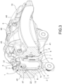
figure 1 is a radially outer axonometric view of a brake caliper, according to an embodiment; -
figure 2 is a radially outer plan view of the brake caliper infigure 1 ; -
figure 3 is an axonometric section view of the brake caliper infigures 1 and 2 , in which the plotting plane is indicated by arrows III-III infigure 2 ; -
figure 4 is a radially outer axonometric view of an elastic device, according to an embodiment; -
figure 5 is an axonometric view of a brake pad, according to an embodiment; -
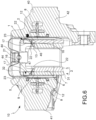
figure 6 is a section of the brake caliper shown infigures 1 and 2 , in which the plotting plane is indicated by arrows VI-VI infigure 2 ; -
figure 7 is a vertical elevation view of the elastic device infigure 4 taken from the point of view indicated by arrow VII infigure 4 ; -
figure 8 is an enlargement of the section infigure 6 in which the pad-and-spring assembly is shown by a dotted line during the braking action; -
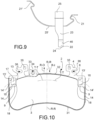
figure 9 is a vertical elevation view of the elastic device infigure 4 taken from the point of view indicated by arrow IX infigure 4 ; -
figure 10 is a vertical elevation view of the brake pad infigure 5 taken from the point of view indicated by arrow X infigure 5 ; -
figure 11 is an inner radial axonometric view of the elastic device infigure 4 ; -
figure 12 is an axonometric view of a brake pad, according to an embodiment; -
figure 13 is an axonometric section view of the brake caliper body offigures 1 and 2 taken along the plotting plane indicated by arrows III-III infigure 2 , in which an elastic device associated with the brake pad shown infigure 12 is shown; -
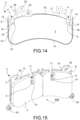
figure 14 is a vertical elevation view of the brake pad infigure 12 taken from the point of view indicated by arrow XIV infigure 12 ; -
figure 15 is an axonometric view of a brake pad, according to an embodiment; -
figure 16 is a vertical elevation view of the brake pad infigure 15 taken from the point of view indicated by arrow XVI infigure 15 ; -
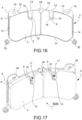
figure 17 is an axonometric view of a brake pad, according to an embodiment; -
figure 18 is a vertical elevation view of the brake pad infigure 17 taken from the point of view indicated by arrow XVIII infigure 17 ; -
figure 19 is a vertical elevation view of the back of the brake pad shown infigure 10 ; -
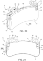
figure 20 is an axonometric view of a brake pad, according to an embodiment; -
figure 21 is a vertical elevation view of the brake pad infigure 20 taken from the point of view indicated by arrow XXI infigure 20 ; -
figure 22 is a vertical elevation view of the brake pad infigure 20 and 21 taken from the point of view indicated by arrow XXII infigure 21 ; -
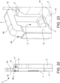
figure 23 is an axonometric view of a detail infigure 20 . - . According to a general embodiment, a pad-and-
spring assembly 1 orassembly 1 for abrake caliper 10 for disc brake is provided. - . Said
assembly 1 comprises at least onebrake pad 2 and at least oneelastic device 5. - . In a disc brake, an axial direction X-X is defined either coinciding with or parallel to the rotation axis of the disc (not shown) of said disc brake, a radial direction R-R orthogonal to the axial direction X-X, and a tangential direction T-T, orthogonal to both the axial direction X-X and to the radial direction R-R. Preferably, the radial direction R-R is incident to the rotation axis of the brake disc.
- . Said radial direction R-R defines a radially inward direction RI, directed towards the rotation axis of the brake disc, and a radially outward direction RO, opposite to the radially inward direction RI.
- . The axial X-X, radial R-R and tangential T-T directions, as well as said radially inward direction RI and said radially outward direction RE, are also defined on a
brake pad 2 when it is considered not associated with thebrake caliper 10, and when saidbrake pad 2 is considered associated with at least oneelastic device 5. - . Said at least one
brake pad 2 comprisesfriction material 3, adapted to press against an exposed braking surface of the disc brake disc to apply the braking action, and a supportingplate 4 which supports saidfriction material 3. - . Said at least one
elastic device 5 is adapted to apply an elastic biasing action directed in axial direction X-X to saidbrake pad 2 to move it away from the brake disc when the braking action ceases. In this manner, it is possible to minimize the occurrence of undesired residual braking torque. - . Said supporting
plate 4 comprises a surface facing thedisc 6, intimately associated with saidfriction material 3, and a plate back 7, axially opposite to said surface facing thedisc 6 and adapted to face, either directly or indirectly, thrust means 8 of thebrake caliper 10 which can be associated with saidassembly 1. Preferably, said surface facing thedisc 6 is partially covered with at least one layer offriction material 3. - . Preferably, said thrust means 8 of the
brake caliper 10 comprise at least onepiston 8 of at least one cylinder-piston assembly. Preferably, the at least one cylinder of said at least one cylinder-piston assembly associated with saidpiston 8 is formed entirely in thecaliper body 40 of thebrake caliper 10. Said at least onepiston 8 may be actuated hydraulically and/or electromechanically. - .
Said friction material 3 comprises a radially inner edge, adapted to face the rotation axis of the brake disc, and a radiallyouter edge 13, radially opposite to said radially inner edge. - . Said radially
outer edge 13 of thefriction material 3 defines the at least one outer radial dimension level of thefriction material 3 with its tangential extension 13' on a plane which contains said surface facing thedisc 6 of the supportingplate 4. In other words, said surface facing thedisc 6 of the supportingplate 4 defines a lying plane which contains it, although said supportingplate 4 has discontinuities, such as through holes and/or through slots. In other words, the outer radial dimension level of thefriction material 3 is meant defined on a plane coincident with and parallel to the surface facing thedisc 6 of the plate, even though the surface facing thedisc 6 has discontinuities, such as throughopenings 17. - . According to an embodiment, said outer radial dimension level of the
friction material 3 is defined by drawing at least one tangential extension 13' parallel to the tangential direction T-T from the radiallyouter edge 13 of thefriction material 3 evaluated in its length which is furthest from the rotation axis of the brake disc which can be associated with saidassembly 1. In other words, the outer radial dimension level of the friction material is given by the radially outermost portion offriction material 3. - . According to a preferred embodiment, said
disc facing surface 6 of the supportingplate 4 comprises at least onefree portion 9 orfree surface 9, which is free from the contact with thefriction material 3 and adapted to face a braking surface of the brake disc which can be associated with saidassembly 1, saidfree portion 9 is located radially inside with respect to said at least one tangential extension 13' of the radiallyouter edge 13 of thefriction material 3. In other words, said at least onefree portion 9 of the surface facing thedisc 6 of the supportingplate 4 of thebrake pad 2 is delimited in the radially outward direction RO by said radiallyouter edge 13 and/or at least one of its tangential extensions 13', and preferably by the tangential extension 13' of said radially outer edge. In other words, saidfriction material 3 has at least one recess, so as to face said at least onefree portion 9 of thedisc facing surface 6 of the supportingplate 4, said friction material recess defining on saidfriction material 3 at least onerecess edge surface 15 facing in radially outward direction RO and located at an innermost radial height than said tangential extension 13' of the radially outer edge of thefriction material 3. - . Advantageously, said
free surface 9 of the surface facing thedisc 6 of the supportingplate 4 ofbrake pad 2 comprises at least one through openingedge 16 which at least partially delimits a throughopening 17 in axial direction X-X through said supportingplate 4 ofbrake pad 2. In this manner, saidbrake pad 2 comprises at least one throughopening 17 which axially connects said plate back 7 with saidfree surface 9. Preferably, said throughopening 17 is through across saidbrake pad 2. Preferably, said throughopening 17 opens at saidfriction material recess 3. - . According to a preferred embodiment, said
free surface 9 of the supportingplate 4 comprises an opening margin surface, which at least partially surrounds said through openingedge 16, and preferably surrounds said through openingedge 16 in radially inner manner, i.e. in the radially inward direction RI. In this manner, the supportingportion 22 is prevented from interfering with thefriction material 3 under operating conditions, e.g. during braking. - . According to an embodiment, as shown for example in
figure 10 , said throughhole 17 is a through hole surrounded by a closed periphery. - . Preferably, said closed periphery of the through
opening 17 is partially described on saidfree surface 9. In other words, the closed periphery of the throughopening 17 crosses the tangential extension 13' of the radiallyouter edge 13 of thefriction material 3. - . According to an embodiment, as shown for example in
figure 13 , said throughopening 17 is a through slot surrounded by an open periphery, and preferably said open periphery of the throughopening 17 leads to a radially outward direction RO. - . With further advantage, said at least one
elastic device 5 has a body comprising at least one connectingportion 21, 21', adapted to connect to the body of thebrake caliper 10 which can be associated with saidassembly 1, and at least one supportingportion 22, which rests against said openingedge 16 of thefree surface 9 of the supportingplate 4 axially crossing said passingopening 17 of the supportingplate 4. In other words, said at least one supportingportion 22 extends at least in axial direction X-X, and preferably also in radial direction R-R, through said throughopening 17 to abut against said through openingedge 16 described on thefree portion 9 of the surface facing thedisc 6 of the supportingplate 4 of thebrake pad 2. - . In this manner, it is possible to apply an elastic biasing action on said
brake pad 2 in axial direction X-X to move thebrake pad 2 away from an associable brake disc. - . When, under operating conditions, during the braking action, said
brake pad 2 is pushed by thrust means 8 to abut against an approachable braking surface of a brake disc, concurrently applying an axial thrust action against thesupport portion 22 of theelastic device 5, which deforms itself by charging elastically. Preferably, during the braking action the through openingedge 16 slides on said supportingportion 22 of theelastic device 5, thereby deforming it elastically in the radially outward direction RO while remaining in contact therewith. When the braking control ceases, thespring supporting portion 22 applies said elastic biasing action to move thebrake pad 2 away from the disc. - . Preferably, said through opening
edge 16 is facing in radially outward direction RO. Preferably, said through openingedge 16 delimits said throughopening 17 in radially inward direction RI. - . Preferably, said at least one
elastic device 5 has a body further comprising at least onearm 23 which extends, preferably in radial direction R-R, between said supportingportion 22 and said connectingportion 21, 21' of the body of theelastic device 5. - . In this manner, it is possible to apply a direct elastic biasing action in axial direction X-X between said
caliper body 40 of thebrake caliper 10 and saidbrake pad 2 aimed at moving thebrake pad 2 away from an associable brake disc. - . Not necessarily, said at least one
arm 23 directly connects said supportingportion 22 to said connectingportion 21, 21', if it can do so, but still allows saidelastic device 5 to apply a direct elastic biasing action at least in axial direction X-X between the body of thebrake caliper 10 and thebrake pad 2. - . According to an embodiment, said at least one
arm 23 extends for at least one portion thereof either facing and/or in contact with said plate back 7 of the supportingplate 6 of thebrake pad 2. - . According to an embodiment, said at least one
arm 23 extends radially outwards with respect to said tangential extension 13' of the radiallyouter edge 13 of thefriction material 3. According to an embodiment, the body of saidelastic device 5 comprises at least one further connectingportion 25, 25', e.g. an arm, which connects said connectingportion 21, 21' to said at least onearm 23, thereby forming a preferably arch-shaped path, so as to take said connectingportion 21, 21' to an axial level comprised between the radial extensions of the braking surfaces of the brake disc associated with saidassembly 1. According to an embodiment, saidelastic device 5 comprises a cross-shaped body, and at least two axiallyopposite arms 23, each ending with at least one supportingportion 22, so as to bias twoopposite brake pads 2 in the axial direction X-X away from the brake disc. In this manner, saidassembly 1 further comprises at least one furtheropposite brake pad 2 so as to comprise twoopposite brake pads 2, adapted to press against opposite braking surfaces of a brake disc which can be associated with saidassembly 1. - . According to an embodiment, said
assembly 1 comprises a further separateelastic device 5, so as to comprise twoelastic devices 5 arranged tangentially side-by-side both acting with their restingportions 22 on thesame brake pad 2 and/or on the same pair ofopposite brake pads 2. - . According to an embodiment, said at least one
arm 23 extends in radially outward direction RO from said supportingportion 22 of theelastic device 5 between said plate back 7 and the body of thebrake caliper 10 which can be associated with saidassembly 1. - . According to a preferred embodiment, said through opening
edge 16 comprises an arch-shapedresting length 18, so as to allow the restingportion 22 of theelastic device 5 to rest in a minimum contact area, ideally coinciding with a single point of contact betweenelastic device 5 and through openingedge 16. In this manner, it is possible to apply a ready axial elastic bias on the brake pad. - . According to an embodiment, as shown for example in
figure 23 , said through openingedge 16 is associated with aslide 11 which extends between said plate back 7 and saidfree surface 9 of the supportingplate 4. Preferably, saidslide 11 is inclined with respect to the axial direction X-X by a predefined inclination angle. According to a preferred embodiment, saidslide 11 is inclined towards the rotation axis of the brake disc which can be associated with saidassembly 1. According to a preferred embodiment, saidslide 11 is inclined in the radially inward direction RI towards said openingedge 16, in other words, it is inclined in the radially inward direction RI moving along the axial direction X-X from said plate back 7 to saidfree surface 9 of the surface facing thedisc 6 of the supportingplate 4. Preferably, said predetermined inclination angle is substantially equal to saidangle 20 formed between said supportingportion 22 and saidarm 23 of theelastic device 5. - . According to an embodiment, said through
opening 17 is surrounded by aneyelet 19 having a radiallyoutward eyelet side 30. - . According to an embodiment, said
eyelet 19 being axially offset with respect to the plate back 7 is preferably axially offset towards the brake disc which can be associated with saidassembly 1, thus forming a restingportion seat 38 adapted to receive a portion of saidsupport portion 22 of theelastic device 5. - . According to an embodiment, said supporting
portion 22 comprises a radiallyinner surface 46 which goes into abutment onto said through openingedge 16, and an opposite radiallyouter surface 47. Preferably, said radiallyouter surface 47 goes into abutment against said radiallyouter edge 30 of saideyelet 19. - . According to a preferred embodiment, said at least one
arm 23 of theelastic device 5 ends with afree end 24 defining said supportingportion 22. According to a preferred embodiment, saidfree end 24 defining said supportingportion 22 at least axially protrudes from saidarm 23. In this manner, it is possible for said supportingportion 22 to go into abutment against said through openingedge 16 placed radially internally with respect to said tangential extension 13' of the radiallyinner edge 13 of thefriction material 3 without because of this interfering with the footprint of the pistons on the plate back 7 of thebrake pad 2. - . The term "footprint of the piston" means one or more areas in which, during the braking action, the
piston 8 acts, either directly or indirectly, on the plate back 7 of the supporting plate ofbrake pad 2. In other words, at least one footprint ofpiston 8 is defined axially at the area ofbrake pad 2 on which the thrust means 8 act during the braking action. - . As shown, for example in
figure 19 , preferably a radialdimension piston band 27 defined by the radial dimension of the piston footprint is defined on said plate back 7 of the supportingplate 4 of thebrake pad 2. According to an embodiment, said piston footprint defines an outerradial piston level 28 substantially coinciding with the extension parallel to the tangential direction T-T on the plate back 7 of the radial height of the piston footprint evaluated in the farthest point thereof from the rotation axis of the disc. According to an embodiment, said piston footprint defines an innerradial piston level 29 substantially coinciding with the extension parallel to the tangential direction T-T on the plate back 7 of the radial height of the piston footprint evaluated in the closest point thereof to the rotation axis of the disc. According to an embodiment, said radialdimension piston band 27 is delimited in radial direction R-R by said outerradial piston level 28 and said innerradial piston level 29. - . Said radial
dimension piston band 27, said outerradial piston level 28 and said innerradial piston level 29 are also defined on said surface facing thedisc 6 of the supportingplate 4, by means of their axial extension through the supportingplate 4. - . Preferably, said through opening
edge 16 of thefree surface 9 of the supportingplate 4 of thebrake pad 2 on which said supportingportion 22 of theelastic element 5 rests is radially inside said outerradial piston level 28, and preferably is comprised in said radialdimension piston band 27. - . According to an embodiment, said
free end 24 protrudes in axial direction X-X from saidarm 23, thus forming anangle 20 with saidarm 23. According to a preferred embodiment, saidangle 20 is greater than 90°. Preferably, saidangle 20 is comprised between 120° and 180°, preferably saidangle 20 is substantially equal to 135°. - . According to a preferred embodiment, said at least one
arm 23 of theelastic device 5 is made in the form of a leaf, preferably made of spring steel. - . Preferably, said
arm 23 and said supportingportion 22 are made in a single piece. - . According to a preferred embodiment, said at least one
connection portion 21, 21' ofelastic device 5 is adapted to be coupled to a portion of thebrake caliper body 2 which can be associated with saidassembly 1, and preferably at least one brake caliper bridge of saidbrake caliper body 10. - . According to an embodiment, said supporting
plate 4 of thebrake pad 2 comprises a plate radiallyinner edge 31, adapted to face the rotation axis of an associated disc brake disc, and an opposite plate radiallyouter edge 32, opposite to said plate radiallyinner edge 31. Preferably, said radiallyouter plate edge 32 which defines a radially outerplate edge portion 33 on said surface facing thedisc 6 of the supportingplate 4, radially between the radiallyouter plate edge 13 of thefriction material 3 and the radiallyouter plate edge 32. According to an embodiment, said plate radiallyouter edge 32 delimits at least onewear sensor seat 34 adapted to receive at least one portion of a friction material wear signaling device. According to an embodiment, said plate radiallyouter edge 33 delimits at least onedamper seat 35, adapted to receive at least one portion of a device for adjusting the vibration frequency of the brake pad, such as for example, an additional mass. - . According to an embodiment, said portion of plate radially
outer edge 33 delimits at least onepin seat 36 adapted to receive at least one slidingpin 37 of saidbrake caliper 10 adapted to guide the movement ofbrake pad 2 with respect to thebrake caliper body 10 both during the braking action and when the braking action ceases. Preferably, said at least one slidingpin 37 also acts as a radial constraint to a radial elastic biasing action applied by saidelastic device 5. According to an embodiment, said supportingportion 22 of the elastic device applies on said through openingedge 16 also a direct biasing action in the radially inward direction RI. Preferably, said direct biasing action in the radially inward direction RI is contrasted by virtue of the provision of said slidingpins 37 that cooperate with the walls of saidpin seat 36. - . According to an embodiment, said
friction material 3 further comprises at least oneside edge 14 facing tangential direction T-T and adapted to face thebrake caliper 10 associated with saidassembly 1. - . According to an embodiment, said at least one
side edge 14 defines the outer radial dimension level of thefriction material 3 with its tangential extension 14' on said surface facing thedisc 6 of the supportingplate 4. According to an embodiment, said extension 14' can also not be parallel to the radial direction R-R but parallel to a definable middleaxis brake pad 2. - . According to an embodiment, said
free surface 9 is delimited in radially outward direction RO by said outer radial dimension level and in tangential direction T-T by said outer tangential dimension of thefriction material 3 and by saidfriction material 3. - . In accordance with an embodiment, said
free surface 9 is delimited in radially outward direction RO by said outer radial dimension level and tangentially T-T by saidfriction material 3. - . According to a general embodiment, a
disc brake 10 is provided comprising acaliper body 40, adapted to be arranged straddling a brake disc which can be associated with thebrake caliper 10 and at least one pad-and-spring assembly 1, according to any one of the preceding embodiments. - . Preferably, said
brake caliper 10 further comprises thrust means 8 adapted to press at least onebrake pad 2 against the facing braking surfaces of the brake disc which can be associated with saidbrake caliper 10. Preferably, said thrust means comprise at least onepiston 8, actuated hydraulically and/or electro-mechanically, said at least onepiston 8 being associated with at least oneretraction device 12, or roll-back device 12, adapted to retract by a predefined entity saidpiston 8 with respect to thecaliper body 40 when the braking command ceases. Preferably, saidretraction device 12 also acts as a knock-back device to extract, if necessary, saidpiston 8 from the body of thecaliper 40 by a predetermined entity. - . According to an embodiment, said thrust means 8 of the
brake caliper 10 define said footprint of the piston and said radialdimension piston band 27. - .
Said caliper body 40 comprises a pair of opposingelongated portions brake pad 2, one of the opposite braking surfaces of a brake disc which can be associated with saidbrake caliper 10. - .
Said caliper body 40 further comprises at least onecaliper bridge elongated portions - . Preferably, said at least one
caliper bridge - . Preferably, said at least three caliper bridges comprise at least one
central bridge 43 and at least one pair of side bridges 44, tangentially opposite to saidcentral bridge 43. - . According to an embodiment, said at least one connecting
portion 21, 21' of at least oneelastic device 5 of theassembly 1 is coupled to at least twocaliper bridges central bridge 43 and aside bridge 44, being arranged inside said at least one radial caliper opening 45. Preferably, two separateelastic devices 5 are provided placed tangentially side by side, so as to couple both to thecentral bridge 43 and also to couple each to one of the end bridges 44. - . According to a preferred embodiment, said
caliper body 40 is a fixed-type caliper body having opposite thrust means 8 for brake pads housed in said oppositeelongated portions - . By virtue of the features described above, either mutually separately or jointly in particular embodiments, it is possible to obtain an assembly which at the same time satisfies the aforesaid mutually contrasting needs and the aforesaid desired advantages, and in particular:
- it is possible to bias the brake pad away from the disc in a balanced manner, thereby avoiding misalignments between the brake pad and the braking surfaces of the brake disc;
- it is possible to bias the brake pad away from the disc avoiding to place springs between the brake pad and the piston, in order to increase the heat exchange properties of the piston;
- it is possible to avoid encumbering volume of space between the pads with springs.
- . The person skilled in the art may make many changes and adaptations to the embodiments described above or may replace elements with others which are functionally equivalent in order to satisfy contingent needs without however departing from the scope of the appended claims.
-
- 1
- Pad-and-spring assembly or assembly
- 2
- Brake pad
- 3
- Friction material
- 4
- Supporting plate
- 5
- Elastic device
- 6
- Side facing disc of the supporting plate
- 7
- Plate back
- 8
- Thrust means or piston
- 9
- Free portion or free surface
- 10
- Brake caliper
- 11
- Slide
- 12
- Piston retraction or roll-back device
- 13
- Friction material radially outer edge
- 13'
- Tangential extension of the friction material radially outer edge
- 14
- Friction material side edge
- 14'
- Friction material side extension
- 15
- Friction material recess surface
- 16
- Through opening edge
- 17
- Through opening
- 18
- Through opening arch-shaped length
- 19
- Eyelet
- 20
- Angle
- 21, 21'
- Elastic device connecting portion
- 22
- Elastic device supporting portion
- 23
- Elastic device arm
- 24
- Elastic device free end
- 25, 25'
- Elastic device further connecting portion
- 27
- Radial dimension piston band
- 28
- Outer radial piston level on supporting plate
- 29
- Inner radial piston level on supporting plate
- 30
- Radially outer eyelet edge
- 31
- Radially inner plate edge
- 32
- Radially outer plate edge
- 33
- Radially outer plate margin
- 34
- Wear sensor seat
- 35
- Damper seat
- 36
- Pin seat
- 37
- Sliding pin
- 38
- Supporting portion seat
- 40
- Caliper body
- 41, 42
- Caliper body elongated portions
- 43
- Central caliper bridge
- 44
- Side caliper bridge
- 45
- Radial caliper opening
- 46
- Supporting portion radial inner surface
- 47
- Supporting portion radial outer surface
- X-X
- Axial direction
- R-R
- Radial direction
- T-T
- Tangential direction
- RO
- Radially outward direction
- RI
- Radially inward direction
Claims (10)
- A pad-and-spring assembly (1) for a brake caliper (10) for a disc brake, wherein an axial direction (X-X) either coinciding with or parallel to the rotation axis of a brake disc of said disc brake, a radial direction (R-R) orthogonal to the axial direction (X-X), and a tangential direction (T-T) orthogonal to both the axial direction (X-X) and the radial direction (R-R) are defined, wherein said radial direction (R-R) defines a radially inward direction (RI), directed towards the rotation axis of the brake disc, and a radially outward direction (RO), opposite to the radial inward direction (RI); said assembly comprises:- at least one brake pad (2) comprising friction material (3) and a supporting plate (4) which supports said friction material (3);- at least one elastic device (5), adapted to apply an elastic biasing action directed in axial direction (X-X) to said brake pad (2) to move it away from the brake disc when the braking action ceases;wherein:- said supporting plate (4) comprises a surface facing the disc (6), intimately associated with said friction material (3), and a plate back (7), axially opposite to said disc facing surface (6) and adapted to face thrust means (8) of the brake caliper (10) which can be associated with said assembly (1);- said friction material (3) comprises a radially inner edge, adapted to face the rotation axis of the brake disc, and a radially outer edge (13), radially opposite to said radially inner edge;- said radially outer edge (13) of the friction material (3) defines the outer radial dimension level of the friction material (3) with its tangential extension (13') on said surface facing the disc (6) of the supporting plate (4);- said disc facing surface (6) of the supporting plate (4) comprises at least one free surface (9), which is free from the contact with the friction material (3) and adapted to face a braking surface of the brake disc which can be associated with said assembly (1), wherein said free portion (9) is located radially inside with respect to said at least one tangential extension (13') of the radially outer edge (13) of the friction material (3);- said free surface (9) of the disc facing surface (6) of the supporting plate (4) of brake pad (2) comprises at least one through opening edge (16) which at least partially delimits a through opening (17) in axial direction (X-X) through said supporting plate (4) of brake pad (2);and wherein said at least one elastic device (5) has a body comprising:- at least one connecting portion (21, 21'), adapted to connect to the body of the brake caliper (10) which can be associated with said assembly (1); characterised by- at least one supporting portion (22), which rests against said through opening edge (16) of the free surface (9) of the supporting plate (4), axially crossing said through opening (17) of the supporting plate (4) to apply an elastic biasing action directly in axial direction (X-X) to said through opening edge (16) of said through opening (17).
- An assembly (1) according to claim 1, wherein said through opening edge (16) is facing in radially outward direction (RO); and/or wherein- said through opening edge (16) delimits said through opening (17) in radially inward direction (RI).
- An assembly (1) according to claim 1 or 2, wherein said through opening edge (16) comprises an arch-shaped resting length (18), so as to allow the resting portion (22) of the elastic device (5) to rest in a minimum contact area, ideally coinciding with a single point of contact between elastic device (5) and through opening edge (16); and/or wherein- said through opening edge (16) is associated with a slide (11) which extends between said plate back (7) and said free surface (9) of the supporting plate (4), said slide being inclined with respect to the axial direction (X-X) by a predetermined inclination angle; and/or wherein said predetermined inclination angle is substantially equal to said angle (20) formed between said supporting portion (22) and said arm (23) of the elastic device (5); and/or wherein- said slide (11) is inclined towards the rotation axis of the brake disc which can be associated with said assembly (1); and/or wherein- said through opening (17) is surrounded by an eyelet (19) having a radially outward eyelet side (30); and/or wherein said eyelet (19) being axially offset with respect to the plate back (7) and preferably axially offset towards the brake disc which can be associated with said assembly (1), thus forming a resting portion seat (38) adapted to receive a portion of said support portion (22) of the elastic device (5).
- An assembly (1) according to any one of the preceding claims, wherein said friction material (3) has at least one recess, so as to face said at least one free portion (9) of the disc facing surface (6) of the supporting plate (4), said friction material recess defining on said friction material (3) at least one recess edge surface (15) facing in radially outward direction (RO) and located at an innermost radial height than said tangential extension (13') of the radially outer edge (13) of the friction material (3); and/or wherein- said through opening (17) opens at said friction material recess (3); and/or wherein- said free surface (9) of the supporting plate (4) comprises an opening margin surface which at least partially surrounds said through opening edge (16), and preferably surrounds said through opening edge (16) in the radially inward direction (RI).
- An assembly (1) according to any one of the preceding claims, wherein said at least one elastic device (5) has a body further comprising at least one arm (23) which extends, preferably in radial direction (R-R), between said supporting portion (22) and said connecting portion (21, 21') of the body of the elastic device (5); and/or wherein- said at least one arm (23) extends for at least one portion thereof either facing and/or in contact with said plate back (7) of the supporting plate (6) of the brake pad (2); and/or wherein- said at least one arm (23) of the elastic device (5) ends with a free end (24) defining said supporting portion (22); and/or wherein- said free end (24) defining said supporting portion (22) at least axially protrudes from said arm (23); and/or wherein- said free end (24) protrudes in axial direction (X-X) from said arm (23), thus forming an angle (20) with said arm (23);- said angle (20) is greater than 90°, preferably said angle (20) is between 120° and 180°, preferably said angle (20) is substantially equal to 135°.
- An assembly (1) according to any one of the preceding claims, wherein said through opening (17) is a through hole surrounded by a closed periphery;
or wherein
said through opening (17) is a through slot surrounded by an open periphery, and preferably said open periphery of the through opening (17) opens in radially outward direction (RO). - An assembly (1) according to any one of the preceding claims, wherein a radial dimension piston band (27) defined by the radial dimension of the piston footprint is defined on said plate back (7) of the supporting plate (4) of the brake pad (2);- said piston footprint defines an outer radial piston level (28) substantially coinciding with the extension parallel to the tangential direction (T-T) on the plate back (7) of the radial height of the piston footprint evaluated in the farthest point thereof from the rotation axis of the disc; and/or wherein- said piston footprint defines an inner radial piston level (29) substantially coinciding with the extension parallel to the tangential direction (T-T) on the plate back (7) of the radial height of the piston footprint evaluated in the closest point thereof to the rotation axis of the disc; and/or wherein- said radial dimension piston band (27) is delimited in radial direction (R-R) by said outer radial piston level (28) and said inner radial piston level (29); and/or wherein said through opening edge (16) of the free surface (9) of the supporting plate (4) of the brake pad (2) on which said supporting portion (22) of the elastic element (5) rests is radially inside said outer radial piston level (28), and preferably is included in said radial dimension piston band (27); and/or whereinthe term "piston footprint" means one or more areas in which, during the braking action, the piston (8) acts, either directly or indirectly, on the plate back (7) of the supporting plate (4) of brake pad (2).
- An assembly (1) according to any one of the preceding claims, wherein said elastic device (5) comprises a cross-shaped body, and at least two axially opposite arms (23), each ending with at least one supporting portion (22), so as to bias at least two opposite brake pads (2) in the axial direction (X-X) away from the brake disc; so that said assembly (1) further comprises at least one further opposite brake pad (2) so as to comprise a pair of opposite brake pads (2), adapted to press against opposite braking surfaces of a brake disc which can be associated with said assembly (1); and/or wherein- said assembly (1) comprises a further separate elastic device (5), so as to comprise two elastic devices (5) arranged tangentially side-by-side both acting with their resting portions (22) on the same brake pad (2) and/or on the same pair of opposite brake pads (2).
- A brake caliper (10) for a disc brake comprising a caliper body (40), adapted to be arranged straddling a brake disc which can be associated with the brake caliper (10) and at least one pad-and-spring assembly (1), according to any one of the preceding claims.
- A brake caliper (10) according to claim 9, further comprising thrust means (8) adapted to press at least one brake pad (2) against the facing braking surfaces of the brake disc which can be associated with said brake caliper (10); and/or wherein
said caliper body (40) comprises:- a pair of opposing elongated portions (41, 42), each adapted to face, either directly or indirectly by means of at least one brake pad (2), one of the opposite braking surfaces of a brake disc which can be associated with said brake caliper (10);- at least one caliper bridge (43, 44), which connects said elongated portions (41, 42) together being arranged straddling an associable disc brake; and/or wherein- said at least one caliper bridge (43 or 44) are at least three caliper bridges comprising at least one central bridge (43) and at least one pair of side bridges (44), tangentially opposite to said central bridge (43), and wherein said at least three caliper bridges mutually delimit radial caliper body openings (45); and/orwherein- said at least one connecting portion (21, 21') of at least one elastic device (5) of the assembly (1) is coupled to at least two caliper bridges (43 and 44), and preferably a central bridge (43) and a side bridge (44), being arranged inside said at least one radial caliper opening (45).
Applications Claiming Priority (2)
| Application Number | Priority Date | Filing Date | Title |
|---|---|---|---|
| IT102018000020572A IT201800020572A1 (en) | 2018-12-20 | 2018-12-20 | ASSEMBLY OF PAD AND SPRING FOR A BRAKE CALIPER |
| PCT/IB2019/060550 WO2020128710A1 (en) | 2018-12-20 | 2019-12-09 | Pad-and-spring assembly for a brake caliper |
Publications (2)
| Publication Number | Publication Date |
|---|---|
| EP3899307A1 EP3899307A1 (en) | 2021-10-27 |
| EP3899307B1 true EP3899307B1 (en) | 2023-06-14 |
Family
ID=66286558
Family Applications (1)
| Application Number | Title | Priority Date | Filing Date |
|---|---|---|---|
| EP19821206.0A Active EP3899307B1 (en) | 2018-12-20 | 2019-12-09 | Pad-and-spring assembly for a brake caliper |
Country Status (6)
| Country | Link |
|---|---|
| US (1) | US20220065312A1 (en) |
| EP (1) | EP3899307B1 (en) |
| JP (1) | JP2022514620A (en) |
| CN (1) | CN113195923B (en) |
| IT (1) | IT201800020572A1 (en) |
| WO (1) | WO2020128710A1 (en) |
Families Citing this family (7)
| Publication number | Priority date | Publication date | Assignee | Title |
|---|---|---|---|---|
| IT201800006498A1 (en) * | 2018-06-20 | 2019-12-20 | SPRING FOR FRICTION PADS IN A DISC BRAKE CALIPER | |
| IT202100000743A1 (en) * | 2021-01-18 | 2022-07-18 | Brembo Spa | RIBBON SPRING AND SPRING RIBBON AND BRAKE PAD ASSEMBLY |
| IT202100000749A1 (en) | 2021-01-18 | 2022-07-18 | Brembo Spa | RIBBON SPRING AND SPRING RIBBON AND BRAKE PAD ASSEMBLY |
| IT202100025361A1 (en) | 2021-10-04 | 2023-04-04 | Brembo Spa | Spring, spring and brake pad assembly, caliper body assembly |
| CN217440641U (en) * | 2022-04-29 | 2022-09-16 | 蔚来汽车科技(安徽)有限公司 | Brake caliper assembly, brake and vehicle |
| CN116900740B (en) * | 2023-09-07 | 2023-11-14 | 烟台环球机床装备股份有限公司 | Tilting rotary workbench |
| CN117329244B (en) * | 2023-12-01 | 2024-02-02 | 山西强力矿用设备制造有限公司 | Hydraulic wet type braking integrated structure |
Family Cites Families (15)
| Publication number | Priority date | Publication date | Assignee | Title |
|---|---|---|---|---|
| US3783980A (en) * | 1971-10-13 | 1974-01-08 | Itt | Brake lining holding arrangement for spot-type disc brakes |
| IN154071B (en) * | 1981-01-09 | 1984-09-15 | Lucas Industries Ltd | |
| DE4112947C2 (en) | 1991-04-20 | 1999-09-16 | Teves Gmbh Alfred | Brake shoe with retaining spring |
| EP0716246B1 (en) | 1994-12-07 | 2000-09-20 | Continental Teves AG & Co. oHG | Set of brake pads for floating caliper disc brake |
| DE10136235A1 (en) | 2000-09-14 | 2002-07-11 | Continental Teves Ag & Co Ohg | Part-lined disk brake with brake lining in holder has holding device including two springs fixed to brake lining |
| IT1395169B1 (en) * | 2009-08-13 | 2012-09-05 | Freni Brembo Spa | SPRING FOR CALIPER BRAKE DISC AND BRAKE CALIPER EQUIPPED WITH SUCH SPRING |
| IT1401114B1 (en) | 2010-07-05 | 2013-07-12 | Freni Brembo Spa | GUARD OF PROTECTION OF A PISTON-CYLINDER GROUP OF A DISC BRAKE |
| JP2012189188A (en) * | 2011-03-14 | 2012-10-04 | Akebono Brake Ind Co Ltd | Apparatus for returning disk brake pad |
| ITMI20111739A1 (en) | 2011-09-27 | 2013-03-28 | Freni Brembo Spa | PISTON STOPPER DEVICE |
| ITPD20120214A1 (en) | 2012-07-04 | 2014-01-05 | Freni Brembo Spa | BRAKE CALIPER WITH DISC |
| ITPD20120398A1 (en) * | 2012-12-20 | 2014-06-21 | Freni Brembo Spa | BRAKE CALIPER WITH DISC |
| US20140305753A1 (en) | 2013-04-12 | 2014-10-16 | Akebono Brake Corporation | Pad retraction clip |
| WO2015155708A1 (en) | 2014-04-08 | 2015-10-15 | Freni Brembo S.P.A. | Disc brake pad, spring for disc brake caliper and disk brake caliper assembly |
| ITUB20155653A1 (en) * | 2015-11-17 | 2017-05-17 | Freni Brembo Spa | CALIPER FOR DISC BRAKE, METHOD OF MANUFACTURING OF A CALIPER AND SPRING FOR CALIPER |
| DE102017222639A1 (en) * | 2017-01-31 | 2018-08-02 | Continental Teves Ag & Co. Ohg | Fixed caliper motor vehicle tamper disc brake with a steel sheet bowing clearance spring |
-
2018
- 2018-12-20 IT IT102018000020572A patent/IT201800020572A1/en unknown
-
2019
- 2019-12-09 WO PCT/IB2019/060550 patent/WO2020128710A1/en unknown
- 2019-12-09 EP EP19821206.0A patent/EP3899307B1/en active Active
- 2019-12-09 JP JP2021535780A patent/JP2022514620A/en active Pending
- 2019-12-09 CN CN201980084781.8A patent/CN113195923B/en active Active
- 2019-12-09 US US17/415,233 patent/US20220065312A1/en active Pending
Also Published As
| Publication number | Publication date |
|---|---|
| WO2020128710A1 (en) | 2020-06-25 |
| US20220065312A1 (en) | 2022-03-03 |
| CN113195923B (en) | 2023-09-08 |
| IT201800020572A1 (en) | 2020-06-20 |
| JP2022514620A (en) | 2022-02-14 |
| EP3899307A1 (en) | 2021-10-27 |
| CN113195923A (en) | 2021-07-30 |
Similar Documents
| Publication | Publication Date | Title |
|---|---|---|
| EP3899307B1 (en) | Pad-and-spring assembly for a brake caliper | |
| US8567574B2 (en) | Brake caliper | |
| US5103939A (en) | Spot type disc brake | |
| US3708043A (en) | Disc brakes | |
| US4082167A (en) | Sliding caliper-type disc brake and support structure therefore | |
| JP2017521616A (en) | Assemblies with devices that move the pads away from the brake disc | |
| US11773932B2 (en) | Pad return spring for a disc brake caliper body | |
| KR100391471B1 (en) | Return spring in a multi-plate clutch for an automatic transmission | |
| JPH0556411B2 (en) | ||
| US4261443A (en) | Disc brakes for vehicles | |
| US6955247B2 (en) | Disc brake, in particular for a motor vehicle, pad for such a brake and anti-noise shim for such a pad | |
| CN110892170B (en) | Assembly of a brake caliper and at least one pad | |
| JPS6222679Y2 (en) | ||
| US7216745B2 (en) | Mounting friction elements to disc brakes | |
| EP0027714A1 (en) | Improvements in friction pad assemblies for vehicle disc brakes and in vehicle disc brakes | |
| CA2461986A1 (en) | Flexible brake shoe | |
| EP3717317B1 (en) | Brake caliper thrust device, brake caliper and manufacturing method | |
| USRE32470E (en) | Disc brakes for vehicles | |
| JPS63312526A (en) | Spring for disk brake | |
| CN113272571B (en) | Pad-spring assembly for disc brake and brake caliper | |
| US3240296A (en) | Automatic adjusting and kickback device | |
| CN217682944U (en) | Motorcycle and bicycle brake caliper with novel piston structure | |
| JP2000213571A (en) | Disc brake | |
| KR102642274B1 (en) | floating caliper disc brake | |
| RU2663772C1 (en) | Drum brake (embodiments) |
Legal Events
| Date | Code | Title | Description |
|---|---|---|---|
| STAA | Information on the status of an ep patent application or granted ep patent |
Free format text: STATUS: UNKNOWN |
|
| STAA | Information on the status of an ep patent application or granted ep patent |
Free format text: STATUS: THE INTERNATIONAL PUBLICATION HAS BEEN MADE |
|
| PUAI | Public reference made under article 153(3) epc to a published international application that has entered the european phase |
Free format text: ORIGINAL CODE: 0009012 |
|
| STAA | Information on the status of an ep patent application or granted ep patent |
Free format text: STATUS: REQUEST FOR EXAMINATION WAS MADE |
|
| 17P | Request for examination filed |
Effective date: 20210616 |
|
| AK | Designated contracting states |
Kind code of ref document: A1 Designated state(s): AL AT BE BG CH CY CZ DE DK EE ES FI FR GB GR HR HU IE IS IT LI LT LU LV MC MK MT NL NO PL PT RO RS SE SI SK SM TR |
|
| DAV | Request for validation of the european patent (deleted) | ||
| DAX | Request for extension of the european patent (deleted) | ||
| GRAP | Despatch of communication of intention to grant a patent |
Free format text: ORIGINAL CODE: EPIDOSNIGR1 |
|
| STAA | Information on the status of an ep patent application or granted ep patent |
Free format text: STATUS: GRANT OF PATENT IS INTENDED |
|
| INTG | Intention to grant announced |
Effective date: 20230104 |
|
| GRAS | Grant fee paid |
Free format text: ORIGINAL CODE: EPIDOSNIGR3 |
|
| GRAA | (expected) grant |
Free format text: ORIGINAL CODE: 0009210 |
|
| STAA | Information on the status of an ep patent application or granted ep patent |
Free format text: STATUS: THE PATENT HAS BEEN GRANTED |
|
| AK | Designated contracting states |
Kind code of ref document: B1 Designated state(s): AL AT BE BG CH CY CZ DE DK EE ES FI FR GB GR HR HU IE IS IT LI LT LU LV MC MK MT NL NO PL PT RO RS SE SI SK SM TR |
|
| REG | Reference to a national code |
Ref country code: CH Ref legal event code: EP |
|
| REG | Reference to a national code |
Ref country code: DE Ref legal event code: R096 Ref document number: 602019031145 Country of ref document: DE |
|
| P01 | Opt-out of the competence of the unified patent court (upc) registered |
Effective date: 20230526 |
|
| REG | Reference to a national code |
Ref country code: AT Ref legal event code: REF Ref document number: 1579434 Country of ref document: AT Kind code of ref document: T Effective date: 20230715 |
|
| REG | Reference to a national code |
Ref country code: LT Ref legal event code: MG9D |
|
| REG | Reference to a national code |
Ref country code: NL Ref legal event code: MP Effective date: 20230614 |
|
| PG25 | Lapsed in a contracting state [announced via postgrant information from national office to epo] |
Ref country code: SE Free format text: LAPSE BECAUSE OF FAILURE TO SUBMIT A TRANSLATION OF THE DESCRIPTION OR TO PAY THE FEE WITHIN THE PRESCRIBED TIME-LIMIT Effective date: 20230614 Ref country code: NO Free format text: LAPSE BECAUSE OF FAILURE TO SUBMIT A TRANSLATION OF THE DESCRIPTION OR TO PAY THE FEE WITHIN THE PRESCRIBED TIME-LIMIT Effective date: 20230914 Ref country code: ES Free format text: LAPSE BECAUSE OF FAILURE TO SUBMIT A TRANSLATION OF THE DESCRIPTION OR TO PAY THE FEE WITHIN THE PRESCRIBED TIME-LIMIT Effective date: 20230614 |
|
| REG | Reference to a national code |
Ref country code: AT Ref legal event code: MK05 Ref document number: 1579434 Country of ref document: AT Kind code of ref document: T Effective date: 20230614 |
|
| PG25 | Lapsed in a contracting state [announced via postgrant information from national office to epo] |
Ref country code: RS Free format text: LAPSE BECAUSE OF FAILURE TO SUBMIT A TRANSLATION OF THE DESCRIPTION OR TO PAY THE FEE WITHIN THE PRESCRIBED TIME-LIMIT Effective date: 20230614 Ref country code: NL Free format text: LAPSE BECAUSE OF FAILURE TO SUBMIT A TRANSLATION OF THE DESCRIPTION OR TO PAY THE FEE WITHIN THE PRESCRIBED TIME-LIMIT Effective date: 20230614 Ref country code: LV Free format text: LAPSE BECAUSE OF FAILURE TO SUBMIT A TRANSLATION OF THE DESCRIPTION OR TO PAY THE FEE WITHIN THE PRESCRIBED TIME-LIMIT Effective date: 20230614 Ref country code: LT Free format text: LAPSE BECAUSE OF FAILURE TO SUBMIT A TRANSLATION OF THE DESCRIPTION OR TO PAY THE FEE WITHIN THE PRESCRIBED TIME-LIMIT Effective date: 20230614 Ref country code: HR Free format text: LAPSE BECAUSE OF FAILURE TO SUBMIT A TRANSLATION OF THE DESCRIPTION OR TO PAY THE FEE WITHIN THE PRESCRIBED TIME-LIMIT Effective date: 20230614 Ref country code: GR Free format text: LAPSE BECAUSE OF FAILURE TO SUBMIT A TRANSLATION OF THE DESCRIPTION OR TO PAY THE FEE WITHIN THE PRESCRIBED TIME-LIMIT Effective date: 20230915 |
|
| PG25 | Lapsed in a contracting state [announced via postgrant information from national office to epo] |
Ref country code: FI Free format text: LAPSE BECAUSE OF FAILURE TO SUBMIT A TRANSLATION OF THE DESCRIPTION OR TO PAY THE FEE WITHIN THE PRESCRIBED TIME-LIMIT Effective date: 20230614 |
|
| PG25 | Lapsed in a contracting state [announced via postgrant information from national office to epo] |
Ref country code: SK Free format text: LAPSE BECAUSE OF FAILURE TO SUBMIT A TRANSLATION OF THE DESCRIPTION OR TO PAY THE FEE WITHIN THE PRESCRIBED TIME-LIMIT Effective date: 20230614 |
|
| PGFP | Annual fee paid to national office [announced via postgrant information from national office to epo] |
Ref country code: GB Payment date: 20231220 Year of fee payment: 5 |
|
| PG25 | Lapsed in a contracting state [announced via postgrant information from national office to epo] |
Ref country code: IS Free format text: LAPSE BECAUSE OF FAILURE TO SUBMIT A TRANSLATION OF THE DESCRIPTION OR TO PAY THE FEE WITHIN THE PRESCRIBED TIME-LIMIT Effective date: 20231014 |
|
| PG25 | Lapsed in a contracting state [announced via postgrant information from national office to epo] |
Ref country code: SM Free format text: LAPSE BECAUSE OF FAILURE TO SUBMIT A TRANSLATION OF THE DESCRIPTION OR TO PAY THE FEE WITHIN THE PRESCRIBED TIME-LIMIT Effective date: 20230614 Ref country code: SK Free format text: LAPSE BECAUSE OF FAILURE TO SUBMIT A TRANSLATION OF THE DESCRIPTION OR TO PAY THE FEE WITHIN THE PRESCRIBED TIME-LIMIT Effective date: 20230614 Ref country code: RO Free format text: LAPSE BECAUSE OF FAILURE TO SUBMIT A TRANSLATION OF THE DESCRIPTION OR TO PAY THE FEE WITHIN THE PRESCRIBED TIME-LIMIT Effective date: 20230614 Ref country code: PT Free format text: LAPSE BECAUSE OF FAILURE TO SUBMIT A TRANSLATION OF THE DESCRIPTION OR TO PAY THE FEE WITHIN THE PRESCRIBED TIME-LIMIT Effective date: 20231016 Ref country code: IS Free format text: LAPSE BECAUSE OF FAILURE TO SUBMIT A TRANSLATION OF THE DESCRIPTION OR TO PAY THE FEE WITHIN THE PRESCRIBED TIME-LIMIT Effective date: 20231014 Ref country code: EE Free format text: LAPSE BECAUSE OF FAILURE TO SUBMIT A TRANSLATION OF THE DESCRIPTION OR TO PAY THE FEE WITHIN THE PRESCRIBED TIME-LIMIT Effective date: 20230614 Ref country code: CZ Free format text: LAPSE BECAUSE OF FAILURE TO SUBMIT A TRANSLATION OF THE DESCRIPTION OR TO PAY THE FEE WITHIN THE PRESCRIBED TIME-LIMIT Effective date: 20230614 Ref country code: AT Free format text: LAPSE BECAUSE OF FAILURE TO SUBMIT A TRANSLATION OF THE DESCRIPTION OR TO PAY THE FEE WITHIN THE PRESCRIBED TIME-LIMIT Effective date: 20230614 |
|
| PGFP | Annual fee paid to national office [announced via postgrant information from national office to epo] |
Ref country code: DE Payment date: 20231214 Year of fee payment: 5 |
|
| PG25 | Lapsed in a contracting state [announced via postgrant information from national office to epo] |
Ref country code: PL Free format text: LAPSE BECAUSE OF FAILURE TO SUBMIT A TRANSLATION OF THE DESCRIPTION OR TO PAY THE FEE WITHIN THE PRESCRIBED TIME-LIMIT Effective date: 20230614 |
|
| REG | Reference to a national code |
Ref country code: DE Ref legal event code: R026 Ref document number: 602019031145 Country of ref document: DE |
|
| PLBI | Opposition filed |
Free format text: ORIGINAL CODE: 0009260 |
|
| PLAX | Notice of opposition and request to file observation + time limit sent |
Free format text: ORIGINAL CODE: EPIDOSNOBS2 |
|
| 26 | Opposition filed |
Opponent name: VRI-PATENT MONITORING ASSOCIATION Effective date: 20240314 |