EP3899307B1 - Belag- und federanordnung für bremssattel - Google Patents
Belag- und federanordnung für bremssattel Download PDFInfo
- Publication number
- EP3899307B1 EP3899307B1 EP19821206.0A EP19821206A EP3899307B1 EP 3899307 B1 EP3899307 B1 EP 3899307B1 EP 19821206 A EP19821206 A EP 19821206A EP 3899307 B1 EP3899307 B1 EP 3899307B1
- Authority
- EP
- European Patent Office
- Prior art keywords
- brake
- disc
- caliper
- assembly
- radial
- Prior art date
- Legal status (The legal status is an assumption and is not a legal conclusion. Google has not performed a legal analysis and makes no representation as to the accuracy of the status listed.)
- Active
Links
- 239000002783 friction material Substances 0.000 claims description 54
- 230000000284 resting effect Effects 0.000 claims description 9
- 239000000428 dust Substances 0.000 description 3
- 239000012530 fluid Substances 0.000 description 3
- 229910052782 aluminium Inorganic materials 0.000 description 2
- XAGFODPZIPBFFR-UHFFFAOYSA-N aluminium Chemical compound [Al] XAGFODPZIPBFFR-UHFFFAOYSA-N 0.000 description 2
- 230000008878 coupling Effects 0.000 description 2
- 238000010168 coupling process Methods 0.000 description 2
- 238000005859 coupling reaction Methods 0.000 description 2
- 230000002452 interceptive effect Effects 0.000 description 2
- 238000012423 maintenance Methods 0.000 description 2
- 230000002035 prolonged effect Effects 0.000 description 2
- 229910000838 Al alloy Inorganic materials 0.000 description 1
- WHXSMMKQMYFTQS-UHFFFAOYSA-N Lithium Chemical compound [Li] WHXSMMKQMYFTQS-UHFFFAOYSA-N 0.000 description 1
- 229910000639 Spring steel Inorganic materials 0.000 description 1
- 229910000831 Steel Inorganic materials 0.000 description 1
- 230000006978 adaptation Effects 0.000 description 1
- -1 aluminum and lithium Chemical compound 0.000 description 1
- 238000005266 casting Methods 0.000 description 1
- 238000001816 cooling Methods 0.000 description 1
- 230000001419 dependent effect Effects 0.000 description 1
- 210000005069 ears Anatomy 0.000 description 1
- 238000005242 forging Methods 0.000 description 1
- 239000000446 fuel Substances 0.000 description 1
- 239000012535 impurity Substances 0.000 description 1
- 229910052744 lithium Inorganic materials 0.000 description 1
- 238000003754 machining Methods 0.000 description 1
- 239000000463 material Substances 0.000 description 1
- 229910052751 metal Inorganic materials 0.000 description 1
- 239000002184 metal Substances 0.000 description 1
- 238000000034 method Methods 0.000 description 1
- 230000035515 penetration Effects 0.000 description 1
- 230000002093 peripheral effect Effects 0.000 description 1
- 230000011664 signaling Effects 0.000 description 1
- 239000010959 steel Substances 0.000 description 1
Images


Classifications
-
- F—MECHANICAL ENGINEERING; LIGHTING; HEATING; WEAPONS; BLASTING
- F16—ENGINEERING ELEMENTS AND UNITS; GENERAL MEASURES FOR PRODUCING AND MAINTAINING EFFECTIVE FUNCTIONING OF MACHINES OR INSTALLATIONS; THERMAL INSULATION IN GENERAL
- F16D—COUPLINGS FOR TRANSMITTING ROTATION; CLUTCHES; BRAKES
- F16D65/00—Parts or details
- F16D65/02—Braking members; Mounting thereof
- F16D65/04—Bands, shoes or pads; Pivots or supporting members therefor
- F16D65/092—Bands, shoes or pads; Pivots or supporting members therefor for axially-engaging brakes, e.g. disc brakes
- F16D65/095—Pivots or supporting members therefor
- F16D65/097—Resilient means interposed between pads and supporting members or other brake parts
- F16D65/0972—Resilient means interposed between pads and supporting members or other brake parts transmitting brake reaction force, e.g. elements interposed between torque support plate and pad
-
- F—MECHANICAL ENGINEERING; LIGHTING; HEATING; WEAPONS; BLASTING
- F16—ENGINEERING ELEMENTS AND UNITS; GENERAL MEASURES FOR PRODUCING AND MAINTAINING EFFECTIVE FUNCTIONING OF MACHINES OR INSTALLATIONS; THERMAL INSULATION IN GENERAL
- F16D—COUPLINGS FOR TRANSMITTING ROTATION; CLUTCHES; BRAKES
- F16D55/00—Brakes with substantially-radial braking surfaces pressed together in axial direction, e.g. disc brakes
- F16D55/02—Brakes with substantially-radial braking surfaces pressed together in axial direction, e.g. disc brakes with axially-movable discs or pads pressed against axially-located rotating members
- F16D55/22—Brakes with substantially-radial braking surfaces pressed together in axial direction, e.g. disc brakes with axially-movable discs or pads pressed against axially-located rotating members by clamping an axially-located rotating disc between movable braking members, e.g. movable brake discs or brake pads
- F16D55/224—Brakes with substantially-radial braking surfaces pressed together in axial direction, e.g. disc brakes with axially-movable discs or pads pressed against axially-located rotating members by clamping an axially-located rotating disc between movable braking members, e.g. movable brake discs or brake pads with a common actuating member for the braking members
- F16D55/225—Brakes with substantially-radial braking surfaces pressed together in axial direction, e.g. disc brakes with axially-movable discs or pads pressed against axially-located rotating members by clamping an axially-located rotating disc between movable braking members, e.g. movable brake discs or brake pads with a common actuating member for the braking members the braking members being brake pads
- F16D55/226—Brakes with substantially-radial braking surfaces pressed together in axial direction, e.g. disc brakes with axially-movable discs or pads pressed against axially-located rotating members by clamping an axially-located rotating disc between movable braking members, e.g. movable brake discs or brake pads with a common actuating member for the braking members the braking members being brake pads in which the common actuating member is moved axially, e.g. floating caliper disc brakes
-
- F—MECHANICAL ENGINEERING; LIGHTING; HEATING; WEAPONS; BLASTING
- F16—ENGINEERING ELEMENTS AND UNITS; GENERAL MEASURES FOR PRODUCING AND MAINTAINING EFFECTIVE FUNCTIONING OF MACHINES OR INSTALLATIONS; THERMAL INSULATION IN GENERAL
- F16D—COUPLINGS FOR TRANSMITTING ROTATION; CLUTCHES; BRAKES
- F16D55/00—Brakes with substantially-radial braking surfaces pressed together in axial direction, e.g. disc brakes
- F16D55/02—Brakes with substantially-radial braking surfaces pressed together in axial direction, e.g. disc brakes with axially-movable discs or pads pressed against axially-located rotating members
- F16D55/22—Brakes with substantially-radial braking surfaces pressed together in axial direction, e.g. disc brakes with axially-movable discs or pads pressed against axially-located rotating members by clamping an axially-located rotating disc between movable braking members, e.g. movable brake discs or brake pads
- F16D55/228—Brakes with substantially-radial braking surfaces pressed together in axial direction, e.g. disc brakes with axially-movable discs or pads pressed against axially-located rotating members by clamping an axially-located rotating disc between movable braking members, e.g. movable brake discs or brake pads with a separate actuating member for each side
-
- F—MECHANICAL ENGINEERING; LIGHTING; HEATING; WEAPONS; BLASTING
- F16—ENGINEERING ELEMENTS AND UNITS; GENERAL MEASURES FOR PRODUCING AND MAINTAINING EFFECTIVE FUNCTIONING OF MACHINES OR INSTALLATIONS; THERMAL INSULATION IN GENERAL
- F16D—COUPLINGS FOR TRANSMITTING ROTATION; CLUTCHES; BRAKES
- F16D65/00—Parts or details
- F16D65/02—Braking members; Mounting thereof
- F16D65/04—Bands, shoes or pads; Pivots or supporting members therefor
- F16D65/092—Bands, shoes or pads; Pivots or supporting members therefor for axially-engaging brakes, e.g. disc brakes
- F16D65/095—Pivots or supporting members therefor
- F16D65/097—Resilient means interposed between pads and supporting members or other brake parts
- F16D65/0973—Resilient means interposed between pads and supporting members or other brake parts not subjected to brake forces
- F16D65/0974—Resilient means interposed between pads and supporting members or other brake parts not subjected to brake forces acting on or in the vicinity of the pad rim in a direction substantially transverse to the brake disc axis
- F16D65/0977—Springs made from sheet metal
-
- F—MECHANICAL ENGINEERING; LIGHTING; HEATING; WEAPONS; BLASTING
- F16—ENGINEERING ELEMENTS AND UNITS; GENERAL MEASURES FOR PRODUCING AND MAINTAINING EFFECTIVE FUNCTIONING OF MACHINES OR INSTALLATIONS; THERMAL INSULATION IN GENERAL
- F16D—COUPLINGS FOR TRANSMITTING ROTATION; CLUTCHES; BRAKES
- F16D55/00—Brakes with substantially-radial braking surfaces pressed together in axial direction, e.g. disc brakes
- F16D2055/0004—Parts or details of disc brakes
- F16D2055/0016—Brake calipers
- F16D2055/002—Brake calipers assembled from a plurality of parts
-
- F—MECHANICAL ENGINEERING; LIGHTING; HEATING; WEAPONS; BLASTING
- F16—ENGINEERING ELEMENTS AND UNITS; GENERAL MEASURES FOR PRODUCING AND MAINTAINING EFFECTIVE FUNCTIONING OF MACHINES OR INSTALLATIONS; THERMAL INSULATION IN GENERAL
- F16D—COUPLINGS FOR TRANSMITTING ROTATION; CLUTCHES; BRAKES
- F16D55/00—Brakes with substantially-radial braking surfaces pressed together in axial direction, e.g. disc brakes
- F16D2055/0004—Parts or details of disc brakes
- F16D2055/0016—Brake calipers
- F16D2055/0029—Retraction devices
-
- F—MECHANICAL ENGINEERING; LIGHTING; HEATING; WEAPONS; BLASTING
- F16—ENGINEERING ELEMENTS AND UNITS; GENERAL MEASURES FOR PRODUCING AND MAINTAINING EFFECTIVE FUNCTIONING OF MACHINES OR INSTALLATIONS; THERMAL INSULATION IN GENERAL
- F16D—COUPLINGS FOR TRANSMITTING ROTATION; CLUTCHES; BRAKES
- F16D65/00—Parts or details
- F16D65/02—Braking members; Mounting thereof
- F16D2065/13—Parts or details of discs or drums
- F16D2065/134—Connection
- F16D2065/1392—Connection elements
- F16D2065/1396—Ancillary resilient elements, e.g. anti-rattle or retraction springs
-
- F—MECHANICAL ENGINEERING; LIGHTING; HEATING; WEAPONS; BLASTING
- F16—ENGINEERING ELEMENTS AND UNITS; GENERAL MEASURES FOR PRODUCING AND MAINTAINING EFFECTIVE FUNCTIONING OF MACHINES OR INSTALLATIONS; THERMAL INSULATION IN GENERAL
- F16D—COUPLINGS FOR TRANSMITTING ROTATION; CLUTCHES; BRAKES
- F16D2127/00—Auxiliary mechanisms
- F16D2127/02—Release mechanisms
-
- F—MECHANICAL ENGINEERING; LIGHTING; HEATING; WEAPONS; BLASTING
- F16—ENGINEERING ELEMENTS AND UNITS; GENERAL MEASURES FOR PRODUCING AND MAINTAINING EFFECTIVE FUNCTIONING OF MACHINES OR INSTALLATIONS; THERMAL INSULATION IN GENERAL
- F16D—COUPLINGS FOR TRANSMITTING ROTATION; CLUTCHES; BRAKES
- F16D55/00—Brakes with substantially-radial braking surfaces pressed together in axial direction, e.g. disc brakes
- F16D55/02—Brakes with substantially-radial braking surfaces pressed together in axial direction, e.g. disc brakes with axially-movable discs or pads pressed against axially-located rotating members
- F16D55/22—Brakes with substantially-radial braking surfaces pressed together in axial direction, e.g. disc brakes with axially-movable discs or pads pressed against axially-located rotating members by clamping an axially-located rotating disc between movable braking members, e.g. movable brake discs or brake pads
- F16D55/224—Brakes with substantially-radial braking surfaces pressed together in axial direction, e.g. disc brakes with axially-movable discs or pads pressed against axially-located rotating members by clamping an axially-located rotating disc between movable braking members, e.g. movable brake discs or brake pads with a common actuating member for the braking members
- F16D55/225—Brakes with substantially-radial braking surfaces pressed together in axial direction, e.g. disc brakes with axially-movable discs or pads pressed against axially-located rotating members by clamping an axially-located rotating disc between movable braking members, e.g. movable brake discs or brake pads with a common actuating member for the braking members the braking members being brake pads
- F16D55/226—Brakes with substantially-radial braking surfaces pressed together in axial direction, e.g. disc brakes with axially-movable discs or pads pressed against axially-located rotating members by clamping an axially-located rotating disc between movable braking members, e.g. movable brake discs or brake pads with a common actuating member for the braking members the braking members being brake pads in which the common actuating member is moved axially, e.g. floating caliper disc brakes
- F16D55/2265—Brakes with substantially-radial braking surfaces pressed together in axial direction, e.g. disc brakes with axially-movable discs or pads pressed against axially-located rotating members by clamping an axially-located rotating disc between movable braking members, e.g. movable brake discs or brake pads with a common actuating member for the braking members the braking members being brake pads in which the common actuating member is moved axially, e.g. floating caliper disc brakes the axial movement being guided by one or more pins engaging bores in the brake support or the brake housing
-
- F—MECHANICAL ENGINEERING; LIGHTING; HEATING; WEAPONS; BLASTING
- F16—ENGINEERING ELEMENTS AND UNITS; GENERAL MEASURES FOR PRODUCING AND MAINTAINING EFFECTIVE FUNCTIONING OF MACHINES OR INSTALLATIONS; THERMAL INSULATION IN GENERAL
- F16D—COUPLINGS FOR TRANSMITTING ROTATION; CLUTCHES; BRAKES
- F16D65/00—Parts or details
- F16D65/005—Components of axially engaging brakes not otherwise provided for
- F16D65/0068—Brake calipers
- F16D65/0075—Brake calipers assembled from a plurality of parts
Definitions
- the present invention relates to a pad-and-spring assembly for a brake caliper.
- the present invention relates to a brake caliper for a disc brake comprising said assembly.
- the brake caliper is generally arranged straddling the outer peripheral margin of a brake disc, adapted to rotate about a rotation axis defining an axial direction (X-X).
- a radial direction (R-R) which is substantially orthogonal to said axial direction (X-X), and a tangential (T-T) or circumferential direction (T-T), orthogonal to both said axial direction (X-X) and said radial direction (R-R) is further defined.
- DE 10 2017 222639 discloses a an example belonging to the state of the art.
- Brake pads generally comprise a pad onto which friction material is fixed, adapted to press against a facing braking surface of the braking band of the brake disc.
- the plate may comprise auditory wear indicators, sometimes embedded in the friction material, which have the function of emitting a sound, by rubbing against the brake band of the disc when the friction material has thinned axially due to prolonged use.
- the axial (X-X), radial (R-R) and tangential (T-T) or circumferential (T-T) directions are defined on a brake pad, also when it is in a configuration not installed on a brake caliper and it is, for example, associated with at least one elastic device.
- a known type of pad is the so-called pad of the type hanging on pins, which provides eyelets made in the pad plate and adapted to receive pins specifically envisaged in the body of the caliper and intended to sustain the pad, in which the braking action is transmitted from the material to the plate which surrounds said eyelets to the caliper body.
- a different type of pad is the so-called pad of the type resting on the caliper body, which is accommodated in a specific pocket obtained in the caliper body, in which the braking action is transmitted by a side of the pad plate to the caliper body when said plate side abuts against a facing abutment surface of the caliper body pocket, at the beginning of the vehicle braking action.
- the pins associated with this type of pads act as sliding axial guides, to guide the approaching movement of the pads to the disc and the distancing of the pads from the disc.
- the caliper body is made of metal, such as aluminum, or aluminum alloy, such as aluminum and lithium, or steel, and can be obtained by casting, but also by machining by chip forming techniques, as well as by forging.
- a floating portion of the caliper body has a cylinder, or cylinders, adapted to accommodate hydraulic pistons capable of applying a thrust action on the pads facing it, making it abut against the braking surface of the disc, while it slides on the bracket, or fixed portion of the caliper, and acts on the second clutch pad making it abut against the opposite brake disc surface to apply the braking action on the vehicle.
- a cylinder or cylinders is or are present on both the axially opposite sides of the caliper body adapted to accommodate pistons, preferably hydraulic pistons, capable of applying a thrust action on the brake pads to make them abut against the respective facing disc braking surfaces to apply the braking action on the vehicle.
- the pressure applied by the vehicle driver on the brake pedal applies a brake fluid pressure which through a pipe is applied to the brake fluid present in the hydraulic circuit placed inside the caliper body to reach the cylinders, where the pressure is applied onto the bottom surface of the pistons, thus forcing them to close against the brake pads, which in turn abut against the braking surfaces of the disc.
- the caliper body deforms as a function of the torque applied by the action of the pistons which make the pads abut against the braking surfaces of the disc, applied in directions which form torque arms with respect to the fixing points of the caliper body to its support. These torques deform the caliper body also in a tangential and radial direction with respect to the disc, as well as axially, causing an increase in the piston stroke and therefore an increase in the stroke of the brake system control pedal.
- piston retraction devices are provided at the interface between piston and respective cylinder and are designed to retract the piston inside its cylinder by a limited predefined amount, moving away from the respective pad when the braking control ceases.
- Such a residual braking torque is often considered undesired because it generates noise, albeit minor, caused by the friction action between pads and disc braking surfaces, an undesired wear of the pads and of the brake disc, and implies more frequent maintenance for their replacement, and a minimum fuel consumption for feeding the drive unit with the energy, even if minimum, needed to overcome this residual torque.
- document WO-2015-155708 by the Applicant shows a cross-shaped spring solution coupled on top to the bridge of the caliper body arranged straddling the disc and provided with favorably inclined portions adapted to press against radially outer portions of the brake pads to move them away from the disc.
- Such a spring exploits the same inclined portions also to push the brake pad radially by acting on the radially outer edge of the brake pad.
- Cross-shaped springs coupled to the caliper bridge of this type require to act on the radially outer edge of the brake pad, necessarily providing a localized axial thrust which may cause a misalignment of the pads with respect to the braking surfaces of the disc facing them which, in order to be compensated, generates an uneven wear of the friction material of the pads, thus limiting the service life of the brake pads.
- Solutions of springs working on side extensions which extend tangentially from the sides of the brake pad are also known, as shown for example in document US-2014-0305753 , in which the spring leaf is folded so as to couple the brake pad with one end and the body of the caliper with the opposite end, extending with the portion folded tangentially to the side of the plate.
- Such solutions require an increased dimension in the tangential direction next to the pad both to accommodate the ears of the pad and to accommodate the folded portion of the spring, necessarily requiring to reserve volumes of free space in the body of the caliper tangentially next to the pad.
- Another known type of spring shown for example in EP-0716246 and WO-92-18785 , is located on the back of the brake pad and comprises a leaf-shaped body which alternatively couples to the piston or undercut against an elongated vehicle-wheel-facing portion of the caliper body of a floating brake caliper.
- document US-2002-096404 shows a leaf-shaped spring solution adapted to be coupled in undercut manner against walls of an annular groove provided in the piston.
- Spring solutions coupled to the piston body have the advantage of providing an elastic biasing action to the brake pad applied in the back zone of the pad in which it presses the one or more pistons, and therefore offer the possibility of acting substantially on the barycenter of the brake pad.
- the need is therefore felt to provide a spring solution to eliminate or at least minimize the residual braking torque at the same time adapted to reduce the risk of misalignments between brake pad and braking surface of the disc facing it to promote an even wear of the friction material even in conditions of prolonged use.
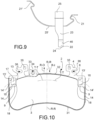
- a pad-and-spring assembly 1 or assembly 1 for a brake caliper 10 for disc brake is provided.
- Said assembly 1 comprises at least one brake pad 2 and at least one elastic device 5.
- an axial direction X-X is defined either coinciding with or parallel to the rotation axis of the disc (not shown) of said disc brake, a radial direction R-R orthogonal to the axial direction X-X, and a tangential direction T-T, orthogonal to both the axial direction X-X and to the radial direction R-R.
- the radial direction R-R is incident to the rotation axis of the brake disc.
- Said radial direction R-R defines a radially inward direction RI, directed towards the rotation axis of the brake disc, and a radially outward direction RO, opposite to the radially inward direction RI.
- the axial X-X, radial R-R and tangential T-T directions, as well as said radially inward direction RI and said radially outward direction RE, are also defined on a brake pad 2 when it is considered not associated with the brake caliper 10, and when said brake pad 2 is considered associated with at least one elastic device 5.
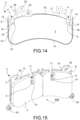
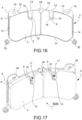
- Said at least one brake pad 2 comprises friction material 3, adapted to press against an exposed braking surface of the disc brake disc to apply the braking action, and a supporting plate 4 which supports said friction material 3.
- Said at least one elastic device 5 is adapted to apply an elastic biasing action directed in axial direction X-X to said brake pad 2 to move it away from the brake disc when the braking action ceases. In this manner, it is possible to minimize the occurrence of undesired residual braking torque.
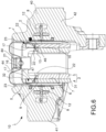
- Said supporting plate 4 comprises a surface facing the disc 6, intimately associated with said friction material 3, and a plate back 7, axially opposite to said surface facing the disc 6 and adapted to face, either directly or indirectly, thrust means 8 of the brake caliper 10 which can be associated with said assembly 1.
- said surface facing the disc 6 is partially covered with at least one layer of friction material 3.
- said thrust means 8 of the brake caliper 10 comprise at least one piston 8 of at least one cylinder-piston assembly.
- the at least one cylinder of said at least one cylinder-piston assembly associated with said piston 8 is formed entirely in the caliper body 40 of the brake caliper 10.
- Said at least one piston 8 may be actuated hydraulically and/or electromechanically.
- Said friction material 3 comprises a radially inner edge, adapted to face the rotation axis of the brake disc, and a radially outer edge 13, radially opposite to said radially inner edge.
- Said radially outer edge 13 of the friction material 3 defines the at least one outer radial dimension level of the friction material 3 with its tangential extension 13' on a plane which contains said surface facing the disc 6 of the supporting plate 4.
- said surface facing the disc 6 of the supporting plate 4 defines a lying plane which contains it, although said supporting plate 4 has discontinuities, such as through holes and/or through slots.
- the outer radial dimension level of the friction material 3 is meant defined on a plane coincident with and parallel to the surface facing the disc 6 of the plate, even though the surface facing the disc 6 has discontinuities, such as through openings 17.
- said outer radial dimension level of the friction material 3 is defined by drawing at least one tangential extension 13' parallel to the tangential direction T-T from the radially outer edge 13 of the friction material 3 evaluated in its length which is furthest from the rotation axis of the brake disc which can be associated with said assembly 1.
- the outer radial dimension level of the friction material is given by the radially outermost portion of friction material 3.
- said disc facing surface 6 of the supporting plate 4 comprises at least one free portion 9 or free surface 9, which is free from the contact with the friction material 3 and adapted to face a braking surface of the brake disc which can be associated with said assembly 1, said free portion 9 is located radially inside with respect to said at least one tangential extension 13' of the radially outer edge 13 of the friction material 3.
- said at least one free portion 9 of the surface facing the disc 6 of the supporting plate 4 of the brake pad 2 is delimited in the radially outward direction RO by said radially outer edge 13 and/or at least one of its tangential extensions 13', and preferably by the tangential extension 13' of said radially outer edge.
- said friction material 3 has at least one recess, so as to face said at least one free portion 9 of the disc facing surface 6 of the supporting plate 4, said friction material recess defining on said friction material 3 at least one recess edge surface 15 facing in radially outward direction RO and located at an innermost radial height than said tangential extension 13' of the radially outer edge of the friction material 3.
- said free surface 9 of the surface facing the disc 6 of the supporting plate 4 of brake pad 2 comprises at least one through opening edge 16 which at least partially delimits a through opening 17 in axial direction X-X through said supporting plate 4 of brake pad 2.
- said brake pad 2 comprises at least one through opening 17 which axially connects said plate back 7 with said free surface 9.
- said through opening 17 is through across said brake pad 2.
- said through opening 17 opens at said friction material recess 3.
- said free surface 9 of the supporting plate 4 comprises an opening margin surface, which at least partially surrounds said through opening edge 16, and preferably surrounds said through opening edge 16 in radially inner manner, i.e. in the radially inward direction RI. In this manner, the supporting portion 22 is prevented from interfering with the friction material 3 under operating conditions, e.g. during braking.
- said through hole 17 is a through hole surrounded by a closed periphery.
- said closed periphery of the through opening 17 is partially described on said free surface 9.
- the closed periphery of the through opening 17 crosses the tangential extension 13' of the radially outer edge 13 of the friction material 3.
- said through opening 17 is a through slot surrounded by an open periphery, and preferably said open periphery of the through opening 17 leads to a radially outward direction RO.
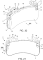
- said at least one elastic device 5 has a body comprising at least one connecting portion 21, 21', adapted to connect to the body of the brake caliper 10 which can be associated with said assembly 1, and at least one supporting portion 22, which rests against said opening edge 16 of the free surface 9 of the supporting plate 4 axially crossing said passing opening 17 of the supporting plate 4.
- said at least one supporting portion 22 extends at least in axial direction X-X, and preferably also in radial direction R-R, through said through opening 17 to abut against said through opening edge 16 described on the free portion 9 of the surface facing the disc 6 of the supporting plate 4 of the brake pad 2.
- said brake pad 2 is pushed by thrust means 8 to abut against an approachable braking surface of a brake disc, concurrently applying an axial thrust action against the support portion 22 of the elastic device 5, which deforms itself by charging elastically.
- the through opening edge 16 slides on said supporting portion 22 of the elastic device 5, thereby deforming it elastically in the radially outward direction RO while remaining in contact therewith.
- the spring supporting portion 22 applies said elastic biasing action to move the brake pad 2 away from the disc.
- said through opening edge 16 is facing in radially outward direction RO.
- said through opening edge 16 delimits said through opening 17 in radially inward direction RI.
- said at least one elastic device 5 has a body further comprising at least one arm 23 which extends, preferably in radial direction R-R, between said supporting portion 22 and said connecting portion 21, 21' of the body of the elastic device 5.
- said at least one arm 23 directly connects said supporting portion 22 to said connecting portion 21, 21', if it can do so, but still allows said elastic device 5 to apply a direct elastic biasing action at least in axial direction X-X between the body of the brake caliper 10 and the brake pad 2.
- said at least one arm 23 extends for at least one portion thereof either facing and/or in contact with said plate back 7 of the supporting plate 6 of the brake pad 2.
- said at least one arm 23 extends radially outwards with respect to said tangential extension 13' of the radially outer edge 13 of the friction material 3.
- the body of said elastic device 5 comprises at least one further connecting portion 25, 25', e.g. an arm, which connects said connecting portion 21, 21' to said at least one arm 23, thereby forming a preferably arch-shaped path, so as to take said connecting portion 21, 21' to an axial level comprised between the radial extensions of the braking surfaces of the brake disc associated with said assembly 1.
- said elastic device 5 comprises a cross-shaped body, and at least two axially opposite arms 23, each ending with at least one supporting portion 22, so as to bias two opposite brake pads 2 in the axial direction X-X away from the brake disc.
- said assembly 1 further comprises at least one further opposite brake pad 2 so as to comprise two opposite brake pads 2, adapted to press against opposite braking surfaces of a brake disc which can be associated with said assembly 1.
- said assembly 1 comprises a further separate elastic device 5, so as to comprise two elastic devices 5 arranged tangentially side-by-side both acting with their resting portions 22 on the same brake pad 2 and/or on the same pair of opposite brake pads 2.
- said at least one arm 23 extends in radially outward direction RO from said supporting portion 22 of the elastic device 5 between said plate back 7 and the body of the brake caliper 10 which can be associated with said assembly 1.
- said through opening edge 16 comprises an arch-shaped resting length 18, so as to allow the resting portion 22 of the elastic device 5 to rest in a minimum contact area, ideally coinciding with a single point of contact between elastic device 5 and through opening edge 16. In this manner, it is possible to apply a ready axial elastic bias on the brake pad.
- said through opening edge 16 is associated with a slide 11 which extends between said plate back 7 and said free surface 9 of the supporting plate 4.
- said slide 11 is inclined with respect to the axial direction X-X by a predefined inclination angle.
- said slide 11 is inclined towards the rotation axis of the brake disc which can be associated with said assembly 1.
- said slide 11 is inclined in the radially inward direction RI towards said opening edge 16, in other words, it is inclined in the radially inward direction RI moving along the axial direction X-X from said plate back 7 to said free surface 9 of the surface facing the disc 6 of the supporting plate 4.
- said predetermined inclination angle is substantially equal to said angle 20 formed between said supporting portion 22 and said arm 23 of the elastic device 5.
- said through opening 17 is surrounded by an eyelet 19 having a radially outward eyelet side 30.
- said eyelet 19 being axially offset with respect to the plate back 7 is preferably axially offset towards the brake disc which can be associated with said assembly 1, thus forming a resting portion seat 38 adapted to receive a portion of said support portion 22 of the elastic device 5.
- said supporting portion 22 comprises a radially inner surface 46 which goes into abutment onto said through opening edge 16, and an opposite radially outer surface 47.
- said radially outer surface 47 goes into abutment against said radially outer edge 30 of said eyelet 19.
- said at least one arm 23 of the elastic device 5 ends with a free end 24 defining said supporting portion 22.
- said free end 24 defining said supporting portion 22 at least axially protrudes from said arm 23. In this manner, it is possible for said supporting portion 22 to go into abutment against said through opening edge 16 placed radially internally with respect to said tangential extension 13' of the radially inner edge 13 of the friction material 3 without because of this interfering with the footprint of the pistons on the plate back 7 of the brake pad 2.
- footprint of the piston means one or more areas in which, during the braking action, the piston 8 acts, either directly or indirectly, on the plate back 7 of the supporting plate of brake pad 2.
- at least one footprint of piston 8 is defined axially at the area of brake pad 2 on which the thrust means 8 act during the braking action.
- a radial dimension piston band 27 defined by the radial dimension of the piston footprint is defined on said plate back 7 of the supporting plate 4 of the brake pad 2.
- said piston footprint defines an outer radial piston level 28 substantially coinciding with the extension parallel to the tangential direction T-T on the plate back 7 of the radial height of the piston footprint evaluated in the farthest point thereof from the rotation axis of the disc.
- said piston footprint defines an inner radial piston level 29 substantially coinciding with the extension parallel to the tangential direction T-T on the plate back 7 of the radial height of the piston footprint evaluated in the closest point thereof to the rotation axis of the disc.
- said radial dimension piston band 27 is delimited in radial direction R-R by said outer radial piston level 28 and said inner radial piston level 29.
- Said radial dimension piston band 27, said outer radial piston level 28 and said inner radial piston level 29 are also defined on said surface facing the disc 6 of the supporting plate 4, by means of their axial extension through the supporting plate 4.
- said through opening edge 16 of the free surface 9 of the supporting plate 4 of the brake pad 2 on which said supporting portion 22 of the elastic element 5 rests is radially inside said outer radial piston level 28, and preferably is comprised in said radial dimension piston band 27.
- said free end 24 protrudes in axial direction X-X from said arm 23, thus forming an angle 20 with said arm 23.
- said angle 20 is greater than 90°.
- said angle 20 is comprised between 120° and 180°, preferably said angle 20 is substantially equal to 135°.
- said at least one arm 23 of the elastic device 5 is made in the form of a leaf, preferably made of spring steel.
- said arm 23 and said supporting portion 22 are made in a single piece.
- said at least one connection portion 21, 21' of elastic device 5 is adapted to be coupled to a portion of the brake caliper body 2 which can be associated with said assembly 1, and preferably at least one brake caliper bridge of said brake caliper body 10.
- said supporting plate 4 of the brake pad 2 comprises a plate radially inner edge 31, adapted to face the rotation axis of an associated disc brake disc, and an opposite plate radially outer edge 32, opposite to said plate radially inner edge 31.
- said radially outer plate edge 32 which defines a radially outer plate edge portion 33 on said surface facing the disc 6 of the supporting plate 4, radially between the radially outer plate edge 13 of the friction material 3 and the radially outer plate edge 32.
- said plate radially outer edge 32 delimits at least one wear sensor seat 34 adapted to receive at least one portion of a friction material wear signaling device.
- said plate radially outer edge 33 delimits at least one damper seat 35, adapted to receive at least one portion of a device for adjusting the vibration frequency of the brake pad, such as for example, an additional mass.
- said portion of plate radially outer edge 33 delimits at least one pin seat 36 adapted to receive at least one sliding pin 37 of said brake caliper 10 adapted to guide the movement of brake pad 2 with respect to the brake caliper body 10 both during the braking action and when the braking action ceases.
- said at least one sliding pin 37 also acts as a radial constraint to a radial elastic biasing action applied by said elastic device 5.
- said supporting portion 22 of the elastic device applies on said through opening edge 16 also a direct biasing action in the radially inward direction RI.
- said direct biasing action in the radially inward direction RI is contrasted by virtue of the provision of said sliding pins 37 that cooperate with the walls of said pin seat 36.
- said friction material 3 further comprises at least one side edge 14 facing tangential direction T-T and adapted to face the brake caliper 10 associated with said assembly 1.
- said at least one side edge 14 defines the outer radial dimension level of the friction material 3 with its tangential extension 14' on said surface facing the disc 6 of the supporting plate 4.
- said extension 14' can also not be parallel to the radial direction R-R but parallel to a definable middle axis brake pad 2.
- said free surface 9 is delimited in radially outward direction RO by said outer radial dimension level and in tangential direction T-T by said outer tangential dimension of the friction material 3 and by said friction material 3.
- said free surface 9 is delimited in radially outward direction RO by said outer radial dimension level and tangentially T-T by said friction material 3.
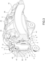
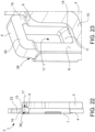
- a disc brake 10 comprising a caliper body 40, adapted to be arranged straddling a brake disc which can be associated with the brake caliper 10 and at least one pad-and-spring assembly 1, according to any one of the preceding embodiments.
- said brake caliper 10 further comprises thrust means 8 adapted to press at least one brake pad 2 against the facing braking surfaces of the brake disc which can be associated with said brake caliper 10.
- said thrust means comprise at least one piston 8, actuated hydraulically and/or electro-mechanically, said at least one piston 8 being associated with at least one retraction device 12, or roll-back device 12, adapted to retract by a predefined entity said piston 8 with respect to the caliper body 40 when the braking command ceases.
- said retraction device 12 also acts as a knock-back device to extract, if necessary, said piston 8 from the body of the caliper 40 by a predetermined entity.
- said thrust means 8 of the brake caliper 10 define said footprint of the piston and said radial dimension piston band 27.
- Said caliper body 40 comprises a pair of opposing elongated portions 41, 42, each adapted to face, either directly or indirectly by means of at least one brake pad 2, one of the opposite braking surfaces of a brake disc which can be associated with said brake caliper 10.
- Said caliper body 40 further comprises at least one caliper bridge 43, 44, which connects said elongated portions 41, 42 together being arranged straddling an associable disc brake.
- said at least one caliper bridge 43 or 44 are at least three caliper bridges, in which said at least three caliper bridges delimit caliper body radial openings 45 between them.
- said at least three caliper bridges comprise at least one central bridge 43 and at least one pair of side bridges 44, tangentially opposite to said central bridge 43.
- said at least one connecting portion 21, 21' of at least one elastic device 5 of the assembly 1 is coupled to at least two caliper bridges 43 and 44, and preferably a central bridge 43 and a side bridge 44, being arranged inside said at least one radial caliper opening 45.
- two separate elastic devices 5 are provided placed tangentially side by side, so as to couple both to the central bridge 43 and also to couple each to one of the end bridges 44.
- said caliper body 40 is a fixed-type caliper body having opposite thrust means 8 for brake pads housed in said opposite elongated portions 41, 42.
Claims (10)
- Belag-und-Feder-Anordnung (1) für einen Bremssattel (10) für eine Scheibenbremse, wobei eine axiale Richtung (X-X) entweder zusammenfallend mit oder parallel zu der Rotationsachse einer Bremsscheibe der Scheibenbremse, eine radiale Richtung (R-R) orthogonal zu der axialen Richtung (X-X), und eine tangentiale Richtung (T-T) orthogonal zu sowohl der axialen Richtung (X-X) als auch der radialen Richtung (R-R) definiert sind, wobei die radiale Richtung (R-R) eine radial nach innen weisende Richtung (RI), die in Richtung der Rotationsachse der Bremsscheibe gerichtet ist, und eine radial nach außen weisende Richtung (RO), die gegensätzlich zu der radial nach innen weisenden Richtung (RI) ist; definiert, wobei die Anordnung umfasst:- wenigstens einen Bremsbelag (2), der Friktionsmaterial (3) und eine Stützplatte (4) umfasst, die das Friktionsmaterial (3) stützt;- wenigstens eine elastische Vorrichtung (5), die dazu geeignet ist, eine in axiale Richtung (X-X) gerichtete elastische Vorspannungsaktion auf den Bremsbelag (2) auszuüben, um ihn von der Bremsscheibe wegzubewegen, wenn die Bremsaktion aufhört;wobei:- die Stützplatte (4) eine der Scheibe (6) zuweisenden Fläche, die aufs Engste dem Friktionsmaterial (3) zugeordnet ist, und eine Plattenrückseite (7) umfasst, die axial der der Scheibe zuweisenden Fläche (6) gegenüberliegend und dazu geeignet ist, zu Schubmittel (8) des Bremssattels (10) zu weisen, der der Anordnung zugeordnet sein kann;- das Friktionsmaterial (3) eine radial innere Kante, die dazu geeignet ist, zu der Rotationsachse der Bremsscheibe zu weisen, und eine radial äußere Kante (13) umfasst, die der radial inneren Kante radial gegenüberliegt;- die radial äußere Kante (13) des Friktionsmaterials (3) das äußere radiale Dimensionsniveau des Friktionsmaterials (3) mit seiner tangentialen Ausdehnung (13`) auf der zu der Scheibe (6) weisenden Fläche der Stützplatte (4) definiert;- die zu der Scheibe weisende Fläche (6) der Stützplatte (4) wenigstens eine freie Fläche (9) umfasst, die frei von dem Kontakt mit dem Friktionsmaterial (3) ist und dazu geeignet ist, zu einer Bremsfläche der Bremsscheibe zu weisen, die der Anordnung (1) zugeordnet sein kann, wobei der freie Abschnitt (9) radial innen angeordnet ist mit Bezug zu der wenigstens einen tangentialen Ausdehnung (13`) der radial äußeren Kante (13) des Friktionsmaterials (3);- die freie Fläche (9) der zu der Scheibe weisenden Fläche (6) der Stützplatte (4) des Bremsbelags (2) wenigstens eine Durchgangs-Öffnungs-Kante (16) umfasst, die wenigstens teilweise eine Durchgangsöffnung (17) in axiale Richtung (X-X) durch die Stützplatte (4) des Bremsbelags (2) begrenzt;und wobei die wenigstens eine elastische Vorrichtung (5) einen Körper aufweist, umfassend:- wenigstens einen Verbindungsabschnitt (21, 21'), der dazu geeignet ist, sich mit dem Körper des Bremssattels (10) zu verbinden, der der Anordnung (1) zugeordnet sein kann; dadurch gekennzeichnet, dass- wenigstens ein Stützabschnitt (22), der an der Durchgangs-Öffnungs-Kante (16) der freien Fläche (9) der Stützplatte (4) aufliegt, das Durchgangsloch (17) der Stützplatte (4) axial kreuzt, um eine elastische Vorspannaktion direkt in axiale Richtung (X-X) auf die Durchgangs-Öffnungs-Kante (16) von der Durchgangsöffnung (17) auszuüben.
- Anordnung (1) nach Anspruch 1, wobei die Durchgangs-Öffnungs-Kante (16) in radial nach außen weisende Richtung (RO) weist; und/oder wobei- die Durchgangs-Öffnungs-Kante (16) die Durchgangsöffnung (17) in radial nach innen weisende Richtung (RI) begrenzt.
- Anordnung (1) nach Anspruch 1 oder 2, wobei die Durchgangs-Öffnungs-Kante (16) eine bogenförmige Auflagelänge (18) umfasst, um dem Auflageabschnitt (22) der elastischen Vorrichtung (5) zu erlauben, in einem minimalen Kontaktbereich aufzuliegen, idealerweise zusammenfallend mit einem einzigen Kontaktpunkt zwischen elastischer Vorrichtung (5) und Durchgangs-Öffnungs-Kante (16); und/oder wobei- die Durchgangs-Öffnungs-Kante (16) einem Schieber zugeordnet ist, der sich zwischen der Plattenrückseite (7) und der freien Fläche (9) der Stützplatte (4) erstreckt, wobei der Schieber mit Bezug zu der axialen Richtung (X-X) durch einen vorbestimmten Neigungswinkel geneigt ist; und/oder wobei der vorbestimmte Neigungswinkel im Wesentlichen gleich dem zwischen dem Stützabschnitt (22) und dem Arm (23) der elastischen Vorrichtung (5) gebildete Winkel (20) ist; und/oder wobei- der Schieber (11) in Richtung der Rotationsachse der Bremsscheibe geneigt ist, die der Anordnung (1) zugeordnet sein kann; und/oder wobei- die Durchgangsöffnung (17) von einer Öse (19) umgeben ist, die eine radial äußere Ösenseite (30) aufweist; und/oder die Öse (19) mit Bezug zu der Plattenrückseite (7) axial versetzt ist und vorzugsweise in Richtung der Bremsscheibe, die der Anordnung (1) zugeordnet sein kann, axial versetzt ist, um somit einen Auflageabschnittsitz (38) zu bilden, der dazu geeignet ist, einen Abschnitt des Stützabschnitts (22) der elastischen Vorrichtung (5) zu empfangen.
- Anordnung (1) nach einem der vorangehenden Ansprüche, wobei das Friktionsmaterial (3) wenigstens eine Vertiefung aufweist, so dass es zu wenigstens einem freien Abschnitt (9) der zu der Scheibe weisenden Fläche (6) der Stützplatte (4) weist, wobei die Friktionsmaterialvertiefung auf dem Friktionsmaterial (3) wenigstens eine Vertiefungskantenfläche (15) definiert, die in radial nach außen weisender Richtung (RO) weist und an einer innersten radialen Höhe als die tangentiale Ausdehnung (13') der radial äußeren Kante (13) des Friktionsmaterials (3) angeordnet ist, und/oder wobei- die Durchgangs-Öffnung (17) die Friktionsmaterialvertiefung (3) öffnet; und/oder wobei- die freie Fläche (9) der Stützplatte (4) eine Öffnungs-Rand-Fläche umfasst, die wenigstens teilweise die Durchgangs-Öffnungs-Kante (16) umgibt, und vorzugsweise die Durchgangs-Öffnungs-Kante (16) in der radial nach innen weisenden Richtung (RI) umgibt.
- Anordnung (1) nach einem der vorangehenden Ansprüche, wobei wenigstens eine elastische Vorrichtung (5) einen Körper aufweist, der ferner wenigstens einen Arm (23) umfasst, der sich, vorzugsweise in radiale Richtung (R-R), zwischen dem Stützabschnitt (22) und dem Verbindungsabschnitt (21, 21') des Körpers der elastischen Vorrichtung (5) erstreckt; und/oder wobei- der wenigstens eine Arm (23) sich für wenigstens einem Abschnitt davon erstreckt, der entweder zu der Plattenrückseite (7) der Stützplatte (6) des Bremsbelags (2) weist und/oder mit ihr in Kontakt ist; und/oder wobei- der wenigstens eine Arm (23) der elastischen Vorrichtung (5) mit einem freien Ende (24) endet, das den Stützabschnitt (22) definiert; und/oder wobei- das freie Ende (24), das den Stützabschnitt (22) definiert, wenigstens axial von dem Arm (23) hervorsteht; und/oder wobei- das freie Ende (24) in axialer Richtung (X-X) von dem Arm (23) hervorsteht, um somit einen Winkel (20) mit dem Arm (23) zu bilden;- der Winkel (20) größer ist als 90°, wobei vorzugsweise der Winkel (20) zwischen 120° und 180° beträgt, wobei der Winkel (20) vorzugsweise im Wesentlichen gleich ist mit 135°.
- Anordnung (1) nach einem der vorangehenden Ansprüche, wobei die Durchgangsöffnung (17) ein Durchgangsloch ist, das von einem geschlossenen Umfang umgeben ist;
oder wobei
die Durchgangsöffnung (17) ein Durchgangsschlitz ist, der von einer offenen Umgebung umgeben ist, und vorzugsweise sich die offene Umgebung der Durchgangsöffnung (17) in radial nach außen weisender Richtung (RO) öffnet. - Anordnung (1) nach einem der vorangehenden Ansprüche, wobei ein Radial-Dimension-Kolben-Band (27), das durch die radiale Dimension der Kolbengrundfläche definiert ist, auf der Plattenrückseite (7) der Stützplatte (4) des Bremsbelags (2) definiert ist;- die Kolbengrundfläche ein äußeres radiales Kolbenniveau (28) definiert, das im Wesentlichen mit der Erstreckung parallel zu der tangentialen Richtung (T-T) auf der Plattenrückseite (7) der radialen Höhe der Kolbengrundfläche zusammenfällt, die in dem weitesten Punkt davon zu der Rotationsachse der Scheibe ausgewertet ist; und/oder wobei- die Kolbengrundfläche ein inneres radiales Kolbenniveau (29) definiert, das im Wesentlichen mit der Erstreckung parallel zu der tangentialen Richtung (T-T) auf der Plattenrückseite (7) der radialen Höhe der Kolbengrundfläche zusammenfällt, die in dem nächsten Punkt davon zu der Rotationsachse der Scheibe ausgewertet ist; und/oder wobei- das Radial-Dimension-Kolben-Band (27) in radialer Richtung (R-R) durch das äußere radiale Kolbenniveau (28) und das innere radiale Kolbenniveau (29) begrenzt ist; und/oder wobei die Durchgangs-Öffnungs-Kante (16) der freien Fläche (9) der Stützplatte (4) des Bremsbelags (2), an der der Stützabschnitt (22) des elastischen Elements (5) aufliegt, radial innerhalb des äußeren radialen Kolbenniveaus (28) ist, und vorzugsweise in dem Radial-Dimension-Kolben-Band (27) umfasst ist; und/oder wobeider Begriff "Kolbengrundfläche" einen oder mehrere Bereiche meint, in dem/denen während der Bremsaktion, der Kolben (8) agiert, entweder direkt oder indirekt, auf der Plattenrückseite (17) der Stützplatte (4) des Bremsbelags (2).
- Anordnung (1) nach einem der vorangehenden Ansprüche, wobei die elastische Vorrichtung (5) einen kreuzförmigen Körper, und wenigstens zwei axial gegenüberliegende Arme (23) umfasst, die jeweils mit wenigstens einem Stützabschnitt (22) enden, um wenigstens zwei gegenüberliegende Bremsbeläge (2) in der axialen Richtung (X-X) von der Bremsscheibe weg vorzuspannen; so dass die Anordnung (1) ferner wenigstens einen weiteren gegenüberliegenden Bremsbelag (2) umfasst, um ein Paar von gegenüberliegenden Bremsbelägen (2) zu umfassen, das dazu geeignet ist, gegen gegenüberliegende Bremsflächen der Scheibenbremse zu drücken, die der Anordnung (1) zugeordnet sein kann; und/oder wobei- die Anordnung (1) eine weitere getrennte elastische Vorrichtung (5) umfasst, um zwei elastische Vorrichtungen (5) zu umfassen, die tangential nebeneinander angeordnet sind, wobei beide mit ihren Auflageabschnitten (22) auf den gleichen Bremsbelag (2) und/oder auf das gleiche Paar gegenüberliegender Bremsbeläge (2) agieren.
- Bremssattel (10) für eine Scheibenbremse umfassend einen Sattelkörper (40), der dazu geeignet ist, eine Bremsscheibe überspannend angeordnet zu sein, die dem Bremssattel (10) und wenigstens einer Belag-und-Feder-Anordnung (1) nach einem der vorangehenden Ansprüche zugeordnet sein kann.
- Bremssattel (10) nach Anspruch 9, ferner umfassend Schubmittel (8), die dazu geeignet sind, wenigstens einen Bremsbelag (2) gegen die zuweisende Bremsfläche der Bremsscheibe zu drücken, die dem Bremssattel (10) zugeordnet sein kann; und/oder wobei der Sattelkörper (40) umfasst:- ein Paar gegenüberliegender länglicher Abschnitte (41, 42), die jeweils dazu geeignet sind, entweder direkt oder indirekt mittels wenigstens eines Bremsbelags (2), zu einer der gegenüberliegenden Bremsflächen der Bremsscheibe zu weisen, die dem Bremssattel (10) zugeordnet sein kann;- wenigstens eine Sattelbrücke (43, 44), die die länglichen Abschnitte (41, 42) verbindet, die zusammen dazu angeordnet sind, eine zuordenbare Scheibenbremse zu überspannen; und/oder wobei- wenigstens eine Sattelbrücke (43 oder 44) wenigstens drei Sattelbrücken sind, die wenigstens eine zentrale Brücke (43) und wenigstens ein Paar von Seitenbrücken (44) umfasst, die tangential der zentralen Brücke (43) gegenüberliegen, und wobei die wenigstens drei Sattelbrücken gegenseitig radiale Brücken-Körper-Öffnungen (45) begrenzen; und/oder wobei- der wenigstens eine Verbindungsabschnitt (21, 21') der wenigstens einen elastischen Vorrichtung (5) der Anordnung (1) mit wenigstens zwei Sattelbrücken (43 und 44) gekoppelt ist, und vorzugsweise mit einer zentralen Brücke (43) und einer Seitenbrücke (44), innerhalb der wenigstens einen radialen Sattelöffnung (45) angeordnet.
Applications Claiming Priority (2)
| Application Number | Priority Date | Filing Date | Title |
|---|---|---|---|
| IT102018000020572A IT201800020572A1 (it) | 2018-12-20 | 2018-12-20 | Assieme di pastiglia e molla per una pinza freno |
| PCT/IB2019/060550 WO2020128710A1 (en) | 2018-12-20 | 2019-12-09 | Pad-and-spring assembly for a brake caliper |
Publications (2)
| Publication Number | Publication Date |
|---|---|
| EP3899307A1 EP3899307A1 (de) | 2021-10-27 |
| EP3899307B1 true EP3899307B1 (de) | 2023-06-14 |
Family
ID=66286558
Family Applications (1)
| Application Number | Title | Priority Date | Filing Date |
|---|---|---|---|
| EP19821206.0A Active EP3899307B1 (de) | 2018-12-20 | 2019-12-09 | Belag- und federanordnung für bremssattel |
Country Status (6)
| Country | Link |
|---|---|
| US (1) | US20220065312A1 (de) |
| EP (1) | EP3899307B1 (de) |
| JP (1) | JP2022514620A (de) |
| CN (1) | CN113195923B (de) |
| IT (1) | IT201800020572A1 (de) |
| WO (1) | WO2020128710A1 (de) |
Families Citing this family (7)
| Publication number | Priority date | Publication date | Assignee | Title |
|---|---|---|---|---|
| IT201800006498A1 (it) * | 2018-06-20 | 2019-12-20 | Molla per pastiglie d'attrito in una pinza per freno a disco | |
| IT202100000749A1 (it) | 2021-01-18 | 2022-07-18 | Brembo Spa | Molla a nastro ed assieme di molla a nastro e pastiglia freno |
| IT202100000743A1 (it) | 2021-01-18 | 2022-07-18 | Brembo Spa | Molla a nastro ed assieme di molla a nastro e pastiglia freno |
| IT202100025361A1 (it) | 2021-10-04 | 2023-04-04 | Brembo Spa | Molla, assieme di molla e pastiglia freno, assieme di corpo pinza |
| CN217440641U (zh) * | 2022-04-29 | 2022-09-16 | 蔚来汽车科技(安徽)有限公司 | 制动钳组件、制动器及车辆 |
| CN116900740B (zh) * | 2023-09-07 | 2023-11-14 | 烟台环球机床装备股份有限公司 | 一种可倾回转工作台 |
| CN117329244B (zh) * | 2023-12-01 | 2024-02-02 | 山西强力矿用设备制造有限公司 | 液压湿式制动集成结构 |
Family Cites Families (15)
| Publication number | Priority date | Publication date | Assignee | Title |
|---|---|---|---|---|
| US3783980A (en) * | 1971-10-13 | 1974-01-08 | Itt | Brake lining holding arrangement for spot-type disc brakes |
| IN154071B (de) * | 1981-01-09 | 1984-09-15 | Lucas Industries Ltd | |
| DE4112947C2 (de) | 1991-04-20 | 1999-09-16 | Teves Gmbh Alfred | Bremsbacke mit Haltefeder |
| DE59409536D1 (de) | 1994-12-07 | 2000-10-26 | Continental Teves Ag & Co Ohg | Bremsbelagsatz für Schwimmsattel-Scheibenbremse |
| DE10136235A1 (de) | 2000-09-14 | 2002-07-11 | Continental Teves Ag & Co Ohg | Teilbelagsscheibenbremse sowie zugehöriger Bremsbelag mit einer Haltevorrichtung für den Bremsbelag |
| IT1395169B1 (it) * | 2009-08-13 | 2012-09-05 | Freni Brembo Spa | Molla per pinza freno di freno a disco e pinza freno dotata di tale molla |
| IT1401114B1 (it) | 2010-07-05 | 2013-07-12 | Freni Brembo Spa | Guaina di protezione di un gruppo pistone-cilindro di un freno a disco |
| JP2012189188A (ja) * | 2011-03-14 | 2012-10-04 | Akebono Brake Ind Co Ltd | ディスクブレーキ用パッドの戻し装置 |
| ITMI20111739A1 (it) | 2011-09-27 | 2013-03-28 | Freni Brembo Spa | Dispositivo di arretramento di un pistone |
| ITPD20120214A1 (it) | 2012-07-04 | 2014-01-05 | Freni Brembo Spa | Pinza di freno a disco |
| ITPD20120398A1 (it) * | 2012-12-20 | 2014-06-21 | Freni Brembo Spa | Pinza per freno a disco |
| US20140305753A1 (en) | 2013-04-12 | 2014-10-16 | Akebono Brake Corporation | Pad retraction clip |
| US10316912B2 (en) * | 2014-04-08 | 2019-06-11 | Freni Brembo S.P.A. | Disc brake pad, spring for disc brake caliper and disk brake caliper assembly |
| ITUB20155653A1 (it) * | 2015-11-17 | 2017-05-17 | Freni Brembo Spa | Pinza per freno a disco, metodo di fabbricazione di una pinza e molla per pinza |
| DE102017222639A1 (de) * | 2017-01-31 | 2018-08-02 | Continental Teves Ag & Co. Ohg | Festsattelkraftfahrzeugteilbelagscheibenbremse mit einer Stahlblechbügellüftspielfeder |
-
2018
- 2018-12-20 IT IT102018000020572A patent/IT201800020572A1/it unknown
-
2019
- 2019-12-09 JP JP2021535780A patent/JP2022514620A/ja active Pending
- 2019-12-09 EP EP19821206.0A patent/EP3899307B1/de active Active
- 2019-12-09 US US17/415,233 patent/US20220065312A1/en active Pending
- 2019-12-09 WO PCT/IB2019/060550 patent/WO2020128710A1/en unknown
- 2019-12-09 CN CN201980084781.8A patent/CN113195923B/zh active Active
Also Published As
| Publication number | Publication date |
|---|---|
| US20220065312A1 (en) | 2022-03-03 |
| JP2022514620A (ja) | 2022-02-14 |
| CN113195923B (zh) | 2023-09-08 |
| EP3899307A1 (de) | 2021-10-27 |
| IT201800020572A1 (it) | 2020-06-20 |
| WO2020128710A1 (en) | 2020-06-25 |
| CN113195923A (zh) | 2021-07-30 |
Similar Documents
| Publication | Publication Date | Title |
|---|---|---|
| EP3899307B1 (de) | Belag- und federanordnung für bremssattel | |
| US8567574B2 (en) | Brake caliper | |
| US5103939A (en) | Spot type disc brake | |
| EP1218645B1 (de) | Kolben für einen zylinder und kolbeneinheit für eine scheibenbremse | |
| US3708043A (en) | Disc brakes | |
| US4082167A (en) | Sliding caliper-type disc brake and support structure therefore | |
| US11773932B2 (en) | Pad return spring for a disc brake caliper body | |
| US4055238A (en) | Anti-squeal device in disc brake | |
| JPH026927B2 (de) | ||
| JP2017521616A (ja) | ブレーキ・ディスクから離れるようパッドを移動させるデバイスを備えたアッセンブリ | |
| KR100391471B1 (ko) | 자동 변속기 다판 클러치의 리턴 스프링 | |
| JPH0556411B2 (de) | ||
| US4261443A (en) | Disc brakes for vehicles | |
| US6955247B2 (en) | Disc brake, in particular for a motor vehicle, pad for such a brake and anti-noise shim for such a pad | |
| CN110892170B (zh) | 制动卡钳与至少一个衬垫的组件 | |
| JPS6222679Y2 (de) | ||
| US7216745B2 (en) | Mounting friction elements to disc brakes | |
| EP0027714A1 (de) | Bremsklötze für Fahrzeugscheibenbremsen und Fahrzeugscheibenbremsen | |
| CA2461986A1 (en) | Flexible brake shoe | |
| EP3717317B1 (de) | Bremssattelkolben, bremssattel, und -herstellungsverfahren | |
| USRE32470E (en) | Disc brakes for vehicles | |
| JPS63312526A (ja) | ディスクブレーキ用スプリング | |
| CN113272571B (zh) | 用于盘式制动器和制动器卡钳的衬垫-弹簧组件 | |
| US3240296A (en) | Automatic adjusting and kickback device | |
| CN217682944U (zh) | 一种具有新型活塞结构的摩托车、自行车制动卡钳 |
Legal Events
| Date | Code | Title | Description |
|---|---|---|---|
| STAA | Information on the status of an ep patent application or granted ep patent |
Free format text: STATUS: UNKNOWN |
|
| STAA | Information on the status of an ep patent application or granted ep patent |
Free format text: STATUS: THE INTERNATIONAL PUBLICATION HAS BEEN MADE |
|
| PUAI | Public reference made under article 153(3) epc to a published international application that has entered the european phase |
Free format text: ORIGINAL CODE: 0009012 |
|
| STAA | Information on the status of an ep patent application or granted ep patent |
Free format text: STATUS: REQUEST FOR EXAMINATION WAS MADE |
|
| 17P | Request for examination filed |
Effective date: 20210616 |
|
| AK | Designated contracting states |
Kind code of ref document: A1 Designated state(s): AL AT BE BG CH CY CZ DE DK EE ES FI FR GB GR HR HU IE IS IT LI LT LU LV MC MK MT NL NO PL PT RO RS SE SI SK SM TR |
|
| DAV | Request for validation of the european patent (deleted) | ||
| DAX | Request for extension of the european patent (deleted) | ||
| GRAP | Despatch of communication of intention to grant a patent |
Free format text: ORIGINAL CODE: EPIDOSNIGR1 |
|
| STAA | Information on the status of an ep patent application or granted ep patent |
Free format text: STATUS: GRANT OF PATENT IS INTENDED |
|
| INTG | Intention to grant announced |
Effective date: 20230104 |
|
| GRAS | Grant fee paid |
Free format text: ORIGINAL CODE: EPIDOSNIGR3 |
|
| GRAA | (expected) grant |
Free format text: ORIGINAL CODE: 0009210 |
|
| STAA | Information on the status of an ep patent application or granted ep patent |
Free format text: STATUS: THE PATENT HAS BEEN GRANTED |
|
| AK | Designated contracting states |
Kind code of ref document: B1 Designated state(s): AL AT BE BG CH CY CZ DE DK EE ES FI FR GB GR HR HU IE IS IT LI LT LU LV MC MK MT NL NO PL PT RO RS SE SI SK SM TR |
|
| REG | Reference to a national code |
Ref country code: CH Ref legal event code: EP |
|
| REG | Reference to a national code |
Ref country code: DE Ref legal event code: R096 Ref document number: 602019031145 Country of ref document: DE |
|
| P01 | Opt-out of the competence of the unified patent court (upc) registered |
Effective date: 20230526 |
|
| REG | Reference to a national code |
Ref country code: AT Ref legal event code: REF Ref document number: 1579434 Country of ref document: AT Kind code of ref document: T Effective date: 20230715 |
|
| REG | Reference to a national code |
Ref country code: LT Ref legal event code: MG9D |
|
| REG | Reference to a national code |
Ref country code: NL Ref legal event code: MP Effective date: 20230614 |
|
| PG25 | Lapsed in a contracting state [announced via postgrant information from national office to epo] |
Ref country code: SE Free format text: LAPSE BECAUSE OF FAILURE TO SUBMIT A TRANSLATION OF THE DESCRIPTION OR TO PAY THE FEE WITHIN THE PRESCRIBED TIME-LIMIT Effective date: 20230614 Ref country code: NO Free format text: LAPSE BECAUSE OF FAILURE TO SUBMIT A TRANSLATION OF THE DESCRIPTION OR TO PAY THE FEE WITHIN THE PRESCRIBED TIME-LIMIT Effective date: 20230914 Ref country code: ES Free format text: LAPSE BECAUSE OF FAILURE TO SUBMIT A TRANSLATION OF THE DESCRIPTION OR TO PAY THE FEE WITHIN THE PRESCRIBED TIME-LIMIT Effective date: 20230614 |
|
| REG | Reference to a national code |
Ref country code: AT Ref legal event code: MK05 Ref document number: 1579434 Country of ref document: AT Kind code of ref document: T Effective date: 20230614 |
|
| PG25 | Lapsed in a contracting state [announced via postgrant information from national office to epo] |
Ref country code: RS Free format text: LAPSE BECAUSE OF FAILURE TO SUBMIT A TRANSLATION OF THE DESCRIPTION OR TO PAY THE FEE WITHIN THE PRESCRIBED TIME-LIMIT Effective date: 20230614 Ref country code: NL Free format text: LAPSE BECAUSE OF FAILURE TO SUBMIT A TRANSLATION OF THE DESCRIPTION OR TO PAY THE FEE WITHIN THE PRESCRIBED TIME-LIMIT Effective date: 20230614 Ref country code: LV Free format text: LAPSE BECAUSE OF FAILURE TO SUBMIT A TRANSLATION OF THE DESCRIPTION OR TO PAY THE FEE WITHIN THE PRESCRIBED TIME-LIMIT Effective date: 20230614 Ref country code: LT Free format text: LAPSE BECAUSE OF FAILURE TO SUBMIT A TRANSLATION OF THE DESCRIPTION OR TO PAY THE FEE WITHIN THE PRESCRIBED TIME-LIMIT Effective date: 20230614 Ref country code: HR Free format text: LAPSE BECAUSE OF FAILURE TO SUBMIT A TRANSLATION OF THE DESCRIPTION OR TO PAY THE FEE WITHIN THE PRESCRIBED TIME-LIMIT Effective date: 20230614 Ref country code: GR Free format text: LAPSE BECAUSE OF FAILURE TO SUBMIT A TRANSLATION OF THE DESCRIPTION OR TO PAY THE FEE WITHIN THE PRESCRIBED TIME-LIMIT Effective date: 20230915 |
|
| PG25 | Lapsed in a contracting state [announced via postgrant information from national office to epo] |
Ref country code: FI Free format text: LAPSE BECAUSE OF FAILURE TO SUBMIT A TRANSLATION OF THE DESCRIPTION OR TO PAY THE FEE WITHIN THE PRESCRIBED TIME-LIMIT Effective date: 20230614 |
|
| PG25 | Lapsed in a contracting state [announced via postgrant information from national office to epo] |
Ref country code: SK Free format text: LAPSE BECAUSE OF FAILURE TO SUBMIT A TRANSLATION OF THE DESCRIPTION OR TO PAY THE FEE WITHIN THE PRESCRIBED TIME-LIMIT Effective date: 20230614 |
|
| PGFP | Annual fee paid to national office [announced via postgrant information from national office to epo] |
Ref country code: GB Payment date: 20231220 Year of fee payment: 5 |
|
| PG25 | Lapsed in a contracting state [announced via postgrant information from national office to epo] |
Ref country code: IS Free format text: LAPSE BECAUSE OF FAILURE TO SUBMIT A TRANSLATION OF THE DESCRIPTION OR TO PAY THE FEE WITHIN THE PRESCRIBED TIME-LIMIT Effective date: 20231014 |
|
| PG25 | Lapsed in a contracting state [announced via postgrant information from national office to epo] |
Ref country code: SM Free format text: LAPSE BECAUSE OF FAILURE TO SUBMIT A TRANSLATION OF THE DESCRIPTION OR TO PAY THE FEE WITHIN THE PRESCRIBED TIME-LIMIT Effective date: 20230614 Ref country code: SK Free format text: LAPSE BECAUSE OF FAILURE TO SUBMIT A TRANSLATION OF THE DESCRIPTION OR TO PAY THE FEE WITHIN THE PRESCRIBED TIME-LIMIT Effective date: 20230614 Ref country code: RO Free format text: LAPSE BECAUSE OF FAILURE TO SUBMIT A TRANSLATION OF THE DESCRIPTION OR TO PAY THE FEE WITHIN THE PRESCRIBED TIME-LIMIT Effective date: 20230614 Ref country code: PT Free format text: LAPSE BECAUSE OF FAILURE TO SUBMIT A TRANSLATION OF THE DESCRIPTION OR TO PAY THE FEE WITHIN THE PRESCRIBED TIME-LIMIT Effective date: 20231016 Ref country code: IS Free format text: LAPSE BECAUSE OF FAILURE TO SUBMIT A TRANSLATION OF THE DESCRIPTION OR TO PAY THE FEE WITHIN THE PRESCRIBED TIME-LIMIT Effective date: 20231014 Ref country code: EE Free format text: LAPSE BECAUSE OF FAILURE TO SUBMIT A TRANSLATION OF THE DESCRIPTION OR TO PAY THE FEE WITHIN THE PRESCRIBED TIME-LIMIT Effective date: 20230614 Ref country code: CZ Free format text: LAPSE BECAUSE OF FAILURE TO SUBMIT A TRANSLATION OF THE DESCRIPTION OR TO PAY THE FEE WITHIN THE PRESCRIBED TIME-LIMIT Effective date: 20230614 Ref country code: AT Free format text: LAPSE BECAUSE OF FAILURE TO SUBMIT A TRANSLATION OF THE DESCRIPTION OR TO PAY THE FEE WITHIN THE PRESCRIBED TIME-LIMIT Effective date: 20230614 |
|
| PGFP | Annual fee paid to national office [announced via postgrant information from national office to epo] |
Ref country code: DE Payment date: 20231214 Year of fee payment: 5 |
|
| PG25 | Lapsed in a contracting state [announced via postgrant information from national office to epo] |
Ref country code: PL Free format text: LAPSE BECAUSE OF FAILURE TO SUBMIT A TRANSLATION OF THE DESCRIPTION OR TO PAY THE FEE WITHIN THE PRESCRIBED TIME-LIMIT Effective date: 20230614 |
|
| REG | Reference to a national code |
Ref country code: DE Ref legal event code: R026 Ref document number: 602019031145 Country of ref document: DE |
|
| PLBI | Opposition filed |
Free format text: ORIGINAL CODE: 0009260 |
|
| PLAX | Notice of opposition and request to file observation + time limit sent |
Free format text: ORIGINAL CODE: EPIDOSNOBS2 |
|
| 26 | Opposition filed |
Opponent name: VRI-PATENT MONITORING ASSOCIATION Effective date: 20240314 |
|
| PG25 | Lapsed in a contracting state [announced via postgrant information from national office to epo] |
Ref country code: DK Free format text: LAPSE BECAUSE OF FAILURE TO SUBMIT A TRANSLATION OF THE DESCRIPTION OR TO PAY THE FEE WITHIN THE PRESCRIBED TIME-LIMIT Effective date: 20230614 |
|
| REG | Reference to a national code |
Ref country code: CH Ref legal event code: PK Free format text: DIE PUBLIKATION VOM 27.03.2024 WURDE AM 24.04.2024 IRRTUEMLICHERWEISE ERNEUT PUBLIZIERT. LA PUBLICATION DU 27.03.2024 A ETE REPUBLIEE PAR ERREUR LE 24.04.2024. LA PUBBLICAZIONE DEL 27.03.2024 E STATA ERRONEAMENTE RIPUBBLICATA IL 24.04.2024. |
|
| PG25 | Lapsed in a contracting state [announced via postgrant information from national office to epo] |
Ref country code: SI Free format text: LAPSE BECAUSE OF FAILURE TO SUBMIT A TRANSLATION OF THE DESCRIPTION OR TO PAY THE FEE WITHIN THE PRESCRIBED TIME-LIMIT Effective date: 20230614 |