EP0716246B1 - Set of brake pads for floating caliper disc brake - Google Patents
Set of brake pads for floating caliper disc brake Download PDFInfo
- Publication number
- EP0716246B1 EP0716246B1 EP19940119288 EP94119288A EP0716246B1 EP 0716246 B1 EP0716246 B1 EP 0716246B1 EP 19940119288 EP19940119288 EP 19940119288 EP 94119288 A EP94119288 A EP 94119288A EP 0716246 B1 EP0716246 B1 EP 0716246B1
- Authority
- EP
- European Patent Office
- Prior art keywords
- brake
- pad
- rivet heads
- carrier plate
- brake pad
- Prior art date
- Legal status (The legal status is an assumption and is not a legal conclusion. Google has not performed a legal analysis and makes no representation as to the accuracy of the status listed.)
- Expired - Lifetime
Links
- 238000013016 damping Methods 0.000 claims description 53
- 238000000034 method Methods 0.000 claims 1
- 238000000465 moulding Methods 0.000 claims 1
- 238000004519 manufacturing process Methods 0.000 description 11
- 230000002093 peripheral effect Effects 0.000 description 3
- 238000003860 storage Methods 0.000 description 2
- 238000005266 casting Methods 0.000 description 1
- 238000006073 displacement reaction Methods 0.000 description 1
- 238000009434 installation Methods 0.000 description 1
- 239000000463 material Substances 0.000 description 1
- 239000002184 metal Substances 0.000 description 1
- 238000004080 punching Methods 0.000 description 1
Images


Classifications
-
- F—MECHANICAL ENGINEERING; LIGHTING; HEATING; WEAPONS; BLASTING
- F16—ENGINEERING ELEMENTS AND UNITS; GENERAL MEASURES FOR PRODUCING AND MAINTAINING EFFECTIVE FUNCTIONING OF MACHINES OR INSTALLATIONS; THERMAL INSULATION IN GENERAL
- F16D—COUPLINGS FOR TRANSMITTING ROTATION; CLUTCHES; BRAKES
- F16D65/00—Parts or details
- F16D65/0006—Noise or vibration control
-
- F—MECHANICAL ENGINEERING; LIGHTING; HEATING; WEAPONS; BLASTING
- F16—ENGINEERING ELEMENTS AND UNITS; GENERAL MEASURES FOR PRODUCING AND MAINTAINING EFFECTIVE FUNCTIONING OF MACHINES OR INSTALLATIONS; THERMAL INSULATION IN GENERAL
- F16D—COUPLINGS FOR TRANSMITTING ROTATION; CLUTCHES; BRAKES
- F16D55/00—Brakes with substantially-radial braking surfaces pressed together in axial direction, e.g. disc brakes
- F16D55/02—Brakes with substantially-radial braking surfaces pressed together in axial direction, e.g. disc brakes with axially-movable discs or pads pressed against axially-located rotating members
- F16D55/22—Brakes with substantially-radial braking surfaces pressed together in axial direction, e.g. disc brakes with axially-movable discs or pads pressed against axially-located rotating members by clamping an axially-located rotating disc between movable braking members, e.g. movable brake discs or brake pads
- F16D55/224—Brakes with substantially-radial braking surfaces pressed together in axial direction, e.g. disc brakes with axially-movable discs or pads pressed against axially-located rotating members by clamping an axially-located rotating disc between movable braking members, e.g. movable brake discs or brake pads with a common actuating member for the braking members
-
- F—MECHANICAL ENGINEERING; LIGHTING; HEATING; WEAPONS; BLASTING
- F16—ENGINEERING ELEMENTS AND UNITS; GENERAL MEASURES FOR PRODUCING AND MAINTAINING EFFECTIVE FUNCTIONING OF MACHINES OR INSTALLATIONS; THERMAL INSULATION IN GENERAL
- F16D—COUPLINGS FOR TRANSMITTING ROTATION; CLUTCHES; BRAKES
- F16D65/00—Parts or details
- F16D65/02—Braking members; Mounting thereof
- F16D65/04—Bands, shoes or pads; Pivots or supporting members therefor
- F16D65/092—Bands, shoes or pads; Pivots or supporting members therefor for axially-engaging brakes, e.g. disc brakes
Definitions
- the invention relates to a brake pad set for floating caliper disc brakes according to the preamble of the claim 1.
- a generic brake pad set is from DE 41 20 631 A1 known.
- the known brake pad set consists of two brake pads, which each have a back plate on the A friction lining on the front and a damping plate on the back is attached. The one to rest on the brake piston and Certain use on the inner axial side of the disc brake
- the brake pad has three projections on its back plate for fastening the damping plate and a retaining spring. The three protrusions are approximately in line in the circumferential direction arranged.
- the damping plate has as many holes for Passage of the projections on which it is riveted.
- the Brake pad intended for use on the outer axial side has two projections on its back plate, which, however, in radial direction are arranged one above the other.
- the corresponding Damping plate also has holes arranged for passage the ledges on.
- the object of the invention is to provide an improved brake pad set to specify, the lowest possible manufacturing costs for its manufacture attack.
- the solution is to create a uniform damping plate that Can be used for both the inner and outer brake pads is. This is a damping sheet metal tool and thus associated costs saved. There are also savings due to reduced interim storage.
- an inner brake pad Embodiment in that the damping plate in the Center of the brake pad anyway from the adjacent brake piston is pressed. Therefore, it is sufficient for complete attachment two rivet heads laterally spaced apart in the circumferential direction.
- the outer brake pad is in the usual designs of Floating caliper disc brakes by contacting two circumferentially spaced fingers of the floating caliper on the brake disc pressed.
- the two fingers are on the in Circumferential direction outer edge areas of the brake pad and press the damping plate onto the back plate here.
- two Rivet heads provided that are spaced apart in the radial direction are arranged in the middle of the lining carrier plate.
- one of the radially spaced, central Rivet heads when using the same facing carrier plate for the inner and outer brake pads for fastening at the same time serve the retaining spring.
- three can Rivet heads can be provided in the middle of the lining carrier plate, which are spaced in a line.
- All three exemplary embodiments described below the invention each relate to a brake pad set for Floating caliper disc brakes, each consisting of two brake pads consists.
- An inner brake pad 1 is on the system a brake piston of the floating caliper and an outer brake pad 2 for contact with an outer housing leg of the Floating saddle determined.
- Each brake pad 1, 2 has one Base plate, on the front (in the drawings not shown) a friction lining and on the back a damping plate attached to embossed rivet heads is.
- a first embodiment of the invention is in the figures 1 to 7 shown.
- One for the inner brake pad 1 certain pad carrier plate 3 is with two in the circumferential direction laterally arranged rivet heads 4, 5 and one in the middle between the two rivet heads 4, 5 arranged Provided rivet head 6.
- the rivet heads 4, 5, 6 are made of the material the base plate 3 formed by stamp and stand some from the plane of the plate in the axial direction Millimeters.
- One intended for the outer brake pad 2 Pad carrier plate 7 is with two rivet heads 8, 9 provided along a center line of the lining carrier plate 7 are arranged spaced apart in the radial direction.
- On Damping plate 10 is both for attachment to the back the inner lining carrier plate 3 and the outer Pad carrier plate 7 is provided.
- the damping plate 10 has three holes 11, 12, 13 for the passage of the rivet heads 4, 5, 6 the inner lining carrier plate 3 and two further holes 14, 15 for the passage of the rivet heads 8, 9 of the outer lining carrier plate 7 on. For the completion of the outer brake pad 2, the damping plate 10 on the pad carrier plate 7 and the two rivet heads 8, 9 by swapping riveted.
- the finished outer brake pad 2 is shown in Figure 6, the contours of the outer housing leg by the dashed lines 16 of the floating saddle are indicated. Man recognizes the two fingers of the outer housing leg, the on the outer peripheral regions of the damping plate in the circumferential direction 10 and apply this to the base plate Press 7. In the recessed area between the two The two rivet heads 8, 9 ensure good fingers Contact of the damping plate 10 on the lining carrier plate 7. Holes 11, 12, 13 of the damping plate remain in use free on the outer brake pad 2.
- the finished inner brake pad 1 is shown in FIG. After placing the damping plate 10 on the inner lining carrier plate 3 is still a retaining spring 17 on the middle rivet head 6 attached.
- the retaining spring 17 is made made of spring plate and has three spring arms 18 which in the Inside of a hollow brake piston engage the inside Attach brake pad 1 to the brake piston.
- To the passage the middle rivet head 6 has a retaining spring 17 opening not shown. This opening points just like that Rivet head 6 has a D-shaped cross section. This will the retaining spring 17 against rotation about the axis of the rivet head 6 secured.
- the inner brake pad 1 is completed.
- Figure 7 are the contours of the hollow brake piston indicated by the double dash 19.
- the Brake piston presses in the annular area between the Circles of the dash 19 the damping plate 10 against the Base plate 3.
- the outer peripheral areas in the circumferential direction of the damping plate 10 are by the rivet heads 4, 5 pressed.
- the holes 14, 15 of the damping plate 10 remain free with the inner brake pad 1.
- a second embodiment of the invention is in the Figures 8 to 10 shown.
- a topping plate 20 is both for the inner brake pad 1 and for the outer Brake pad 2 suitable.
- the topping plate 20 has therefore five rivet heads 4, 5, 6, 8, 9, which are basically the same are arranged as in the other lining carrier plates 3, 7.
- the pad carrier plate 20 can with the damping plate 10 both to an inner brake pad 1 and to one outer brake pad 2 can be combined.
- Riveted heads 8, 9 riveted are only for the inner brake pad 1 the rivet heads 4, 5 and after placing the retaining spring 17th the rivet head 6 and for the inner brake pad 2 only that Riveted heads 8, 9 riveted.
- the invention also includes embodiments in which for example, all five rivet heads 4, 5, 6, 8, 9 are riveted.
- the inner one is different Brake pad 1 from the outer brake pad 2 only by the retaining spring 17.
- a third preferred embodiment of the invention is in 11 to 14 shown.
- a modified damping plate 21 is provided with a central hole 22 which has a circular cross section. On the central axis of the damping plate 21 is at a radial distance from the hole 22 another hole 23 is arranged with an oval cross section. In the peripheral edge areas of the lateral Damping plate, two further holes 24, 25 are arranged, which also have an oval cross section and essentially are in line with the central hole 22. The longer axes of the holes 23, 24, 25 are each open the middle hole 22 aligned.
- a modified base plate 26 has a central rivet head 27 with D-shaped cross section leading to passage through hole 22 of the damping plate 21 is determined. Three more rivet heads 28, 29, 30 each have a circular cross section and are intended for passage through holes 23, 24, 25 and arranged accordingly.
- the inner brake pad 1 is created by placing the damping plate 21 on the pad carrier plate 26, by plugging the holding spring 17 and by staggering the middle Rivet head 27 and the side rivet heads 29, 30 is a tolerance compensation through the oval cross section of the holes 24, 25 between the damping plate 21 and the lining carrier plate 26 manufactured.
- the one protruding through hole 23 Rivet head 28 remains untangled.
- the outer brake pad 2 is also created by laying on of the damping plate 21 on the lining carrier plate 26, wherein then only rivets the rivet heads 27 and 28 become. The lateral ones protruding through the holes 24, 25 Rivet heads 29, 30 remain untangled.
- brake linings are also part of the invention 1, 2 in which all four rivet heads 27, 28, 29, 30 are messed up.
- a brake pad set according to the invention can also consist of two identical brake pads 1, 2, either both designed with or both without retaining spring 17 are.
- outer brake pads 2 When using outer brake pads 2 with a universal backing plate 20 or 26 (see Figure 9 or Figure 14) must take care that the side rivet heads 4, 5 or 29, 30, the axially over the plate level of the lining carrier plate 20 or 26 protrude, a flat contact of the base plate 20 or 26 on the outer housing leg of the Ensure floating saddles.
- suitable floating saddle must be in a special way for this Be designed for use.
- One measure according to the invention consists in the exterior Legs of the floating saddle at the location of the rivet heads 4, Provide 5 or 29, 30 recesses into which the rivet heads 4, 5 or 29, 30 can protrude axially.
- the recesses In a first Embodiment, which is shown in FIG. 9 by the broken line 31 is indicated, the recesses have a circular Cross section on.
- the dash 32 In a second embodiment, which in Figure 9 is indicated by the dash 32, are Recesses in the form of a groove, which extends from Place the rivet heads 4, 5 and 29, 30 to the end of the outer Extend the housing leg in the radial direction.
Description
Die Erfindung betrifft einen Bremsbelagsatz für Schwimmsattel-Scheibenbremsen
gemäß dem Oberbegriff des Patentanspruchs
1.The invention relates to a brake pad set for floating caliper disc brakes
according to the preamble of the
Ein gattungsgemäßer Bremsbelagsatz ist aus der DE 41 20 631 A1 bekannt. Der bekannte Bremsbelagsatz besteht aus zwei Bremsbelägen, die jeweils eine Rückenplatte aufweisen, auf deren Vorderseite ein Reibbelag und auf deren Rückseite ein Dämpfungsblech befestigt ist. Der zur Anlage am Bremskolben und zur Verwendung auf der inneren Axialseite der Scheibenbremse bestimmte Bremsbelag besitzt drei Vorsprünge seiner Rückenplatte zur Befestigung des Dämpfungsblech und einer Haltefeder. Die drei Vorsprünge sind in Umfangsrichtung ungefähr in einer Linie angeordnet. Das Dämpfungsblech weist ebensoviele Löcher zum Durchgang der Vorsprünge auf, an denen es vernietet ist. Der zur Verwendung auf der äußeren Axialseite bestimmte Bremsbelag weist zwei Vorsprünge seiner Rückenplatte auf, die jedoch in radialer Richtung übereinander angeordnet sind. Das dazugehörige Dämpfungsblech weist ebenso angeordnete Löcher zum Durchgang der Vorsprünge auf. Zur Fertigung eines aus innerem und äußerem Bremsbelag bestehenden Bremsbelagsatzes sind zwei verschiedene Rückenplatten und zwei verschiedene Dämpfungsbleche erforderlich. Man benötigt jeweils zwei Fertigungswerkzeuge zum Stanzen der vier Bauteile und eine umfangreiche Zwischenlagerhaltung. Dies wirkt sich auf die Fertigungskosten aus. A generic brake pad set is from DE 41 20 631 A1 known. The known brake pad set consists of two brake pads, which each have a back plate on the A friction lining on the front and a damping plate on the back is attached. The one to rest on the brake piston and Certain use on the inner axial side of the disc brake The brake pad has three projections on its back plate for fastening the damping plate and a retaining spring. The three protrusions are approximately in line in the circumferential direction arranged. The damping plate has as many holes for Passage of the projections on which it is riveted. The Brake pad intended for use on the outer axial side has two projections on its back plate, which, however, in radial direction are arranged one above the other. The corresponding Damping plate also has holes arranged for passage the ledges on. To manufacture one from inside and outside Brake pad existing brake pad set are two different Back plates and two different damping plates required. Two manufacturing tools are required for punching of the four components and extensive interim storage. This affects manufacturing costs.
Ferner ist es aus der DE 43 18 744 C1 bekannt für eine Sschwimmsattel-Scheibenbremse einen Bremsbelagsatz mit gleichen Bremsbelägen sowie gleichen Dämpfungsblechen für die axiale Innen- und Außenseite zu verwenden. Dabei sind die Dämpfungsbleche jeweils an einem Vorsprung der Belagträgerplatte auf der dem Reibbelag abgewandten Seite mit der Belagträgerplatte vernietet. Die Befestigung der Dämpfungsbleche mit nur einer Nietung erweist sich hier als unzureichend, da das Dämpfungsblech nicht notwendigerweise flächig an der Belagträgerplatte anliegt und sich zumindeset partiell von der Belagträgerplatte lösen kann.Furthermore, it is known from DE 43 18 744 C1 for a Float caliper disc brake with a brake pad set with the same Brake pads and the same damping plates for the axial Use inside and outside. Here are the damping plates each on a projection of the pad carrier plate on the riveted side facing away from the friction lining with the lining carrier plate. The fastening of the damping plates with only one rivet proves to be inadequate here, since the damping plate does not necessarily lie flat against the lining carrier plate and at least partially detach from the base plate can.
Aufgabe der Erfindung ist es, einen verbesserten Bremsbelagsatz anzugeben, zu dessen Herstellung möglichst geringe Fertigungskosten anfallen.The object of the invention is to provide an improved brake pad set to specify, the lowest possible manufacturing costs for its manufacture attack.
Die Lösung der Aufgabe ergibt sich aus dem kennzeichnenden Teil
des Patentanspruchs 1. Im Prinzip besteht die erfindungsgemäße
Lösung darin, ein einheitliches Dämpfungsblech zu schaffen, das
sowohl für den inneren als auch für den äußeren Bremsbelag verwendbar
ist. Dabei wird ein Dämpfungsblechwerkzeug und die damit
verbundenen Kosten eingespart. Außerdem ergeben sich Einsparungen
durch eine verringerte Zwischenlagerhaltung. Im einzelnen
ergibt sich für einen inneren Bremsbelag eine vorteilhafte
Ausgestaltungsform dadurch, daß das Dämpfungsblech in der
Mitte des Bremsbelags ohnehin von dem anliegenden Bremskolben
angedrückt wird. Daher genügen zur vollständigen Befestigung
zwei in Umfangsrichtung seitlich beabstandet angeordnete Nietköpfe.
Der äußere Bremsbelag wird bei üblichen Bauformen von
Schwimmsattel-Scheibenbremsen durch Anlage an zwei in Umfangsrichtung
beabstandeten Fingern des Schwimmsattels an die Bremsscheibe
angedrückt. Die beiden Finger liegen an den in
Umfangsrichtung äußeren Randbereichen des Bremsbelags an und
drücken hier das Dämpfungsblech an die Rückenplatte an. Zur
vollständigen Befestigung des Dämpfungsblechs sind daher zwei
Nietköpfe vorgesehen, die in radialer Richtung im Abstand zueinander
in der Mitte der Belagträgerplatte angeordnet sind.The solution to the problem arises from the characterizing part
of
Falls der äußere Bremsbelag zusätzlich mit einer Haltefeder zur
Befestigung im hohlen Bremskolben versehen werden soll, empfiehlt
sich eine Ausführungsform gemäß Anspruch 2, nach der ein
zentraler Nietkopf für die Haltefeder in der Mitte der Belagträgerplatte
angeordnet ist. Eine weitere vorteilhafte Maßnahme
gemäß Anspruch 3 dient zur verdrehsicheren Befestigung der
Haltefeder, ohne daß dazu ein weiterer Nietkopf erforderlich
wäre.If the outer brake pad additionally with a retaining spring
Attachment in the hollow brake piston is recommended
an embodiment according to
Gemäß einer vorteilhaften Ausführungsform nach Anspruch 4 kann für den inneren Bremsbelag einer der radial beabstandeten, mittigen Nietköpfe bei Verwendung derselben Belagträgerplatte für den inneren und den äußeren Bremsbelag gleichzeitig zur Befestigung der Haltefeder dienen. Andererseits können auch drei Nietköpfe in der Mitte der Belagträgerplatte vorgesehen sein, die in einer Linie im Abstand zueinander angeordnet sind.According to an advantageous embodiment according to claim 4 for the inner brake pad one of the radially spaced, central Rivet heads when using the same facing carrier plate for the inner and outer brake pads for fastening at the same time serve the retaining spring. On the other hand, three can Rivet heads can be provided in the middle of the lining carrier plate, which are spaced in a line.
In einer Weiterbildung der Erfindung gemäß Anspruch 5 sind neben den Dämpfungsblechen auch die Belagträgerplatten der beiden Bremsbeläge gleich ausgestaltet, so daß sich die oben genannten Vorteile bezüglich der Fertigungskosten verdoppeln. Bei Verwendung der Belagträgerplatte für den äußeren Bremsbelag werden die beiden in den Randbereichen der Belagträgerplatte befindlichen Nietköpfe zur Befestigung des Dämpfungsblechs vernietet, bei Verwendung der Belagträgerplatte für den inneren Bremsbelag wird am mittleren Nietkopf die Blattfeder befestigt. Wenn nun eine universal verwendbare Belagträgerplatte mit vier oder fünf Nietköpfen beispielsweise zum Einsatz kommt, empfiehlt sich der Einfachheit halber eine Maßnahme, nach der beim inneren Bremsbelag nur die seitlichen und ggf. der zentrale Nietkopf und beim äußeren Bremsbelag nur die mittigen Nietköpfe vernietet werden. Dabei werden wiederum Fertigungskosten eingespart.In a further development of the invention, in addition to the damping plates also the brake pads of the two Brake pads designed the same, so that the above Double benefits in manufacturing costs. Using the pad carrier plate for the outer brake pad the two located in the edge areas of the lining carrier plate Riveted heads for attaching the damping plate, when using the pad carrier plate for the inner brake pad the leaf spring is attached to the middle rivet head. If so a universal base plate with four or five Rivet heads, for example, is recommended For the sake of simplicity, a measure according to the inner brake pad only the side and if necessary the central rivet head and only the central rivet heads are riveted to the outer brake pad become. In turn, manufacturing costs are saved.
Um die bei der Fertigung der Dämpfungsbleche und der Belagträgerplatten auftretenden Fertigungstoleranzen ausgleichen zu können, empfiehlt sich eine Merkmalskombination gemäß Anspruch 6, nach der im Dämpfungsblech ovale Locher zum Durchgang der Nietköpfe vorgesehen sind. Ohne diesen Toleranzausgleich bestünde die Gefahr, daß die Dämpfungsbleche auch nach dem Vernieten der Nietköpfe nicht eben an den Belagträgerplatten anliegen.In order to manufacture the damping plates and the backing plates compensate for any manufacturing tolerances a combination of features according to claim is recommended 6, after the holes in the damping plate oval for the passage of the Rivet heads are provided. Without this tolerance compensation the risk that the damping plates even after riveting the rivet heads do not lie flat against the lining carrier plates.
Eine weitere vorteilhafte Maßnahme, die die Verwendung einer
universellen Belagträgerplatte sowohl für den inneren als insbesondere
auch für den äußeren Bremsbelag ermöglicht, ergibt
sich aus der Merkmalskombination des Anspruchs 7. Um eine ebene
Anlage der oben genannten Finger des Schwimmsattels an der
Rückseite des äußeren Bremsbelags zu gewährleisten muß der äußere
Gehäuseschenkel an seiner Innenfläche zwei Ausnehmungen
aufweisen, in die die seitlichen Nietköpfe des äußeren Bremsbelags
in axialer Richtung hineinragen können. Diese Ausnehmungen
können beispielsweise einen runden Querschnitt haben, und
dienen dann gleichzeitig als Sicherung für den äußeren Bremsbelag
gegen radiales Herausfallen. Zum radialen Entfernen des
äußeren Bremsbelags müßte dieser dann zuerst einige Millimeter
in axialer Richtung bewegt werden, bis die Nietköpfe nicht mehr
in die Ausnehmungen hineinragen. Wenn andererseits wegen des
geringen axialen Einbauraums eine axiale Verschiebung des äußeren
Bremsbelags bei der Montage nicht erwünscht ist, empfiehlt
sich eine Ausführungsform gemäß Anspruch 8, nach der die Ausnehmungen
des äußeren Gehäuseschenkels jeweils in Form einer
Rinne ausgestaltet sind, die in radialer Richtung bis zum Ende
der Finger des Gehäuseschenkels reicht. Die Ausnehmungen nach
Anspruch 7 oder 8 werden zur Vermeidung weiterer Fertigungskosten
am besten gemäß Anspruch 9 beim Gießen des
Schwimmsattelgehäuses gleich mit eingeformt.Another advantageous measure that involves the use of a
universal base plate for both the inner and in particular
also allows for the outer brake pad results
itself from the combination of features of
Ausführungsbeispiele der Erfindung werden nachfolgend anhand der Zeichnungen näher erläutert.Exemplary embodiments of the invention are described below the drawings explained in more detail.
Es zeigen:
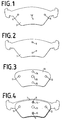
Figur 1- eine Belagrückenplatte für einen inneren Bremsbelag;
Figur 2- eine Belagrückenplatte für einen äußeren Bremsbelag;
Figur 3- ein erfindungsgemäßes Dämpfungsblech;
- Figur 4
- die Belagträgerplatte von
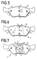
Figur 2 mit aufgelegtem Dämpfungsblech vonFigur 3; Figur 5- die Belagträgerplatte von
Figur 1 mit aufgelegtem Dämpfungsblech vonFigur 3; - Figur 6
- der aus der Anordnung von Figur 4 durch Vernieten entstandene fertige äußere Bremsbelag;
Figur 7- der aus der Anordnung von
Figur 5 nach Hinzufügen einer Blattfeder und durch Vernieten entstandene innere Bremsbelag; Figur 8- eine universell verwendbare Belagträgerplatte für eine zweite Ausführungsform der Erfindung;
Figur 9- ein äußerer Bremsbelag, der aus der Belagträgerplatte
von
Figur 8 und dem Dämpfungsblech vonFigur 3 besteht; Figur 10- ein innerer Bremsbelag, der ebenfalls aus der Belagträgerplatte
von
Figur 8 und dem Dämpfungsblech vonFigur 3 unter Hinzufügung einer Blattfeder besteht; Figur 11- ein weiteres Dämpfungsblech für eine dritte Ausführungsform der Erfindung;
Figur 12- eine weitere Belagträgerplatte für die dritte Ausführungsform der Erfindung;
Figur 13- ein aus dem
Dämpfungsblech von Figur 11 und derBelagträgerplatte von Figur 12 unter Hinzufügung einer Haltefeder zusammengesetzter innerer Bremsbelag; Figur 14- ein aus dem
Dämpfungsblech von Figur 11 und derBelagträgerplatte von Figur 12 zusammengesetzter äußerer Bremsbelag.
- Figure 1
- a pad backing plate for an inner brake pad;
- Figure 2
- a pad backing plate for an outer brake pad;
- Figure 3
- a damping plate according to the invention;
- Figure 4
- the pad carrier plate of Figure 2 with the damping plate of Figure 3;
- Figure 5
- the pad carrier plate of Figure 1 with the damping plate of Figure 3;
- Figure 6
- the finished outer brake lining resulting from the arrangement of FIG. 4 by riveting;
- Figure 7
- the inner brake lining resulting from the arrangement of FIG. 5 after adding a leaf spring and by riveting;
- Figure 8
- a universally usable base plate for a second embodiment of the invention;
- Figure 9
- an outer brake pad consisting of the pad carrier plate of Figure 8 and the damping plate of Figure 3;
- Figure 10
- an inner brake pad, which also consists of the pad carrier plate of Figure 8 and the damping plate of Figure 3 with the addition of a leaf spring;
- Figure 11
- another damping plate for a third embodiment of the invention;
- Figure 12
- another pad carrier plate for the third embodiment of the invention;
- Figure 13
- an inner brake pad composed of the damping plate from FIG. 11 and the pad carrier plate from FIG. 12 with the addition of a retaining spring;
- Figure 14
- an outer brake pad composed of the damping plate from FIG. 11 and the pad carrier plate from FIG.
Alle drei im folgenden beschriebenen Ausführungsbeispiele
der Erfindung betreffen jeweils einen Bremsbelagsatz für
Schwimmsattel-Scheibenbremsen, der jeweils aus zwei Bremsbelägen
besteht. Ein innerer Bremsbelag 1 ist zur Anlage an
einem Bremskolben des Schwimmsattels und ein äußerer Bremsbelag
2 zur Anlage an einem äußeren Gehäuseschenkel des
Schwimmsattels bestimmt. Jeder Bremsbelag 1, 2 besitzt eine
Belagträgerplatte, auf deren Vorderseite (in den Zeichnungen
nicht dargestellt) ein Reibbelag und auf deren Rückseite
ein Dämpfungsblech an durchgeprägten Nietköpfen befestigt
ist.All three exemplary embodiments described below
the invention each relate to a brake pad set for
Floating caliper disc brakes, each consisting of two brake pads
consists. An
Ein erstes Ausführungsbeispiel der Erfindung ist in den Figuren
1 bis 7 dargestellt. Eine für den inneren Bremsbelag
1 bestimmte Belagträgerplatte 3 ist mit zwei in Umfangsrichtung
seitlich angeordneten Nietköpfen 4, 5 und einem in
der Mitte zwischen den beiden Nietköpfen 4, 5 angeordnetem
Nietkopf 6 versehen. Die Nietköpfe 4, 5, 6 sind aus dem Material
der Belagträgerplatte 3 durch Stempel herausgeformt
und stehen aus der Plattenebene in axialer Richtung einige
Millimeter hervor. Eine für den äußeren Bremsbelag 2 bestimmte
Belagträgerplatte 7 ist mit zwei Nietköpfen 8, 9
versehen, die längs einer Mittellinie der Belagträgerplatte
7 in radialer Richtung beabstandet angeordnet sind. Ein
Dämpfungsblech 10 ist zur Befestigung auf der Rückseite sowohl
der inneren Belagträgerplatte 3 als auch der äußeren
Belagträgerplatte 7 vorgesehen. Das Dämfpungsblech 10 weist
drei Löcher 11, 12, 13 zum Durchgang der Nietköpfe 4, 5, 6
der inneren Belagträgerplatte 3 und zwei weitere Löcher 14,
15 zum Durchgang der Nietköpfe 8, 9 der äußeren Belagträgerplatte
7 auf. Für die Fertigstellung des äußeren Bremsbelags
2 wird das Dämpfungsblech 10 auf die Belagträgerplatte
7 aufgelegt und die beiden Nietköpfe 8, 9 durch Vertaumelung
vernietet.A first embodiment of the invention is in the figures
1 to 7 shown. One for the
Der fertige äußere Bremsbelag 2 ist in Figur 6 dargestellt,
wobei durch die Strichelung 16 die Konturen des äußeren Gehäuseschenkels
des Schwimmsattels mit angedeutet sind. Man
erkennt die beiden Finger des äußeren Gehäuseschenkels, die
an den in Umfangsrichtung äußeren Randbereichen des Dämpfungsblechs
10 anliegen und dieses an die Belagträgerplatte
7 andrücken. In dem ausgesparten Bereich zwischen den beiden
Fingern sorgen die zwei Nietköpfe 8, 9 für eine gute
Anlage des Dämpfungsblechs 10 an der Belagträgerplatte 7.
Die Löcher 11, 12, 13 des Dämpfungsblechs bleiben bei Verwendung
am äußeren Bremsbelag 2 frei.The finished
In Figur 7 ist der fertige innere Bremsbelag 1 dargestellt.
Nach dem Auflegen des Dämpfungsblechs 10 auf die innere Belagträgerplatte
3 wird noch eine Haltefeder 17 auf den
mittleren Nietkopf 6 aufgesteckt. Die Haltefeder 17 besteht
aus Federblech und besitzt drei Federarme 18, die in das
Innere eines hohlen Bremskolbens eingreifen, um den inneren
Bremsbelag 1 am Bremskolben zu befestigen. Zum Durchgang
des mittleren Nietkopfes 6 besitzt die Haltefeder 17 eine
nicht gezeigte Öffnung. Diese Öffnung weist genauso wie der
Nietkopf 6 einen D-förmigen Querschnitt auf. Dadurch wird
die Haltefeder 17 gegen Verdrehen um die Achse des Nietkopfs
6 gesichert. Nach dem Vernieten des Nietkopfs 6 und
der Nietköpfe 4, 5 ist der innere Bremsbelag 1 fertiggestellt.
In der Figur 7 sind die Konturen des hohlen Bremskolbens
durch die doppelte Strichelung 19 angedeutet. Der
Bremskolben drückt in dem ringförmigen Bereich zwischen den
Kreisen der Strichelung 19 das Dämpfungsblech 10 gegen die
Belagträgerplatte 3. Die in Umfangsrichtung äußeren Randbereiche
des Dämpfungsblechs 10 werden durch die Nietköpfe 4,
5 angedrückt. Die Löcher 14, 15 des Dämpfungsblechs 10
bleiben beim inneren Bremsbelag 1 frei.The finished
Ein zweites Ausführungsbeispiel der Erfindung ist in den
Figuren 8 bis 10 dargestellt. Eine Belagträgerplatte 20 ist
sowohl für den inneren Bremsbelag 1 als auch für den äußeren
Bremsbelag 2 geeignet. Die Belagträgerplatte 20 besitzt
daher fünf Nietköpfe 4, 5, 6, 8, 9, die im Prinzip genauso
angeordnet sind wie bei den anderen Belagträgerplatten 3,
7. Die Belagträgerplatte 20 kann mit dem Dämpfungsblech 10
sowohl zu einem inneren Bremsbelag 1 als auch zu einem
äußeren Bremsbelag 2 kombiniert werden. Zur Einsparung von
Fertigungskosten werden für den inneren Bremsbelag 1 nur
die Nietköpfe 4, 5 und nach dem Auflegen der Haltefeder 17
der Nietkopf 6 und für den inneren Bremsbelag 2 nur die
Nietköpfe 8, 9 vernietet. Infolgedessen bleiben beim inneren
Bremsbelag 1 die durch die Löcher 14, 15 des Dämpfungsblechs
10 ragenden Nietköpfe 8, 9 und beim äußeren Bremsbelag
die durch die Löcher 11, 12, 13 ragenden Nietköpfe 4,
5, 6 unvernietet.A second embodiment of the invention is in the
Figures 8 to 10 shown. A topping
Zur Erfindung gehören aber auch Ausführungsformen, bei denen
beispielsweise stets alle fünf Nietköpfe 4, 5, 6, 8, 9
vernietet sind. In diesem Fall unterscheidet sich der innere
Bremsbelag 1 vom äußeren Bremsbelag 2 nur durch die Haltefeder
17. Aber auch Ausführungsformen bei denen beide
Bremsbeläge 1, 2 eine Halterfeder 17 oder beide Bremsbeläge
1, 2 keine Haltefeder 17 und gegebenenfalls keinen Nietkopf
6 aufweisen, gehören zur Erfindung.However, the invention also includes embodiments in which
for example, all five
Eine dritte bevorzugte Ausführungsform der Erfindung ist in
den Figuren 11 bis 14 dargestellt. Ein modifiziertes Dämpfungsblech
21 ist mit einem mittleren Loch 22 versehen, das
einen kreisrunden Querschnitt aufweist. Auf der Mittelachse
des Dämpfungsblechs 21 ist im radialen Abstand zum Loch 22
ein weiteres Loch 23 mit einem ovalen Querschnitt angeordnet.
In den in Umfangsrichtung seitlichen Randbereichen des
Dämpfungsblechs sind zwei weitere Löcher 24, 25 angeordnet,
die ebenfalls einen ovalen Querschnitt aufweisen und im wesentlichen
in einer Linie mit dem mittleren Loch 22 liegen.
Die längeren Achsen der Löcher 23, 24, 25 sind jeweils auf
das mittlere Loch 22 ausgerichtet. Eine modifizierte Belagträgerplatte
26 besitzt einen mittleren Nietkopf 27 mit
D-förmigem Querschnitt, der zum Durchgang durch das Loch 22
des Dämpfungsblechs 21 bestimmt ist. Drei weitere Nietköpfe
28, 29, 30 besitzen jeweils kreisrunden Querschnitt und
sind zum Durchgang durch die Löcher 23, 24, 25 bestimmt und
entsprechend angeordnet.A third preferred embodiment of the invention is in
11 to 14 shown. A modified damping
Der innere Bremsbelag 1 entsteht durch Auflegen des Dämpfungsblechs
21 auf die Belagträgerplatte 26, durch Aufstecken
der Haltefeder 17 und durch Vertaumeln des mittleren
Nietkopfs 27 und der seitlichen Nietköpfe 29, 30. Dabei
wird durch den ovalen Querschnitt der Löcher 24, 25 ein Toleranzausgleich
zwischen dem Dämpfungsblech 21 und der Belagträgerplatte
26 hergestellt. Der durch das Loch 23 ragende
Nietkopf 28 bleibt unvertaumelt.The
Der äußere Bremsbelag 2 entsteht ebenfalls durch Auflegen
des Dämpfungsblechs 21 auf die Belagträgerplatte 26, wobei
anschließend lediglich die Nietköpfe 27 und 28 vertaumelt
werden. Die durch die Löcher 24, 25 ragenden seitlichen
Nietköpfe 29, 30 bleiben unvertaumelt.The
Selbstverständlich gehören zur Erfindung auch Bremsbeläge
1, 2 bei denen jeweils alle vier Nietköpfe 27, 28, 29, 30
vertaumelt sind. Ein erfindungsgemäßer Bremsbelagsatz kann
auch aus zwei gleichen Bremsbelägen 1, 2 bestehen, die entweder
beide mit oder beide ohne Haltefeder 17 ausgestaltet
sind.Of course, brake linings are also part of the
Bei der Verwendung von äußeren Bremsbelägen 2, die mit einer
universell verwendbaren Belagträgerplatte 20 oder 26
(siehe Figur 9 oder Figur 14) versehen sind, muß dafür Sorge
getragen werden, daß die seitlichen Nietköpfe 4, 5 bzw.
29, 30, die axial über die Plattenebene der Belagträgerplatte
20 bzw. 26 herausragen, eine ebene Anlage der Belagträgerplatte
20 bzw. 26 am äußeren Gehäuseschenkel des
Schwimmsattels gewährleisten. Ein zur Verwendung mit dem
genannten erfindungsgemäß ausgestalteten äußeren Bremsbelag
2 geeigneter Schwimmsattel muß in besonderer Weise für diese
Verwendung ausgestaltet sein.When using
Eine erfindungsgemäße Maßnahme besteht darin, im äußeren
Schenkel des Schwimmsattels an der Stelle der Nietköpfe 4,
5 bzw. 29, 30 Ausnehmungen vorzusehen, in die die Nietköpfe
4, 5 bzw. 29, 30 axial hineinragen können. In einer ersten
Ausführungsform, die in Figur 9 durch die Strichelung 31
angedeutet ist, weisen die Ausnehmungen einen kreisförmigen
Querschnitt auf. In einer zweiten Ausführungsform, die in
Figur 9 durch die Strichelung 32 angedeutet ist, sind die
Ausnehmungen in Form einer Rinne ausgebildet, die sich vom
Ort der Nietköpfe 4, 5 bzw. 29, 30 bis zum Ende des äußeren
Gehäuseschenkels in radialer Richtung erstrecken.One measure according to the invention consists in the exterior
Legs of the floating saddle at the location of the rivet heads 4,
Provide 5 or 29, 30 recesses into which the rivet heads
4, 5 or 29, 30 can protrude axially. In a first
Embodiment, which is shown in FIG. 9 by the
Claims (9)
- Set of brake pads for floating-caliper disc brakes which includes at least one brake pad (1) that is intended for the inner axial side of a floating caliper for abutment on a brake piston and at least one brake pad (2) for the external axial side, with each brake pad (1, 2) including a pad carrier plate (3, 7, 20, 26) provided with a friction lining and having on its back side embossed rivet heads (4, 5, 6, 8, 9, 27, 28, 29, 30) to which a damping sheet (10, 21) is attached, with both brake pads (1, 2) having equal damping sheets (10, 21),
characterized in that the damping sheets have at least holes (11, 12, 13 or 22, 24, 25) for the passage of the rivet heads (4, 5, 6 or 27, 29, 30) of the inner pad carrier plate (3) and holes (14, 15 or 22, 23) for the passage of the rivet heads (8, 9 or 27, 28) of the outer pad carrier plate (7), wherein the axially inner pad carrier plate (3) includes lateral rivet heads (4, 5, 29, 30) which are spaced in a circumferential direction and arranged in lateral fringe areas of the pad carrier plate (3), and the axially outer pad carrier plate (7) includes two centric rivet heads (8, 9) which are arranged generally along a line of symmetry of the pad carrier plate (7) spaced from each other in a radial direction. - Set of brake pads as claimed in claim 1,
characterized in that a central rivet head (6, 7) is arranged generally on the connecting line of the two lateral rivet heads (4, 5 or 29, 30) in the middle of at least the inner pad carrier plate (3, 20, 26). - Set of brake pads as claimed in claim 2,
characterized in that the central rivet head (6, 27) which is provided for attaching a retaining spring (17) on the inboard brake pad (1) close to the piston has a D-shaped cross-section as a rotation-preventing mechanism. - Set of brake pads as claimed in claim 2 or 3,
characterized in that the central rivet head (6, 27) forms one of the two centric rivet heads (8, 9 or 27, 28). - Set of brake pads as claimed in any one of the preceding claims,
characterized in that the inboard brake pad (1) and the outboard brake pad (2) are composed of equal pad carrier plates (20, 26) with rivet heads (4, 5, 6 or 27, 29, 30) and equal damping sheets (10, 21) with holes (11, 12, 13 or 22, 24, 25) for the passage of the corresponding rivet heads (4, 5, 6 or 27, 29, 30), wherein the outer and inner pad carrier plates (20, 26) especially have the same number of rivet heads (4, 5, 6, 8, 9 or 27, 28, 29, 30) in the same arrangement, and in that in the inboard brake pad (1) only the lateral rivet heads (4, 5 or 29, 30) and, optionally, the central rivet head (6 or 27) and in the outboard brake pad (2) only the centric rivet heads (8, 9 or 27, 28) are riveted, preferably by wobble-riveting. - Set of brake pads as claimed in any one of the preceding claims,
characterized in that the centric rivet heads (8, 9 or 28) and the lateral rivet heads (4, 5 or 29, 30) have a circular cross-section and the associated holes (23, 24, 25) of the damping sheet (21) have an oval or elongated cross-section for tolerance compensation, with the longer axes of the holes (23, 24, 25) being aligned towards a central hole (22) respectively towards the middle of the damping sheet (21). - Floating-caliper disc brake with a set of brake pads as claimed in any one of claims 5 to 6,
characterized in that an axially external housing leg which is arranged on the side of the floating caliper remote from the brake piston includes two recesses on the circumferentially outer fringe areas of its inner surface that abuts on the brake pad (2), with the lateral rivet heads (4, 5, 29, 30) of the outboard brake pad (2) projecting into the said recesses. - Floating-caliper disc brake as claimed in claim 7,
characterized in that the recesses extend in the shape of a groove until the radially inner end of the axially external housing leg. - Floating-caliper disc brake as claimed in claim 7 or 8, characterized in that the recesses are shaped during the molding process of the floating caliper.
Priority Applications (3)
| Application Number | Priority Date | Filing Date | Title |
|---|---|---|---|
| EP19940119288 EP0716246B1 (en) | 1994-12-07 | 1994-12-07 | Set of brake pads for floating caliper disc brake |
| DE59409536T DE59409536D1 (en) | 1994-12-07 | 1994-12-07 | Brake pad set for floating caliper disc brake |
| ES94119288T ES2149836T3 (en) | 1994-12-07 | 1994-12-07 | BRAKE LINING SET FOR A FLOATING CALIPER DISC BRAKE. |
Applications Claiming Priority (1)
| Application Number | Priority Date | Filing Date | Title |
|---|---|---|---|
| EP19940119288 EP0716246B1 (en) | 1994-12-07 | 1994-12-07 | Set of brake pads for floating caliper disc brake |
Publications (2)
| Publication Number | Publication Date |
|---|---|
| EP0716246A1 EP0716246A1 (en) | 1996-06-12 |
| EP0716246B1 true EP0716246B1 (en) | 2000-09-20 |
Family
ID=8216512
Family Applications (1)
| Application Number | Title | Priority Date | Filing Date |
|---|---|---|---|
| EP19940119288 Expired - Lifetime EP0716246B1 (en) | 1994-12-07 | 1994-12-07 | Set of brake pads for floating caliper disc brake |
Country Status (3)
| Country | Link |
|---|---|
| EP (1) | EP0716246B1 (en) |
| DE (1) | DE59409536D1 (en) |
| ES (1) | ES2149836T3 (en) |
Families Citing this family (5)
| Publication number | Priority date | Publication date | Assignee | Title |
|---|---|---|---|---|
| WO2001006374A2 (en) | 1999-07-16 | 2001-01-25 | Intertrust Technologies Corp. | System and method for securing an untrusted storage |
| DE102017220789B4 (en) | 2017-07-28 | 2023-08-10 | Continental Automotive Technologies GmbH | Friction pad retaining spring for improved brake piston fixation |
| CN108626285A (en) * | 2018-07-01 | 2018-10-09 | 德清县海昌汽车零配件有限公司 | A kind of more contact point brake facings being conducive to heat dissipation |
| IT201800020572A1 (en) | 2018-12-20 | 2020-06-20 | Freni Brembo Spa | ASSEMBLY OF PAD AND SPRING FOR A BRAKE CALIPER |
| IT201800020581A1 (en) | 2018-12-20 | 2020-06-20 | Freni Brembo Spa | Pad and spring assembly for disc brake and brake caliper |
Family Cites Families (7)
| Publication number | Priority date | Publication date | Assignee | Title |
|---|---|---|---|---|
| FR2347572A2 (en) * | 1976-04-08 | 1977-11-04 | Ferodo Sa | IMPROVEMENTS TO BRAKE COMPONENTS |
| JPS58207535A (en) * | 1982-05-25 | 1983-12-03 | Nissan Motor Co Ltd | Disc brake |
| JPS58211032A (en) * | 1982-05-31 | 1983-12-08 | Nissan Motor Co Ltd | Disc brake |
| US4603760A (en) * | 1985-09-03 | 1986-08-05 | General Motors Corporation | Slotted insulator and disc brake assembly using same |
| DE4101599A1 (en) * | 1991-01-21 | 1992-07-23 | Teves Gmbh Alfred | Brake block for disc brakes - has relative play between damping plate and fixing projections to compensate for high temperatures |
| DE4120631A1 (en) * | 1991-01-21 | 1992-12-24 | Teves Gmbh Alfred | BRAKE PAD FOR DISC BRAKES |
| DE4318744C1 (en) * | 1993-06-05 | 1994-09-01 | Teves Gmbh Alfred | Floating calliper disc brake for motor vehicles |
-
1994
- 1994-12-07 EP EP19940119288 patent/EP0716246B1/en not_active Expired - Lifetime
- 1994-12-07 ES ES94119288T patent/ES2149836T3/en not_active Expired - Lifetime
- 1994-12-07 DE DE59409536T patent/DE59409536D1/en not_active Expired - Lifetime
Also Published As
| Publication number | Publication date |
|---|---|
| EP0716246A1 (en) | 1996-06-12 |
| ES2149836T3 (en) | 2000-11-16 |
| DE59409536D1 (en) | 2000-10-26 |
Similar Documents
| Publication | Publication Date | Title |
|---|---|---|
| EP1506352B1 (en) | Brake lining for the disk brake of a vehicle | |
| DE4120631A1 (en) | BRAKE PAD FOR DISC BRAKES | |
| EP1898115B1 (en) | Vehicle disc brake | |
| EP0023881B1 (en) | Commercial-vehicle wheel for single or dual assembly | |
| DE1993752U (en) | DISC BRAKE. | |
| DE2800502A1 (en) | ANTI-RATE SPRING FOR A VEHICLE DISC BRAKE | |
| DE3939120C2 (en) | Brake disc, especially for a motor vehicle clutch | |
| DE3230700A1 (en) | BEARINGS | |
| DE3419235A1 (en) | CLUTCH MECHANISM | |
| DE19956968A1 (en) | Brake block bar for disc brakes has U-sections set between side edges of friction brake block and anchorage support section to prevent rattling | |
| DE3910154C2 (en) | Leaf spring arrangement for holding down the brake pad carrier in a disc brake | |
| DE202013101402U1 (en) | Brake lining for disc brake disc brakes, especially for rail vehicles | |
| EP0731288A1 (en) | Method for producing a brake pad and backing plate therefor | |
| DE2602552C2 (en) | Intermediate disk for vehicle brakes | |
| EP0716246B1 (en) | Set of brake pads for floating caliper disc brake | |
| DE4110869C2 (en) | Fixed caliper partial brake disc brake | |
| DE102018001999A1 (en) | brake lining | |
| DE102015122563A1 (en) | Brake lining for a disc brake, disc brake, downholder for brake pads of a disc brake | |
| DE102015102865A1 (en) | Sheet metal element with hole, sheet metal part and assembly part as well as production process | |
| DE102016103396B4 (en) | Disc brake pad and brake pad set | |
| AT391171B (en) | FRICTION CLUTCH | |
| DE102015122569A1 (en) | Disc brake, brake pad for a disc brake, hold-down for attaching brake pads | |
| DE4126197A1 (en) | FLOATING FRAME DISC BRAKE WITH COMFORTABLE BRAKE SHOE ARRANGEMENT | |
| DE4340451A1 (en) | Set of brake linings for floating caliper disc brakes | |
| DE102015122558A1 (en) | Disc brake and hold-down for attaching brake pads in a disc brake |
Legal Events
| Date | Code | Title | Description |
|---|---|---|---|
| PUAI | Public reference made under article 153(3) epc to a published international application that has entered the european phase |
Free format text: ORIGINAL CODE: 0009012 |
|
| 17P | Request for examination filed |
Effective date: 19941207 |
|
| AK | Designated contracting states |
Kind code of ref document: A1 Designated state(s): DE ES FR GB IT |
|
| 17Q | First examination report despatched |
Effective date: 19981201 |
|
| RAP1 | Party data changed (applicant data changed or rights of an application transferred) |
Owner name: CONTINENTAL TEVES AG & CO. OHG |
|
| GRAG | Despatch of communication of intention to grant |
Free format text: ORIGINAL CODE: EPIDOS AGRA |
|
| GRAG | Despatch of communication of intention to grant |
Free format text: ORIGINAL CODE: EPIDOS AGRA |
|
| GRAH | Despatch of communication of intention to grant a patent |
Free format text: ORIGINAL CODE: EPIDOS IGRA |
|
| GRAH | Despatch of communication of intention to grant a patent |
Free format text: ORIGINAL CODE: EPIDOS IGRA |
|
| GRAA | (expected) grant |
Free format text: ORIGINAL CODE: 0009210 |
|
| ITF | It: translation for a ep patent filed |
Owner name: DE DOMINICIS & MAYER S.R.L. |
|
| AK | Designated contracting states |
Kind code of ref document: B1 Designated state(s): DE ES FR GB IT |
|
| GBT | Gb: translation of ep patent filed (gb section 77(6)(a)/1977) |
Effective date: 20000920 |
|
| REF | Corresponds to: |
Ref document number: 59409536 Country of ref document: DE Date of ref document: 20001026 |
|
| ET | Fr: translation filed | ||
| REG | Reference to a national code |
Ref country code: ES Ref legal event code: FG2A Ref document number: 2149836 Country of ref document: ES Kind code of ref document: T3 |
|
| PGFP | Annual fee paid to national office [announced via postgrant information from national office to epo] |
Ref country code: ES Payment date: 20001214 Year of fee payment: 7 |
|
| PG25 | Lapsed in a contracting state [announced via postgrant information from national office to epo] |
Ref country code: GB Free format text: LAPSE BECAUSE OF NON-PAYMENT OF DUE FEES Effective date: 20001220 |
|
| PLBE | No opposition filed within time limit |
Free format text: ORIGINAL CODE: 0009261 |
|
| STAA | Information on the status of an ep patent application or granted ep patent |
Free format text: STATUS: NO OPPOSITION FILED WITHIN TIME LIMIT |
|
| GBPC | Gb: european patent ceased through non-payment of renewal fee |
Effective date: 20001220 |
|
| 26N | No opposition filed | ||
| PG25 | Lapsed in a contracting state [announced via postgrant information from national office to epo] |
Ref country code: ES Free format text: LAPSE BECAUSE OF NON-PAYMENT OF DUE FEES Effective date: 20021208 |
|
| PGFP | Annual fee paid to national office [announced via postgrant information from national office to epo] |
Ref country code: FR Payment date: 20031217 Year of fee payment: 10 |
|
| REG | Reference to a national code |
Ref country code: ES Ref legal event code: FD2A Effective date: 20030113 |
|
| PG25 | Lapsed in a contracting state [announced via postgrant information from national office to epo] |
Ref country code: FR Free format text: LAPSE BECAUSE OF NON-PAYMENT OF DUE FEES Effective date: 20050831 |
|
| REG | Reference to a national code |
Ref country code: FR Ref legal event code: ST |
|
| PGFP | Annual fee paid to national office [announced via postgrant information from national office to epo] |
Ref country code: DE Payment date: 20131231 Year of fee payment: 20 |
|
| PGFP | Annual fee paid to national office [announced via postgrant information from national office to epo] |
Ref country code: IT Payment date: 20131217 Year of fee payment: 20 |
|
| REG | Reference to a national code |
Ref country code: DE Ref legal event code: R071 Ref document number: 59409536 Country of ref document: DE |