EP3889480A1 - Rückschlagventil - Google Patents
Rückschlagventil Download PDFInfo
- Publication number
- EP3889480A1 EP3889480A1 EP20786426.5A EP20786426A EP3889480A1 EP 3889480 A1 EP3889480 A1 EP 3889480A1 EP 20786426 A EP20786426 A EP 20786426A EP 3889480 A1 EP3889480 A1 EP 3889480A1
- Authority
- EP
- European Patent Office
- Prior art keywords
- valve
- flow path
- valve body
- check valve
- center line
- Prior art date
- Legal status (The legal status is an assumption and is not a legal conclusion. Google has not performed a legal analysis and makes no representation as to the accuracy of the status listed.)
- Pending
Links
- 238000011144 upstream manufacturing Methods 0.000 claims abstract description 11
- XLYOFNOQVPJJNP-UHFFFAOYSA-N water Substances O XLYOFNOQVPJJNP-UHFFFAOYSA-N 0.000 claims description 18
- 230000007423 decrease Effects 0.000 claims description 3
- 239000012530 fluid Substances 0.000 description 50
- 238000012856 packing Methods 0.000 description 23
- 239000011796 hollow space material Substances 0.000 description 9
- 238000009826 distribution Methods 0.000 description 7
- 230000006837 decompression Effects 0.000 description 4
- 238000010586 diagram Methods 0.000 description 4
- 238000003780 insertion Methods 0.000 description 2
- 230000037431 insertion Effects 0.000 description 2
- 239000007788 liquid Substances 0.000 description 2
- 230000002093 peripheral effect Effects 0.000 description 2
- 230000002265 prevention Effects 0.000 description 2
- 230000004043 responsiveness Effects 0.000 description 2
- 238000009751 slip forming Methods 0.000 description 2
- 230000015572 biosynthetic process Effects 0.000 description 1
- 238000005260 corrosion Methods 0.000 description 1
- 230000007797 corrosion Effects 0.000 description 1
- 238000005336 cracking Methods 0.000 description 1
- 238000009792 diffusion process Methods 0.000 description 1
- 230000000694 effects Effects 0.000 description 1
- 238000009434 installation Methods 0.000 description 1
- 238000004519 manufacturing process Methods 0.000 description 1
- 239000000463 material Substances 0.000 description 1
- 230000000149 penetrating effect Effects 0.000 description 1
- 229920000915 polyvinyl chloride Polymers 0.000 description 1
- 239000004800 polyvinyl chloride Substances 0.000 description 1
- 238000000926 separation method Methods 0.000 description 1
- 229910001220 stainless steel Inorganic materials 0.000 description 1
- 239000010935 stainless steel Substances 0.000 description 1
- 229920003002 synthetic resin Polymers 0.000 description 1
- 239000000057 synthetic resin Substances 0.000 description 1
Images


Classifications
-
- F—MECHANICAL ENGINEERING; LIGHTING; HEATING; WEAPONS; BLASTING
- F16—ENGINEERING ELEMENTS AND UNITS; GENERAL MEASURES FOR PRODUCING AND MAINTAINING EFFECTIVE FUNCTIONING OF MACHINES OR INSTALLATIONS; THERMAL INSULATION IN GENERAL
- F16K—VALVES; TAPS; COCKS; ACTUATING-FLOATS; DEVICES FOR VENTING OR AERATING
- F16K15/00—Check valves
- F16K15/02—Check valves with guided rigid valve members
- F16K15/06—Check valves with guided rigid valve members with guided stems
- F16K15/063—Check valves with guided rigid valve members with guided stems the valve being loaded by a spring
-
- F—MECHANICAL ENGINEERING; LIGHTING; HEATING; WEAPONS; BLASTING
- F16—ENGINEERING ELEMENTS AND UNITS; GENERAL MEASURES FOR PRODUCING AND MAINTAINING EFFECTIVE FUNCTIONING OF MACHINES OR INSTALLATIONS; THERMAL INSULATION IN GENERAL
- F16K—VALVES; TAPS; COCKS; ACTUATING-FLOATS; DEVICES FOR VENTING OR AERATING
- F16K1/00—Lift valves or globe valves, i.e. cut-off apparatus with closure members having at least a component of their opening and closing motion perpendicular to the closing faces
- F16K1/32—Details
- F16K1/34—Cutting-off parts, e.g. valve members, seats
- F16K1/36—Valve members
-
- F—MECHANICAL ENGINEERING; LIGHTING; HEATING; WEAPONS; BLASTING
- F16—ENGINEERING ELEMENTS AND UNITS; GENERAL MEASURES FOR PRODUCING AND MAINTAINING EFFECTIVE FUNCTIONING OF MACHINES OR INSTALLATIONS; THERMAL INSULATION IN GENERAL
- F16K—VALVES; TAPS; COCKS; ACTUATING-FLOATS; DEVICES FOR VENTING OR AERATING
- F16K1/00—Lift valves or globe valves, i.e. cut-off apparatus with closure members having at least a component of their opening and closing motion perpendicular to the closing faces
- F16K1/32—Details
- F16K1/34—Cutting-off parts, e.g. valve members, seats
- F16K1/42—Valve seats
-
- F—MECHANICAL ENGINEERING; LIGHTING; HEATING; WEAPONS; BLASTING
- F16—ENGINEERING ELEMENTS AND UNITS; GENERAL MEASURES FOR PRODUCING AND MAINTAINING EFFECTIVE FUNCTIONING OF MACHINES OR INSTALLATIONS; THERMAL INSULATION IN GENERAL
- F16K—VALVES; TAPS; COCKS; ACTUATING-FLOATS; DEVICES FOR VENTING OR AERATING
- F16K27/00—Construction of housing; Use of materials therefor
- F16K27/02—Construction of housing; Use of materials therefor of lift valves
- F16K27/0209—Check valves or pivoted valves
Definitions
- the present invention relates to a foot valve structure, and relates to a lift-type check valve.
- check valves that allow fluid in pipes to pass in one direction.
- check valves There are known check valves that allow fluid in pipes to pass in one direction.
- check valves There are various types of check valves that are classified according to operation aspects of valve bodies.
- lift check valves have a structure in which the valve body linearly reciprocates in a direction toward or away from a valve seat, and therefore a quick closing operation is possible.
- Smolensky type lift check valves include a spring body so that they can suitably reduce water hammer generation.
- Patent Document 1 discloses a Y-shaped check valve that is straight pipe joint type and oblique lift type.
- the check valve includes a valve body and a spring body that biases the valve body toward the valve seat side in a direction to push the valve body down.
- valve body of the check valve With respect to the direction of straight line connecting the inflow port and the outflow port, the valve body of the check valve is lifted obliquely upward by the fluid flowing in the forward direction to be in an open state, and, when the valve body receives the fluid flowing in the opposite direction, it is pushed down by the spring body and is moved obliquely downward to be in a closed state.
- Patent Document 1 US Patent Application Publication No. 2005/0062000
- the check valve disclosed in Patent Document 1 lifts the valve body obliquely upward with respect to the direction of straight line connecting the inflow port and outflow port, and therefore the fluid pressure in the flow path is apt to be uneven. This may generate a vortex in a part of the flow path and may increase pressure loss.
- the present invention is designed with respect to the above problems, and provides a check valve capable of reducing pressure loss that occurs when a fluid flows therethrough.
- a check valve of straight pipe joint type and oblique lift type which check valve includes: a valve seat; a moving body that can linearly reciprocate between a closed state in which it closely contacts with the valve seat and an open state in which it is separated from the valve seat; a primary flow path located on an upstream side of the moving body; and a secondary flow path located on a downstream side of the moving body, wherein the moving body includes a valve body supported by the valve seat in the closed state, and a valve shaft extending from the valve body; and the valve seat is formed so that it straddles a center line of a connection flow path that connects the respective connection parts to connect to other pipe bodies to be connected, in a cross section including the center line therein.
- a check valve capable of reducing the pressure loss that occurs when a fluid flows therethrough.
- the vertically upward direction is upward and the vertically downward direction is downward, but this does not limit the installation state of a check valve.
- "Up and down" related to the check valve is directions perpendicular to the connection flow path direction that is the direction of the flow path to which the check valve is connected. Of these directions, the direction in which a moving body separates from a valve body is upward, and the direction in which a moving body is close to the valve body is downward.
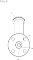
- Fig. 1 is a perspective view showing an external appearance of a check valve 1 according to a first embodiment of the present invention
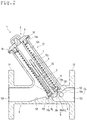
- Fig. 2 is a longitudinal cross-sectional view showing a closed state of the check valve 1 according to the first embodiment.
- a cross section including the axis of a valve shaft 7 is referred to as a longitudinal cross section.
- the check valve 1 is a straight pipe joint type and oblique lift type.
- the check valve 1 includes a valve seat 12a, a moving body 2, a primary flow path (inflow path 12c), and a secondary flow path (outflow path 12d).
- the moving body 2 can linearly reciprocate between a closed state in which it closely contacts with the valve seat 12a and an open state in which it is separated from the valve seat 12a.
- the primary flow path (inflow path 12c) is located on the upstream side of the moving body 2.
- the secondary flow path (outflow path 12d) is located on the downstream side of the moving body 2.
- the moving body 2 includes a valve body 6 supported by a valve seat in a closed state, and a valve shaft 7 extending from the valve body 6.
- the valve seat 12a is formed such that it straddles the center line CL of a connection flow path that extends linearly including the primary flow path (inflow path 12c) and the secondary flow path (outflow path 12d) in a cross section including the center line CL thereon.
- the "straight pipe joint type” is the type of the pipe joint that is connected to other pipes and has the outflow direction on extension of the inflow direction.
- the "oblique lift type” is the type in which the valve body operates obliquely with respect to the straight line connecting the inflow direction and the outflow direction, and the valve body is lifted by the fluid.
- connection parts that connect to other pipes are collar parts 13 and 14 and are flanges, but the present invention is not limited to such a configuration, and the connection parts may be any that can be connected to other pipes.
- the connection parts may be a part formed by a ferrule connection or a part formed by a screw connection.
- valve seat 12a straddles the center line CL
- the center line CL passes through the opening defined by the valve seat 12a, and a part of the valve seat 12a is below the center line CL, and the other part is above the center line CL.
- valve seat 12a may be formed to straddle the center line in any one of cross sections including the center line CL.
- valve seat 12a is formed to straddle the center line CL of the connection flow path. Therefore, when valve body 6 is opened, the fluid can easily flow linearly, and turbulent flow (vortex flow) can be reduced, as compared with the valve seat that is formed not to straddle the center line CL but to be located on one side. This can reduce the pressure loss of the check valve 1 that occurs when the fluid flows therethrough.
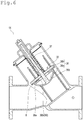
- Fig. 3 is a longitudinal cross-sectional view showing an open state of the check valve 1 according to the first embodiment
- Fig. 4 is a side view of the check valve 1 according to the first embodiment as seen from the inflow path 12c side.
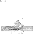
- Fig. 5 is an explanatory diagram which shows a dynamic pressure distribution in the flow path when flowing the fluid into the check valve 1 according to the first embodiment.
- Fig. 3 is a longitudinal cross-sectional view showing an open state of the check valve 1 according to the first embodiment
- Fig. 4 is a side view of the check valve 1 according to the first embodiment as seen from the inflow path 12c side
- Fig. 5 is an explanatory diagram which shows a dynamic pressure distribution in the flow path when flowing the fluid into the check valve 1 according to the first embodiment.
- Fig. 3 is a longitudinal cross-sectional view showing an open state of the check valve 1 according to the first embodiment
- Fig. 4 is a side view of the check valve 1 according to the first embodiment as seen from the inflow path 12c
- FIG. 5 is an explanatory diagram where a valve body upper part 6b, a packing 8, a valve casing 12, a spring body 20 and the like are omitted and other configurations of the check valve 1 are shown in a simplified manner to mainly illustrate the dynamic pressure distribution.
- the check valve 1 is of straight pipe joint type and oblique lift type as described above, and has the moving body 2 including the valve body 6 that linearly and floatingly reciprocates in the direction of approaching or separating from the valve seat 12a.
- the check valve 1 includes the inflow path 12c and the outflow path 12d having the same center line CL.
- the moving body 2 floatingly reciprocates in a direction inclined to the center line CL, specifically, in a direction tilted to the outflow path 12d side.
- the fluid whose backflow is restricted by the check valve 1 is a liquid such as water or a gas such as air.
- the check valve 1 of this embodiment is generally called as a Smolensky type. Therefore, due to the biasing force of the spring body 20, the check valve 1 causes the valve body 6 to come into contact with the valve seat 12a to quickly close the flow path at the moment when the flow of fluid turns into a backflow in which the fluid flows from a secondary side to a primary side. As a result, the check valve 1 can prevent backflow, reduce occurrence of water hammer, and enhance the certainty of the closed state (water stop performance).
- the check valve 1 is not limited to the configuration in which it includes the spring body 20 to press the valve body 6 against the valve seat 12a.
- the configuration may be such that the valve body 6 is pressed against the valve seat 12a by the dead weight of the moving body 2 alone, or by the dead weight of the moving body 2 and the load applied from the damper mechanism by the valve shaft 7 and the guide tube 4 described below.
- the check valve 1 of this embodiment can be used as a generally-called foot valve on the primary side of a lifting pump (not shown in the drawings), so that it can favorably prevent falling of water in the pump pipe due to the high certainty of water stop.
- the check valve 1 is provided in a flow path for passing a liquid or a gas (fluid).
- a predetermined minimum operating pressure such asracking pressure
- the valve body 6 is in the open state to allow the fluid to flow.
- the differential pressure between the primary side and the secondary side of the valve body 6 becomes negative or becomes equal to or lower than a minimum operating pressure, as shown in Fig. 2 , the valve body 6 is in the closed state to block the fluid passing therethrough.
- valve body 6 need not necessarily be configured to be in the fully open state shown in Fig. 3 if a desired amount of area for the fluid passing therethrough can be obtained. Although the valve body 6 is shown in the fully open state in Fig. 3 , the opening degree of the valve body 6 changes depending on the flow rate due to the mass of the moving body 2 and the restoring force of the spring body 20.
- the check valve 1 includes a moving body 2, a valve casing 12, a guide cap 3, and a spring body 20.
- the valve casing 12 accommodates at least a part of the moving body 2 on the opposite side of the valve body 6.
- the guide cap 3 has a guide tube 4 and is attached to the valve casing 12.
- the spring body 20 is provided between the valve body 6 and the guide cap 3 to bias the valve body 6 toward the primary flow path side. That is, the check valve 1 in the present specification refers to the entire pipe joint including the valve body 6 and the like therein.
- a joint part 9 extends substantially linearly to form the inflow path 12c and the outflow path 12d.
- the valve casing 12 according to this embodiment is integrally formed with the joint part 9 by the lost wax manufacturing method, and branches from and intersects with the joint part 9.
- the valve casing 12 and the valve shaft 7 described below extend obliquely toward the outflow path 12d side in a direction intersecting with the flow path direction of the primary flow path (inflow path 12c) and the secondary flow path (outflow path 12d).
- the joint part 9 is integrally formed with a collar part 13 on the upstream side (primary side) and a collar part 14 on the downstream side (secondary side). These collar parts are fixed to pipes (not shown in the drawings) by using tightening tools (not shown in the drawings) such as bolts and nuts.
- the inflow path 12c side of the valve casing 12 (joint part 9) according to this embodiment has a flat mount 15 formed thereon to attach a suction pipe (not shown in the drawings) connected to a suction pump (not shown in the drawings).
- the mount 15 is formed with an opening for decompression 15a that penetrates to the inside of the primary flow path side of the valve casing 12.
- the operator can operate the suction pump to draw the fluid from the suction pipe toward the opening for decompression 15a to make a negative pressure on the upstream side of the valve body 6 to fill with the fluid thereon.
- the operator also can check the pressure state inside the valve casing 12 to check whether the inside of the valve casing 12 is filled with fluid.
- a guide cap 3 described below is removably attached on the termination of the portion in the valve casing 12 that extends in a direction intersecting with the center line CL of the inflow path 12c and the outflow path 12d.
- valve seat 12a is formed so that it straddles the center line CL of the connection flow path connecting the respective connection parts (collar parts 13 and 14) for connecting to the other pipe bodies to be connected, in a cross-sectional view including the center line CL.
- valve seat 12a is formed so that a part of the inner wall of the valve casing 12 projects over the entire circumference toward the flow path side (to narrow the inflow path 12c).
- the seat surface of the valve seat 12a is formed in an annular shape and extends perpendicularly to the reciprocating direction of the moving body 2. That is, the valve seat 12a extends in a direction intersecting with the flow path direction of the inflow path 12c and the outflow path 12d, and the extending direction of the valve shaft 7 and the valve casing 12.
- An annular groove 12h is formed on the outer periphery of the valve seat 12a.
- the annular groove 12h is formed to be recessed toward the inflow path 12c side (the side away from the moving body 2) with respect to the seat surface of the valve seat 12a.
- the annular groove 12h limits the area of the valve seat 12a with which the valve body 6 of the moving body 2 is in contact to enable the valve body 6 to easily closely contact with the valve seat 12a.
- the valve seat 12a extends in a direction intersecting with the flow path direction of the primary flow path (inflow path 12c) and the secondary flow path (outflow path 12d) and the extending direction of the valve shaft 7.
- a downstream-side protruding part 12f that protrudes toward the center line CL is provided in the lower portion of the inner wall surface that forms a secondary flow path (outflow path 12d) on the downstream side of the valve seat 12a.
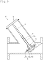
- protruding toward the center line CL side refers to protruding more toward the center line CL side than the main wall surface of the inner wall surface of the joint part 9 (the inner wall surface linearly continuous from the collar parts 13 and 14). That is, as shown in Fig. 9 , though the downstream-side protruding part is formed continuously from the valve seat, it protrudes (from the main wall surface).
- downstream-side protruding part 12f shown in Fig. 2 has a configuration such that the joint part 9 that defines the outflow path 12d has a thicker portion in the lower portion, and the inner wall surface of thicker portion protrudes toward the center line CL.
- the amount of protrusion of the downstream-side protruding part 12f gradually decreases toward the downstream side.
- the flow path cross-sectional area on the downstream side of the valve seat 12a does not locally and sharply change.
- the downstream-side protruding part 12f less protrudes toward the center line CL side of the flow path than the portion close to the center line CL side in the valve seat 12a, and is on extension of this portion in the valve seat 12a. Then, the downstream-side protruding part 12f protrudes toward the inner side of the flow path such that it defines the downstream-side outer periphery of the annular groove 12h, and then it gradually spreads toward the outer peripheral surface side as it further comes toward the downstream side.
- the flow path cross-sectional area of the outflow path 12d in the vicinity of the valve seat 12a is constant or gradually changes toward the downstream side. This can reduce the vortex generation due to the rapid expansion of the flow path cross-sectional area on the secondary side beyond the valve seat 12a.
- an upstream-side protruding part 12i that protrudes toward the center line side is provided in an upper portion of the inner wall surface that forms the primary flow path (inflow path 12c) on the upstream side of the valve seat 12a.
- the upstream-side protruding part 12i protrudes obliquely downward toward the downstream side.
- the amount of protrusion of the upstream-side protruding part 12i gradually increases toward the downstream side.
- the upstream-side protruding part 12i of this embodiment is not provided on the upstream side of the valve seat, and the primary flow path is directed obliquely upward. Therefore, the fluid flowing toward the downstream side through the opening of the valve body meanders significantly.
- a part of the fluid flowing in from the inflow path 12c comes into contact with the upstream-side protruding part 12i, so that the upstream-side protruding part 12i can form an obliquely downward flow.
- This enables the fluid that needs to be directed obliquely upward to push up the valve body 6 by the opening of the valve seat 12a part to flow linearly through the inflow path 12c and the outflow path 12d, and this can reduce the pressure loss.
- the upstream-side protruding part 12i does not protrude up to the center line CL.
- the upstream-side protruding part 12i according to this embodiment protrudes from the upper wall surface by 1/3 (including approximately 1/3) of the inflow side flow path width.
- a part of the fluid can easily flow linearly from the inflow path 12c along the center line CL, and the pressure loss can be reduced.
- the moving body 2 reciprocates inside the valve casing 12 to move the valve body 6 close to and away from the valve seat 12a between the primary flow path and the secondary flow path. Thereby, the moving body 2 prevents the backflow while adjusting the opening amount of the valve body 6 according to the flow rate.
- the moving body 2 is mainly configured with a valve shaft 7, a valve body 6, and a water stop part (packing 8).
- the valve shaft 7 extends in the reciprocation direction.
- the valve body 6 is provided at the lower side end of the valve shaft 7.
- the water stop portion (packing 8) is attached to the valve body 6 that is in contact with the valve seat 12a in the closed state.
- valve shaft 7 is accommodated in the guide tube 4 described below to reciprocate the moving body 2 so that the moving body 2 does not deviate in the direction perpendicular to the axial direction of the valve shaft 7.
- the valve shaft 7 is formed in a rod shape and continuously extends from the central portion of the upper surface of the valve body 6.
- valve body 6 and the valve shaft 7 are made of stainless steel, but may be made of a corrosion-resistant synthetic resin material such as polyvinyl chloride.
- the spring body 20 mounted around the valve shaft 7 elastically biases the upper surface of the valve body 6 (valve body upper part 6b).
- the valve body 6 includes a valve body lower part 6a and a valve body upper part 6b.
- the valve body upper part 6b extends in a direction intersecting with the flow path direction of the inflow path 12c and the outflow path 12d and the extending direction of the valve shaft 7 and the valve casing 12.
- the valve body upper part 6b has a collar 6c that is larger in the radial direction than the valve body lower part 6a with the valve shaft 7 in the center.
- the end of the valve body upper part 6b itself is the collar 6c.
- the lower end of the collar 6c is below the center line CL in the closed state shown in Fig. 3 , and moves to a position above the center line CL at a certain position in the open state shown in Fig. 2 .
- the collar 6c moves to a position above the center line CL when the position changes from the closed state to a certain position in the open state. As a result, the amount of fluid that flows linearly can be increased.
- the lower end of the packing 8 described below is located below the lower end of the collar 6c.
- valve body upper part 6b is in sliding contact with the inner wall 12b of the valve casing 12 to have a function of guiding the movement of the moving body 2, so that the lower end side of the moving body 2 does not deviate in the direction perpendicular to the axial direction of the valve shaft 7.
- the end of the valve body upper part 6b on the side of the inflow path 12c is arranged to be capable of sliding contact with the inner wall 12b of the valve casing 12 when the valve body 6 is opened.
- the inner wall 12b of the valve casing 12 with which the valve body upper part 6b is in sliding contact is not limited to the flat one, and also includes the one having a rib-shaped one such as a guide rib 12g protruding from the surroundings, which is added thereon, in a part of the inner wall 12b.
- valve body upper part 6b is arranged to be capable of sliding contact with the four guide ribs 12g that protrude into the valve casing 12 and extend along the longitudinal direction of the valve casing 12.
- the end of the valve body upper part 6b on the side of the inflow path 12c is arranged to be capable of sliding contact with the inner wall 12b of the valve casing 12. Thereby, the deviation of the valve body upper part 6b can be reduced by the valve casing 12.
- valve body upper part 6b is pushed by a nut 11 on the upper surface to have a function as a washer that evenly supports the packing 8 in the plane direction between the valve body lower part 6a.
- An insertion hole 6g through which the valve shaft 7 is inserted is formed at the center of the valve body upper part 6b, and penetrates in the thickness direction of the valve body upper part 6b.
- the valve body lower part 6a includes a planar upper surface having the valve shaft 7 continuously formed in the central portion thereof and the other surface having a partial spherical shape.
- valve body lower part 6a has a partial spherical surface on the outer surface facing the flow path.
- the partial spherical surface of the valve body lower part 6a is disposed at a position where the fluid flowing linearly in the flow path direction from the inflow path 12c comes into contact with the partial spherical surface.
- valve body 6 valve body lower part 6a
- moving body 2 valve body 6
- the fluid flows through the check valve 1 while the fluid is in contact with the partial spherical surface side of the valve body lower part 6a.
- This allows the valve body 36 to less obstruct the flow of the fluid, and the velocity of the fluid to be less reduced. Therefore, the fluid can pass therethrough with a low head loss (friction resistance).
- valve shaft 7 and the valve body lower part 6a, and the valve body upper part 6b are configured by assembling separate members.
- the configuration is not limited to this. If the packing 8 is flexible and can be attached to the valve body 6 by deforming the packing 8, the valve body lower part 6a and the valve body upper part 6b do not necessarily have to be configured with separate members.
- the water stop part (packing 8) is a member that is pressed by the valve body 6 (valve body upper part 6b) and the valve seat 12a in the closed state of the check valve 1 to stop water at the valve seat 12a, and is disposed between the valve body lower part 6a and the valve body upper part 6b (collar 6c).
- the packing 8 is formed in an annular shape having a central hole penetrating through the thickness direction. Specifically, the packing 8 has the central hole passed through the valve shaft 7, and is disposed between the valve body lower part 6a and the valve body upper part 6b.
- a part of the packing 8 is below the center line CL when it is in the closed state shown in Fig. 3 , and the entire packing 8 moves above the center line CL at a certain position in the open state shown in Fig. 2 .
- change from the closed state to a certain position in the open state allows the packing 8 to less obstruct the flow passing through the center line CL to reduce the pressure loss.
- a certain position in the open state is preferably a position where the valve body 6 is in an open state at a standard flow rate.
- this position is a position in which the check valve 1 (valve body 6) is open at 70% with respect to the fully open state (70% of the maximum opening degree of the check valve 1).
- Such a configuration allows the packing 8 at a standard flow rate to less obstruct the flow in the vicinity of the center line CL at which the flow speed is the fastest to prevent the pressure loss from increasing.
- the check valve 1 further includes the nut 11 that presses the valve body upper part 6b from the other side (upper side) toward the valve body lower part 6a side.
- the nut 11 has an elastically deformable friction ring to have a loosening prevention function.
- the nut 11 only needs to have a loosening prevention function and is not limited to the one having a friction ring.
- it may be configured with a double nut (not shown in the drawings).
- one of the double nuts may have a wedge-shaped projection, and the other nut may be formed with a groove having a corresponding shape to receive the projection.
- the guide cap 3 is removably attached to the valve casing 12 to seal the upper side of the valve body 6 and to guide the reciprocating movement of the moving body 2.
- the guide cap 3 is configured with a guide tube 4 and a disk-shaped top plate part 5 integrally formed on the upper end of the guide tube 4.
- the top plate part 5 has a ferrule flange 5e shown in Fig. 2 at its edge and is removably fastened to the ferrule flange 5e by a ferrule joint (not shown in the drawings) such that the gasket 16 is sandwiched between the ferrule flange 12e formed on the upper end of the valve casing 12.
- a guide tube 4 is provided obliquely downward (on the primary flow path side) substantially at the center of the top plate part 5.
- the guide tube 4 guides the sliding of the valve shaft 7 of the valve body 6 on its inner surface, extends from the top plate part 5 obliquely downward to the valve seat 12a side to guide the valve shaft 7 connected to the valve body 6 to enable the valve body 6 to reciprocate.
- FIG. 5 is an explanatory diagram showing a dynamic pressure distribution in the flow path when a fluid is caused to flow through the check valve 1 according to the first embodiment, and showing the flow of fluid and dynamic pressure distribution at a flow velocity of about 4 m/s on the inflow side and a flow rate of about 4800 L/min (valve opening degree: 50%).
- a flow velocity of about 4 m/s on the inflow side
- a flow rate of about 4800 L/min (valve opening degree: 50%).
- the main flow with high dynamic pressure (dynamic pressure DP1) extends substantially parallel to the flow path direction without going to the bottom side of the flow path. Further, it can be seen that the vortex W induced by the main flow does not encroach to the center side of the flow path, and its range is small. Therefore, the diffusion and separation of the fluid was small, the head loss was about 2.8 m, and the pressure loss can be reduced to a small level.
- a check valve 1X according to a second embodiment is described below mainly with reference to Fig. 6 .
- the check valve 1X is installed to a pipe having a larger diameter than the check valve 1.
- Fig. 6 is a longitudinal cross-sectional view showing an open state of the check valve 1X according to the second embodiment.
- the check valve 1X includes a moving body 32.
- the moving body 32 includes a valve shaft 37 and a valve body 36 integrally formed with a lower end of the valve shaft 37.
- the valve body 36 includes a valve body lower part 36a and a valve body upper part 36b.
- the valve body lower part 36a is formed in a partial spherical shape having a hollow part 36d.
- valve body lower part 36a has a partial spherical surface on the outer surface on the side facing the flow path, and has a shape symmetrical with respect to the center line CL, and is disposed inside the check valve 1.
- the valve body lower part 36a has the hollow part 36d, which favorably improves the responsiveness to changes in the flow rate. At the same time, it is formed in a partial spherical shape, which can reduce the flow resistance and the pressure loss.
- the valve body lower part 36a include a small diameter part 36h having an annular shape at a portion in contact with the valve body upper part 36b.
- An opening 36i connected to the hollow part 36d is formed in the small diameter part 36h.
- the packing 8 is fitted in a recess 36e formed ontside the outer periphery of the small diameter part 36h, and between the valve body upper part 36b and the valve body lower part 36a.
- the recess 36e is formed by overlapping of a lower surface of the valve body upper part 36b and a portion having an L-shaped cross section.
- the L-shaped cross section is formed by a part of the upper surface of the valve body lower part 36a, in which the part of the upper surface is continuous from the peripheral surface of the small diameter part 36h.
- the maximum diameter of the hollow part 36d is formed to be larger than that of the opening 36i.
- the hollow part 36d is formed in the valve body lower part 36a, so that the weight of the moving body 32 can be reduced.
- the valve body 36 including the hollow part 36d is formed in mirror symmetry with respect to an imaginary plane that includes the axial directions of the flow path direction and the valve shaft 37 therein. With this formation, when the fluid flows in the flow path direction, it is possible to prevent the valve body 36 from being deviated by the force applied from the fluid to the valve body 36, and to stabilize the flow of the fluid.
- Fig. 7 is a longitudinal cross-sectional view showing an open state of the check valve 1Y according to the third embodiment
- Fig. 8 is a perspective view showing a moving body 52 according to the third embodiment.
- the description of the configuration common to the check valve 1 according to the first embodiment or the check valve 1X according to the second embodiment will not be repeated.
- the guide cap according to the check valve 1Y is common to that of the first and second embodiments except for the size, so the description thereof will not be repeated.
- the check valve 1Y mainly includes a moving body 52 and a valve casing 62 that houses the moving body 52.
- the moving body 52 is mainly configured with a round rod-shaped valve shaft 57 extending in the reciprocation direction, a valve body 56 provided at a lower side end of the valve shaft 57, and a packing 8 attached to the valve body 56.
- the valve body 56 is configured with a valve body lower part 56a integrally formed at the lower side (primary flow path side) end of the valve shaft 57 and a valve body upper part 56b mounted on the valve body lower part 56a.
- the valve body lower part 56a has an outer surface formed in a partial spherical surface, and has two flat surface parts 56f at positions apart by 180 degrees from each other with the axial in the center.
- the two flat surface parts 56f rise in parallel to reciprocating direction of the moving body 52, and extends parallel to each other.
- the two flat surface parts 56f provided can increase the area of an edge part 56k described below as compared with that without the flat surface parts 56f. This can increase the load of the fluid that pushes up the valve body 56 as compared with that of the fluid that pushes up the spherical part, and can make the beginning of the flow of fluid smooth.
- a female screw part is formed at the center of the valve body lower part 56a, and is threadedly engaged with a male screw part formed at the lower end of the valve shaft 57.
- valve body 56 rotates together with the valve shaft when the fluid flows into the check valve 1Y and pushes the moving body 52 upward to flow to the downstream side.
- the flat surface part 56f receives the dynamic pressure of the fluid, and the posture of the moving body 52 is automatically adjusted into the direction parallel to the flow path direction. In this way, the pressure loss of the valve body 56 is reduced.
- the valve body lower part 56a has a facing part 56j and an edge part 56k.
- the facing part 56j is formed at a position where a part of the facing part 56j faces a small diameter part 56h of the valve body upper part 56b.
- the edge part 56k is formed radially outward of the facing part 56j and clamps a packing 8 between the valve body lower part 56a and the valve body upper part 56b.
- a hollow part 56d and an opening 56i that is connected to the hollow part 56d and faces the valve body upper part 56b are formed in the valve body lower part 56a.
- the facing part 56j defines the upper portion of the hollow part 56d on the radially outward of the valve body lower part 56a.
- the above opening 56i is formed in the central part in the radial direction of the facing part 56j .
- the edge part 56k has a function of clamping the packing 8 between the edge part 56k and the valve body upper part 56b, and is formed thicker than the facing part 56j. In this way, the edge part 56k is formed thicker than the facing part 56j. This can increase the volume of the hollow part 56d while stably holding the packing 8 to which a repeated impact load is applied from the valve seat 62a provided in the valve casing 62 by repeated opening and closing of the valve body 56.
- a spring seat surface 56e recessed downward (primary flow path side) from a radially outward portion is formed on a radially inward portion in the other side surface (upper surface) of the valve body upper part 56b.
- Fig. 9 is a schematic longitudinal cross-sectional view showing a closed state of the check valve 1Z according to the fourth embodiment.
- the spring body 20 is not shown.
- the valve shaft 77 included in the check valve 1Z according to this embodiment has a hollow space 77a and is formed in a tubular shape.
- the valve shaft 77 is guided by a guide rod 74 inserted into a hollow space 77a in the valve shaft 77 to be capable of reciprocating. That is, the valve shaft 77 slides on the outer surface of the guide rod 74 with the inner surface facing the hollow space 77a to be guided in the reciprocating direction by the guide rod 74.
- valve shaft 77 is guided by the guide rod 74, so that a valve body 76 connected to the valve shaft 77 is guided in the reciprocating direction.
- a hollow part 76d that is continuous with the hollow space 77a of the valve shaft 77 is formed inside the valve body 76 according to this embodiment.
- the hollow space 77a of the valve shaft 77 and the hollow part 76d of the valve body 76 are continuously formed, so that the moving body 72 including the valve shaft 77 and the valve body 76 can be reduced in weight, and the responsiveness to changes in the flow rate can be improved.
- the check valve of the present invention and the various components of the reciprocating member configuring the check valve need not be independent of each other. There may be allowable cases such that a plurality of components is formed as a single member, one component is formed out of a plurality of members, one component is a part of another component, or a part of one component overlaps with a part of another component.
- This embodiment includes the following technical ideas.
Landscapes
- Engineering & Computer Science (AREA)
- General Engineering & Computer Science (AREA)
- Mechanical Engineering (AREA)
- Check Valves (AREA)
Applications Claiming Priority (1)
| Application Number | Priority Date | Filing Date | Title |
|---|---|---|---|
| PCT/JP2020/003755 WO2021152842A1 (ja) | 2020-01-31 | 2020-01-31 | 逆止弁 |
Publications (2)
| Publication Number | Publication Date |
|---|---|
| EP3889480A1 true EP3889480A1 (de) | 2021-10-06 |
| EP3889480A4 EP3889480A4 (de) | 2022-10-05 |
Family
ID=77062635
Family Applications (1)
| Application Number | Title | Priority Date | Filing Date |
|---|---|---|---|
| EP20786426.5A Pending EP3889480A4 (de) | 2020-01-31 | 2020-01-31 | Rückschlagventil |
Country Status (10)
| Country | Link |
|---|---|
| US (1) | US11828373B2 (de) |
| EP (1) | EP3889480A4 (de) |
| JP (1) | JP7068500B2 (de) |
| KR (1) | KR20210098840A (de) |
| CN (1) | CN113474584A (de) |
| CA (1) | CA3097290C (de) |
| MX (1) | MX2020011430A (de) |
| PH (1) | PH12020551954A1 (de) |
| SG (1) | SG11202011867SA (de) |
| WO (1) | WO2021152842A1 (de) |
Families Citing this family (1)
| Publication number | Priority date | Publication date | Assignee | Title |
|---|---|---|---|---|
| CN113883308B (zh) * | 2021-11-04 | 2024-06-04 | 杭州老板电器股份有限公司 | 吸油烟机系统 |
Family Cites Families (50)
| Publication number | Priority date | Publication date | Assignee | Title |
|---|---|---|---|---|
| US862714A (en) | 1906-10-22 | 1907-08-06 | Boris V Constantinov | Valve. |
| US1703248A (en) * | 1926-02-17 | 1929-02-26 | George E R Rothenbucher | Check valve |
| US2447729A (en) * | 1945-05-05 | 1948-08-24 | Bertea Alex | Check valve |
| US2619115A (en) | 1947-03-22 | 1952-11-25 | John A Dondero | Spring biased relief valve |
| US6142037A (en) * | 1999-06-23 | 2000-11-07 | Daimlerchrysler Corporation | Transmission check valve |
| US6929238B2 (en) | 2000-02-18 | 2005-08-16 | Ga Industries Inc. | Electric motor actuated stop and self-closing check valve |
| JP2002213629A (ja) * | 2001-01-19 | 2002-07-31 | Nippo Valve Co Ltd | 減圧式逆流防止装置 |
| IL156425A0 (en) * | 2001-10-29 | 2004-01-04 | Bermad Fa | Roll diaphragm control valve |
| AU2003282978A1 (en) * | 2002-10-18 | 2004-05-04 | Watts Regulator Co. | Spill-resistant relief valve |
| KR100538067B1 (ko) | 2003-12-19 | 2005-12-20 | 매그나칩 반도체 유한회사 | 이미지센서의 제조방법 |
| KR100624758B1 (ko) * | 2005-03-02 | 2006-10-30 | 차도균 | 온수개폐밸브용 카트리지 |
| SE532347C2 (sv) | 2007-07-09 | 2009-12-22 | Itt Mfg Enterprises Inc | Backventil |
| IT1391673B1 (it) * | 2008-08-18 | 2012-01-17 | Carel S P A | Struttura di valvola di regolazione perfezionata, particolarmente per la regolazione del flusso di fluidi in impianti frigoriferi |
| US8596301B2 (en) * | 2008-10-01 | 2013-12-03 | Marshall Excelsior Company | Valve assembly |
| KR20110073954A (ko) | 2009-12-24 | 2011-06-30 | 주식회사 에이제이에스 | 체크밸브 |
| CN201875146U (zh) * | 2010-07-21 | 2011-06-22 | 中核苏阀科技实业股份有限公司 | 大口径高温高压截止阀 |
| CN102003556B (zh) * | 2010-11-13 | 2012-10-10 | 宣达实业集团有限公司 | 活塞式防水击高压平衡止回阀 |
| CN102537435B (zh) | 2012-02-27 | 2013-09-18 | 宁波华成阀门有限公司 | 防虹吸倒流先导式电磁阀 |
| US9816622B2 (en) | 2012-05-31 | 2017-11-14 | Ishizaki Corporation | Check valve and pumping system |
| CN202732990U (zh) * | 2012-08-09 | 2013-02-13 | 浙江曼尔达水控有限公司 | 一种暖气阀 |
| CN202790588U (zh) * | 2012-09-19 | 2013-03-13 | 浙江工贸职业技术学院 | 缓冲式防水锤阀 |
| CN202927064U (zh) * | 2012-11-10 | 2013-05-08 | 无锡智能自控工程股份有限公司 | 一种波纹管y型直通夹套气相阀 |
| CN102927294B (zh) * | 2012-11-10 | 2014-02-12 | 无锡智能自控工程股份有限公司 | 一种波纹管y型直通夹套气相阀 |
| CN203051863U (zh) * | 2013-01-07 | 2013-07-10 | 程汉章 | 一种平衡阀 |
| CN203784328U (zh) * | 2013-11-20 | 2014-08-20 | 无锡智能自控工程股份有限公司 | 一种调节阀阀杆新型定位结构 |
| CN103759050A (zh) * | 2014-01-17 | 2014-04-30 | 哈电集团哈尔滨电站阀门有限公司 | 新型受控关闭止回阀 |
| CN203836293U (zh) * | 2014-01-17 | 2014-09-17 | 哈电集团哈尔滨电站阀门有限公司 | 新型受控关闭止回阀 |
| CN104976390A (zh) * | 2014-04-10 | 2015-10-14 | 苏州科迪流体控制设备有限公司 | 一种新型升降式止回阀 |
| JP5724114B1 (ja) * | 2014-09-24 | 2015-05-27 | アック東北株式会社 | 多機能吐出管又は多機能バルフ゛及びポンプ施設 |
| JP6496514B2 (ja) * | 2014-10-07 | 2019-04-03 | 株式会社イシザキ | 逆止弁および逆止弁用封止体 |
| CN204664420U (zh) * | 2015-01-24 | 2015-09-23 | 浙江华大阀门有限公司 | 一种高温高压y型截止阀 |
| JP6056067B2 (ja) * | 2015-04-08 | 2017-01-11 | アック東北株式会社 | 仕切弁及び急閉式逆止弁と、緩閉式副弁及び負圧時作動空気吸気弁を有するウォーターハンマー防止機能とを有する多機能バルブ。 |
| JP6752043B2 (ja) * | 2015-04-17 | 2020-09-09 | 旭有機材株式会社 | 逆止弁 |
| CN204729687U (zh) | 2015-07-04 | 2015-10-28 | 方正阀门集团(温州)机械制造有限公司 | 升降式止回阀 |
| CN205064949U (zh) | 2015-10-16 | 2016-03-02 | 甘肃中核嘉华核设备制造有限公司 | 一种y型直通升降式止回阀 |
| CN205534261U (zh) * | 2016-02-25 | 2016-08-31 | 南华大学 | 螺旋式节水水龙头 |
| CN205715700U (zh) * | 2016-03-31 | 2016-11-23 | 江苏双虎环保节能设备科技有限公司 | 一种转角截止阀 |
| CN205715715U (zh) * | 2016-03-31 | 2016-11-23 | 江苏双虎环保节能设备科技有限公司 | 一种阀芯组件 |
| CN205715698U (zh) * | 2016-03-31 | 2016-11-23 | 江苏双虎环保节能设备科技有限公司 | 一种截止阀 |
| CN205859187U (zh) * | 2016-08-04 | 2017-01-04 | 汉威阀门有限公司 | 阀芯 |
| CN206496001U (zh) * | 2016-08-31 | 2017-09-15 | 浙江智鹏自控阀门有限公司 | 衬氟波纹管调节阀 |
| CN206017788U (zh) * | 2016-08-31 | 2017-03-15 | 浙江智鹏自控阀门有限公司 | 氯气紧急切断阀 |
| CN206723474U (zh) * | 2017-04-19 | 2017-12-08 | 沈剑 | 一种农用节水阀 |
| CN109751438A (zh) * | 2017-11-03 | 2019-05-14 | 中核苏阀科技实业股份有限公司 | 一种高压内置斜瓣式止回阀 |
| CN107859781A (zh) * | 2017-12-06 | 2018-03-30 | 凯瑞特阀业有限公司 | 截止阀 |
| CN207848441U (zh) * | 2018-01-19 | 2018-09-11 | 浙江金锋自动化仪表有限公司 | 先导式泄压阀 |
| ES2924634T3 (es) | 2018-03-12 | 2022-10-10 | Ishizaki Co Ltd | Válvula de retención y cuerpo oscilante para válvula de retención |
| CN209067863U (zh) * | 2018-11-30 | 2019-07-05 | 苏州德兰能源科技股份有限公司 | 一种熔盐阀防积淀阀芯结构 |
| US11940052B2 (en) * | 2018-12-06 | 2024-03-26 | Hayward Industries, Inc. | Flow control valve for suction cleaners |
| CN209458430U (zh) * | 2018-12-17 | 2019-10-01 | 艾碧匹(上海)流体控制有限公司 | 一种带有止逆功能的溢流阀 |
-
2020
- 2020-01-31 JP JP2020560843A patent/JP7068500B2/ja active Active
- 2020-01-31 CN CN202080003071.0A patent/CN113474584A/zh active Pending
- 2020-01-31 KR KR1020207031261A patent/KR20210098840A/ko not_active Application Discontinuation
- 2020-01-31 SG SG11202011867SA patent/SG11202011867SA/en unknown
- 2020-01-31 WO PCT/JP2020/003755 patent/WO2021152842A1/ja unknown
- 2020-01-31 EP EP20786426.5A patent/EP3889480A4/de active Pending
- 2020-01-31 MX MX2020011430A patent/MX2020011430A/es unknown
- 2020-01-31 CA CA3097290A patent/CA3097290C/en active Active
- 2020-01-31 US US17/058,753 patent/US11828373B2/en active Active
- 2020-11-16 PH PH12020551954A patent/PH12020551954A1/en unknown
Also Published As
| Publication number | Publication date |
|---|---|
| CN113474584A (zh) | 2021-10-01 |
| KR20210098840A (ko) | 2021-08-11 |
| SG11202011867SA (en) | 2021-09-29 |
| US11828373B2 (en) | 2023-11-28 |
| JP7068500B2 (ja) | 2022-05-16 |
| EP3889480A4 (de) | 2022-10-05 |
| CA3097290A1 (en) | 2021-07-31 |
| MX2020011430A (es) | 2021-08-24 |
| PH12020551954A1 (en) | 2021-08-16 |
| US20220316612A1 (en) | 2022-10-06 |
| WO2021152842A1 (ja) | 2021-08-05 |
| JPWO2021152842A1 (de) | 2021-08-05 |
| CA3097290C (en) | 2023-08-29 |
Similar Documents
| Publication | Publication Date | Title |
|---|---|---|
| CN103097785B (zh) | 用于流体阀的阀座装置 | |
| US10907743B2 (en) | Check valve and reciprocating body for check valve | |
| US7175157B2 (en) | Fluid controller | |
| US10738901B1 (en) | Check valve | |
| EP3889480A1 (de) | Rückschlagventil | |
| KR102406046B1 (ko) | 고압 밸브 | |
| GB2433102A (en) | Valve | |
| US11781666B2 (en) | Control valve | |
| US10767788B2 (en) | Valve body having primary and secondary stem guides | |
| US11353114B1 (en) | Control valve | |
| WO2022191239A1 (ja) | 逆止弁 | |
| US11287057B2 (en) | Y-globe valve assembly with integrated pressure relief passageway | |
| TWI761761B (zh) | 止回閥 | |
| US10794505B2 (en) | Spring seat for an internal valve | |
| RU2572031C2 (ru) | Задвижка | |
| RU2572032C2 (ru) | Затвор клиновой задвижки | |
| RU2572030C2 (ru) | Затвор клиновой задвижки и способ его сборки | |
| CN110925471A (zh) | 一种低温截止阀 |
Legal Events
| Date | Code | Title | Description |
|---|---|---|---|
| STAA | Information on the status of an ep patent application or granted ep patent |
Free format text: STATUS: UNKNOWN |
|
| STAA | Information on the status of an ep patent application or granted ep patent |
Free format text: STATUS: THE INTERNATIONAL PUBLICATION HAS BEEN MADE |
|
| PUAI | Public reference made under article 153(3) epc to a published international application that has entered the european phase |
Free format text: ORIGINAL CODE: 0009012 |
|
| STAA | Information on the status of an ep patent application or granted ep patent |
Free format text: STATUS: REQUEST FOR EXAMINATION WAS MADE |
|
| 17P | Request for examination filed |
Effective date: 20201016 |
|
| AK | Designated contracting states |
Kind code of ref document: A1 Designated state(s): AL AT BE BG CH CY CZ DE DK EE ES FI FR GB GR HR HU IE IS IT LI LT LU LV MC MK MT NL NO PL PT RO RS SE SI SK SM TR |
|
| A4 | Supplementary search report drawn up and despatched |
Effective date: 20220902 |
|
| RIC1 | Information provided on ipc code assigned before grant |
Ipc: F16K 27/02 20060101ALI20220829BHEP Ipc: F16K 15/06 20060101AFI20220829BHEP |
|
| DAV | Request for validation of the european patent (deleted) | ||
| DAX | Request for extension of the european patent (deleted) | ||
| STAA | Information on the status of an ep patent application or granted ep patent |
Free format text: STATUS: EXAMINATION IS IN PROGRESS |
|
| 17Q | First examination report despatched |
Effective date: 20240627 |