EP3889455B1 - Bremsscheibe - Google Patents
Bremsscheibe Download PDFInfo
- Publication number
- EP3889455B1 EP3889455B1 EP21161759.2A EP21161759A EP3889455B1 EP 3889455 B1 EP3889455 B1 EP 3889455B1 EP 21161759 A EP21161759 A EP 21161759A EP 3889455 B1 EP3889455 B1 EP 3889455B1
- Authority
- EP
- European Patent Office
- Prior art keywords
- component
- brake disc
- brake
- connecting elements
- relative
- Prior art date
- Legal status (The legal status is an assumption and is not a legal conclusion. Google has not performed a legal analysis and makes no representation as to the accuracy of the status listed.)
- Active
Links
Images

Classifications
-
- F—MECHANICAL ENGINEERING; LIGHTING; HEATING; WEAPONS; BLASTING
- F16—ENGINEERING ELEMENTS AND UNITS; GENERAL MEASURES FOR PRODUCING AND MAINTAINING EFFECTIVE FUNCTIONING OF MACHINES OR INSTALLATIONS; THERMAL INSULATION IN GENERAL
- F16D—COUPLINGS FOR TRANSMITTING ROTATION; CLUTCHES; BRAKES
- F16D65/00—Parts or details
- F16D65/02—Braking members; Mounting thereof
- F16D65/12—Discs; Drums for disc brakes
- F16D65/123—Discs; Drums for disc brakes comprising an annular disc secured to a hub member; Discs characterised by means for mounting
-
- F—MECHANICAL ENGINEERING; LIGHTING; HEATING; WEAPONS; BLASTING
- F16—ENGINEERING ELEMENTS AND UNITS; GENERAL MEASURES FOR PRODUCING AND MAINTAINING EFFECTIVE FUNCTIONING OF MACHINES OR INSTALLATIONS; THERMAL INSULATION IN GENERAL
- F16D—COUPLINGS FOR TRANSMITTING ROTATION; CLUTCHES; BRAKES
- F16D65/00—Parts or details
- F16D65/02—Braking members; Mounting thereof
- F16D2065/13—Parts or details of discs or drums
- F16D2065/1304—Structure
-
- F—MECHANICAL ENGINEERING; LIGHTING; HEATING; WEAPONS; BLASTING
- F16—ENGINEERING ELEMENTS AND UNITS; GENERAL MEASURES FOR PRODUCING AND MAINTAINING EFFECTIVE FUNCTIONING OF MACHINES OR INSTALLATIONS; THERMAL INSULATION IN GENERAL
- F16D—COUPLINGS FOR TRANSMITTING ROTATION; CLUTCHES; BRAKES
- F16D65/00—Parts or details
- F16D65/02—Braking members; Mounting thereof
- F16D2065/13—Parts or details of discs or drums
- F16D2065/1304—Structure
- F16D2065/1316—Structure radially segmented
-
- F—MECHANICAL ENGINEERING; LIGHTING; HEATING; WEAPONS; BLASTING
- F16—ENGINEERING ELEMENTS AND UNITS; GENERAL MEASURES FOR PRODUCING AND MAINTAINING EFFECTIVE FUNCTIONING OF MACHINES OR INSTALLATIONS; THERMAL INSULATION IN GENERAL
- F16D—COUPLINGS FOR TRANSMITTING ROTATION; CLUTCHES; BRAKES
- F16D65/00—Parts or details
- F16D65/02—Braking members; Mounting thereof
- F16D2065/13—Parts or details of discs or drums
- F16D2065/134—Connection
-
- F—MECHANICAL ENGINEERING; LIGHTING; HEATING; WEAPONS; BLASTING
- F16—ENGINEERING ELEMENTS AND UNITS; GENERAL MEASURES FOR PRODUCING AND MAINTAINING EFFECTIVE FUNCTIONING OF MACHINES OR INSTALLATIONS; THERMAL INSULATION IN GENERAL
- F16D—COUPLINGS FOR TRANSMITTING ROTATION; CLUTCHES; BRAKES
- F16D65/00—Parts or details
- F16D65/02—Braking members; Mounting thereof
- F16D2065/13—Parts or details of discs or drums
- F16D2065/134—Connection
- F16D2065/1348—Connection resilient
-
- F—MECHANICAL ENGINEERING; LIGHTING; HEATING; WEAPONS; BLASTING
- F16—ENGINEERING ELEMENTS AND UNITS; GENERAL MEASURES FOR PRODUCING AND MAINTAINING EFFECTIVE FUNCTIONING OF MACHINES OR INSTALLATIONS; THERMAL INSULATION IN GENERAL
- F16D—COUPLINGS FOR TRANSMITTING ROTATION; CLUTCHES; BRAKES
- F16D65/00—Parts or details
- F16D65/02—Braking members; Mounting thereof
- F16D2065/13—Parts or details of discs or drums
- F16D2065/134—Connection
- F16D2065/1356—Connection interlocking
- F16D2065/136—Connection interlocking with relative movement radially
-
- F—MECHANICAL ENGINEERING; LIGHTING; HEATING; WEAPONS; BLASTING
- F16—ENGINEERING ELEMENTS AND UNITS; GENERAL MEASURES FOR PRODUCING AND MAINTAINING EFFECTIVE FUNCTIONING OF MACHINES OR INSTALLATIONS; THERMAL INSULATION IN GENERAL
- F16D—COUPLINGS FOR TRANSMITTING ROTATION; CLUTCHES; BRAKES
- F16D65/00—Parts or details
- F16D65/02—Braking members; Mounting thereof
- F16D2065/13—Parts or details of discs or drums
- F16D2065/134—Connection
- F16D2065/1356—Connection interlocking
- F16D2065/1364—Connection interlocking with relative movement axially
-
- F—MECHANICAL ENGINEERING; LIGHTING; HEATING; WEAPONS; BLASTING
- F16—ENGINEERING ELEMENTS AND UNITS; GENERAL MEASURES FOR PRODUCING AND MAINTAINING EFFECTIVE FUNCTIONING OF MACHINES OR INSTALLATIONS; THERMAL INSULATION IN GENERAL
- F16D—COUPLINGS FOR TRANSMITTING ROTATION; CLUTCHES; BRAKES
- F16D65/00—Parts or details
- F16D65/02—Braking members; Mounting thereof
- F16D2065/13—Parts or details of discs or drums
- F16D2065/134—Connection
- F16D2065/1356—Connection interlocking
- F16D2065/1368—Connection interlocking with relative movement both radially and axially
-
- F—MECHANICAL ENGINEERING; LIGHTING; HEATING; WEAPONS; BLASTING
- F16—ENGINEERING ELEMENTS AND UNITS; GENERAL MEASURES FOR PRODUCING AND MAINTAINING EFFECTIVE FUNCTIONING OF MACHINES OR INSTALLATIONS; THERMAL INSULATION IN GENERAL
- F16D—COUPLINGS FOR TRANSMITTING ROTATION; CLUTCHES; BRAKES
- F16D65/00—Parts or details
- F16D65/02—Braking members; Mounting thereof
- F16D2065/13—Parts or details of discs or drums
- F16D2065/134—Connection
- F16D2065/1384—Connection to wheel hub
-
- F—MECHANICAL ENGINEERING; LIGHTING; HEATING; WEAPONS; BLASTING
- F16—ENGINEERING ELEMENTS AND UNITS; GENERAL MEASURES FOR PRODUCING AND MAINTAINING EFFECTIVE FUNCTIONING OF MACHINES OR INSTALLATIONS; THERMAL INSULATION IN GENERAL
- F16D—COUPLINGS FOR TRANSMITTING ROTATION; CLUTCHES; BRAKES
- F16D65/00—Parts or details
- F16D65/02—Braking members; Mounting thereof
- F16D2065/13—Parts or details of discs or drums
- F16D2065/134—Connection
- F16D2065/1392—Connection elements
Definitions
- This invention relates to a brake disc.
- the brake disc according to this invention is preferably for use by bicycles or motorcycles with two or more wheels, without thereby limiting the scope of the invention.
- brake discs of this type are known from the US2013/133996A1 , US2017/198774A1 as well from the US2017/114846A1 .
- the brake strip of a brake disc is subjected to a high level of heating during braking and is particularly sensitive to thermal expansion due to its thickness, which is to be considered reduced in relation to the considerable extension of its surface.
- This heating may induce deformations of the brake strip both in the diametric direction and in the axial direction of the disc, creating considerable problems in the mechanics of the braking.
- a brake disc rotating about its own axis of rotation, comprising a brake strip, an element for supporting the brake strip and a plurality of first elements for connecting the brake strip with the supporting element, which can be elastically deformed in such a way as to allow a relative movement of the brake strip with respect to the supporting element.
- the supporting element comprises at least a first component, designed to be connected to a hub of a rotary element, and at least a second component connected to the brake strip by means of the first connecting elements.
- a plurality of second connecting elements of the first component and of the second component are elastically deformable in such a way as to allow a relative movement between the first component and the second component.
- the elastic connections are divided into at least two groups connected in series, the compliance of the connections is doubled in a radial direction and quadrupled in a direction parallel to the axis of rotation, under equal conditions of compliance of all the elastic connections.
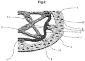
- the numeral 1 denotes a brake disc according to the invention.
- the brake disc 1 rotates about its axis of rotation 1a.
- the brake disc 1 comprises a brake strip 2.
- the brake strip 2 of the brake disc 1 is an annular strip having a thickness defined by the distance between end faces, preferably parallel, defining the zones of contact with friction means (not illustrated) for braking or the transmission of a torque by friction.
- the brake strip 2 may have a specific shape, such as, for example, in the shape of "waves".
- the brake disc 1 comprises an element 3 for supporting the brake strip 2.
- the supporting element 3 is configured to be keyed, centrally, to the hub of a rotary element or to a wheel of the vehicle (bicycle or motorcycle or vehicle of other types not illustrated).
- the brake disc 1 comprises a plurality of first elements 4 for connecting the brake strip 2 with the supporting element 3.
- the brake strip 2 has a plurality of seats 14 each of which partly houses a respective first connecting element 4.
- the first connecting elements 4 are elastically deformable in such a way as to allow a relative movement of the brake strip 2 relative to the supporting element 3.
- the brake disc 1 according to the invention is a so-called "floating" brake disc.
- each first connecting element 4 comprises a cylindrical bobbin 5.
- the supporting element 3 comprises at least a first component 7 and a second component 8.
- a plurality of second connecting elements 9 of the first component 7 and of the second component 8 are elastically deformable in such a way as to allow a relative movement between the first component 7 and the second component 8.
- the first component 7 has a plurality of seats 16 each of which partly houses a respective second connecting element 9.
- the second component 8 has a plurality of seats 17 each of which partly houses a respective second connecting element 9.
- each second connecting element 9 it is housed partly in the respective seat 16 of the first component 7 and partly in the respective seat 17 of the second component 8 of the supporting element 3.
- each second connecting element 9 comprises a cylindrical bobbin 10.
- the second component 8 is connected to the brake strip 2 by the first connecting elements 4.
- the second component 8 of the supporting element 3 has a plurality of seats 15 each of which partly houses a respective first connecting element 4.
- the seat 15 for partial housing of a respective first connecting element 4 is positioned in an alternating fashion with the seat 17 for partial housing of a respective second connecting element 9.
- one or more seats 15 for partial housing of a respective first connecting element 4 are positioned in an alternating manner with one or more seats 17 for partial housing of a respective second connecting element 9.
- the seat 15 for partial housing of a respective first connecting element 4 faces towards the brake strip 2.
- the seat 17 for partial housing of a respective second connecting element 9 faces towards the first component 7.
- each first connecting element 4 it is housed partly in the respective seat 14 of the brake strip 2 and partly in the respective seat 15 of the second component 8 of the supporting element 3.
- the elastic connections are divided into at least two groups connected in series, the compliance of the connections is doubled in a radial direction and quadrupled in a direction parallel to the axis of rotation, under equal conditions of yieldable connections.
- the first connecting elements 4 allow a respective axial movement, parallel to the axis of rotation 1a of the brake disc 1, of the brake strip 2 relative to the second component 8 of the supporting element 3.
- the second connecting elements 9 allow a respective axial movement, parallel to the axis of rotation 1a of the brake disc 1, of the second component 8 relative to the first component 7.
- the first connecting elements 4 allow a respective radial movement, in an orthogonal direction relative to the axis of rotation 1a of the brake disc 1, of the brake strip 2 relative to the second component 8 of the supporting element 3.
- the second connecting elements 9 allow a respective radial movement, in an orthogonal direction relative to the axis of rotation 1a of the brake disc 1, of the second component 8 relative to the first component 7.
- the first connecting elements 4 allow a respective radial and axial movement, relative to the axis of rotation 1a of the brake disc 1, of the brake strip 2 relative to the second component 8 of the supporting element 3 and the second connecting elements 9 allow a respective diametric and axial movement, relative to the axis of rotation 1a of the brake disc 1, of the second component 8 relative to the first component 7.
- the presence of the first connecting elements 4, positioned between the brake strip 2 and the second component 8 of the supporting element 3, and second connecting elements 9, positioned between the second component 8 and the first component 7 of the supporting element 3, quadruples, with the same connecting elements, the compliance of the brake disc 1 in an axial direction, that is to say, in the direction of the axis of rotation 1a of the brake disc 1, and doubles, with the same connecting elements, the compliance in a radial direction, relative to the axis of rotation 1a of brake disc 1.
- the first connecting elements 4 and the second connecting elements 9 are positioned along a same circumference having as the centre the axis of rotation 1a of the brake disc 1.
- the possibility of preserving the same number of connecting elements, summing the first and second connecting elements, positioned along the same circumference of a floating brake disc of known type allows the total interchangeability of the brake disc 1 according to the invention and the floating brake disc of known type.
- the second component 8 In order to prepare the first connecting elements 4 and the second connecting elements 9 along a same circumference, having as the centre the axis of rotation 1a of the brake disc 1, the second component 8 has a plurality of lobes 12 each of which has the seat 17 which partly houses a respective second connecting element 9 and the first component 7 has a plurality of spokes 13, each of which partly houses a respective second connecting element 9 at the respective end.
- the shape of the second component 8 makes it possible to obtain the second component 8 from the supporting element 3 starting from the same semi-worked element as the floating brake disc of known type; in this way there are no increases in the cost of the brake disc 1 for use of additional raw material.
- first connecting elements 4 and the second connecting elements 9 may be positioned along different circumferences, with reference to the axis of rotation 1a of the brake disc 1.
- the double compliance is obtained with the same number of elastic connecting elements, with the same circumference on which all the elastic connecting elements are positioned, and therefore with the same equipment for processing the components (same tools, same programs, same equipment) and with the same equipment for assembling the discs (same assembly programs, same small parts, same assembly masks).
Landscapes
- Engineering & Computer Science (AREA)
- General Engineering & Computer Science (AREA)
- Mechanical Engineering (AREA)
- Braking Arrangements (AREA)
Claims (12)
- Bremsscheibe, die sich um ihre eigene Drehachse (1a) dreht, umfassend eine Bremsleiste (2), ein Element (3) zum Abstützen der Bremsleiste (2) und eine Vielzahl von ersten Elementen (4) zum Verbinden der Bremsleiste (2) mit dem Stützelement (3), die elastisch verformbar sind, sodass eine Relativbewegung der Bremsleiste (2) in Bezug auf das Stützelement (3) ermöglicht wird;
dadurch gekennzeichnet, dass das Stützelement (3) mindestens ein erstes Bauteil (7) und ein zweites Bauteil (8) umfasst, die mittels der ersten Verbindungselemente (4) mit der Bremsleiste (2) verbunden sind; wobei eine Vielzahl von zweiten Verbindungselementen (9) des ersten Bauteils (7) und des zweiten Bauteils (8) elastisch verformbar sind, sodass eine Relativbewegung zwischen dem ersten Bauteil (7) und dem zweiten Bauteil (8) ermöglicht wird. - Bremsscheibe nach dem unabhängigen Anspruch 1, dadurch gekennzeichnet, dass die ersten Verbindungselemente (4) jeweils eine zur Drehachse (1a) der Bremsscheibe (1) parallele Axialbewegung der Bremsleiste (2) relativ zum zweiten Bauteil (8) des Stützelements (3) ermöglichen.
- Bremsscheibe nach Anspruch 1 oder 2, dadurch gekennzeichnet, dass die zweiten Verbindungselemente (9) jeweils eine zur Drehachse (1a) der Bremsscheibe (1) parallele Axialbewegung des zweiten Bauteils (8) relativ zum ersten Bauteil (7) ermöglichen.
- Bremsscheibe nach einem der vorhergehenden Ansprüche, dadurch gekennzeichnet, dass die ersten Verbindungselemente (4) jeweils eine radiale Bewegung, relativ zur Drehachse (1a) der Bremsscheibe (1), der Bremsleiste (2) relativ zum zweiten Bauteil (8) des Stützelements (3) ermöglichen.
- Bremsscheibe nach einem der vorhergehenden Ansprüche, dadurch gekennzeichnet, dass die zweiten Verbindungselemente (9) jeweils eine radiale Bewegung, relativ zur Drehachse (1a) der Bremsscheibe (1), des zweiten Bauteils (8) relativ zum ersten Bauteil (7) ermöglichen.
- Bremsscheibe nach einem der vorhergehenden Ansprüche, dadurch gekennzeichnet, dass die ersten Verbindungselemente (4) und die zweiten Verbindungselemente (9) entlang eines gleichen Umfangs angeordnet sind, dessen Mittelpunkt die Drehachse (1a) der Bremsscheibe (1) ist.
- Bremsscheibe nach einem der vorhergehenden Ansprüche, dadurch gekennzeichnet, dass ein jedes erste Verbindungselement (4) eine zylindrische Spule (5) umfasst.
- Bremsscheibe nach einem der vorhergehenden Ansprüche, dadurch gekennzeichnet, dass ein jedes zweite Verbindungselement (9) eine zylindrische Spule (10) umfasst.
- Bremsscheibe nach einem der vorhergehenden Ansprüche, dadurch gekennzeichnet, dass ein jedes zweite Verbindungselement (9) teilweise in einem jeweiligen Sitz (16) des ersten Bauteils (7) und teilweise in einem jeweiligen Sitz (17) des zweiten Bauteils (8) des Stützelements (3) untergebracht ist.
- Bremsscheibe nach einem der vorhergehenden Ansprüche, dadurch gekennzeichnet, dass ein jedes erste Verbindungselement (4) teilweise in dem jeweiligen Sitz (14) der Bremsleiste (2) und teilweise in dem jeweiligen Sitz (15) des zweiten Bauteils (8) des Stützelements (3) untergebracht ist.
- Bremsscheibe nach Anspruch 9 oder 10, dadurch gekennzeichnet, dass bezogen auf das zweite Bauteil (8) mindestens ein Sitz (15) zur teilweisen Unterbringung eines jeweiligen ersten Verbindungselementes (4) mit mindestens einem Sitz (17) zur teilweisen Unterbringung eines jeweiligen zweiten Verbindungselementes (9) alternierend positioniert ist.
- Bremsscheibe nach einem der Ansprüche 9 bis 11, dadurch gekennzeichnet, dass das zweite Bauteil (8) eine Vielzahl von Lappen (12) aufweist, von denen ein jeder einen Sitz (17) aufweist, der teilweise ein jeweiliges zweites Verbindungselement (9) unterbringt, und das erste Bauteil (7) eine Vielzahl an Speichen (13) aufweist, von denen eine jede teilweise ein jeweiliges zweites Verbindungselement (9) am jeweiligen Ende unterbringt.
Applications Claiming Priority (1)
| Application Number | Priority Date | Filing Date | Title |
|---|---|---|---|
| IT102020000006805A IT202000006805A1 (it) | 2020-04-01 | 2020-04-01 | Disco freno. |
Publications (2)
| Publication Number | Publication Date |
|---|---|
| EP3889455A1 EP3889455A1 (de) | 2021-10-06 |
| EP3889455B1 true EP3889455B1 (de) | 2022-08-17 |
Family
ID=70978437
Family Applications (1)
| Application Number | Title | Priority Date | Filing Date |
|---|---|---|---|
| EP21161759.2A Active EP3889455B1 (de) | 2020-04-01 | 2021-03-10 | Bremsscheibe |
Country Status (7)
| Country | Link |
|---|---|
| US (1) | US11644072B2 (de) |
| EP (1) | EP3889455B1 (de) |
| JP (1) | JP7756498B2 (de) |
| CN (1) | CN113494552B (de) |
| ES (1) | ES2929064T3 (de) |
| IT (1) | IT202000006805A1 (de) |
| TW (1) | TWI911201B (de) |
Families Citing this family (6)
| Publication number | Priority date | Publication date | Assignee | Title |
|---|---|---|---|---|
| US12011824B2 (en) * | 2018-05-18 | 2024-06-18 | Universal Robots A/S | Robot joint comprising brake assembly |
| USD949071S1 (en) * | 2020-06-23 | 2022-04-19 | Sram, Llc | Bicycle brake rotor |
| USD1001027S1 (en) * | 2020-06-23 | 2023-10-10 | Sram, Llc | Bicycle brake rotor |
| USD949072S1 (en) * | 2020-06-23 | 2022-04-19 | Sram, Llc | Bicycle brake rotor |
| US12135064B2 (en) * | 2020-12-17 | 2024-11-05 | Sram, Llc | Brake rotors for bicycles |
| CN116733870A (zh) * | 2023-07-31 | 2023-09-12 | 许家诚 | 一种具有活动固定件的浮动碟刹盘结构 |
Family Cites Families (22)
| Publication number | Priority date | Publication date | Assignee | Title |
|---|---|---|---|---|
| JPH0249394Y2 (de) * | 1987-05-21 | 1990-12-26 | ||
| DE69409988T2 (de) * | 1993-02-10 | 1998-12-17 | Yutaka Giken K.K., Hamamatsu, Shizuoka | Schwimmend gelagerte Bremsscheibe |
| EP0655109A1 (de) * | 1993-06-22 | 1995-05-31 | Christian Stahl | Bremsscheibe |
| US6957726B2 (en) * | 2003-10-17 | 2005-10-25 | Gehrs Jeffrey W | Floating brake rotor assembly with non-load bearing pins |
| ES2375372T3 (es) | 2005-08-08 | 2012-02-29 | Arnold Wagner | Freno de disco con anillo de freno de disco de material frágil y vehículo con uno o varios frenos de disco de este tipo. |
| JP2009287632A (ja) * | 2008-05-28 | 2009-12-10 | Yamaha Motor Co Ltd | フローティング型ディスクブレーキ及び自動二輪車 |
| ATE514873T1 (de) * | 2008-08-29 | 2011-07-15 | Stanislav Spacek | Schwimmende bremsscheibe |
| JP5428505B2 (ja) * | 2009-04-30 | 2014-02-26 | サンスター技研株式会社 | フローティングブレーキディスクの組立方法 |
| US8978842B2 (en) * | 2011-11-24 | 2015-03-17 | Shimano Inc. | Bicycle disc brake rotor |
| TWI480475B (zh) * | 2012-10-09 | 2015-04-11 | Ashima Ltd | Brake disc device |
| TWM473984U (zh) * | 2013-11-22 | 2014-03-11 | Chia Cherne Industry Co Ltd | 碟盤 |
| CN104976252B (zh) * | 2014-04-03 | 2019-03-15 | 曾玉娟 | 浮动碟盘 |
| US10190647B2 (en) * | 2014-12-05 | 2019-01-29 | Yuan-Hung WEN | Brake disc |
| SG10201501444XA (en) * | 2015-02-26 | 2016-09-29 | Sunstar Singapore Pte Ltd | Metal plate molded article, noise-reduction brake disc using the same, and manufacturing method of metal plate molded article |
| US10145430B2 (en) * | 2015-07-09 | 2018-12-04 | Hui-Chuan Chen | Brake disk |
| GB201600317D0 (en) * | 2016-01-08 | 2016-02-24 | Triumph Designs Ltd | Brake disc |
| IT201600069580A1 (it) * | 2016-07-05 | 2018-01-05 | Campagnolo Srl | Disco freno per bicicletta |
| EP3491264B1 (de) * | 2016-07-28 | 2020-04-15 | GRIMECA S.r.l. | Bremsscheibe |
| TWI625266B (zh) * | 2017-08-04 | 2018-06-01 | Tien Hsin Industries Co Ltd | 自行車煞車碟盤 |
| IT201700092546A1 (it) * | 2017-08-09 | 2019-02-09 | Campagnolo Srl | Disco freno per bicicletta |
| CN109424672A (zh) * | 2017-09-01 | 2019-03-05 | 天心工业股份有限公司 | 自行车刹车碟盘 |
| CN110803140A (zh) * | 2019-12-03 | 2020-02-18 | 广东隆鑫机车有限公司 | 浮动刹车的轮毂组件及机动车 |
-
2020
- 2020-04-01 IT IT102020000006805A patent/IT202000006805A1/it unknown
-
2021
- 2021-03-05 US US17/193,847 patent/US11644072B2/en active Active
- 2021-03-10 EP EP21161759.2A patent/EP3889455B1/de active Active
- 2021-03-10 ES ES21161759T patent/ES2929064T3/es active Active
- 2021-03-15 TW TW110109165A patent/TWI911201B/zh active
- 2021-03-31 JP JP2021061146A patent/JP7756498B2/ja active Active
- 2021-04-01 CN CN202110356504.7A patent/CN113494552B/zh active Active
Also Published As
| Publication number | Publication date |
|---|---|
| US11644072B2 (en) | 2023-05-09 |
| TWI911201B (zh) | 2026-01-11 |
| CN113494552B (zh) | 2025-10-28 |
| EP3889455A1 (de) | 2021-10-06 |
| JP2021162161A (ja) | 2021-10-11 |
| CN113494552A (zh) | 2021-10-12 |
| US20210310529A1 (en) | 2021-10-07 |
| IT202000006805A1 (it) | 2021-10-01 |
| TW202140944A (zh) | 2021-11-01 |
| JP7756498B2 (ja) | 2025-10-20 |
| ES2929064T3 (es) | 2022-11-24 |
Similar Documents
| Publication | Publication Date | Title |
|---|---|---|
| US11644072B2 (en) | Brake disc | |
| JP5566916B2 (ja) | 機外側ハブバレル取付けロータ | |
| US5921633A (en) | Wheel mounting with rotatable wheel flange having different plane attachments | |
| JP5778740B2 (ja) | 全方向移動車輪およびそれを備えた全方向移動車両 | |
| TWI652189B (zh) | 碟式煞車碟盤及音輪 | |
| US20050092561A1 (en) | Brake disc for automotive disc brake assembly | |
| CN111480020A (zh) | 制动盘-轮毂连接装置 | |
| US4804071A (en) | Carbon brake disc grooves preventing cycloidal vibration | |
| WO2002038979A1 (en) | Disc brake rotor | |
| EP1596088B1 (de) | Scheibenbremse für ein kraftfahrzeug | |
| CN106945461B (zh) | 用于自行车车轮的轮毂 | |
| EP3491264B1 (de) | Bremsscheibe | |
| JP4085736B2 (ja) | 転がり軸受装置 | |
| JPS6146686B2 (de) | ||
| JP2003206967A (ja) | 転がり軸受装置 | |
| JP2008007053A (ja) | 車輪用転がり軸受装置 | |
| JP6941167B2 (ja) | ブレーキディスク | |
| JP2009286257A (ja) | 転がり軸受装置 | |
| JP2010032353A (ja) | 転がり軸受装置の面振れ測定治具及びそれを用いた面振れ測定方法 | |
| JP2025158827A (ja) | 検出装置、検出装置の製造方法 | |
| JP2007038738A (ja) | 車輪取付構造及びハブユニット | |
| JP2025158832A (ja) | 検出装置、検出装置の製造方法 | |
| JP2720317B2 (ja) | センサロータ | |
| JP5254938B2 (ja) | 車輪軸受装置 | |
| JP2003206966A (ja) | 転がり軸受装置 |
Legal Events
| Date | Code | Title | Description |
|---|---|---|---|
| PUAI | Public reference made under article 153(3) epc to a published international application that has entered the european phase |
Free format text: ORIGINAL CODE: 0009012 |
|
| STAA | Information on the status of an ep patent application or granted ep patent |
Free format text: STATUS: REQUEST FOR EXAMINATION WAS MADE |
|
| 17P | Request for examination filed |
Effective date: 20210830 |
|
| AK | Designated contracting states |
Kind code of ref document: A1 Designated state(s): AL AT BE BG CH CY CZ DE DK EE ES FI FR GB GR HR HU IE IS IT LI LT LU LV MC MK MT NL NO PL PT RO RS SE SI SK SM TR |
|
| RIC1 | Information provided on ipc code assigned before grant |
Ipc: F16D 65/12 20060101ALI20211103BHEP Ipc: F16D 65/10 20060101AFI20211103BHEP |
|
| GRAP | Despatch of communication of intention to grant a patent |
Free format text: ORIGINAL CODE: EPIDOSNIGR1 |
|
| STAA | Information on the status of an ep patent application or granted ep patent |
Free format text: STATUS: GRANT OF PATENT IS INTENDED |
|
| INTG | Intention to grant announced |
Effective date: 20211215 |
|
| GRAJ | Information related to disapproval of communication of intention to grant by the applicant or resumption of examination proceedings by the epo deleted |
Free format text: ORIGINAL CODE: EPIDOSDIGR1 |
|
| STAA | Information on the status of an ep patent application or granted ep patent |
Free format text: STATUS: REQUEST FOR EXAMINATION WAS MADE |
|
| INTC | Intention to grant announced (deleted) | ||
| GRAP | Despatch of communication of intention to grant a patent |
Free format text: ORIGINAL CODE: EPIDOSNIGR1 |
|
| STAA | Information on the status of an ep patent application or granted ep patent |
Free format text: STATUS: GRANT OF PATENT IS INTENDED |
|
| INTG | Intention to grant announced |
Effective date: 20220302 |
|
| GRAS | Grant fee paid |
Free format text: ORIGINAL CODE: EPIDOSNIGR3 |
|
| GRAA | (expected) grant |
Free format text: ORIGINAL CODE: 0009210 |
|
| STAA | Information on the status of an ep patent application or granted ep patent |
Free format text: STATUS: THE PATENT HAS BEEN GRANTED |
|
| AK | Designated contracting states |
Kind code of ref document: B1 Designated state(s): AL AT BE BG CH CY CZ DE DK EE ES FI FR GB GR HR HU IE IS IT LI LT LU LV MC MK MT NL NO PL PT RO RS SE SI SK SM TR |
|
| REG | Reference to a national code |
Ref country code: CH Ref legal event code: EP |
|
| REG | Reference to a national code |
Ref country code: DE Ref legal event code: R096 Ref document number: 602021000316 Country of ref document: DE |
|
| REG | Reference to a national code |
Ref country code: IE Ref legal event code: FG4D |
|
| REG | Reference to a national code |
Ref country code: AT Ref legal event code: REF Ref document number: 1512386 Country of ref document: AT Kind code of ref document: T Effective date: 20220915 |
|
| REG | Reference to a national code |
Ref country code: ES Ref legal event code: FG2A Ref document number: 2929064 Country of ref document: ES Kind code of ref document: T3 Effective date: 20221124 |
|
| REG | Reference to a national code |
Ref country code: NL Ref legal event code: MP Effective date: 20220817 |
|
| REG | Reference to a national code |
Ref country code: LT Ref legal event code: MG9D |
|
| PG25 | Lapsed in a contracting state [announced via postgrant information from national office to epo] |
Ref country code: SE Free format text: LAPSE BECAUSE OF FAILURE TO SUBMIT A TRANSLATION OF THE DESCRIPTION OR TO PAY THE FEE WITHIN THE PRESCRIBED TIME-LIMIT Effective date: 20220817 Ref country code: RS Free format text: LAPSE BECAUSE OF FAILURE TO SUBMIT A TRANSLATION OF THE DESCRIPTION OR TO PAY THE FEE WITHIN THE PRESCRIBED TIME-LIMIT Effective date: 20220817 Ref country code: PT Free format text: LAPSE BECAUSE OF FAILURE TO SUBMIT A TRANSLATION OF THE DESCRIPTION OR TO PAY THE FEE WITHIN THE PRESCRIBED TIME-LIMIT Effective date: 20221219 Ref country code: NO Free format text: LAPSE BECAUSE OF FAILURE TO SUBMIT A TRANSLATION OF THE DESCRIPTION OR TO PAY THE FEE WITHIN THE PRESCRIBED TIME-LIMIT Effective date: 20221117 Ref country code: NL Free format text: LAPSE BECAUSE OF FAILURE TO SUBMIT A TRANSLATION OF THE DESCRIPTION OR TO PAY THE FEE WITHIN THE PRESCRIBED TIME-LIMIT Effective date: 20220817 Ref country code: LV Free format text: LAPSE BECAUSE OF FAILURE TO SUBMIT A TRANSLATION OF THE DESCRIPTION OR TO PAY THE FEE WITHIN THE PRESCRIBED TIME-LIMIT Effective date: 20220817 Ref country code: LT Free format text: LAPSE BECAUSE OF FAILURE TO SUBMIT A TRANSLATION OF THE DESCRIPTION OR TO PAY THE FEE WITHIN THE PRESCRIBED TIME-LIMIT Effective date: 20220817 Ref country code: FI Free format text: LAPSE BECAUSE OF FAILURE TO SUBMIT A TRANSLATION OF THE DESCRIPTION OR TO PAY THE FEE WITHIN THE PRESCRIBED TIME-LIMIT Effective date: 20220817 |
|
| PG25 | Lapsed in a contracting state [announced via postgrant information from national office to epo] |
Ref country code: PL Free format text: LAPSE BECAUSE OF FAILURE TO SUBMIT A TRANSLATION OF THE DESCRIPTION OR TO PAY THE FEE WITHIN THE PRESCRIBED TIME-LIMIT Effective date: 20220817 Ref country code: IS Free format text: LAPSE BECAUSE OF FAILURE TO SUBMIT A TRANSLATION OF THE DESCRIPTION OR TO PAY THE FEE WITHIN THE PRESCRIBED TIME-LIMIT Effective date: 20221217 Ref country code: HR Free format text: LAPSE BECAUSE OF FAILURE TO SUBMIT A TRANSLATION OF THE DESCRIPTION OR TO PAY THE FEE WITHIN THE PRESCRIBED TIME-LIMIT Effective date: 20220817 Ref country code: GR Free format text: LAPSE BECAUSE OF FAILURE TO SUBMIT A TRANSLATION OF THE DESCRIPTION OR TO PAY THE FEE WITHIN THE PRESCRIBED TIME-LIMIT Effective date: 20221118 |
|
| PG25 | Lapsed in a contracting state [announced via postgrant information from national office to epo] |
Ref country code: SM Free format text: LAPSE BECAUSE OF FAILURE TO SUBMIT A TRANSLATION OF THE DESCRIPTION OR TO PAY THE FEE WITHIN THE PRESCRIBED TIME-LIMIT Effective date: 20220817 Ref country code: RO Free format text: LAPSE BECAUSE OF FAILURE TO SUBMIT A TRANSLATION OF THE DESCRIPTION OR TO PAY THE FEE WITHIN THE PRESCRIBED TIME-LIMIT Effective date: 20220817 Ref country code: DK Free format text: LAPSE BECAUSE OF FAILURE TO SUBMIT A TRANSLATION OF THE DESCRIPTION OR TO PAY THE FEE WITHIN THE PRESCRIBED TIME-LIMIT Effective date: 20220817 Ref country code: CZ Free format text: LAPSE BECAUSE OF FAILURE TO SUBMIT A TRANSLATION OF THE DESCRIPTION OR TO PAY THE FEE WITHIN THE PRESCRIBED TIME-LIMIT Effective date: 20220817 |
|
| REG | Reference to a national code |
Ref country code: DE Ref legal event code: R097 Ref document number: 602021000316 Country of ref document: DE |
|
| PG25 | Lapsed in a contracting state [announced via postgrant information from national office to epo] |
Ref country code: SK Free format text: LAPSE BECAUSE OF FAILURE TO SUBMIT A TRANSLATION OF THE DESCRIPTION OR TO PAY THE FEE WITHIN THE PRESCRIBED TIME-LIMIT Effective date: 20220817 Ref country code: EE Free format text: LAPSE BECAUSE OF FAILURE TO SUBMIT A TRANSLATION OF THE DESCRIPTION OR TO PAY THE FEE WITHIN THE PRESCRIBED TIME-LIMIT Effective date: 20220817 |
|
| P01 | Opt-out of the competence of the unified patent court (upc) registered |
Effective date: 20230503 |
|
| PLBE | No opposition filed within time limit |
Free format text: ORIGINAL CODE: 0009261 |
|
| STAA | Information on the status of an ep patent application or granted ep patent |
Free format text: STATUS: NO OPPOSITION FILED WITHIN TIME LIMIT |
|
| PG25 | Lapsed in a contracting state [announced via postgrant information from national office to epo] |
Ref country code: AL Free format text: LAPSE BECAUSE OF FAILURE TO SUBMIT A TRANSLATION OF THE DESCRIPTION OR TO PAY THE FEE WITHIN THE PRESCRIBED TIME-LIMIT Effective date: 20220817 |
|
| 26N | No opposition filed |
Effective date: 20230519 |
|
| PG25 | Lapsed in a contracting state [announced via postgrant information from national office to epo] |
Ref country code: SI Free format text: LAPSE BECAUSE OF FAILURE TO SUBMIT A TRANSLATION OF THE DESCRIPTION OR TO PAY THE FEE WITHIN THE PRESCRIBED TIME-LIMIT Effective date: 20220817 |
|
| PG25 | Lapsed in a contracting state [announced via postgrant information from national office to epo] |
Ref country code: MC Free format text: LAPSE BECAUSE OF FAILURE TO SUBMIT A TRANSLATION OF THE DESCRIPTION OR TO PAY THE FEE WITHIN THE PRESCRIBED TIME-LIMIT Effective date: 20220817 |
|
| REG | Reference to a national code |
Ref country code: AT Ref legal event code: UEP Ref document number: 1512386 Country of ref document: AT Kind code of ref document: T Effective date: 20220817 |
|
| REG | Reference to a national code |
Ref country code: BE Ref legal event code: MM Effective date: 20230331 |
|
| PG25 | Lapsed in a contracting state [announced via postgrant information from national office to epo] |
Ref country code: LU Free format text: LAPSE BECAUSE OF NON-PAYMENT OF DUE FEES Effective date: 20230310 |
|
| REG | Reference to a national code |
Ref country code: IE Ref legal event code: MM4A |
|
| PG25 | Lapsed in a contracting state [announced via postgrant information from national office to epo] |
Ref country code: IE Free format text: LAPSE BECAUSE OF NON-PAYMENT OF DUE FEES Effective date: 20230310 |
|
| PG25 | Lapsed in a contracting state [announced via postgrant information from national office to epo] |
Ref country code: BE Free format text: LAPSE BECAUSE OF NON-PAYMENT OF DUE FEES Effective date: 20230331 |
|
| REG | Reference to a national code |
Ref country code: CH Ref legal event code: PL |
|
| PG25 | Lapsed in a contracting state [announced via postgrant information from national office to epo] |
Ref country code: BG Free format text: LAPSE BECAUSE OF FAILURE TO SUBMIT A TRANSLATION OF THE DESCRIPTION OR TO PAY THE FEE WITHIN THE PRESCRIBED TIME-LIMIT Effective date: 20220817 |
|
| PG25 | Lapsed in a contracting state [announced via postgrant information from national office to epo] |
Ref country code: BG Free format text: LAPSE BECAUSE OF FAILURE TO SUBMIT A TRANSLATION OF THE DESCRIPTION OR TO PAY THE FEE WITHIN THE PRESCRIBED TIME-LIMIT Effective date: 20220817 |
|
| PG25 | Lapsed in a contracting state [announced via postgrant information from national office to epo] |
Ref country code: CH Free format text: LAPSE BECAUSE OF NON-PAYMENT OF DUE FEES Effective date: 20240331 |
|
| PGFP | Annual fee paid to national office [announced via postgrant information from national office to epo] |
Ref country code: ES Payment date: 20250417 Year of fee payment: 5 |
|
| PGFP | Annual fee paid to national office [announced via postgrant information from national office to epo] |
Ref country code: IT Payment date: 20250327 Year of fee payment: 5 |
|
| PG25 | Lapsed in a contracting state [announced via postgrant information from national office to epo] |
Ref country code: CY Free format text: LAPSE BECAUSE OF FAILURE TO SUBMIT A TRANSLATION OF THE DESCRIPTION OR TO PAY THE FEE WITHIN THE PRESCRIBED TIME-LIMIT; INVALID AB INITIO Effective date: 20210310 |
|
| PG25 | Lapsed in a contracting state [announced via postgrant information from national office to epo] |
Ref country code: HU Free format text: LAPSE BECAUSE OF FAILURE TO SUBMIT A TRANSLATION OF THE DESCRIPTION OR TO PAY THE FEE WITHIN THE PRESCRIBED TIME-LIMIT; INVALID AB INITIO Effective date: 20210310 |
|
| PG25 | Lapsed in a contracting state [announced via postgrant information from national office to epo] |
Ref country code: TR Free format text: LAPSE BECAUSE OF FAILURE TO SUBMIT A TRANSLATION OF THE DESCRIPTION OR TO PAY THE FEE WITHIN THE PRESCRIBED TIME-LIMIT Effective date: 20220817 |
|
| PGFP | Annual fee paid to national office [announced via postgrant information from national office to epo] |
Ref country code: GB Payment date: 20260304 Year of fee payment: 6 |
|
| PGFP | Annual fee paid to national office [announced via postgrant information from national office to epo] |
Ref country code: DE Payment date: 20260320 Year of fee payment: 6 |
|
| PGFP | Annual fee paid to national office [announced via postgrant information from national office to epo] |
Ref country code: AT Payment date: 20260318 Year of fee payment: 6 |
|
| PGFP | Annual fee paid to national office [announced via postgrant information from national office to epo] |
Ref country code: FR Payment date: 20260323 Year of fee payment: 6 |