EP3885652B1 - Feuerungsrost - Google Patents
Feuerungsrost Download PDFInfo
- Publication number
- EP3885652B1 EP3885652B1 EP19886731.9A EP19886731A EP3885652B1 EP 3885652 B1 EP3885652 B1 EP 3885652B1 EP 19886731 A EP19886731 A EP 19886731A EP 3885652 B1 EP3885652 B1 EP 3885652B1
- Authority
- EP
- European Patent Office
- Prior art keywords
- wall portion
- upper wall
- cooling
- grate bar
- main body
- Prior art date
- Legal status (The legal status is an assumption and is not a legal conclusion. Google has not performed a legal analysis and makes no representation as to the accuracy of the status listed.)
- Active
Links
Images


Classifications
-
- F—MECHANICAL ENGINEERING; LIGHTING; HEATING; WEAPONS; BLASTING
- F23—COMBUSTION APPARATUS; COMBUSTION PROCESSES
- F23H—GRATES; CLEANING OR RAKING GRATES
- F23H1/00—Grates with solid bars
- F23H1/02—Grates with solid bars having provision for air supply or air preheating, e.g. air-supply or blast fittings which form a part of the grate structure or serve as supports
-
- F—MECHANICAL ENGINEERING; LIGHTING; HEATING; WEAPONS; BLASTING
- F23—COMBUSTION APPARATUS; COMBUSTION PROCESSES
- F23H—GRATES; CLEANING OR RAKING GRATES
- F23H11/00—Travelling-grates
- F23H11/18—Details
-
- F—MECHANICAL ENGINEERING; LIGHTING; HEATING; WEAPONS; BLASTING
- F23—COMBUSTION APPARATUS; COMBUSTION PROCESSES
- F23H—GRATES; CLEANING OR RAKING GRATES
- F23H17/00—Details of grates
- F23H17/12—Fire-bars
-
- F—MECHANICAL ENGINEERING; LIGHTING; HEATING; WEAPONS; BLASTING
- F23—COMBUSTION APPARATUS; COMBUSTION PROCESSES
- F23H—GRATES; CLEANING OR RAKING GRATES
- F23H3/00—Grates with hollow bars
- F23H3/02—Grates with hollow bars internally cooled
-
- F—MECHANICAL ENGINEERING; LIGHTING; HEATING; WEAPONS; BLASTING
- F23—COMBUSTION APPARATUS; COMBUSTION PROCESSES
- F23H—GRATES; CLEANING OR RAKING GRATES
- F23H7/00—Inclined or stepped grates
- F23H7/06—Inclined or stepped grates with movable bars disposed parallel to direction of fuel feeding
- F23H7/08—Inclined or stepped grates with movable bars disposed parallel to direction of fuel feeding reciprocating along their axes
-
- F—MECHANICAL ENGINEERING; LIGHTING; HEATING; WEAPONS; BLASTING
- F23—COMBUSTION APPARATUS; COMBUSTION PROCESSES
- F23H—GRATES; CLEANING OR RAKING GRATES
- F23H7/00—Inclined or stepped grates
- F23H7/12—Inclined or stepped grates with movable bars disposed transversely to direction of fuel feeding
- F23H7/14—Inclined or stepped grates with movable bars disposed transversely to direction of fuel feeding reciprocating along their axis
Definitions
- the present invention relates to a grate bar.
- the stoker type incinerator As an incinerator which incinerates incineration materials such as refuse, a stoker type incinerator which can efficiently perform incineration without sorting a large amount of refuse is known.
- the stoker type incinerator has a stoker including a fixed grate bar stage and a moving grate bar stage which are alternately disposed in a transport direction of the refuse.
- the stoker type incinerator reciprocates the fixed grate bar stage and the moving grate bar stage to sufficiently stir and burn the refuse (for example, refer to Patent Literature 1).
- Some stoker type incinerator have a cooling structure which cools the grate bar in order to improve durability and extend a life span of the stoker.
- the cooling structure for example, there is a structure in which cooling air is introduced into a cooling channel configured to be reciprocated serval times in the fire grate and an upper wall portion of the grate bar is cooled by forced convection. In the cooling structure by the forced convection, the cooling air flows along a wall of the grate bar which is a cooling target, and heat is transported through diffusion of vortices generated near the wall.
- Patent Literature 1 Japanese Unexamined Patent Application, First Publication No. H06-265125
- a stoker type incinerator for example, there is a possibility that a low air ratio operation or the like is performed, and thus, a temperature of a grate bar is further increased.
- a cooling structure using forced convection for example, it is possible to improve cooling performance by increasing a flow velocity of cooling air.
- the present invention provides a grate bar having a cooling structure capable of improving cooling performance.
- a grate bar as defined in claim 1 including: an upper wall portion which extends in a first direction; a front wall portion which extends downward from a distal end of the upper wall portion; a channel which is formed on a back side of the upper wall portion; and a partition wall which vertically divides the channel and includes a partition wall main body of which a main surface faces the upper wall portion and a plurality of cooling holes which are formed in the partition wall main body and which are configured to eject a cooling medium toward a back surface of the upper wall portion to cool the upper wall portion by impingement-cooling.
- the cooling medium ejected from the cooling holes directly collides with the upper wall portion. Therefore, cooling performance can be improved.
- a dimensional tolerance can be increased when the grate bar is manufactured and a cost of a product can be reduced.
- the grate bar may further include a slit which is formed to extend in the first direction on the distal end side from a center portion of the upper wall portion in the first direction and through which the cooling medium in the channel between the partition wall and the upper wall portion is discharged, in which the slit and the plurality of cooling holes may be formed so that the slit and the plurality of cooling holes do not overlap each other when viewed from a normal direction of a main surface of the upper wall portion.
- the slit functioning as an air discharge hole is formed in the upper wall portion, and thus, the air discharge hole can be increased. Therefore, a pressure loss due to the air discharge hole is reduced, and power of a blower fan for supplying the cooling air can be reduced.
- the cooling medium ejected from the cooling hole reliably hits the upper wall portion. Therefore, the cooling performance of the impinging jet can be reliably obtained.
- the partition wall main body includes a main portion which is substantially parallel to the upper wall portion, and a distal end portion which is connected to the distal end side of the main portion, in which at least one of the plurality of cooling holes formed in the distal end portion is directed so that the cooling medium ejected from at least one of the plurality of cooling holes hits the front wall portion.
- the cooling medium ejected from the cooling hole hits not only the upper wall portion but also the front wall portion (the distal end of the grate bar). Therefore, the cooling performance of the distal end of the grate bar can be improved.
- the grate bar may further include a plate-shaped fin which is provided integrally with the upper wall portion on the back surface of the upper wall portion and is formed to protrude downward from the upper wall portion.
- the plurality of cooling holes may have a circular shape, and inner peripheral surfaces of the plurality of cooling holes may have a conical shape of which a diameter decreases upward.
- an inner diameter on an inlet side of the cooling hole increases. Therefore, a pressure loss due to the cooling hole can be reduced.
- an inner diameter on an outlet side of the cooling hole is reduced. Therefore, a flow velocity of the cooling medium can increase and the cooling performance can be improved.
- a grate bar including: an upper wall portion which extends in a first direction; a front wall portion which extends downward from a distal end of the upper wall portion; a pair of side wall portions which extends downward from a side edge of the upper wall portion; and a duct which is disposed in a space surrounded by the upper wall portion and the pair of side wall portions and includes a tubular duct main body of which the distal end side is closed and which extends in the first direction, a plurality of cooling holes which are formed in the duct main body and are configured to inject a cooling medium toward a back surface of the upper wall portion, a back surface of the front wall portion, and back surfaces of the pair of side wall portions to perform impingement-cooling.
- a structure of the grate bar can be simplified.
- the structure of the grate bar is simplified, and thus, a maintenance of the grate bar is facilitated.
- the cooling medium ejected from the cooling holes directly collides with the upper wall portion and the front wall portion, so that the cooling performance can be improved.
- a grate bar is used in a stoker type incinerator for combustion of incineration materials such as refuse.
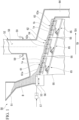
- a stoker type incinerator 50 includes a charging hopper 51 which temporarily stores an incineration material "B", an incinerator 52 which burns the incineration material "B”, a feeder 53 which supplies the incineration material "B” to the incinerator 52, a stoker 54 (including fire grates 1 of a drying stage 61, a combustion stage 62, and a post-combustion stage 63) which is provided on a bottom portion side of the incinerator 52, and a wind box 55 which is provided below the stoker 54.
- the feeder 53 extrudes the incineration material "B", which is continuously supplied onto a feed table 56 via the charging hopper 51, into the incinerator 52.
- the feeder 53 reciprocates on the feed table 56 with a predetermined stroke by a feeder driving device 57.
- the wind box 55 supplies primary air supplied from a blower (not illustrated) to each portion of the stoker 54.
- the incinerator 52 is provided above the stoker 54 and has a combustion chamber 58 including a primary combustion chamber and a secondary combustion chamber.
- the incinerator 52 has a secondary air supply nozzle 59 which supplies secondary air to the combustion chamber 58.
- the stoker 54 is a combustion device in which the grate bars 1 are arranged in a stepwise manner.
- the incineration material "B" burns on the stoker 54.
- a direction in which the incineration material "B” is transported is referred to as a transport direction "TD".
- the incineration material "B” is transported on the stoker 54 in the transport direction "TD".
- a right side is a downstream side TD1 in the transport direction.
- the stoker 54 has a drying stage 61 which dries the incineration material "B", a combustion stage 62 which incinerates the incineration material "B”, and a post-combustion stage 63 which completely incinerates (post-combustion) unburned combustibles, in order from an upstream side in the transport direction of the incineration material B.
- drying, combustion, and post-combustion are performed on the incineration material "B” while the incineration material "B” is sequentially transported in the drying stage 61, the combustion stage 62, and the post-combustion stage 63.
- Each of the stages 61, 62, and 63 has a fixed grate bar stage having a plurality of fixed grate bars 1a and a moving grate bar stage having a plurality of moving grate bars 1b.
- the fixed grate bar stage is configured by disposing the plurality of fixed grate bars 1a in a width direction (a depth direction in Fig. 1 ) of the stoker 54.
- the moving grate bar stage is configured by disposing the plurality of moving grate bars 1b in the width direction of the stoker 54.
- the fixed grate bar 1a (fixed grate bar stage) and the moving grate bar 1b (moving grate bar stage) are alternately disposed in the transport direction "TD".
- the moving grate bar 1b reciprocates in the transport direction "TD" of the incineration material B.
- the incineration material B on the stoker 54 is transported and agitated by the reciprocating motion of the moving grate bar 1b. That is, a lower portion of the incineration material "B" is moved and replaced with an upper portion of the incineration material "B".
- the drying stage 61 receives the incineration material "B" which is extruded by the feeder 53 and dropped into the incinerator 52, and evaporates a moisture of the incineration material “B” and partially thermal-decomposes the incineration material "B".
- the combustion stage 62 ignites the incineration material "B” dried in the drying stage 61 by the primary air supplied from a lower wind box 55, and burns volatiles and fixed carbon components of the incineration material "B".
- the post-combustion stage 63 burns an unburned component such as a fixed carbon component which has passed without being burned in the combustion stage 62 until the unburned combustibles are completely turned into ash.
- the ash is discharged from the incinerator 52 through a slag chute 64 provided at an outlet of the post-combustion stage 63.
- Each of the stages 61, 62, and 63 has a drive mechanism 65 which drives the moving grate bars 1b.
- driving speeds of the moving grate bars 1b in the drying stage 61, the combustion stage 62, and the post-combustion stage 63 can be set to be the same or the driving speeds of at least some moving grate bars 1b in the drying stage 61, the combustion stage 62, and the post-combustion stage 63 can be set to be different from each other.
- shapes of the fixed grate bar 1a and the moving grate bar 1b of the present embodiment will be described.
- the shapes of the fixed grate bar 1a and the moving grate bar 1b are the same. Accordingly, hereinafter, the fixed grate bar 1a and the moving grate bar 1b will be described as the grate bar 1.
- some of the fixed grate bars 1a and the moving grate bars 1b may be grate bars having a projection.
- the grate bar having the projection has a projection protruding upward at a distal end of the grate bar 1, but the other structures are the same as those of the grate bar 1 described below.
- the grate bar 1 of the present embodiment has a cooling structure.
- the grate bar 1 is cooled using the primary air supplied from the wind box 55 as cooling air (cooling medium).
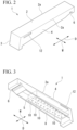
- the grate bar 1 includes an upper wall portion 2 which extends in a first direction “D" (the transport direction "TD" of the refuse), a front wall portion 3 which extends downward from a distal end (an end portion on the downstream side TD1 in the transport direction) of the upper wall portion 2, a pair of side wall portions 4 which extends downward from a side edge 2a of the upper wall portion 2, and a rear wall portion 5.
- An upper surface of the upper wall portion 2 is a surface on which the refuse is placed.
- the upper wall portion 2, the front wall portion 3, the pair of side wall portions 4, and the rear wall portion 5 are formed integrally.
- a concave portion 6 is formed at a rear end of the upper wall portion 2.
- the concave portion 6 of the grate bar 1 is fitted into a convex portion (not illustrated) provided on each of installation surfaces 61a, 62a, and 63a (refer to Fig. 1 ) of the respective stages 61, 62, and 63. Thereby, the grate bars 1 are attached to each of the stages 61, 62, and 63.
- the upper wall portion 2 has a rectangular shape and forms an upper surface of the stoker 54 together with the grate bar 1 adjacent in a width direction "W" (a direction orthogonal to the first direction "D").
- the front wall portion 3 is formed so as to protrude downward from the upper wall portion 2 so that a main surface of the upper wall portion 2 and a main surface of the front wall portion 3 intersect each other at an angle close to a right angle.
- a thickness of the front wall portion 3 is larger than thicknesses of the upper wall portion 2 and the side wall portion 4.
- the side wall portion 4 is formed so that the main surface of the upper wall portion 2 and a main surface of the side wall portion 4 intersect each other at a substantially right angle.
- the side wall portion 4 is formed so that a width thereof increases toward the distal end of the grate bar 1.
- the rear wall portion 5 has a plate shape protruding downward from the upper wall portion 2 and is formed so that a main surface of the rear wall portion 5 faces the first direction "D".
- the rear wall portion 5 is disposed in a rear portion (between the front wall portion 3 and the concave portion 6 and on the concave portion 6 side) of the grate bar 1.
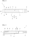
- a channel "S" is formed below the upper wall portion 2 (on a back side of the upper wall portion 2).
- the grate bar 1 includes the upper wall portion 2, the front wall portion 3, the pair of side wall portions 4, and a partition wall 8 that vertically divides the channel "S".
- the partition wall 8 has a plate shape and is attached so as to be parallel to the upper wall portion 2.
- the partition wall 8 has a partition wall main body 9 of which a main surface faces the upper wall portion 2 and which divides the channel "S" into an upper channel S1 between the upper wall portion 2 and the partition wall 8 and a lower channel S2 below the partition wall 8, and a plurality of cooling holes 10 which are formed in the partition wall main body 9.
- the plurality of cooling holes 10 are uniformly disposed in the partition wall main body 9.
- the plurality of cooling holes 10 can be disposed in a lattice shape.
- the number and sizes of the plurality of cooling holes 10 are set so that the grate bar 1 does not float due to a pressure loss of the cooling hole 10, that is, the pressure loss may be set to 500 mmAq (4.90 kPa) or less.
- An air discharge hole 12 through which the cooling air is discharged from the upper channel S1 is formed in the side wall portion 4.
- the air discharge hole 12 is disposed on a distal end side in the first direction "D".
- the cooling air “C” passes through the plurality of cooling holes 10 which are formed in the partition wall 8, and is ejected to a back surface of the upper wall portion 2.
- the cooling air “C” flows so as to collide with the upper wall portion 2, and thereafter, the cooling air “C” is discharged from the air discharge holes 12. Thereby, the upper wall portion 2 is impingement-cooled.
- the cooling air "C” ejected from the cooling holes 10 directly collides with the upper wall portion 2 and the cooling air "C” directly transports heat. Therefore, heat transfer coefficient increases. As a result, cooling performance can be improved. That is, the cooling air "C” collides with the upper wall portion 2, and thus, the cooling performance of the grate bar 1 can be improved.
- a shape of the cooling hole 10 is circular, but the shape is not limited to this.
- the shape of the cooling hole 10 may be elliptical or polygonal.
- the cooling medium used for cooling is the primary air.
- steam may be supplied to the grate bar 1 to perform cooling.
- the air discharge holes 12 are formed in a square shape, but the embodiment is not limited to this.
- the air discharge holes 12 may be circular or elliptical.
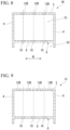
- a plurality of air discharge holes 12B of the grate bar 1 of the present embodiment are formed in the upper wall portion 2.
- Each of the plurality of air discharge holes 12B has a slit shape (a long hole) extending in the first direction "D".
- the plurality of air discharge holes 12B are formed closer to the distal end side than a center portion of the upper wall portion 2 in the first direction "D”.
- the air discharge holes 12B are formed at equal intervals in the width direction "W".
- An area of each air discharge hole 12B is set such that the flow velocity of the cooling air discharged from the air discharge hole 12B is equal to or higher than terminal velocities of dust particles.
- the number of the air discharge holes 12B and position of the air discharge holes 12B in the width direction "W" correspond to those of the cooling holes 10.
- the air discharge holes 12 and the cooling holes 10 overlap each other.
- the number of the air discharge holes 12B and the positions of the air discharge holes 12B in the width direction "W" need not correspond to the cooling holes 10. That is, when viewed from the normal direction of the main surface of the upper wall portion 2, the air discharge holes 12 and the cooling holes 10 may not overlap each other.
- the slit-shaped air discharge holes 12B are provided in the upper wall portion 2 of the grate bar 1B, and thus, the degree of freedom in a size and shape of the air discharge hole 12B can be improved.
- the air discharge holes 12B and the cooling holes 10 do not overlap each other when viewed from the normal direction of the main surface of the upper wall portion 2.
- four air discharge holes 12B are formed in the width direction "W".
- the cooling holes 10 are formed between the air discharge holes 12B adjacent to each other in the width direction "W" when viewed from the normal direction of the main surface of the upper wall portion 2. That is, air ejected from the cooling holes 10 hits the upper wall portion 2 and is then discharged from the air discharge holes 12B.
- the cooling air ejected from the cooling holes 10 reliably hits the upper wall portion 2. Therefore, cooling performance of the impinging jet can be reliably obtained even at locations where the slit-shaped air discharge holes 12B are formed.
- a partition wall main body 9D of the partition wall 8 of the present embodiment includes a main portion 14 which is substantially parallel to the upper wall portion 2 and a distal end portion 15 which is connected to a distal end side of the main portion 14.
- the distal end portion 15 is formed such that a main surface of the distal end portion 15 is substantially parallel to the front wall portion 3.
- the main portion 14 and the distal end portion 15 are smoothly connected to each other. At least some of the plurality of cooling holes 10 formed in the distal end portion 15 are directed so that the cooling air "C" ejected from the cooling holes 10 hits the front wall portion 3.
- the cooling air "C" ejected from the cooling holes 10 hits not only the upper wall portion 2 but also the front wall portion 3 (a distal end of the grate bar 1D). Therefore, cooling performance of the distal end of the grate bar 1D can be improved.
- the distal end portion 15 is formed so as to be substantially parallel to the front wall portion 3.
- the present invention is not limited to this as long as the distal end portion 15 is formed so that the cooling air "C" ejected from the cooling holes 10 hits the front wall portion 3.
- an angle between the main portion 14 and the distal end portion 15 may be obtuse, or the distal end portion 15 may be a plate having a curvature.
- a grate bar 1E of the present embodiment has fins 16 formed on the upper wall portion 2.
- Each of the fins 16 has a plate shape and is provided integrally with the upper wall portion 2 on a back surface 2b of the upper wall portion 2.
- the fin 16 is formed so as to protrude downward from the upper wall portion 2.
- the fin 16 is formed such that the main surface of the fin 16 is along the first direction “D” and faces the width direction "W”.
- the fins 16 are formed on the upper wall portion 2. Accordingly, a heat radiation effect can be obtained. Therefore, cooling performance of the grate bar 1E is improved.
- a cooling hole 10F of a grate bar 1F of the present embodiment has a circular shape.
- An inner peripheral surface 10a of the cooling hole 10F has a conical shape of which a diameter decreases upward (toward the upper wall portion 2).
- the cooling hole 10F is formed such that Di1 > Di2 is satisfied, where Di1 is an inner diameter of a lower end and Di2 is an inner diameter of an upper end.
- the inner diameter Di1 on an inlet side of the cooling hole 10F increases. Therefore, a pressure loss due to the cooling hole 10F can be reduced. Further, the inner diameter Di2 on an outlet side of the cooling hole 10F is reduced. Therefore, a flow velocity of the cooling air can increase and the cooling performance can be improved.
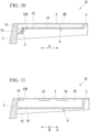
- a grate bar 1G of the present embodiment includes the upper wall portion 2, the front wall portion 3, the pair of side wall portions 4, the rear wall portion 5, and a duct 18 which is fixed to the rear wall portion 5 and extends in the first direction "D".
- the duct 18 is disposed in a space surrounded by the upper wall portion 2 and the pair of side wall portions 4.
- the duct 18 has a rectangular tubular duct main body 19 which extends in the first direction "D", a plurality of cooling holes 10 which are formed in the duct main body 19 and injects the cooling air "C" toward the back surface of the upper wall portion 2, the back surface of the front wall portion 3, the back surfaces of the pair of side wall portions 4 to perform impingement-cooling, and an air introduction hole 11 which is formed on a rear end of the duct main body 19.
- the duct main body 19 has a first surface 21 which is parallel to the upper wall portion 2, a pair of second surfaces 22 which is parallel to the side wall portions 4, a third surface 23 which is parallel to the first surface 21 and forms a rectangular tube together with the first surface 21 and the pair of second surfaces 22, and a fourth surface 24 which closes a distal end of the duct main body 19.
- the cooling holes 10 are regularly formed in the first surface 21 and the pair of second surfaces 22.
- An axis A of each cooling hole 10 formed in the second surface 22 is not orthogonal to the second surface 22 and is inclined.
- the cooling hole 10 formed in the second surface 22 is inclined so that an outer side of the cooling hole 10 is higher. Accordingly, the cooling air "C" ejected from the cooling hole 10 is ejected upward.
- the cooling air ejected from the cooling holes 10 of the duct 18 hits the upper wall portion 2, the side wall portions 4, and the front wall portion 3 so as to cool the wall portions. Thereafter, the cooling air is discharged from the gap "G" between the side wall portions 4 and the duct 18 on a bottom side of the grate bar 1.
- the gap "G" between the side wall portions 4 and the duct 18 functions as an air discharge hole that is long in the first direction "D", and thus, the cross flow is eliminated. Therefore, effects of the impinging jet can be maximized.
- the structure of the grate bar 1G can be simplified.
- the structure of the grate bar 1G is simplified, and thus, a maintenance of the grate bar 1G is facilitated.
- a shape of the duct main body 19 is a rectangular tube.
- the shape of the duct main body 19 is not limited to this as long as the duct main body 19 is tubular.
- the shape of the duct main body 19 may be cylindrical.
- the cooling medium ejected from the cooling holes directly collides with the upper wall portion and the front wall portion, so that the cooling performance can be improved.
Landscapes
- Engineering & Computer Science (AREA)
- Chemical & Material Sciences (AREA)
- Combustion & Propulsion (AREA)
- Mechanical Engineering (AREA)
- General Engineering & Computer Science (AREA)
- Incineration Of Waste (AREA)
- Curing Cements, Concrete, And Artificial Stone (AREA)
- Coke Industry (AREA)
- Turbine Rotor Nozzle Sealing (AREA)
Claims (5)
- Roststab (1, 1B, 1C, 1D, 1E, 1F, 1G), umfassend:einen oberen Wandabschnitt (2), der sich in eine erste Richtung (D) erstreckt,einen vorderen Wandabschnitt (3), der sich von einem distalen Ende des oberen Wandabschnitts (2) nach unten erstreckt;einen Kanal (S), der auf einer hinteren Seite des oberen Wandabschnitts (2) gebildet ist;und eine Teilungswand (8), die den Kanal (S) vertikal unterteilt und einen Teilungswandhauptkörper (9D) beinhaltet, von dem eine Hauptoberfläche dem oberen Wandabschnitt (2) gegenüberliegt, und eine Vielzahl von Kühlungslöchern (10), die im Teilungswandhauptkörper (9D) gebildet sind, und die konfiguriert sind, um ein Kühlmedium (C) hin zu einer hinteren Oberfläche des oberen Wandabschnitts (2) auszustoßen, um den oberen Wandabschnitt (2) durch Aufprallkühlung zu kühlen,dadurch gekennzeichnet, dass der Roststab ein Paar Seitenwandabschnitte (4) umfasst, die sich von einer Seitenkante (2a) des oberen Wandabschnitts (2) nach unten erstrecken; undeinen hinteren Wandabschnitt (5), der eine Plattenform aufweist, die vom oberen Wandabschnitt (2) nach unten vorspringt und derart geformt ist, dass die Hauptoberfläche des hinteren Wandabschnitts (5) der ersten Richtung (D) gegenüberliegt, wobei der obere Wandabschnitt (2), der vordere Wandabschnitt (3), das Paar Seitenwandabschnitte (4) und der hintere Wandabschnitt (5) einstückig gebildet sind,wobei der Teilungswandhauptkörper (9D) mit dem vorderen Wandabschnitt (3), dem Paar Seitenwandabschnitten (4) und dem hinteren Wandabschnitt (5) verbunden ist,wobei der Teilungswandhauptkörper (9D) den Kanal (S) in einen oberen Kanal (S1) zwischen dem oberen Wandabschnitt (2) und dem Teilungswandhauptkörper (9D) und einen unteren Kanal (S2) unter dem Teilungswandhauptkörper (9D) unterteilt,wobei der Teilungswandhauptkörper (9D) Folgendes beinhaltet;einen Hauptabschnitt (14), der parallel zum oberen Wandabschnitt (2) ist, undeinen distalen Abschnitt (15), der mit einer distalen Endseite des Hauptabschnitts (14) verbunden ist, undwobei mindestens eines der Vielzahl von Kühlungslöchern (10), die im distalen Ende (15) gebildet sind, derart ausgerichtet ist, dass das Kühlmedium (C), das von mindestens einem der Vielzahl von Kühlungslöchern (10) ausgestoßen wird, konfiguriert ist, um auf den vorderen Wandabschnitt (3) im oberen Kanal (S1) zu treffen.
- Roststab (1, 1B, 1C, 1D, 1E, 1F, 1G) nach Anspruch 1,
wobei, wenn eine Distanz zwischen der Teilungswand (8) und dem oberen Wandabschnitt (2) "L" ist und ein Innendurchmesser der Vielzahl von Kühlungslöchern (10), "Di" ist, 2 < "L/Di" < 35 erfüllt ist. - Roststab (1, 1B, 1C, 1D, 1E, 1F, 1G) nach Anspruch 1 oder 2, weiter umfassend:einen Schlitz (12B), der geformt ist, um sich in der ersten Richtung (D) auf der distalen Endseite von einem zentralen Abschnitt des oberen Wandabschnitts (2) in der ersten Richtung (D) zu erstrecken, und durch den das Kühlmedium (C) im Kanal (S) zwischen der Teilungswand (8) und dem oberen Wandabschnitt (2) entladen wird,wobei der Schlitz (12B) und die Vielzahl von Kühlungslöchern (10) derart geformt sind, dass der Schlitz (12B) und die Vielzahl von Kühlungslöchern (10) einander nicht überlappen, wenn aus einer normalen Richtung der Hauptoberfläche des oberen Wandabschnitts (2) betrachtet.
- Roststab (1, 1B, 1C, 1D, 1E, 1F, 1G) nach einem der Ansprüche 1 bis 3, weiter umfassend:
eine plattenförmige Rippe (16), die einstückig mit dem oberen Wandabschnitt (2) auf der hinteren Oberfläche des oberen Wandabschnitts (2) bereitgestellt und geformt ist, um vom oberen Wandabschnitt (2) nach unten vorzuspringen (2). - Roststab (1, 1B, 1C, 1D, 1E, 1F, 1G) nach einem der Ansprüche 1 bis 3,
wobei die Vielzahl von Kühlungslöchern (10F) eine runde Form aufweisen und innere Umfangsoberflächen (10a) der Vielzahl von Kühlungslöchern (10F) eine konische Form aufweisen, deren Durchmesser nach oben abnimmt.
Applications Claiming Priority (2)
| Application Number | Priority Date | Filing Date | Title |
|---|---|---|---|
| JP2018004543U JP3219985U (ja) | 2018-11-22 | 2018-11-22 | 火格子 |
| PCT/JP2019/026978 WO2020105217A1 (ja) | 2018-11-22 | 2019-07-08 | 火格子 |
Publications (3)
| Publication Number | Publication Date |
|---|---|
| EP3885652A1 EP3885652A1 (de) | 2021-09-29 |
| EP3885652A4 EP3885652A4 (de) | 2022-08-31 |
| EP3885652B1 true EP3885652B1 (de) | 2024-08-07 |
Family
ID=65228737
Family Applications (1)
| Application Number | Title | Priority Date | Filing Date |
|---|---|---|---|
| EP19886731.9A Active EP3885652B1 (de) | 2018-11-22 | 2019-07-08 | Feuerungsrost |
Country Status (11)
| Country | Link |
|---|---|
| EP (1) | EP3885652B1 (de) |
| JP (1) | JP3219985U (de) |
| KR (2) | KR200497218Y1 (de) |
| CN (1) | CN212869812U (de) |
| DK (1) | DK3885652T3 (de) |
| MY (1) | MY205756A (de) |
| PH (1) | PH22020550010U3 (de) |
| PL (1) | PL3885652T3 (de) |
| RU (1) | RU206500U1 (de) |
| SG (1) | SG11202006518QA (de) |
| WO (1) | WO2020105217A1 (de) |
Families Citing this family (2)
| Publication number | Priority date | Publication date | Assignee | Title |
|---|---|---|---|---|
| CN115103980A (zh) * | 2020-12-04 | 2022-09-23 | 施天翔 | 炉条以及炉条装置 |
| AT526670B1 (de) * | 2023-03-27 | 2024-06-15 | Polytechnik Luft Und Feuerungstechnik Gmbh | Treppenrost für Festbrennstoff-Gegenstromvergaser |
Family Cites Families (11)
| Publication number | Priority date | Publication date | Assignee | Title |
|---|---|---|---|---|
| US2257287A (en) * | 1939-06-01 | 1941-09-30 | Comb Eng Co Inc | Grate bar |
| DE2806974C2 (de) * | 1978-02-18 | 1980-01-31 | Josef Martin Feuerungsbau Gmbh, 8000 Muenchen | Roststab für Rostbeläge, insbesondere von Feuerungen |
| JPS6086730U (ja) * | 1983-11-14 | 1985-06-14 | 三菱重工業株式会社 | 耐熱火格子 |
| DE3734043A1 (de) * | 1987-10-08 | 1989-04-20 | Kloeckner Humboldt Deutz Ag | Rostkuehler zum kuehlen von heissem schuettgut |
| JPH06265125A (ja) | 1993-03-15 | 1994-09-20 | Unitika Ltd | ごみ焼却炉の火格子 |
| CH684118A5 (de) * | 1993-04-20 | 1994-07-15 | Doikos Investments Ltd | Verfahren zum Verbrennen von Kehricht auf einem Verbrennungsrost sowie Verbrennungsrost zur Ausübung des Verfahrens und Rostplatte für einen solchen Verbrennungsrost. |
| EP0924464A1 (de) * | 1997-12-19 | 1999-06-23 | KOCH, Theodor | Verfahren zur Kühlung des Rostes von Verbrennungsanlagen und Verbrennungsrost |
| JP3919094B2 (ja) | 2002-07-04 | 2007-05-23 | 株式会社タクマ | 階段式ストーカ |
| CN2654607Y (zh) * | 2003-10-15 | 2004-11-10 | 燕山大学 | 冷却高温散料用的变流阻箅板 |
| JP5111033B2 (ja) * | 2007-09-26 | 2012-12-26 | 日立造船株式会社 | 廃棄物焼却炉の火格子ブロック |
| JP6046852B1 (ja) | 2016-07-06 | 2016-12-21 | 株式会社エクサ | 形状解析プログラム |
-
2018
- 2018-11-22 JP JP2018004543U patent/JP3219985U/ja active Active
-
2019
- 2019-07-08 DK DK19886731.9T patent/DK3885652T3/da active
- 2019-07-08 SG SG11202006518QA patent/SG11202006518QA/en unknown
- 2019-07-08 PL PL19886731.9T patent/PL3885652T3/pl unknown
- 2019-07-08 EP EP19886731.9A patent/EP3885652B1/de active Active
- 2019-07-08 MY MYPI2020003610A patent/MY205756A/en unknown
- 2019-07-08 WO PCT/JP2019/026978 patent/WO2020105217A1/ja not_active Ceased
- 2019-07-08 PH PH2/2020/550010U patent/PH22020550010U3/en unknown
- 2019-07-08 KR KR2020217000043U patent/KR200497218Y1/ko active Active
- 2019-07-08 KR KR1020217014151A patent/KR20210076060A/ko not_active Withdrawn
- 2019-07-08 RU RU2020122866U patent/RU206500U1/ru active
- 2019-07-08 CN CN201990000396.6U patent/CN212869812U/zh active Active
Also Published As
| Publication number | Publication date |
|---|---|
| CN212869812U (zh) | 2021-04-02 |
| PH22020550010U1 (en) | 2022-06-03 |
| MY205756A (en) | 2024-11-11 |
| KR20210076060A (ko) | 2021-06-23 |
| JP3219985U (ja) | 2019-01-31 |
| KR20210001749U (ko) | 2021-07-28 |
| BR112020014213A2 (pt) | 2021-07-27 |
| DK3885652T3 (da) | 2024-09-23 |
| EP3885652A4 (de) | 2022-08-31 |
| WO2020105217A1 (ja) | 2020-05-28 |
| PH22020550010U3 (en) | 2023-06-14 |
| KR200497218Y1 (ko) | 2023-08-31 |
| SG11202006518QA (en) | 2020-08-28 |
| PL3885652T3 (pl) | 2024-12-23 |
| EP3885652A1 (de) | 2021-09-29 |
| RU206500U1 (ru) | 2021-09-14 |
Similar Documents
| Publication | Publication Date | Title |
|---|---|---|
| JP7254445B2 (ja) | ごみ焼却炉の火格子の冷却構造、ごみ焼却炉の火格子の冷却方法及びごみ焼却炉の燃焼用空気予熱方法 | |
| EP3885652B1 (de) | Feuerungsrost | |
| JP5336876B2 (ja) | バイオ燃料の燃焼装置 | |
| US6964237B2 (en) | Grate block for a refuse incineration grate | |
| CN86105250A (zh) | 冲击冷却过渡进气道 | |
| US5488943A (en) | Self-distributing combustion grate for pellet fueled stoves | |
| JP5160616B2 (ja) | タービン用バーナ及びそのバーナを備えるガスタービン | |
| JP7416822B2 (ja) | ストーカ炉 | |
| JP2008190808A (ja) | 燃焼装置 | |
| JP7474743B2 (ja) | 焼却炉 | |
| BR112020014213B1 (pt) | Barra de grelha | |
| EP2458274B1 (de) | Feststoffpartikel-Brenner mit spezieller Oberluft-Einspritzung | |
| KR20130103806A (ko) | 고체 연료 버너 | |
| CN215062010U (zh) | 一种复合燃烧炉床及对应的锅炉 | |
| JPH1061495A (ja) | 航空機エンジンのフレームホルダ | |
| US20060000396A1 (en) | Grate panel, as well as corresponding incineration grate and waste incineration plant | |
| JP2001108221A (ja) | 焼却炉 | |
| JP7357100B1 (ja) | 火格子および火格子の運転方法 | |
| JP6109400B1 (ja) | 耐火物及び焼却炉 | |
| JPH11201443A (ja) | Rdf燃焼煙管ボイラ | |
| JP6800251B2 (ja) | 流動床式焼却炉 | |
| JPH074635A (ja) | ストーカ式焼却炉のロストル構造 | |
| JP4257290B2 (ja) | 熱風乾燥機 | |
| JP6814727B2 (ja) | ボイラ | |
| JP2540669Y2 (ja) | ストーカ式燃焼炉の乾燥ストーカ装置 |
Legal Events
| Date | Code | Title | Description |
|---|---|---|---|
| STAA | Information on the status of an ep patent application or granted ep patent |
Free format text: STATUS: THE INTERNATIONAL PUBLICATION HAS BEEN MADE |
|
| PUAI | Public reference made under article 153(3) epc to a published international application that has entered the european phase |
Free format text: ORIGINAL CODE: 0009012 |
|
| STAA | Information on the status of an ep patent application or granted ep patent |
Free format text: STATUS: REQUEST FOR EXAMINATION WAS MADE |
|
| 17P | Request for examination filed |
Effective date: 20200710 |
|
| AK | Designated contracting states |
Kind code of ref document: A1 Designated state(s): AL AT BE BG CH CY CZ DE DK EE ES FI FR GB GR HR HU IE IS IT LI LT LU LV MC MK MT NL NO PL PT RO RS SE SI SK SM TR |
|
| DAV | Request for validation of the european patent (deleted) | ||
| DAX | Request for extension of the european patent (deleted) | ||
| REG | Reference to a national code |
Ref country code: DE Ref legal event code: R079 Free format text: PREVIOUS MAIN CLASS: F23H0003020000 Ipc: F23H0001020000 Ref country code: DE Ref legal event code: R079 Ref document number: 602019056777 Country of ref document: DE Free format text: PREVIOUS MAIN CLASS: F23H0003020000 Ipc: F23H0001020000 |
|
| A4 | Supplementary search report drawn up and despatched |
Effective date: 20220729 |
|
| RIC1 | Information provided on ipc code assigned before grant |
Ipc: F23H 17/12 20060101ALI20220725BHEP Ipc: F23H 7/08 20060101ALI20220725BHEP Ipc: F23H 11/18 20060101ALI20220725BHEP Ipc: F23H 3/02 20060101ALI20220725BHEP Ipc: F23H 1/02 20060101AFI20220725BHEP |
|
| STAA | Information on the status of an ep patent application or granted ep patent |
Free format text: STATUS: EXAMINATION IS IN PROGRESS |
|
| 17Q | First examination report despatched |
Effective date: 20230720 |
|
| GRAP | Despatch of communication of intention to grant a patent |
Free format text: ORIGINAL CODE: EPIDOSNIGR1 |
|
| STAA | Information on the status of an ep patent application or granted ep patent |
Free format text: STATUS: GRANT OF PATENT IS INTENDED |
|
| INTG | Intention to grant announced |
Effective date: 20240320 |
|
| GRAS | Grant fee paid |
Free format text: ORIGINAL CODE: EPIDOSNIGR3 |
|
| P01 | Opt-out of the competence of the unified patent court (upc) registered |
Effective date: 20240530 |
|
| GRAA | (expected) grant |
Free format text: ORIGINAL CODE: 0009210 |
|
| STAA | Information on the status of an ep patent application or granted ep patent |
Free format text: STATUS: THE PATENT HAS BEEN GRANTED |
|
| AK | Designated contracting states |
Kind code of ref document: B1 Designated state(s): AL AT BE BG CH CY CZ DE DK EE ES FI FR GB GR HR HU IE IS IT LI LT LU LV MC MK MT NL NO PL PT RO RS SE SI SK SM TR |
|
| REG | Reference to a national code |
Ref country code: GB Ref legal event code: FG4D |
|
| REG | Reference to a national code |
Ref country code: CH Ref legal event code: EP |
|
| REG | Reference to a national code |
Ref country code: DE Ref legal event code: R096 Ref document number: 602019056777 Country of ref document: DE |
|
| REG | Reference to a national code |
Ref country code: IE Ref legal event code: FG4D |
|
| REG | Reference to a national code |
Ref country code: DK Ref legal event code: T3 Effective date: 20240919 |
|
| REG | Reference to a national code |
Ref country code: NL Ref legal event code: FP |
|
| REG | Reference to a national code |
Ref country code: LT Ref legal event code: MG9D |
|
| REG | Reference to a national code |
Ref country code: AT Ref legal event code: MK05 Ref document number: 1711319 Country of ref document: AT Kind code of ref document: T Effective date: 20240807 |
|
| PG25 | Lapsed in a contracting state [announced via postgrant information from national office to epo] |
Ref country code: FI Free format text: LAPSE BECAUSE OF FAILURE TO SUBMIT A TRANSLATION OF THE DESCRIPTION OR TO PAY THE FEE WITHIN THE PRESCRIBED TIME-LIMIT Effective date: 20240807 Ref country code: PT Free format text: LAPSE BECAUSE OF FAILURE TO SUBMIT A TRANSLATION OF THE DESCRIPTION OR TO PAY THE FEE WITHIN THE PRESCRIBED TIME-LIMIT Effective date: 20241209 Ref country code: GR Free format text: LAPSE BECAUSE OF FAILURE TO SUBMIT A TRANSLATION OF THE DESCRIPTION OR TO PAY THE FEE WITHIN THE PRESCRIBED TIME-LIMIT Effective date: 20241108 |
|
| PG25 | Lapsed in a contracting state [announced via postgrant information from national office to epo] |
Ref country code: BG Free format text: LAPSE BECAUSE OF FAILURE TO SUBMIT A TRANSLATION OF THE DESCRIPTION OR TO PAY THE FEE WITHIN THE PRESCRIBED TIME-LIMIT Effective date: 20240807 |
|
| PG25 | Lapsed in a contracting state [announced via postgrant information from national office to epo] |
Ref country code: LV Free format text: LAPSE BECAUSE OF FAILURE TO SUBMIT A TRANSLATION OF THE DESCRIPTION OR TO PAY THE FEE WITHIN THE PRESCRIBED TIME-LIMIT Effective date: 20240807 |
|
| PG25 | Lapsed in a contracting state [announced via postgrant information from national office to epo] |
Ref country code: AT Free format text: LAPSE BECAUSE OF FAILURE TO SUBMIT A TRANSLATION OF THE DESCRIPTION OR TO PAY THE FEE WITHIN THE PRESCRIBED TIME-LIMIT Effective date: 20240807 Ref country code: IS Free format text: LAPSE BECAUSE OF FAILURE TO SUBMIT A TRANSLATION OF THE DESCRIPTION OR TO PAY THE FEE WITHIN THE PRESCRIBED TIME-LIMIT Effective date: 20241207 |
|
| PG25 | Lapsed in a contracting state [announced via postgrant information from national office to epo] |
Ref country code: HR Free format text: LAPSE BECAUSE OF FAILURE TO SUBMIT A TRANSLATION OF THE DESCRIPTION OR TO PAY THE FEE WITHIN THE PRESCRIBED TIME-LIMIT Effective date: 20240807 |
|
| PG25 | Lapsed in a contracting state [announced via postgrant information from national office to epo] |
Ref country code: RS Free format text: LAPSE BECAUSE OF FAILURE TO SUBMIT A TRANSLATION OF THE DESCRIPTION OR TO PAY THE FEE WITHIN THE PRESCRIBED TIME-LIMIT Effective date: 20241107 Ref country code: ES Free format text: LAPSE BECAUSE OF FAILURE TO SUBMIT A TRANSLATION OF THE DESCRIPTION OR TO PAY THE FEE WITHIN THE PRESCRIBED TIME-LIMIT Effective date: 20240807 |
|
| PG25 | Lapsed in a contracting state [announced via postgrant information from national office to epo] |
Ref country code: RS Free format text: LAPSE BECAUSE OF FAILURE TO SUBMIT A TRANSLATION OF THE DESCRIPTION OR TO PAY THE FEE WITHIN THE PRESCRIBED TIME-LIMIT Effective date: 20241107 Ref country code: PT Free format text: LAPSE BECAUSE OF FAILURE TO SUBMIT A TRANSLATION OF THE DESCRIPTION OR TO PAY THE FEE WITHIN THE PRESCRIBED TIME-LIMIT Effective date: 20241209 Ref country code: LV Free format text: LAPSE BECAUSE OF FAILURE TO SUBMIT A TRANSLATION OF THE DESCRIPTION OR TO PAY THE FEE WITHIN THE PRESCRIBED TIME-LIMIT Effective date: 20240807 Ref country code: IS Free format text: LAPSE BECAUSE OF FAILURE TO SUBMIT A TRANSLATION OF THE DESCRIPTION OR TO PAY THE FEE WITHIN THE PRESCRIBED TIME-LIMIT Effective date: 20241207 Ref country code: HR Free format text: LAPSE BECAUSE OF FAILURE TO SUBMIT A TRANSLATION OF THE DESCRIPTION OR TO PAY THE FEE WITHIN THE PRESCRIBED TIME-LIMIT Effective date: 20240807 Ref country code: GR Free format text: LAPSE BECAUSE OF FAILURE TO SUBMIT A TRANSLATION OF THE DESCRIPTION OR TO PAY THE FEE WITHIN THE PRESCRIBED TIME-LIMIT Effective date: 20241108 Ref country code: FI Free format text: LAPSE BECAUSE OF FAILURE TO SUBMIT A TRANSLATION OF THE DESCRIPTION OR TO PAY THE FEE WITHIN THE PRESCRIBED TIME-LIMIT Effective date: 20240807 Ref country code: ES Free format text: LAPSE BECAUSE OF FAILURE TO SUBMIT A TRANSLATION OF THE DESCRIPTION OR TO PAY THE FEE WITHIN THE PRESCRIBED TIME-LIMIT Effective date: 20240807 Ref country code: BG Free format text: LAPSE BECAUSE OF FAILURE TO SUBMIT A TRANSLATION OF THE DESCRIPTION OR TO PAY THE FEE WITHIN THE PRESCRIBED TIME-LIMIT Effective date: 20240807 Ref country code: AT Free format text: LAPSE BECAUSE OF FAILURE TO SUBMIT A TRANSLATION OF THE DESCRIPTION OR TO PAY THE FEE WITHIN THE PRESCRIBED TIME-LIMIT Effective date: 20240807 |
|
| PG25 | Lapsed in a contracting state [announced via postgrant information from national office to epo] |
Ref country code: SM Free format text: LAPSE BECAUSE OF FAILURE TO SUBMIT A TRANSLATION OF THE DESCRIPTION OR TO PAY THE FEE WITHIN THE PRESCRIBED TIME-LIMIT Effective date: 20240807 Ref country code: RO Free format text: LAPSE BECAUSE OF FAILURE TO SUBMIT A TRANSLATION OF THE DESCRIPTION OR TO PAY THE FEE WITHIN THE PRESCRIBED TIME-LIMIT Effective date: 20240807 |
|
| PG25 | Lapsed in a contracting state [announced via postgrant information from national office to epo] |
Ref country code: EE Free format text: LAPSE BECAUSE OF FAILURE TO SUBMIT A TRANSLATION OF THE DESCRIPTION OR TO PAY THE FEE WITHIN THE PRESCRIBED TIME-LIMIT Effective date: 20240807 |
|
| PG25 | Lapsed in a contracting state [announced via postgrant information from national office to epo] |
Ref country code: CZ Free format text: LAPSE BECAUSE OF FAILURE TO SUBMIT A TRANSLATION OF THE DESCRIPTION OR TO PAY THE FEE WITHIN THE PRESCRIBED TIME-LIMIT Effective date: 20240807 |
|
| PG25 | Lapsed in a contracting state [announced via postgrant information from national office to epo] |
Ref country code: SK Free format text: LAPSE BECAUSE OF FAILURE TO SUBMIT A TRANSLATION OF THE DESCRIPTION OR TO PAY THE FEE WITHIN THE PRESCRIBED TIME-LIMIT Effective date: 20240807 |
|
| REG | Reference to a national code |
Ref country code: DE Ref legal event code: R097 Ref document number: 602019056777 Country of ref document: DE |
|
| PLBE | No opposition filed within time limit |
Free format text: ORIGINAL CODE: 0009261 |
|
| STAA | Information on the status of an ep patent application or granted ep patent |
Free format text: STATUS: NO OPPOSITION FILED WITHIN TIME LIMIT |
|
| PGFP | Annual fee paid to national office [announced via postgrant information from national office to epo] |
Ref country code: PL Payment date: 20250602 Year of fee payment: 7 |
|
| PGFP | Annual fee paid to national office [announced via postgrant information from national office to epo] |
Ref country code: GB Payment date: 20250529 Year of fee payment: 7 |
|
| PGFP | Annual fee paid to national office [announced via postgrant information from national office to epo] |
Ref country code: NL Payment date: 20250613 Year of fee payment: 7 Ref country code: BE Payment date: 20250619 Year of fee payment: 7 |
|
| 26N | No opposition filed |
Effective date: 20250508 |
|
| PGFP | Annual fee paid to national office [announced via postgrant information from national office to epo] |
Ref country code: FR Payment date: 20250610 Year of fee payment: 7 |
|
| PG25 | Lapsed in a contracting state [announced via postgrant information from national office to epo] |
Ref country code: SE Free format text: LAPSE BECAUSE OF FAILURE TO SUBMIT A TRANSLATION OF THE DESCRIPTION OR TO PAY THE FEE WITHIN THE PRESCRIBED TIME-LIMIT Effective date: 20240807 |
|
| PGFP | Annual fee paid to national office [announced via postgrant information from national office to epo] |
Ref country code: DK Payment date: 20250714 Year of fee payment: 7 Ref country code: DE Payment date: 20250528 Year of fee payment: 7 |
|
| PGFP | Annual fee paid to national office [announced via postgrant information from national office to epo] |
Ref country code: NO Payment date: 20250709 Year of fee payment: 7 |
|
| PGFP | Annual fee paid to national office [announced via postgrant information from national office to epo] |
Ref country code: TR Payment date: 20250702 Year of fee payment: 7 |
|
| PGFP | Annual fee paid to national office [announced via postgrant information from national office to epo] |
Ref country code: CH Payment date: 20250801 Year of fee payment: 7 |