EP3882483B1 - Spannungswellengetriebe vom einheitentyp - Google Patents
Spannungswellengetriebe vom einheitentyp Download PDFInfo
- Publication number
- EP3882483B1 EP3882483B1 EP18940134.2A EP18940134A EP3882483B1 EP 3882483 B1 EP3882483 B1 EP 3882483B1 EP 18940134 A EP18940134 A EP 18940134A EP 3882483 B1 EP3882483 B1 EP 3882483B1
- Authority
- EP
- European Patent Office
- Prior art keywords
- toothed gear
- bearing
- externally toothed
- gap portion
- cylindrical barrel
- Prior art date
- Legal status (The legal status is an assumption and is not a legal conclusion. Google has not performed a legal analysis and makes no representation as to the accuracy of the status listed.)
- Active
Links
Images

Classifications
-
- F—MECHANICAL ENGINEERING; LIGHTING; HEATING; WEAPONS; BLASTING
- F16—ENGINEERING ELEMENTS AND UNITS; GENERAL MEASURES FOR PRODUCING AND MAINTAINING EFFECTIVE FUNCTIONING OF MACHINES OR INSTALLATIONS; THERMAL INSULATION IN GENERAL
- F16H—GEARING
- F16H1/00—Toothed gearings for conveying rotary motion
- F16H1/28—Toothed gearings for conveying rotary motion with gears having orbital motion
- F16H1/32—Toothed gearings for conveying rotary motion with gears having orbital motion in which the central axis of the gearing lies inside the periphery of an orbital gear
-
- F—MECHANICAL ENGINEERING; LIGHTING; HEATING; WEAPONS; BLASTING
- F16—ENGINEERING ELEMENTS AND UNITS; GENERAL MEASURES FOR PRODUCING AND MAINTAINING EFFECTIVE FUNCTIONING OF MACHINES OR INSTALLATIONS; THERMAL INSULATION IN GENERAL
- F16H—GEARING
- F16H49/00—Other gearings
- F16H49/001—Wave gearings, e.g. harmonic drive transmissions
-
- F—MECHANICAL ENGINEERING; LIGHTING; HEATING; WEAPONS; BLASTING
- F16—ENGINEERING ELEMENTS AND UNITS; GENERAL MEASURES FOR PRODUCING AND MAINTAINING EFFECTIVE FUNCTIONING OF MACHINES OR INSTALLATIONS; THERMAL INSULATION IN GENERAL
- F16H—GEARING
- F16H57/00—General details of gearing
- F16H57/04—Features relating to lubrication or cooling or heating
- F16H57/0463—Grease lubrication; Drop-feed lubrication
- F16H57/0464—Grease lubrication
-
- F—MECHANICAL ENGINEERING; LIGHTING; HEATING; WEAPONS; BLASTING
- F16—ENGINEERING ELEMENTS AND UNITS; GENERAL MEASURES FOR PRODUCING AND MAINTAINING EFFECTIVE FUNCTIONING OF MACHINES OR INSTALLATIONS; THERMAL INSULATION IN GENERAL
- F16H—GEARING
- F16H57/00—General details of gearing
- F16H57/04—Features relating to lubrication or cooling or heating
- F16H57/0467—Elements of gearings to be lubricated, cooled or heated
- F16H57/0469—Bearings or seals
- F16H57/0471—Bearing
-
- F—MECHANICAL ENGINEERING; LIGHTING; HEATING; WEAPONS; BLASTING
- F16—ENGINEERING ELEMENTS AND UNITS; GENERAL MEASURES FOR PRODUCING AND MAINTAINING EFFECTIVE FUNCTIONING OF MACHINES OR INSTALLATIONS; THERMAL INSULATION IN GENERAL
- F16H—GEARING
- F16H57/00—General details of gearing
- F16H57/04—Features relating to lubrication or cooling or heating
- F16H57/048—Type of gearings to be lubricated, cooled or heated
- F16H57/0482—Gearings with gears having orbital motion
-
- F—MECHANICAL ENGINEERING; LIGHTING; HEATING; WEAPONS; BLASTING
- F16—ENGINEERING ELEMENTS AND UNITS; GENERAL MEASURES FOR PRODUCING AND MAINTAINING EFFECTIVE FUNCTIONING OF MACHINES OR INSTALLATIONS; THERMAL INSULATION IN GENERAL
- F16H—GEARING
- F16H49/00—Other gearings
- F16H49/001—Wave gearings, e.g. harmonic drive transmissions
- F16H2049/003—Features of the flexsplines therefor
Definitions
- the present invention relates to a unit-type strain wave gearing device in which a bearing is provided to support a rigid internally toothed gear and a flexible externally toothed gear in a relative rotatable state, and particularly relates to a unit-type strain wave gearing device in which a meshing section between the internally toothed gear and the externally toothed gear is lubricated by grease.
- a cross roller bearing is arranged in a state of surrounding a circular cylindrical barrel part of a top-hat-shaped externally toothed gear.
- the cross roller bearing has an outer ring, which is fastened to the annular boss formed in the outer peripheral edge of a diaphragm of an externally toothed gear, and an inner ring which is fixed to an internally toothed gear.
- a certain gap is formed between the inner ring of the cross roller bearing and the diaphragm and cylindrical barrel part of the externally toothed gear so that both members do not interfere with each other.
- the gap is communicated with a meshing section between the internally toothed gear and the externally toothed gear and is also communicated with a raceway groove between the inner and outer rings of the cross roller bearing.
- a cross roller bearing is arranged in a state of surrounding the circular cylindrical barrel part of a cup-shaped externally toothed gear. There is formed a prescribed gap between the inner ring of the cross roller bearing and the diaphragm and cylindrical barrel part of the externally toothed gear. The gap is communicated with a meshing section between the internally toothed gear and the externally toothed gear and is communicated with the raceway groove of the cross roller bearing.
- Patent document 3 it has been proposed that an oil supply hole is formed in an externally toothed gear in order to allow lubricant oil provided from the outside of the strain wave gearing device to flow into the inside of the strain wave gearing device.
- a wave reduction gear is disposed inside a device case of a rotating table device.
- Lubrication oil is sprayed from an oil supply channel, which is formed in the device case, toward an oil supply hole formed in a cup-shaped flexible externally toothed gear.
- a wave bearing disposed in the interior is lubricated via the oil supply hole.
- Lubricating oil that has entered into the flexible externally toothed gear is forcibly suctioned to the exterior via an oil recovery channel that is formed in the device case.
- a meshing section between two gears is sometimes lubricated by grease which is coated on or filled in the meshing section beforehand.
- the cylindrical barrel part of the externally toothed gear, in which external teeth are formed is repeatedly flexed in a radial direction by a wave generator. Due to the pump effect caused by deflection of the external gear in the radial direction, grease is pushed from the meshing section which is lubricated by the grease. Grease pushed out therefrom flows into a gap formed between the cylindrical barrel part of the externally toothed gear and the inner ring of a cross roller bearing.
- the grease which was flowed into the gap, passes through the gap and flows into the raceway groove formed between the inner and outer rings of the cross roller bearing.
- the grease may be leaked out to the outside through the oil seal.
- an object of the present invention is to provide a unit-type strain wave gearing device which is able to prevent or suppress leakage of grease to the outside of the unit through an oil seal of a bearing for supporting an internally toothed gear and an externally toothed gear in a relatively rotatable state.
- a unit-type strain wave gearing device including an externally toothed gear having a top-hat shape according to independent claim 1
- a unit-type strain wave gearing device including an externally toothed gear having a cup shape according to independent claim 2.
- Grease which is coated on or filled in the meshing section of the two gears is forced to push out toward the diaphragm due to the pump effect caused by repeating radial deflection of the cylindrical barrel part of the externally toothed gear by the wave generator.
- the pushed-out grease flows into the gap between the cylindrical barrel part of the externally toothed gear and the bearing.
- This gap communicates with the raceway groove of the bearing and also with the inner space of the externally toothed gear via the grease-flowing hole formed in the externally toothed gear. Accordingly, part of the grease pushed out from the meshing section flows into the inner space of the externally toothed gear via the grease-flowing hole, whereby reducing the amount of grease flowing into the raceway groove via the gap. Since the amount of grease, which reaches the raceway groove, can therefore be reduced, it is possible to prevent or suppress leakage of grease from the raceway groove to the outside of the device through the oil seal.
- the grease-flowing hole may be formed in the diaphragm, for example, at equiangular intervals or different angular intervals in the circumferential direction thereof.
- the grease-flowing hole can be a through hole of circular, oval, polygonal or other shape.
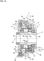
- FIG. 1A is a schematic longitudinal cross-sectional view showing a unit-type strain wave gearing device according to Embodiment 1 of the present invention
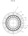
- FIG. 1B is a schematic lateral cross-sectional view showing a portion of the unit-type strain wave gearing device cut along line 1B-1B of FIG. 1A
- FIG. 1C is a perspective view showing an internally toothed gear and an externally toothed gear.
- a unit-type strain wave gearing device 1 (hereinafter simply refers to as a "strain wave gearing device 1”) is provided with a hollow input shaft 2, a first input-shaft bearing 3, a second input-shaft bearing 4, a first unit end plate 5, a second unit end plate 6, a strain wave gearing mechanism 7, and a cross roller bearing 8.
- the first unit end plate 5 supports one end or a first shaft end part 2a of the hollow input shaft 2 in a rotatable state via the first input-shaft bearing 3.
- the second unit end plate 6 supports the other end or a second shaft end part 2b of the hollow input shaft 2 in a rotatable state via the second input-shaft bearing 4.
- the strain wave gearing mechanism 7 is assembled between the first unit end plate 5 and the second unit end plate 6 in a state of surrounding the hollow input shaft 2.
- the strain wave gearing mechanism 7 is provided with a wave generator 11 integrally rotatable with the hollow input shaft 2, a flexible externally toothed gear 12 which is flexed into a non-circular shape by the wave generator 11, and a rigid internally toothed gear 13 which is partially meshed with the externally toothed gear 12.
- the externally toothed gear 12 is flexed into an elliptical shape by the wave generator 11.
- the wave generator 11 is provided with an elliptical-contoured plug portion 11a integrally formed in the hollow input shaft 2 and a wave bearing 11c mounted on an elliptical outer peripheral surface 11b of the plug portion 11a.
- the wave bearing 11c is provided with inner and outer rings which are flexible in the radial direction and are flexed into an elliptical shape by the plug portion 11a.
- the externally toothed gear 12 is of a top-hat shape and is provided with: a cylindrical barrel part 12a flexible in the radial direction; an annular diaphragm 12b extending outward in the radial direction from an end of the circular cylindrical barrel part 12a on the side of the first unit end plate 5; an annular rigid boss 12c formed as a continuation from the outer peripheral edge of the diaphragm 12b; and external teeth 12d formed in the outer peripheral surface portion of the cylindrical barrel part 12a on the side of the second unit end plate 6.
- the wave generator 11 is located on an inner side of the section of the cylindrical barrel part 12a where the external teeth 12d are formed, this section being flexed elliptically by the wave generator 11.
- the external teeth 12d are meshed with the internal teeth 13a of the internally toothed gear 13 on both end positions of the major axis of the elliptically flexed cylindrical barrel part 12a.
- the meshing section 14 of the external teeth 12d and the internal teeth 13a is lubricated by grease.
- the meshing section 14 is coated or filled with a predetermined amount of grease (not shown) beforehand.
- the inner space 12e of the externally toothed gear 12 is also filled with grease, by which the sliding portion between the externally toothed gear 12 and the wave generator 11, and the wave bearing 11c and other portions of the wave generator 11 are lubricated.
- the cross roller bearing 8 is disposed in a state of surrounding the circular cylindrical barrel part 12a of the externally toothed gear 12. When viewed along the direction of the center axis line 1a, the cross roller bearing 8 is disposed between the internally toothed gear 13 and the diaphragm 12b and boss 12c of the externally toothed gear 12.
- the outer ring 8a of the cross roller bearing 8 is fixed to the first unit end plate 5 by a plurality of bolts 9a in a manner sandwiching the boss 12c.
- the inner ring 8b thereof is fixed to the internally toothed gear 13 on the side of the second unit end plate 6 by a plurality of bolts 9b.
- the externally toothed gear 12 fixed to the first unit end plate 5 and the internally toothed gear 13 fixed to the second unit end plate 6 are made to be a state in which they are rotatable relative to each other by the cross roller bearing 8.
- a gap 15 is formed between the externally toothed gear 12 and the cross roller bearing 8.
- the gap 15 includes a first gap portion 15a communicating with the meshing section 14 between the external teeth 12d and the internal teeth 13a.
- the gap 15 also includes a second gap portion 15b communicating with an annular raceway groove 8c between the outer ring 8a and the inner ring 8b of the cross roller bearing 8.
- the first gap portion 15a is formed between the outer peripheral surface of the cylindrical barrel part 12a of the externally toothed gear 12 and the inner peripheral surface of the inner ring 8b, and extends in the direction of the center axis line 1a along the circular cylindrical barrel part 12a.
- the second gap portion 15b is formed between the diaphragm 12b and the annular end face of the inner ring 8b and extends in the radial direction along the diaphragm 12b.
- the first gap portion 15a has one end communicating with the meshing section 14 and another end communicating with the radial inner end of the second gap portion 15b.
- the radial outer end of the second gap portion 15b is communicated with the raceway groove 8c through a gap between the outer ring 8a and the inner ring 8b.
- Rollers are inserted into the raceway groove 8c in a rollable state.
- the raceway groove 8c is communicated with the outside of the device through a gap 8d between the outer ring 8a and the inner ring 8b.
- the gap 8d is sealed by an oil seal 16 accommodated between the outer ring 8a and the inner ring 8b.
- the gap portion 17 has a radial inner end, which side is communicated with the inner space 12e of the circular cylindrical barrel part 12a of the externally toothed gear 12.
- the inner space 12e is an annular space formed between the cylindrical barrel part 12a and the circular outer peripheral surface of the hollow input shaft 2.
- a plurality of grease-flowing holes 18 are formed in the radial middle section of the diaphragm 12b.
- the grease-flowing holes 18 are eight circular through holes formed in the diaphragm 12b at equiangular intervals in the circumferential direction thereof.
- the second gap portion 15b on one side of the diaphragm 12b and the gap portion 17 on the opposite side thereof are communicated with each other via a plurality of grease-flowing holes 18.
- the first gap portion 15a and the inner space 12e of the externally toothed gear 12 are communicated via the grease-flowing holes 18.
- the strain wave gearing device 1 thus constituted will be explained.
- the wave generator 11 When the hollow input shaft 2 linked to a motor shaft (not shown) rotates, the wave generator 11 is rotated integrally therewith. This causes the meshing positions between the externally toothed gear 12 and the internally toothed gear 13 to move in the circumferential direction, and relative rotation between the two gears 12 and 13 is generated in accordance with the difference in the number of teeth between these gears.
- the internally toothed gear 13 (the second unit end plate 6) is fixed, reduce-speed rotation is outputted from the externally toothed gear 12 (the first unit end plate 5).
- the externally toothed gear 12 Conversely, when the externally toothed gear 12 (the first unit end pate 5) is fixed, reduced-speed rotation is outputted from the internally toothed gear 13 (the second unit end plate 6).
- the cylindrical barrel part 12a is repeatedly flexed in the radial direction as the wave generator 11 rotates. This flexion causes to generate pump effect in the meshing section 14 to push grease in the direction along the diaphragm 12b. The pushed grease flows toward the raceway groove 8c of the cross roller bearing 8 through the gap 15.
- the second gap portion 15b of the gap 15 is communicated with the gap portion 17 on the opposite side of the diaphragm 12b via the grease-flowing holes 18. Part of the grease flowing the second gap portion 15b is going toward the raceway groove 8c and the remaining thereof flows into the opposite-side gap portion 17 via the grease-flowing holes 18. The grease flowed into the gap portion 17 is returned to the inner space 12e of the externally toothed gear 12. With the grease-flowing holes being formed, the amount of grease reaching the raceway groove 8c of the cross roller bearing 8 can be reduced. Accordingly, it is possible to prevent or suppress grease from leaking out to the outside of the device via the oil seal 16.
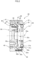
- FIG. 2 is a schematic longitudinal cross-sectional view showing a unit-type strain wave gearing device of Embodiment 2 according to the present invention.
- a unit-type strain wave gearing device 20 (hereinafter simply refers to as a "strain wave gearing device 20"), a strain wave gearing mechanism provided with a cup-shaped externally toothed gear is assembled.
- the strain wave gearing device 20 is provided with a strain wave gearing mechanism 30, a cross roller bearing 40 and an output shaft 50.
- the strain wave gearing mechanism 30 is provided with a wave generator 31, a flexible externally toothed gear 32 which is flexed into a non-circular shape by the wave generator 31, and a rigid internally toothed gear 33 partially meshing with the externally toothed gear 32.
- the externally toothed gear 32 is flexed elliptically by the wave generator 31.
- the wave generator 31 is provided with an elliptical-contoured plug portion 31a and a wave bearing 31c mounted on the elliptical outer peripheral surface 31b of the plug portion 31a.
- the wave bearing 31c is provided with inner and outer rings which are flexible in the radial direction, and is flexed into an elliptical shape by the plug portion 31a.
- the externally toothed gear 32 is of a cup shape and is provided with: a cylindrical barrel part 32a flexible in the radial direction; an annular diaphragm 32b extending inward in the radial direction from an end of the circular cylindrical barrel part 32a on the side of the output shaft 50; an annular rigid boss 32c formed as a continuation from the inner peripheral edge of the diaphragm 32b; and external teeth 32d formed in the outer peripheral surface portion on the other side of the circular cylindrical barrel part 32a.
- the wave generator 31 is positioned on the inner side of the section of the cylindrical barrel part 32a where the external teeth 32d are formed, and this section thereof is flexed into an elliptical shape by the wave generator 31.
- the external teeth 32d are meshed with internal teeth 33a of the internally toothed gear 33 on both ends of the major axis of the elliptically flexed cylindrical barrel part 32a.
- the meshing section 34 between the external teeth 32d and the internal teeth 33a is lubricated by grease.
- the meshing section 34 is coated or filled with a predetermined amount of grease (not shown) beforehand.
- the inner space 32e of the externally toothed gear 32 is also filled with grease, by which the sliding portion between the externally toothed gear 32 and the wave generator 31, and the wave bearing 31c and other portions of the wave generator 31 are lubricated.
- the cross roller bearing 40 is disposed adjacent to the internally toothed gear 33 in the direction of the center axis line 20a.
- the cross roller bearing 40 has an outer ring 41 to which the internally toothed gear 33 is coaxially fixed by fastening bolts.
- the cross roller bearing 40 has an inner ring 42 which is integrally formed in the outer peripheral portion of the output shaft 50 in this example. Specifically, the inner ring 42 and the output shaft 50 are formed by a single component part. A gap between the outer ring 41 and inner ring 42 exposing to the outside of the device is sealed by an oil seal 45.
- the output shaft 50 is of a discoid shape and has an inner-side end face to which the boss 32c of the externally toothed gear 32 is coaxially fixed by fastening bolts. With this, the internally toothed gear 33 fixed to the outer ring 41 and the externally toothed gear 32 fixed to the output shaft 50 which is integrally formed with the inner ring 42 are made to be a state in which both gears can be
- a gap 60 is formed between the externally toothed gear 32 and the cross roller bearing 40.
- the gap 60 includes a first gap portion 61 and a second gap portion 62.
- the first gap portion 61 is formed between the externally toothed gear 32 and portions of the outer ring 41 and the internally toothed gear 32.
- the second gap portion 62 is formed between the externally toothed gear 32 and the inner ring 42.
- the first gap portion 61 is formed between the outer peripheral surface of the cylindrical barrel part 32a of the externally toothed gear 32 and portions that are an end face portion of the outer ring 41 and an inner peripheral surface portion adjacent to the internal teeth 33a of the internally toothed gear 33, the first gap portion extending in the direction of the center axis line 20a along the cylindrical barrel part 32a.
- the first gap portion has one end which is communicated with the meshing section 34 of the external teeth 32d and the internal teeth 33a and has another end which is communicated with the raceway groove 43 between the outer ring 41 and the inner ring 42 and is also communicated with the second gap portion 62.
- the second gap portion 62 is formed between the diaphragm 32b and an annular inner-side end face of the output shaft 50 and extends in the radial direction along the diaphragm 32b.
- the radial outer end of the second gap portion 62 is communicated with the first gap portion 61.
- a plurality of grease-flowing holes 38 are formed in the radial middle section of the diaphragm 32b of the externally toothed gear 32.
- the grease-flowing holes 38 are a plurality of circular through holes formed in the diaphragm 32b at equiangular intervals in the circumferential direction thereof.
- the second gap portion 62 and the inner space 32e of the externally toothed gear 32 are communicated with each other via a plurality of grease-flowing holes 38.
- the inner space 32e is a space formed between the cylindrical barrel part 32a and the wave generator 31. In a case in which the grease-flowing holes 38 are formed in the cylindrical barrel part 32a, the first gap portion 61 and the inner space 32e of the externally toothed gear 32 are communicated via the grease-flowing holes 38.
- the operation of the strain wave gearing device 20 thus constituted will be explained.
- the wave generator 31 When the wave generator 31 is rotated by a motor (not shown), the meshing positions between the externally toothed gear 32 and the internally toothed gear 33 is caused to move in the circumferential direction. Relative rotation between the two gears 32 and 33 is generated in accordance with the difference in the number of teeth between these gears.
- the internally toothed gear 33 is set to be a stationary side, and reduce-speed rotation is outputted from the output shaft 50 linked to the externally toothed gear 32.
- the cylindrical barrel part 32a is repeatedly flexed in the radial direction as the wave generator 31 rotates. This flexion causes to generate pump effect in the meshing section 34 to push grease in the direction toward the diaphragm 32b. The pushed grease flows toward the raceway groove 43 of the cross roller bearing 40 through the first gap portion 61.
- the first gap portion 61 is communicated with the inner space 32e of the externally toothed gear 32 via the second gap portion 62 and the grease-flowing holes 38. Part of the grease pushed out to the first gap portion 61 goes toward the raceway groove 43 and the remaining thereof returns to the inner space 32e of the externally toothed gear 32 passing through the second gap portion 62 and the grease-flowing holes 38. Since the amount of grease reaching the raceway groove 43 of the cross roller bearing 40 can be reduced, it is possible to prevent or suppress grease from leaking out to the unit outside via the oil seal 45.
Landscapes
- Engineering & Computer Science (AREA)
- General Engineering & Computer Science (AREA)
- Mechanical Engineering (AREA)
- Retarders (AREA)
- General Details Of Gearings (AREA)
- Heat Treatment Of Articles (AREA)
- Holo Graphy (AREA)
- Diaphragms For Electromechanical Transducers (AREA)
Claims (2)
- Spannungswellgetriebe (1) vom Einheitentyp, aufweisend:ein starres innenverzahntes Zahnrad (13);ein flexibles außenverzahntes Zahnrad (12);ein Lager (8), das das innenverzahnte Zahnrad (13) und das außenverzahnte Zahnrad (12) in einem im Verhältnis drehbaren Zustand lagert;einen Wellgenerator (11);Fett, das auf oder in einen Kämmbereich (14) der Innenverzahnung (13a) des innenverzahnten Zahnrads (13) und der Außenverzahnung (12d) des außenverzahnten Zahnrads (12) aufgetragen oder eingefüllt wird;einen ersten Spalt (15), der zwischen dem Lager (8) und dem außenverzahnten Zahnrad (12) gebildet ist und der mit dem Kämmbereich (14) und einer Laufbahnrille (8c) des Lagers (8) in Verbindung steht;wobeidas außenverzahnte Zahnrad (12) eine Zylinderform hat und ausgebildet ist mit: einem zylindrischen Trommelteil (12a), der in einer radialen Richtung flexibel ist und koaxial innerhalb des innenverzahnten Zahnrads (13) angeordnet ist; und einer Membran (12b), die sich in einer radialen Richtung von einem ersten Ende des zylindrischen Trommelteils (12a) nach außen erstreckt, wobei die Außenverzahnung (12d) in einem Außenumfangsflächenbereich des zylindrischen Trommelteils (12a) gebildet ist, der der Innenverzahnung (13a) des innenverzahnten Zahnrads (13) zugewandt ist;der Wellgenerator (11) koaxial innerhalb des zylindrischen Trommelteils (12a) des außenverzahnten Zahnrads (12) angeordnet ist, um den zylindrischen Trommelteil (12a) wiederholt in der radialen Richtung zu biegen, um eine Position der Außenverzahnung (12d), die mit der Innenverzahnung (13a) kämmt, in einer Umfangsrichtung zu bewegen;das Lager (8) einen Innenring (8b) hat, der in axialer Richtung zwischen der Membran (12b) und dem innenverzahnten Zahnrad (13) angeordnet ist; undwobei
der erste Spalt (15) einen ersten Spaltbereich (15a) und einen zweiten Spaltbereich (15b) aufweist;der erste Spaltbereich (15a) zwischen dem zylindrischen Trommelteil (12a) des außenverzahnten Zahnrads (12) und dem Innenring (8b) des Lagers (8) gebildet ist, wobei sich der erste Spaltbereich (15a) in der axialen Richtung entlang einer Außenumfangsfläche des zylindrischen Trommelteils (12a) erstreckt und mit dem Kämmbereich (14) in Verbindung steht;der zweite Spaltbereich (15b) zwischen dem Innenring (8b) und der Membran (12b) gebildet ist und sich in einer radialen Richtung entlang der Membran (12b) erstreckt;der zweite Spaltbereich (15b) ein inneres Ende in der radialen Richtung hat, das mit dem ersten Spaltbereich (15a) in Verbindung steht, und ein äußeres Ende in der radialen Richtung hat, das mit einer Laufbahnrille (8c) des Lagers (8) in Verbindung steht; unddadurch gekennzeichnet, dass das Spannungswellgetriebe (1) vom Einheitentyp ferner aufweist:eine Öldichtung, die einen zweiten Spalt (8d) abdichtet, der zwischen dem Außenring (8a) und dem Innenring (8b) des Lagers (8) gebildet ist, wobei der zweite Spalt (8d) eine Verbindung zwischen der Laufbahnrille (8c) und einer Außenseite des Spannungswellgetriebes herstellt; undein Fettflussloch (18), das in dem außenverzahnten Zahnrad (12) gebildet ist, wobeidas Fettflussloch (18) in der Membran (12b) derart gebildet ist, dass es zwischen dem zweiten Spaltbereich (15b) und einem Innenraum des zylindrischen Trommelteils (12a) eine Verbindung herstellt, sodass ein Teil des Fetts, das aus dem Kämmbereich (14) herausgedrückt wird und durch den ersten Spalt (15) in Richtung der Laufbahnrille (8c) des Lagers (8) fließt, durch das Fettflussloch (18) in den Innenraum (12e) des außenverzahnten Zahnrads (12) zurückgeführt wird. - Spannungswellgetriebe (20) vom Einheitentyp, aufweisend:ein starres innenverzahntes Zahnrad (33);ein flexibles außenverzahntes Zahnrad (32);ein Lager (40), das das innenverzahnte Zahnrad (33) und das außenverzahnte Zahnrad (32) in einem im Verhältnis drehbaren Zustand lagert;einen Wellgenerator (31);Fett, das auf oder in einen Kämmbereich (34) der Innenverzahnung (33a) des innenverzahnten Zahnrads (33) und der Außenverzahnung (32d) des außenverzahnten Zahnrads (32) aufgetragen oder eingefüllt wird;einen ersten Spalt (60), der zwischen dem Lager (40) und dem außenverzahnten Zahnrad (32) gebildet ist und der mit dem Kämmbereich (34) und einer Laufbahnrille (43) des Lagers (40) in Verbindung steht;wobeidas außenverzahnte Zahnrad (32) eine Becherform hat und ausgebildet ist mit: einem zylindrischen Trommelteil (32a), der in einer radialen Richtung flexibel ist und koaxial innerhalb des innenverzahnten Zahnrads (33) angeordnet ist; und einer Membran (32b), die sich in einer radialen Richtung von einem ersten Ende des zylindrischen Trommelteils (32a) nach innen erstreckt, wobei die Außenverzahnung (32d) in einem Außenumfangsflächenbereich des zylindrischen Trommelteils (32a) gebildet ist, der der Innenverzahnung (33a) des innenverzahnten Zahnrads zugewandt ist;der Wellgenerator (31) koaxial innerhalb des zylindrischen Trommelteils (32a) des außenverzahnten Zahnrads (32) angeordnet ist, um den zylindrischen Trommelteil (32a) wiederholt in der radialen Richtung zu biegen, um eine Position der Außenverzahnung (32d), die mit der Innenverzahnung (33a) kämmt, in einer Umfangsrichtung zu bewegen; unddas innenverzahnte Zahnrad (33) und ein Außenring (41) des Lagers (40) in axialer Richtung benachbart zueinander angeordnet sind; undwobeider erste Spalt (60) einen ersten Spaltbereich (61) und einen zweiten Spaltbereich (62) aufweist;der erste Spaltbereich (61) zwischen dem zylindrischen Trommelteil (32a) des außenverzahnten Zahnrads (32) und Bereichen des Außenrings (41) des Lagers (40) und einer Innenumfangsfläche des innenverzahnten Zahnrads (33) gebildet ist;der zweite Spaltbereich (62) zwischen der Membran (32b) und einem Innenring (42) des Lagers (40) gebildet ist;der erste Spaltbereich (61) sich in der axialen Richtung entlang einer Außenumfangsfläche des zylindrischen Trommelteils (32a) erstreckt;der erste Spaltbereich (61) ein Ende in axialer Richtung hat, das mit dem Kämmbereich (34) in Verbindung steht, und ein anderes Ende hat, das mit der Laufbahnrille (43) des Lagers (40) in Verbindung steht;der zweite Spaltbereich (62) sich in radialer Richtung entlang der Membran (32b) erstreckt;der zweite Spaltbereich (62) ein äußeres Ende in radialer Richtung hat, das mit dem ersten Spaltbereich (61) in Verbindung steht;dadurch gekennzeichnet, dass das Spannungswellgetriebe (20) vom Einheitentyp ferner aufweist:eine Öldichtung (45), die einen zweiten Spalt abdichtet, der zwischen dem Außenring (41) und dem Innenring (42) des Lagers (40) gebildet ist, wobei der zweite Spalt eine Verbindung zwischen der Laufbahnrille (43) und einer Außenseite des Spannungswellgetriebes herstellt; undein Fettflussloch, das in dem außenverzahnten Zahnrad (42) gebildet ist, wobeidas Fettflussloch (38) in der Membran (32b) gebildet ist und zwischen dem zweiten Spaltbereich (62) und einem Innenraum (32e) des zylindrischen Trommelteils (32a) eine Verbindung herstellt, sodass ein Teil des Fetts, das aus dem Kämmbereich (34) herausgedrückt wird und durch den ersten Spaltbereich (61) in Richtung der Laufbahnrille (43) des Lagers (40) fließt, durch das Fettflussloch (38) in den Innenraum (32e) des außenverzahnten Zahnrads (32) zurückgeführt wird.
Applications Claiming Priority (1)
| Application Number | Priority Date | Filing Date | Title |
|---|---|---|---|
| PCT/JP2018/042561 WO2020100309A1 (ja) | 2018-11-16 | 2018-11-16 | ユニットタイプの波動歯車装置 |
Publications (3)
| Publication Number | Publication Date |
|---|---|
| EP3882483A1 EP3882483A1 (de) | 2021-09-22 |
| EP3882483A4 EP3882483A4 (de) | 2022-04-27 |
| EP3882483B1 true EP3882483B1 (de) | 2025-06-18 |
Family
ID=70731111
Family Applications (1)
| Application Number | Title | Priority Date | Filing Date |
|---|---|---|---|
| EP18940134.2A Active EP3882483B1 (de) | 2018-11-16 | 2018-11-16 | Spannungswellengetriebe vom einheitentyp |
Country Status (7)
| Country | Link |
|---|---|
| US (1) | US11566695B2 (de) |
| EP (1) | EP3882483B1 (de) |
| JP (1) | JP7032011B2 (de) |
| KR (1) | KR102442871B1 (de) |
| CN (1) | CN112969866B (de) |
| TW (1) | TWI819101B (de) |
| WO (1) | WO2020100309A1 (de) |
Families Citing this family (6)
| Publication number | Priority date | Publication date | Assignee | Title |
|---|---|---|---|---|
| US11441660B2 (en) * | 2018-06-19 | 2022-09-13 | Harmonic Drive Systems Inc. | Hollow strain-wave gear device |
| US11566695B2 (en) * | 2018-11-16 | 2023-01-31 | Harmonic Drive Systems Inc. | Unit-type strain wave gearing device |
| JP7535950B2 (ja) * | 2021-01-04 | 2024-08-19 | 住友重機械工業株式会社 | 撓み噛合い式歯車装置 |
| JP3233524U (ja) | 2021-06-04 | 2021-08-12 | 株式会社ハーモニック・ドライブ・システムズ | ユニットタイプの波動歯車装置 |
| WO2023102830A1 (en) * | 2021-12-09 | 2023-06-15 | Abb Schweiz Ag | Harmonic reducer |
| NO20230767A1 (en) * | 2023-07-07 | 2025-01-08 | Eltorque As | Hollow actuator with strain wave gear and self-lock for emergency operation |
Citations (1)
| Publication number | Priority date | Publication date | Assignee | Title |
|---|---|---|---|---|
| WO2014091522A1 (ja) * | 2012-12-12 | 2014-06-19 | 株式会社ハーモニック・ドライブ・システムズ | 入力軸受け付き波動歯車ユニット |
Family Cites Families (17)
| Publication number | Priority date | Publication date | Assignee | Title |
|---|---|---|---|---|
| JPS6012756U (ja) * | 1983-07-07 | 1985-01-28 | 三菱電機株式会社 | 減速装置 |
| JPH0545881Y2 (de) * | 1989-01-05 | 1993-11-29 | ||
| JPH0989053A (ja) * | 1995-09-29 | 1997-03-31 | Harmonic Drive Syst Ind Co Ltd | 波動歯車装置 |
| JP3835709B2 (ja) * | 1996-03-18 | 2006-10-18 | 株式会社ハーモニック・ドライブ・システムズ | 撓み噛み合い式歯車装置の潤滑機構 |
| JPH09303497A (ja) * | 1996-05-21 | 1997-11-25 | Harmonic Drive Syst Ind Co Ltd | シルクハット型撓み噛み合い式歯車装置 |
| DE19853802C2 (de) * | 1998-11-21 | 2001-02-22 | Horst Scholz Gmbh & Co Kg | Spannungswellengetriebe |
| JP4877804B2 (ja) | 2007-03-08 | 2012-02-15 | 株式会社ハーモニック・ドライブ・システムズ | 波動歯車減速機の潤滑方法および回転テーブル装置 |
| JP5917362B2 (ja) * | 2012-10-24 | 2016-05-11 | 住友重機械工業株式会社 | 動力伝達装置 |
| JP5839524B2 (ja) * | 2013-06-20 | 2016-01-06 | 株式会社ハーモニック・ドライブ・システムズ | 中空型波動歯車ユニット |
| JP3187367U (ja) * | 2013-09-11 | 2013-11-21 | 株式会社ハーモニック・ドライブ・システムズ | カップ型波動歯車装置ユニット |
| DE112013005396B4 (de) * | 2013-09-12 | 2021-01-07 | Harmonic Drive Systems Inc. | Verformungswellgetriebeeinheit |
| CN205877138U (zh) * | 2016-07-26 | 2017-01-11 | 广州市昊志机电股份有限公司 | 一种采用杯形柔轮的中空型谐波减速器 |
| CN107795662B (zh) * | 2016-08-31 | 2020-06-19 | 比亚迪股份有限公司 | 用于谐波减速器的刚轮、谐波减速器以及机器人 |
| US11441660B2 (en) * | 2018-06-19 | 2022-09-13 | Harmonic Drive Systems Inc. | Hollow strain-wave gear device |
| EP3690281B1 (de) * | 2018-09-20 | 2022-03-09 | Harmonic Drive Systems Inc. | Einheitswellengetriebevorrichtung |
| US11566695B2 (en) * | 2018-11-16 | 2023-01-31 | Harmonic Drive Systems Inc. | Unit-type strain wave gearing device |
| JP6793867B1 (ja) * | 2020-06-29 | 2020-12-02 | 株式会社ハーモニック・ドライブ・システムズ | 波動歯車装置ユニット |
-
2018
- 2018-11-16 US US17/281,736 patent/US11566695B2/en active Active
- 2018-11-16 EP EP18940134.2A patent/EP3882483B1/de active Active
- 2018-11-16 JP JP2020556578A patent/JP7032011B2/ja active Active
- 2018-11-16 CN CN201880099111.9A patent/CN112969866B/zh active Active
- 2018-11-16 WO PCT/JP2018/042561 patent/WO2020100309A1/ja not_active Ceased
- 2018-11-16 KR KR1020217013039A patent/KR102442871B1/ko active Active
-
2019
- 2019-09-23 TW TW108134180A patent/TWI819101B/zh active
Patent Citations (1)
| Publication number | Priority date | Publication date | Assignee | Title |
|---|---|---|---|---|
| WO2014091522A1 (ja) * | 2012-12-12 | 2014-06-19 | 株式会社ハーモニック・ドライブ・システムズ | 入力軸受け付き波動歯車ユニット |
Also Published As
| Publication number | Publication date |
|---|---|
| TWI819101B (zh) | 2023-10-21 |
| US11566695B2 (en) | 2023-01-31 |
| KR102442871B1 (ko) | 2022-09-13 |
| JPWO2020100309A1 (ja) | 2021-09-02 |
| TW202035893A (zh) | 2020-10-01 |
| CN112969866A (zh) | 2021-06-15 |
| JP7032011B2 (ja) | 2022-03-08 |
| US20210396303A1 (en) | 2021-12-23 |
| KR20210063425A (ko) | 2021-06-01 |
| CN112969866B (zh) | 2024-09-27 |
| EP3882483A4 (de) | 2022-04-27 |
| EP3882483A1 (de) | 2021-09-22 |
| WO2020100309A1 (ja) | 2020-05-22 |
Similar Documents
| Publication | Publication Date | Title |
|---|---|---|
| EP3882483B1 (de) | Spannungswellengetriebe vom einheitentyp | |
| EP3674579B1 (de) | Wellenbewegungsgetriebevorrichtung mit einem teil zur verhinderung der vermischung von schmiermitteln | |
| JP6909141B2 (ja) | 撓み噛合い式歯車装置 | |
| US8858383B2 (en) | Gear transmission | |
| EP2119941A1 (de) | Getriebevorrichtung | |
| KR20220002924U (ko) | 유닛타입의 파동기어장치 | |
| KR20190092262A (ko) | 휨맞물림식 기어장치 | |
| JP6021694B2 (ja) | 車輪駆動装置のシリーズ | |
| TW201418598A (zh) | 齒輪傳動裝置及使用其之曲柄軸構造體 | |
| CN110185745B (zh) | 齿轮装置系列及其构建方法、以及齿轮装置组的制造方法 | |
| US11493112B2 (en) | Speed reducer | |
| EP4019806A1 (de) | Einheitswellengetriebevorrichtung | |
| JP7253089B2 (ja) | 撓み噛合い式歯車装置 | |
| JP2022536629A (ja) | 波動歯車装置 | |
| JP5339743B2 (ja) | 歯車装置 | |
| JP2009210032A (ja) | 歯車装置 | |
| JP2022072248A (ja) | 遊星歯車用軸受装置及び遊星歯車装置 | |
| JP2022105356A (ja) | 撓み噛合い式歯車装置 | |
| JP2009210031A (ja) | 歯車装置 |
Legal Events
| Date | Code | Title | Description |
|---|---|---|---|
| STAA | Information on the status of an ep patent application or granted ep patent |
Free format text: STATUS: THE INTERNATIONAL PUBLICATION HAS BEEN MADE |
|
| PUAI | Public reference made under article 153(3) epc to a published international application that has entered the european phase |
Free format text: ORIGINAL CODE: 0009012 |
|
| STAA | Information on the status of an ep patent application or granted ep patent |
Free format text: STATUS: REQUEST FOR EXAMINATION WAS MADE |
|
| 17P | Request for examination filed |
Effective date: 20210315 |
|
| AK | Designated contracting states |
Kind code of ref document: A1 Designated state(s): AL AT BE BG CH CY CZ DE DK EE ES FI FR GB GR HR HU IE IS IT LI LT LU LV MC MK MT NL NO PL PT RO RS SE SI SK SM TR |
|
| DAV | Request for validation of the european patent (deleted) | ||
| DAX | Request for extension of the european patent (deleted) | ||
| REG | Reference to a national code |
Ref country code: DE Ref legal event code: R079 Free format text: PREVIOUS MAIN CLASS: F16H0001320000 Ipc: F16H0057040000 Ref document number: 602018082813 Country of ref document: DE |
|
| A4 | Supplementary search report drawn up and despatched |
Effective date: 20220329 |
|
| RIC1 | Information provided on ipc code assigned before grant |
Ipc: F16H 49/00 20060101ALI20220323BHEP Ipc: F16H 57/04 20100101AFI20220323BHEP |
|
| STAA | Information on the status of an ep patent application or granted ep patent |
Free format text: STATUS: EXAMINATION IS IN PROGRESS |
|
| 17Q | First examination report despatched |
Effective date: 20240311 |
|
| GRAP | Despatch of communication of intention to grant a patent |
Free format text: ORIGINAL CODE: EPIDOSNIGR1 |
|
| STAA | Information on the status of an ep patent application or granted ep patent |
Free format text: STATUS: GRANT OF PATENT IS INTENDED |
|
| INTG | Intention to grant announced |
Effective date: 20250115 |
|
| GRAS | Grant fee paid |
Free format text: ORIGINAL CODE: EPIDOSNIGR3 |
|
| GRAA | (expected) grant |
Free format text: ORIGINAL CODE: 0009210 |
|
| STAA | Information on the status of an ep patent application or granted ep patent |
Free format text: STATUS: THE PATENT HAS BEEN GRANTED |
|
| AK | Designated contracting states |
Kind code of ref document: B1 Designated state(s): AL AT BE BG CH CY CZ DE DK EE ES FI FR GB GR HR HU IE IS IT LI LT LU LV MC MK MT NL NO PL PT RO RS SE SI SK SM TR |
|
| REG | Reference to a national code |
Ref country code: GB Ref legal event code: FG4D |
|
| REG | Reference to a national code |
Ref country code: CH Ref legal event code: EP |
|
| REG | Reference to a national code |
Ref country code: DE Ref legal event code: R096 Ref document number: 602018082813 Country of ref document: DE |
|
| REG | Reference to a national code |
Ref country code: CH Ref legal event code: EP |
|
| REG | Reference to a national code |
Ref country code: IE Ref legal event code: FG4D |
|
| PG25 | Lapsed in a contracting state [announced via postgrant information from national office to epo] |
Ref country code: FI Free format text: LAPSE BECAUSE OF FAILURE TO SUBMIT A TRANSLATION OF THE DESCRIPTION OR TO PAY THE FEE WITHIN THE PRESCRIBED TIME-LIMIT Effective date: 20250618 |
|
| REG | Reference to a national code |
Ref country code: LT Ref legal event code: MG9D |
|
| PG25 | Lapsed in a contracting state [announced via postgrant information from national office to epo] |
Ref country code: GR Free format text: LAPSE BECAUSE OF FAILURE TO SUBMIT A TRANSLATION OF THE DESCRIPTION OR TO PAY THE FEE WITHIN THE PRESCRIBED TIME-LIMIT Effective date: 20250919 Ref country code: NO Free format text: LAPSE BECAUSE OF FAILURE TO SUBMIT A TRANSLATION OF THE DESCRIPTION OR TO PAY THE FEE WITHIN THE PRESCRIBED TIME-LIMIT Effective date: 20250918 |
|
| PG25 | Lapsed in a contracting state [announced via postgrant information from national office to epo] |
Ref country code: BG Free format text: LAPSE BECAUSE OF FAILURE TO SUBMIT A TRANSLATION OF THE DESCRIPTION OR TO PAY THE FEE WITHIN THE PRESCRIBED TIME-LIMIT Effective date: 20250618 |
|
| PG25 | Lapsed in a contracting state [announced via postgrant information from national office to epo] |
Ref country code: HR Free format text: LAPSE BECAUSE OF FAILURE TO SUBMIT A TRANSLATION OF THE DESCRIPTION OR TO PAY THE FEE WITHIN THE PRESCRIBED TIME-LIMIT Effective date: 20250618 |
|
| PG25 | Lapsed in a contracting state [announced via postgrant information from national office to epo] |
Ref country code: RS Free format text: LAPSE BECAUSE OF FAILURE TO SUBMIT A TRANSLATION OF THE DESCRIPTION OR TO PAY THE FEE WITHIN THE PRESCRIBED TIME-LIMIT Effective date: 20250918 |
|
| REG | Reference to a national code |
Ref country code: NL Ref legal event code: MP Effective date: 20250618 |
|
| PG25 | Lapsed in a contracting state [announced via postgrant information from national office to epo] |
Ref country code: LV Free format text: LAPSE BECAUSE OF FAILURE TO SUBMIT A TRANSLATION OF THE DESCRIPTION OR TO PAY THE FEE WITHIN THE PRESCRIBED TIME-LIMIT Effective date: 20250618 |
|
| PG25 | Lapsed in a contracting state [announced via postgrant information from national office to epo] |
Ref country code: NL Free format text: LAPSE BECAUSE OF FAILURE TO SUBMIT A TRANSLATION OF THE DESCRIPTION OR TO PAY THE FEE WITHIN THE PRESCRIBED TIME-LIMIT Effective date: 20250618 |
|
| PG25 | Lapsed in a contracting state [announced via postgrant information from national office to epo] |
Ref country code: PT Free format text: LAPSE BECAUSE OF FAILURE TO SUBMIT A TRANSLATION OF THE DESCRIPTION OR TO PAY THE FEE WITHIN THE PRESCRIBED TIME-LIMIT Effective date: 20251020 |
|
| REG | Reference to a national code |
Ref country code: AT Ref legal event code: MK05 Ref document number: 1804433 Country of ref document: AT Kind code of ref document: T Effective date: 20250618 |
|
| PG25 | Lapsed in a contracting state [announced via postgrant information from national office to epo] |
Ref country code: IS Free format text: LAPSE BECAUSE OF FAILURE TO SUBMIT A TRANSLATION OF THE DESCRIPTION OR TO PAY THE FEE WITHIN THE PRESCRIBED TIME-LIMIT Effective date: 20251018 |
|
| PGFP | Annual fee paid to national office [announced via postgrant information from national office to epo] |
Ref country code: DE Payment date: 20250930 Year of fee payment: 8 |
|
| PG25 | Lapsed in a contracting state [announced via postgrant information from national office to epo] |
Ref country code: AT Free format text: LAPSE BECAUSE OF FAILURE TO SUBMIT A TRANSLATION OF THE DESCRIPTION OR TO PAY THE FEE WITHIN THE PRESCRIBED TIME-LIMIT Effective date: 20250618 Ref country code: SM Free format text: LAPSE BECAUSE OF FAILURE TO SUBMIT A TRANSLATION OF THE DESCRIPTION OR TO PAY THE FEE WITHIN THE PRESCRIBED TIME-LIMIT Effective date: 20250618 |
|
| PG25 | Lapsed in a contracting state [announced via postgrant information from national office to epo] |
Ref country code: CZ Free format text: LAPSE BECAUSE OF FAILURE TO SUBMIT A TRANSLATION OF THE DESCRIPTION OR TO PAY THE FEE WITHIN THE PRESCRIBED TIME-LIMIT Effective date: 20250618 |
|
| PG25 | Lapsed in a contracting state [announced via postgrant information from national office to epo] |
Ref country code: PL Free format text: LAPSE BECAUSE OF FAILURE TO SUBMIT A TRANSLATION OF THE DESCRIPTION OR TO PAY THE FEE WITHIN THE PRESCRIBED TIME-LIMIT Effective date: 20250618 |
|
| PG25 | Lapsed in a contracting state [announced via postgrant information from national office to epo] |
Ref country code: EE Free format text: LAPSE BECAUSE OF FAILURE TO SUBMIT A TRANSLATION OF THE DESCRIPTION OR TO PAY THE FEE WITHIN THE PRESCRIBED TIME-LIMIT Effective date: 20250618 |
|
| PG25 | Lapsed in a contracting state [announced via postgrant information from national office to epo] |
Ref country code: RO Free format text: LAPSE BECAUSE OF FAILURE TO SUBMIT A TRANSLATION OF THE DESCRIPTION OR TO PAY THE FEE WITHIN THE PRESCRIBED TIME-LIMIT Effective date: 20250618 Ref country code: SK Free format text: LAPSE BECAUSE OF FAILURE TO SUBMIT A TRANSLATION OF THE DESCRIPTION OR TO PAY THE FEE WITHIN THE PRESCRIBED TIME-LIMIT Effective date: 20250618 |
|
| PG25 | Lapsed in a contracting state [announced via postgrant information from national office to epo] |
Ref country code: ES Free format text: LAPSE BECAUSE OF FAILURE TO SUBMIT A TRANSLATION OF THE DESCRIPTION OR TO PAY THE FEE WITHIN THE PRESCRIBED TIME-LIMIT Effective date: 20250618 |