EP3880425B1 - Verfahren zur herstellung eines bauteils sowie spritzgiessvorrichtung - Google Patents
Verfahren zur herstellung eines bauteils sowie spritzgiessvorrichtung Download PDFInfo
- Publication number
- EP3880425B1 EP3880425B1 EP19798616.9A EP19798616A EP3880425B1 EP 3880425 B1 EP3880425 B1 EP 3880425B1 EP 19798616 A EP19798616 A EP 19798616A EP 3880425 B1 EP3880425 B1 EP 3880425B1
- Authority
- EP
- European Patent Office
- Prior art keywords
- base body
- embossing
- tool
- foil
- injection molding
- Prior art date
- Legal status (The legal status is an assumption and is not a legal conclusion. Google has not performed a legal analysis and makes no representation as to the accuracy of the status listed.)
- Active
Links
Images


Classifications
-
- B—PERFORMING OPERATIONS; TRANSPORTING
- B29—WORKING OF PLASTICS; WORKING OF SUBSTANCES IN A PLASTIC STATE IN GENERAL
- B29C—SHAPING OR JOINING OF PLASTICS; SHAPING OF MATERIAL IN A PLASTIC STATE, NOT OTHERWISE PROVIDED FOR; AFTER-TREATMENT OF THE SHAPED PRODUCTS, e.g. REPAIRING
- B29C45/00—Injection moulding, i.e. forcing the required volume of moulding material through a nozzle into a closed mould; Apparatus therefor
- B29C45/0053—Injection moulding, i.e. forcing the required volume of moulding material through a nozzle into a closed mould; Apparatus therefor combined with a final operation, e.g. shaping
-
- B—PERFORMING OPERATIONS; TRANSPORTING
- B29—WORKING OF PLASTICS; WORKING OF SUBSTANCES IN A PLASTIC STATE IN GENERAL
- B29C—SHAPING OR JOINING OF PLASTICS; SHAPING OF MATERIAL IN A PLASTIC STATE, NOT OTHERWISE PROVIDED FOR; AFTER-TREATMENT OF THE SHAPED PRODUCTS, e.g. REPAIRING
- B29C45/00—Injection moulding, i.e. forcing the required volume of moulding material through a nozzle into a closed mould; Apparatus therefor
- B29C45/14—Injection moulding, i.e. forcing the required volume of moulding material through a nozzle into a closed mould; Apparatus therefor incorporating preformed parts or layers, e.g. injection moulding around inserts or for coating articles
- B29C45/14336—Coating a portion of the article, e.g. the edge of the article
-
- B—PERFORMING OPERATIONS; TRANSPORTING
- B29—WORKING OF PLASTICS; WORKING OF SUBSTANCES IN A PLASTIC STATE IN GENERAL
- B29C—SHAPING OR JOINING OF PLASTICS; SHAPING OF MATERIAL IN A PLASTIC STATE, NOT OTHERWISE PROVIDED FOR; AFTER-TREATMENT OF THE SHAPED PRODUCTS, e.g. REPAIRING
- B29C45/00—Injection moulding, i.e. forcing the required volume of moulding material through a nozzle into a closed mould; Apparatus therefor
- B29C45/14—Injection moulding, i.e. forcing the required volume of moulding material through a nozzle into a closed mould; Apparatus therefor incorporating preformed parts or layers, e.g. injection moulding around inserts or for coating articles
- B29C45/14688—Coating articles provided with a decoration
-
- B—PERFORMING OPERATIONS; TRANSPORTING
- B29—WORKING OF PLASTICS; WORKING OF SUBSTANCES IN A PLASTIC STATE IN GENERAL
- B29C—SHAPING OR JOINING OF PLASTICS; SHAPING OF MATERIAL IN A PLASTIC STATE, NOT OTHERWISE PROVIDED FOR; AFTER-TREATMENT OF THE SHAPED PRODUCTS, e.g. REPAIRING
- B29C45/00—Injection moulding, i.e. forcing the required volume of moulding material through a nozzle into a closed mould; Apparatus therefor
- B29C45/14—Injection moulding, i.e. forcing the required volume of moulding material through a nozzle into a closed mould; Apparatus therefor incorporating preformed parts or layers, e.g. injection moulding around inserts or for coating articles
- B29C45/14827—Injection moulding, i.e. forcing the required volume of moulding material through a nozzle into a closed mould; Apparatus therefor incorporating preformed parts or layers, e.g. injection moulding around inserts or for coating articles using a transfer foil detachable from the insert
-
- B—PERFORMING OPERATIONS; TRANSPORTING
- B29—WORKING OF PLASTICS; WORKING OF SUBSTANCES IN A PLASTIC STATE IN GENERAL
- B29C—SHAPING OR JOINING OF PLASTICS; SHAPING OF MATERIAL IN A PLASTIC STATE, NOT OTHERWISE PROVIDED FOR; AFTER-TREATMENT OF THE SHAPED PRODUCTS, e.g. REPAIRING
- B29C45/00—Injection moulding, i.e. forcing the required volume of moulding material through a nozzle into a closed mould; Apparatus therefor
- B29C45/16—Making multilayered or multicoloured articles
- B29C45/1635—Making multilayered or multicoloured articles using displaceable mould parts, e.g. retractable partition between adjacent mould cavities
-
- B—PERFORMING OPERATIONS; TRANSPORTING
- B29—WORKING OF PLASTICS; WORKING OF SUBSTANCES IN A PLASTIC STATE IN GENERAL
- B29C—SHAPING OR JOINING OF PLASTICS; SHAPING OF MATERIAL IN A PLASTIC STATE, NOT OTHERWISE PROVIDED FOR; AFTER-TREATMENT OF THE SHAPED PRODUCTS, e.g. REPAIRING
- B29C45/00—Injection moulding, i.e. forcing the required volume of moulding material through a nozzle into a closed mould; Apparatus therefor
- B29C45/16—Making multilayered or multicoloured articles
- B29C45/1671—Making multilayered or multicoloured articles with an insert
-
- B—PERFORMING OPERATIONS; TRANSPORTING
- B29—WORKING OF PLASTICS; WORKING OF SUBSTANCES IN A PLASTIC STATE IN GENERAL
- B29C—SHAPING OR JOINING OF PLASTICS; SHAPING OF MATERIAL IN A PLASTIC STATE, NOT OTHERWISE PROVIDED FOR; AFTER-TREATMENT OF THE SHAPED PRODUCTS, e.g. REPAIRING
- B29C45/00—Injection moulding, i.e. forcing the required volume of moulding material through a nozzle into a closed mould; Apparatus therefor
- B29C45/17—Component parts, details or accessories; Auxiliary operations
- B29C45/64—Mould opening, closing or clamping devices
-
- B—PERFORMING OPERATIONS; TRANSPORTING
- B41—PRINTING; LINING MACHINES; TYPEWRITERS; STAMPS
- B41F—PRINTING MACHINES OR PRESSES
- B41F16/00—Transfer printing apparatus
- B41F16/0006—Transfer printing apparatus for printing from an inked or preprinted foil or band
- B41F16/004—Presses of the reciprocating type
- B41F16/0053—Presses of the reciprocating type with means for applying print under pressure only, e.g. using pressure sensitive adhesive
-
- B—PERFORMING OPERATIONS; TRANSPORTING
- B41—PRINTING; LINING MACHINES; TYPEWRITERS; STAMPS
- B41F—PRINTING MACHINES OR PRESSES
- B41F16/00—Transfer printing apparatus
- B41F16/0006—Transfer printing apparatus for printing from an inked or preprinted foil or band
- B41F16/0073—Transfer printing apparatus for printing from an inked or preprinted foil or band with means for printing on specific materials or products
- B41F16/008—Transfer printing apparatus for printing from an inked or preprinted foil or band with means for printing on specific materials or products for printing on three-dimensional articles
-
- B—PERFORMING OPERATIONS; TRANSPORTING
- B29—WORKING OF PLASTICS; WORKING OF SUBSTANCES IN A PLASTIC STATE IN GENERAL
- B29C—SHAPING OR JOINING OF PLASTICS; SHAPING OF MATERIAL IN A PLASTIC STATE, NOT OTHERWISE PROVIDED FOR; AFTER-TREATMENT OF THE SHAPED PRODUCTS, e.g. REPAIRING
- B29C45/00—Injection moulding, i.e. forcing the required volume of moulding material through a nozzle into a closed mould; Apparatus therefor
- B29C45/0053—Injection moulding, i.e. forcing the required volume of moulding material through a nozzle into a closed mould; Apparatus therefor combined with a final operation, e.g. shaping
- B29C2045/0079—Injection moulding, i.e. forcing the required volume of moulding material through a nozzle into a closed mould; Apparatus therefor combined with a final operation, e.g. shaping applying a coating or covering
-
- B—PERFORMING OPERATIONS; TRANSPORTING
- B29—WORKING OF PLASTICS; WORKING OF SUBSTANCES IN A PLASTIC STATE IN GENERAL
- B29C—SHAPING OR JOINING OF PLASTICS; SHAPING OF MATERIAL IN A PLASTIC STATE, NOT OTHERWISE PROVIDED FOR; AFTER-TREATMENT OF THE SHAPED PRODUCTS, e.g. REPAIRING
- B29C45/00—Injection moulding, i.e. forcing the required volume of moulding material through a nozzle into a closed mould; Apparatus therefor
- B29C45/16—Making multilayered or multicoloured articles
- B29C45/1635—Making multilayered or multicoloured articles using displaceable mould parts, e.g. retractable partition between adjacent mould cavities
- B29C2045/1637—Making multilayered or multicoloured articles using displaceable mould parts, e.g. retractable partition between adjacent mould cavities the first injected part and the movable mould part being movable together
-
- B—PERFORMING OPERATIONS; TRANSPORTING
- B29—WORKING OF PLASTICS; WORKING OF SUBSTANCES IN A PLASTIC STATE IN GENERAL
- B29C—SHAPING OR JOINING OF PLASTICS; SHAPING OF MATERIAL IN A PLASTIC STATE, NOT OTHERWISE PROVIDED FOR; AFTER-TREATMENT OF THE SHAPED PRODUCTS, e.g. REPAIRING
- B29C45/00—Injection moulding, i.e. forcing the required volume of moulding material through a nozzle into a closed mould; Apparatus therefor
- B29C45/16—Making multilayered or multicoloured articles
- B29C45/1671—Making multilayered or multicoloured articles with an insert
- B29C2045/1673—Making multilayered or multicoloured articles with an insert injecting the first layer, then feeding the insert, then injecting the second layer
-
- B—PERFORMING OPERATIONS; TRANSPORTING
- B29—WORKING OF PLASTICS; WORKING OF SUBSTANCES IN A PLASTIC STATE IN GENERAL
- B29C—SHAPING OR JOINING OF PLASTICS; SHAPING OF MATERIAL IN A PLASTIC STATE, NOT OTHERWISE PROVIDED FOR; AFTER-TREATMENT OF THE SHAPED PRODUCTS, e.g. REPAIRING
- B29C2945/00—Indexing scheme relating to injection moulding, i.e. forcing the required volume of moulding material through a nozzle into a closed mould
- B29C2945/76—Measuring, controlling or regulating
- B29C2945/76451—Measurement means
- B29C2945/76461—Optical, e.g. laser
- B29C2945/76464—Optical, e.g. laser cameras
-
- B—PERFORMING OPERATIONS; TRANSPORTING
- B29—WORKING OF PLASTICS; WORKING OF SUBSTANCES IN A PLASTIC STATE IN GENERAL
- B29K—INDEXING SCHEME ASSOCIATED WITH SUBCLASSES B29B, B29C OR B29D, RELATING TO MOULDING MATERIALS OR TO MATERIALS FOR MOULDS, REINFORCEMENTS, FILLERS OR PREFORMED PARTS, e.g. INSERTS
- B29K2075/00—Use of PU, i.e. polyureas or polyurethanes or derivatives thereof, as moulding material
- B29K2075/02—Polyureas
Definitions
- the invention relates to a method for producing a component.
- a hot stamping foil is used to produce a plastic trim part. This hot stamping foil is fed from top to bottom through an injection molding tool and the foil is clamped between the tool halves when the tool is closed. When the melt is injected, the pressure of the melt presses the foil against the wall of the cavity. After cooling, the polyester carrier foil of the hot stamping foil is then peeled off the component decorated with the transfer layer of the hot stamping foil.
- the disadvantage here is the limited possibilities for decoration, due to the large application area determined by the respective injection mold half, as well as the high pressure and high temperatures to which the decorative layers of the hot stamping foil are exposed during application within the injection mold.
- emboss a body for decoration with a transfer layer of hot stamping foil As for example in the EN 102012109315 A1 As described, such an embossing device has a holding device as an embossing holder, in which the workpiece to be embossed is clamped. Furthermore, an embossing tool is provided, which presses a hot stamping foil against the surfaces of the workpiece to be decorated, whereby the embossing pressure is built up between the embossing holder and the embossing tool.
- JPS63135214A describes a method for producing a component in which an identification element in the form of a badge is embedded in a sandwich-like manner between two layers of plastic produced by injection molding. In the disclosed method, the component remains in the same half of an injection mold during several production steps.
- the invention is based on the object of specifying a method for producing a component which has improved functions and/or decorative properties and can nevertheless be produced cost-effectively.
- an injection molding device for producing a component according to the method described above is disclosed, in which the injection molding device has at least one first injection molding station and at least one stamping station.
- the injection molding device further has at least one first mold half with a first mold cavity and at least one second mold half.
- the at least one first injection molding station has a closing device which is designed to close an injection molding tool comprising the first mold half or one of the first mold halves and the at least one second mold half to form a first injection molding cavity, and to open the injection molding tool.
- the at least one first Injection molding station has an injection unit for introducing a first plastic material forming a base body into the first injection molding cavity.
- the embossing station has an embossing unit for embossing one or more first film elements onto at least a partial area of the surface of the base body, which is arranged in the first tool cavity of the first tool mold half following the contour, wherein the first tool mold half of the embossing unit serves as an embossing receptacle for embossing the one or more first film elements, wherein the injection molding device has at least a second injection molding station for applying a cover layer made of a second plastic material by means of flooding.
- the embossing process is integrated into the injection molding machine and the tool mold half, which in particular molds the so-called underside of the component, is used as the embossing holder. This avoids having to move the component before embossing is carried out and instead it is held in the injection molding cavity even during embossing.
- the embossing holder is used for embossing. This ensures that the embossing holder is precisely adapted to the component and that all component tolerances are accurately molded. This means that embossing can also be carried out before the component has completely cooled down and before it is demolded, which means that the component tolerances that occur due to thermal distortion and any mechanical distortion during demolding do not have a negative impact on the embossing process and therefore on the embossing quality. It has also been shown that the coordination work to optimize the embossing process can be significantly reduced and the embossing quality and process stability can be significantly increased.
- a further step involves applying a cover layer made of a second plastic material, which is carried out by flooding.
- a cover layer made of a second plastic material, which is carried out by flooding.
- the base body When carrying out this step, the base body preferably remains contour-following in the first tool cavity of the first tool mold half.
- the first tool mold half is thus not only additionally used to form the embossing holder for embossing the one or more first film elements, but also forms the component holder for applying the cover layer.
- a second injection molding cavity is preferably formed by means of one or more third mold halves, and the second plastic material is introduced into the second injection molding cavity.
- the one or more third mold halves are preferably sealed against the base body, the one or more first film elements and/or the first mold half, which enables a correspondingly large range of variation with regard to the areas that are provided with the cover layer.
- the cover layer in such a way that the one or more film elements are encapsulated between the base body and the cover layer.
- This encapsulation makes it possible to protect the film elements well against environmental influences or to achieve particularly advantageous optical and/or functional effects through the interactions caused by this.
- the cover layer is also possible for the cover layer to be applied in such a way that the cover layer completely overlaps the one or more first film elements and/or the first partial area of the surface of the base body. This makes it possible, for example, to create a correspondingly closed protective layer or decorative layer in the corresponding partial area of the surface of the component, which is intended, for example, to form the outside of the component exposed to the weather.
- the cover layer can be applied in such a way that the cover layer only partially overlaps the one or more first film elements and/or the first partial area of the surface of the base body.
- This partial overlap can also be made in register with the one or more first film elements and/or the first partial area of the surface of the base body in order to create functional and/or decorative elements in register with the cover layer, which interact with and/or complement decorative elements and/or functions of the first film elements.
- Register or registration accuracy or registration accuracy is the positional accuracy of two or more elements and/or layers relative to each other.
- the registration accuracy should be within a specified tolerance and as low as possible.
- the registration accuracy of several elements, sub-areas, in particular one or more first sub-areas, Films and/or layers to one another is an important feature in order to increase process reliability.
- the precise positioning is carried out in particular by means of markings, in particular by means of sensor-detectable, preferably optically detectable registration marks or register marks. These markings, in particular registration marks or register marks, preferably represent either special separate elements or areas or layers or are preferably themselves part of the elements or areas or layers to be positioned.
- the second plastic material can consist of a thermoplastic plastic material and/or of a plastic material that cures by cross-linking, in particular a two-component material (2K) and/or of a thermally and/or radiation-curable material and/or of a mixture of such plastic materials.
- a thermoplastic plastic material and/or of a plastic material that cures by cross-linking, in particular a two-component material (2K) and/or of a thermally and/or radiation-curable material and/or of a mixture of such plastic materials.
- the second plastic material consists of a two-component plastic which is mixed in a mixing head when the two components are injected, in particular into the second injection molding cavity, so that a mixture enters the second injection molding cavity.
- the reaction of the mixture takes place in the second injection molding cavity and can continue even after the tool has been opened.
- the second plastic material can be post-cured or cured in a later step or several later steps.
- Such post-curing or curing can be carried out, for example, by means of irradiation, in particular UV irradiation and/or electron beam curing.
- the thickness of the top layer is preferably in a range between 100 ⁇ m and 20000 ⁇ m, in particular 100 ⁇ m to 10000 ⁇ m, preferably between 200 ⁇ m and 5000 ⁇ m.
- the first plastic material preferably consists of a thermoplastic, in particular of an impact-resistant thermoplastic.
- the first plastic material consists in particular of polyethylene (PE), polycarbonate (PC), polypropylene (PP), polystyrene, polybutadiene, polynitrile, polyester, polyurethane, polymethacrylate, polyacrylate, polyamide, polyethylene terephthalate (PET), polybutylene terephthalate (PBT), preferably acrylonitrile-butadiene-styrene (ABS), acrylate-styrene-acrylonitrile (ASA), ABS-PC, PET-PC, PBT-PC, PC-PBT and/or ASA-PC and/or copolymers or mixtures thereof.
- PE polyethylene
- PC polycarbonate
- PP polypropylene
- polystyrene polybutadiene
- polynitrile polyester
- polyester polyurethane
- polymethacrylate polyacrylate
- PET polyethylene tere
- the first and/or second plastic material can also fundamentally contain inorganic or organic fillers, preferably SiO 2 , Al 2 O 3 , TiO 2 , clay minerals, silicates, zeolites, glass fibers, carbon fibers, glass beads, organic fibers or mixtures thereof.
- the fillers are mixed in particular with the first plastic material in order to further increase the stability of the base body. Furthermore, these fillers can reduce the proportion of polymer materials and thus reduce the manufacturing costs and/or the weight of the component.
- step d i.e. the embossing of the one or more film elements, one or more times after the respective application of the cover layer.
- step d) again after applying a first cover layer, then to apply another cover layer, if necessary in different shapes and/or made of different materials, to emboss one or more first foil elements on top of this, etc.
- the base body remains contour-following in the first tool cavity of the first tool half. This ensures a correspondingly high embossing quality for the subsequent embossing steps and also achieves particularly good register accuracy of the additional first film elements applied, as well as the additional cover layers. This significantly improves the register accuracy of the applied film elements and/or cover layers and thus the product quality, and reduces waste accordingly.
- the temporal sequence of steps b) and d), i.e. the injection molding of the base body and the embossing of the one or more first film elements is controlled in such a way that the base body is only partially cooled when step d) is carried out.
- a corresponding control of the temporal sequences is preferably also carried out in the case that after carrying out the step "application of a cover layer" one or more film elements are embossed again in order to also realize the aforementioned advantages in such a process sequence.
- the base body or the cover layer has an average surface temperature, particularly in the first partial area of the surface of the base body, between 20° and 120°, in particular between 40° and 100°, preferably between 50° and 80°.
- the embossing of the one or more first film elements in step d) can preferably be carried out by means of roll embossing, partial roll embossing or stroke embossing. It is also possible to use appropriate embossing processes for this purpose, as described in the DE 102012109315 A are described.
- the embossing of the one or more first film elements is preferably carried out with one or more embossing tools, which apply a film or one/or more sections of a film as first film elements to the exposed first partial area or a partial area of the exposed first partial area of the surface of the base body.
- the embossing tools are preferably embossing stamps or embossing rollers, which can optionally also be adapted to the shape of the base body or whose guidance and rolling behavior enable a corresponding contour sequence with respect to the surface contour of the first partial area of the surface of the base body or are adapted to this.
- Such embossing stamps and embossing rollers each preferably have an elastomeric base body or elastomeric layers, for example made of silicone.
- the films that can be used to carry out step d) are, in particular, transfer films, for example hot stamping films or cold stamping films, but also laminating films.
- Transfer films that comprise a carrier layer and a transfer layer that can be removed from it are particularly suitable for use here.
- the carrier layer preferably consists of a plastic film, for example a PET film with a thickness between 10 ⁇ m and 250 ⁇ m.
- the transfer layer has one or more layers, which are preferably selected from: one or more decorative layers, one or more functional layers, one or more protective layers, one or more adhesion-promoting layers, one or more barrier layers, one or more conductive layers.
- release layers are arranged between the carrier layer and the transfer layer, which improve the removability.
- Such layers preferably contain waxes and/or silicones and/or polymers.
- such a transfer film is designed as an embossing film, it preferably has a thermally activatable adhesive layer on the side of the transfer film facing away from the carrier layer, which can be activated in particular by the thermal energy of the embossing tool.
- the transfer layer of the transfer film may have recesses made, for example, by punching or cutting or laser exposure, or for the transfer layer to be provided in the form of patches on the carrier layer.
- Such transfer layers preferably also have one or more carrier films to stabilize the transfer layer. This also has the advantage that "sensitive" functional and decorative layers receive additional protection from the thermal and mechanical stresses of the embossing process or the subsequent process steps.
- Laminating films preferably do not have a "removable" carrier layer.
- Laminating films preferably have one or more of the following layers: one or more decorative layers, one or more functional layers, one or more protective layers, one or more carrier layers, a or more adhesion promoter layers, one or more carrier films, one or more barrier layers, one or more conductive layers.
- the laminating films have recesses made in particular by punching and/or cutting and/or laser action or are already fed into the embossing process in the form of "pills" during embossing.
- the one or more first film elements applied by means of the one or more embossing tools preferably have a shape which can be predetermined to a large extent by the design of the one or more embossing tools, the shape of the film or the transfer layer of the film and/or by further measures as described below. These film elements are determined in terms of their layer structure by the corresponding layer structure of the film used for embossing or the transfer layer of the film used for embossing.
- the one or more first film elements therefore preferably have one or more layers selected from: one or more decorative layers, one or more functional layers, one or more protective layers, one or more adhesion-promoting layers, one or more adhesive layers, one or more carrier layers, one or more carrier films.
- These decorative layers can be applied in any sequence on top of each other and/or next to each other.
- Each individual decorative layer can be partially designed in pattern form in order to achieve a desired graphic decoration in particular.
- the decorative layers are preferably arranged in register relative to each other.
- the functional layer or layers preferably consist of one or a combination of the following functional layers: Layers with an electrical functionality, in particular comprising one or more elements selected from: touch sensor, antenna, electromagnetic shielding, electrically non-conductive, metallic layers to prevent electrostatic charging, display, LED, electrical circuit, solar cell, layer with a magnetic functionality, for example a magnetic barcode, layers with mechanical functionality, for example reinforcing elements or stiffening elements made of metal and/or plastic and/or woven and/or non-woven fiber layers and/or fibrous additives and/or fibrous additional layers, layers with optical functionality, for example anti-reflective layers or reflective layers, layers with tactile functionality, for example soft-touch surface coatings.
- Layers with an electrical functionality in particular comprising one or more elements selected from: touch sensor, antenna, electromagnetic shielding, electrically non-conductive, metallic layers to prevent electrostatic charging, display, LED, electrical circuit, solar cell, layer with a magnetic functionality, for example a magnetic barcode, layers with mechanical functionality, for example reinforcing elements or stiffening elements made
- a section of a transfer layer determined by the shape of the embossing tool is applied as the first foil element by activating an adhesive layer of the transfer layer or an adhesive layer provided between the base body and the transfer layer.
- the adhesive layer is preferably applied using a digital printing process, in particular using an inkjet print head.
- the adhesive layer is preferably hardened using high-energy electromagnetic radiation. Hardening can take place in particular before and/or during and/or after the transfer layer is applied to the adhesive layer. If hardening takes place before the transfer layer is applied to the adhesive layer, the adhesive layer can be pre-hardened in order to specifically increase the viscosity of the adhesive layer, for example. If hardening takes place during the application of the transfer layer to the adhesive layer, hardening can take place while the carrier layer is still connected to the transfer layer. If hardening takes place after the transfer layer is applied to the adhesive layer, hardening can take place from the top of the base body when the carrier layer has already been removed from the transfer layer and the transfer layer is exposed.
- further layers and/or partial areas of the component and/or the first and/or second film elements can also be cured or post-cured at the same time by the radiation acting on the component and the first and/or second film elements.
- step a) before carrying out step a), i.e. closing the injection molding tool, one or more second film elements are introduced into the first injection molding cavity.
- the one or more second film elements are inserted in particular into the first tool half as individual elements and/or fed in the form of a film web.
- the one or more second film elements are then back-injected and/or over-injected with the first plastic material in step b).
- the underside of the base body is formed by the one or more second film elements and on the top side of the base body the one or more first film elements form the top side of the component.
- the component and/or the base body can be opaque, translucent or transparent in order to provide different optical appearances of the component.
- the decoration on both sides can together create a depth effect by spacing both decorations apart by the wall thickness of the component and/or the base body.
- the thickness of the base body is preferably selected such that the one or more first film elements on the one hand and the one or more second film elements on the other hand are spaced apart from one another in such a way that an optical depth effect is generated by the interaction of the one or more first and one or more second film elements.
- the decoration on both sides can be achieved by the one or more first and second Film elements provide a different optical appearance of the component from different sides.
- a combination of decorative films and functional films can also be achieved.
- a decoration can be applied to one side of the component and a functional element, such as a touch sensor or an antenna or a display, can be applied to the other side of the component.
- the manufacturing process can be designed in such a way that the film elements that are more resistant to pressure and/or heat are used as second film elements and the film elements that are less resistant to pressure and/or heat are used as first film elements.
- a functional element can be applied to the component as one or more first film elements and a decorative element can be applied to the component as one or more second film elements.
- the manufacturing process can also be designed such that one or more functional elements are applied to the component as one or more second film elements and one or more decorative elements are applied to the component as one or more first film elements.
- the method allows the one or more first and second film elements to be arranged with particularly high register accuracy relative to one another. This is because both when the one or more second film elements are back-injected and when the one or more first film elements are embossed, the base body is fixed by the first tool cavity of the first tool mold half and therefore no further registration step is required in this regard.
- step d when carrying out step d), i.e. when embossing the one or more film elements, one or more of the first film elements are embossed in register with one or more of the second film elements.
- corresponding register marks and/or optical features of the film can be detected, which are used when embossing the one or more first film elements, as explained above.
- the method further comprises the following step, which is preferably carried out after step c) and/or d) and more preferably before one of the steps e) and/or f): Printing the one or more first film elements and/or the exposed first partial region of the surface of the base body in at least one further partial region, wherein the base body remains contour-following in the first tool cavity of the first tool half and in particular the first tool mold half serves as a printing holder for printing the one or more film elements and/or the exposed first partial region of the surface of the base body in the at least one further partial region.
- the at least one further partial area may be located within the at least one partial area in which the one or more first film elements are embossed.
- the printing takes place in particular on the free surface of the embossed one or more film elements.
- the at least one further partial area is located only in the exposed first partial area of the surface of the base body.
- the printing takes place in particular next to or adjacent to the embossed one or more foil elements.
- the at least one further partial area may be located both within the at least one partial area in which the one or more first film elements are embossed and in the exposed first partial area of the surface of the base body.
- the printing overlaps both the one or more first film elements and the exposed first partial area of the surface of the base body, at least in some areas.
- the substrate is preferably an ink or a varnish.
- the printing is carried out in precise register with the one or more first and/or second film elements, for which purpose in particular one or more register marks or optical features of the one or more first and/or second film elements and/or the first tool mold half are detected and used to control the printing.
- the printing in the at least one further partial area is produced in colour, in particular in any and/or different colours.
- the printing in the at least one further partial area represents at least one decoration or a visually recognizable design element, which may be, for example, a graphically designed outline, a figurative representation, a can be a picture, a motif, a symbol, a logo, a portrait, a pattern, a grid, an alphanumeric character, a text and the like.
- a visually recognizable design element which may be, for example, a graphically designed outline, a figurative representation, a can be a picture, a motif, a symbol, a logo, a portrait, a pattern, a grid, an alphanumeric character, a text and the like.
- the printing is carried out using digital printing, preferably using inkjet printing, and/or pad printing.
- digital printing preferably inkjet printing, and/or pad printing is carried out in a printing station or printing unit.
- a pretreatment of an exposed partial area of the surface of the base body and/or of the one or more first film elements is carried out.
- This pretreatment is preferably carried out between steps c) and d) and/or between step d) and the application of the cover layer and/or before printing. If further embossing is carried out and/or a cover layer is applied several times, as explained above, such a pretreatment is preferably also carried out before carrying out these respective steps.
- pretreatment one or more of the following processing methods are preferably carried out: surface activation, in particular by gassing, flame treatment, plasma treatment, fluorination, irradiation, cleaning, coating.
- the pretreated surface is particularly "accessible” to the processing methods carried out and degeneration - due to the temporal proximity - is largely avoided.
- the effectiveness of the pretreatment is significantly increased and, for example, the adhesive properties between the base body and the one or more first film elements and/or the cover layer are improved.
- an optical inspection of the surface of the base body and/or the one or more first film elements and/or the printing and/or the component is carried out.
- This is done in particular by means of an optical sensor, for example a camera:
- Such an optical inspection is preferably carried out using image processing methods and can be used, for example, to optimize process parameters, for example by integrating them into a corresponding control loop, in order to further reduce scrap rates.
- this optical inspection can also be used for quality assurance.
- This optical inspection can take place several times at different times during the process, for example after the injection molding process and/or after pretreatment and/or after application of the one or more film elements and/or after printing and/or after further coating, flooding, overmolding and/or after a cleaning process and/or after removal of the component from the first tool cavity.
- a cleaning process is carried out in particular after carrying out step d), ie the application of the one or more first film elements and/or after carrying out the step in which the cover layer is applied and/or after printing.
- This process cleans, for example, the exposed surface of waste products from the embossing process.
- the cleaning process is carried out here while the base body is still in the first tool mold half. This ensures that the base body is securely fixed during cleaning, so that cleaning methods can also be used which require stable fixation of the product to be cleaned.
- cleaning is carried out using brushes and/or compressed air and/or suction.
- the first mold half is rotated and/or displaced between the execution of steps b) and d), i.e. the injection molding of the base body and the embossing of the one or more first film elements, and/or before the printing step, in order to enable corresponding processing of the exposed surface of the base body, for example by an embossing unit and/or a printing unit.
- first tool mold half stationary and, for example, to move an embossing unit arranged on a robot arm so that it is possible to emboss one or more film elements onto the exposed surface of the base body.
- the first mold half when carrying out the further processing steps described above, is also moved and/or rotated in such a way that the base body can be processed accordingly by a station assigned to the respective processing step. It is therefore advantageous to provide an injection molding device with several stations between which the first mold half is moved, for example by moving and/or rotating, in order to process the base body in accordance with the processing steps described above in accordance with the predetermined process sequence.
- the injection molding device further comprises one or more of the following stations: At least one station, at least one second injection molding station, for applying the cover layer made of a second plastic material by means of flooding.
- the at least one second injection molding station preferably has a closing device for forming the second injection molding cavity by means of the one or more third mold halves, in particular by sealing the one or more third mold halves against the base body, the one or more first film elements and/or the first mold half.
- the at least one second injection molding station preferably has an injection unit for introducing the second plastic material into the second injection molding cavity.
- At least one printing station in particular for printing the one or more first film elements and/or the exposed first partial area of the surface of the base body in at least one further partial area, wherein the base body remains contour-following in the first tool cavity of the first tool half and in particular the first tool mold half serves as a printing holder for printing the one or more film elements and/or the exposed first partial area of the surface of the base body in the at least one further partial area.
- the at least one printing station is a digital printing station, preferably an inkjet printing station and/or a pad printing station.
- At least one pretreatment station for pretreating in particular a partial area of the exposed surface of the base body preferably carries out the one or more processing methods already described above, which are in particular selected from: gassing, flame treatment, plasma treatment, fluorination, irradiation, cleaning, surface activation, coating.
- One or more inspection stations in particular for optical inspection of the surface of the base body, the one or more first film elements and/or the component:
- the testing can be carried out in particular by means of optical sensors, in particular a camera.
- a cleaning station in particular for cleaning the surface of the component using brushes and/or compressed air and/or suction.
- cleaning step reference is also made to the above explanations regarding the cleaning step.
- a demolding station for demolding the component comprising the base body, the one or more first film elements, and optionally the one or more second film elements and/or the cover layer from the first mold half.
- the component can also be cooled and hardened accordingly before demolding.
- the movement of the first tool mold half is preferably achieved by arranging the first tool mold half on a movably mounted tool carrier and in particular being firmly connected to it.
- This tool carrier is preferably a vertically or horizontally arranged turntable or sliding table.
- the at least one first tool mold half is attached to this turntable or sliding table.
- the turntable and/or sliding table is further movably mounted such that the first tool mold half can be moved between the stations, in particular between the first injection molding station and the embossing station and/or the at least one printing station.
- the injection molding device has not only one first mold half, but two or more first mold halves that are arranged on a common tool carrier. This makes it possible to significantly increase the effectiveness of the manufacturing process and the degree of utilization of the individual stations. If, for example, two first mold halves are arranged on a common tool carrier, the molding can already be carried out in the embossing station. In parallel, a new base body can be injection molded in the first injection molding station, thereby doubling the utilization rate.
- At least n first mold halves are arranged on the common tool carrier of an injection molding device with a number of n stations. If the injection molding device has, for example, a first injection molding station, an embossing station, a second injection molding station and a demolding station, at least four mold halves are provided on the common tool carrier. The four processing steps carried out by these four stations can thus be carried out in parallel, which improves the degree of utilization accordingly.
- the injection molding device preferably also has an adjusting device for moving the first mold half or, in particular, mold halves arranged on a common tool carrier between the stations of the injection molding device.
- This adjusting device can be provided by a corresponding servo drive and/or a hydraulic drive and/or a pneumatic drive.
- This adjusting device is preferably controlled by a process control device which moves the one or more first mold halves cyclically in a predefined sequence between the two or more stations of the injection molding device and feeds them to the respective stations for processing.
- Fig. 1a shows a first mold half 21 and a second mold half 22 of an injection molding tool 20.
- the first mold half 21 has a first mold cavity 201 and the second mold half 22 has a second mold cavity 221, which together form an injection mold cavity 212 when the injection molding tool 20 is closed.
- the injection molding tool 20 is part of an injection molding device 40, which preferably also has further components not shown here, in particular a closing device for opening and closing the injection molding tool 20, and an injection unit for introducing a plastic material into the first injection molding cavity 212.
- the injection molding tool 20 is closed and the first injection molding cavity 211 determined by the two mold halves 21, 22 is formed.
- the lower, second tool mold half 22 has corresponding recesses in its tool cavity for guiding these one or more second film elements during the injection molding process, and corresponding holding devices are provided on the injection molding tool in order to fix the one or more second film elements during the subsequent injection molding step.
- the one or more second film elements are inserted into the first mold half in such a way that a first surface of the one or more second film elements is in direct contact with the surface of the first mold cavity 211. This causes the one or more second film elements to form the lower surface or part of the lower surface of the component and to develop their functional and/or decorative effect there.
- the one or more second film elements can be positioned at a distance from the first mold half 21 in the first injection molding cavity 212 by means of appropriate holding means, so that they are then overmolded with the plastic material.
- a first plastic material 31 is introduced into the first injection molding cavity 212 and a base body 11 is thereby injection molded.
- thermoplastic preferably made of ABS, ASA, ABS-PC, PC, PC-PPT, ASA-PC, is preferably used as the first plastic material 31. This plastic is then injected in the liquid state into the first injection molding cavity 212.
- the second mold half 22 is preferably moved upwards in a translatory manner and thus the upper surface of the base body 1, which is determined in its surface shape by the second mold cavity 221, is exposed.
- the time period between the penetration of the first plastic material 31 according to Fig. 1b and opening the injection mold 20 according to Fig. 1c selected so that the first plastic material 31 has changed from the liquid state to a solid state by cooling and/or cross-linking.
- the first plastic material has not yet completely cooled and/or cross-linked, as explained in more detail below.
- the base body 11 remains contour-following in the first tool cavity 211 of the first mold half 21. This only exposes a first partial area 111 of the surface of the base body 11. However, a second partial area 112 of the surface of the base body 11 still remains in the first mold half. The base body 11 is therefore not completely demolded at this point in time.
- one or more first film elements 12 are embossed onto at least a partial area of the exposed first partial area 111 of the surface of the base body 11.
- the first tool mold half 21 thus serves as an embossing holder for the embossing of the one or more first film elements 12.
- the embossing of the one or more first film elements 12 is preferably carried out by means of one or more embossing tools 422, which apply a film 426, or one or more sections of the film 426 as the first film elements 12 to the exposed surface or a partial area of the exposed surface of the base body 11.
- the foil 426 arranged between an embossing tool 422 and the exposed surface of the base body 11 is pressed over the entire surface or in some areas against at least a partial area of the exposed surface of the base body 11.
- the embossing pressure is applied between the embossing tool 422 and the first Tool mold half 21 is constructed as an embossing holder.
- an exactly matching embossing holder is provided for the base body 11, so that a constant embossing pressure can be maintained over the entire exposed surfaces of the base body 11 and thus the required tolerances can also be precisely maintained.
- the embossing of one or more film elements 11 is preferably carried out by means of roll embossing, partial roll embossing or stroke embossing. Accordingly, the embossing tool 422 is designed as an embossing roller or embossing stamp.
- embossing tool instead of one embossing tool, different embossing tools or different embossing methods can be used, which emboss one or more of the first film elements 12 onto the exposed surface of the base body 11 in parallel or one after the other. In this case, similar or different films 426 can also be used.
- Transfer foils in particular hot stamping foils or cold stamping foils, as well as laminating foils are preferably used as foil 426.
- Transfer films preferably have a carrier layer and a transfer layer that can be detached from it.
- the carrier layer preferably consists of a plastic film, in particular a PET film with a layer thickness of between 10 ⁇ m and 250 ⁇ m.
- This is preferably followed by a release layer, which preferably consists of a wax and/or polymers.
- the purpose of the release layer is to enable the transfer layer to be detached under the conditions of the embossing process.
- the release layer can also be dispensed with if the adjacent material layers of the carrier layer and the transfer layer are formulated accordingly.
- the transfer layer preferably has one or more decorative layers and/or one or more functional layers.
- the transfer film may or may not have an adhesive layer.
- the transfer film When designed as a hot stamping film, the transfer film preferably has an adhesive layer on its underside, which consists of a thermally activatable and/or thermally crosslinkable adhesive, in the simplest case a hot-seal adhesive.
- the film 426 In its design as a laminating film, the film 426 has a carrier layer, in particular a plastic film with a layer thickness between 15 ⁇ m and 125 ⁇ m, which remains in the applied first film elements 12.
- the film also has one or more decorative layers and/or functional layers and optionally an adhesive layer, corresponding to the design of the transfer layer of a transfer film. In this regard, reference is made to the above statements.
- the transfer layer of the transfer film has one or more protective layers on its side facing the carrier layer. Accordingly, it is also advantageous if the film 426 in its design as a laminating film has one or more protective layers on its side facing away from the exposed surface of the base body 11.
- These protective layers preferably have one or more layers which can be cured, in particular post-cured, by means of cross-linking.
- a corresponding post-curing is preferably carried out in a subsequent step, for example by irradiation with UV light.
- Post-curing can also be carried out by thermal post-curing.
- the film 426 is designed as a hot stamping film and during the stamping, a section of the transfer layer of the hot stamping film determined by the shape of the stamping tool 422 is pressed against a section of the exposed surface of the base body 11.
- the stamping tool 422 is preferably heated so that in the section determined by the shape of the stamping tool, an adhesive layer of the transfer layer or an adhesive layer provided between the base body 11 and the transfer layer is activated by the increased pressure/temperature there and thus the transfer layer of the hot stamping film is glued to the surface of the base body 11 in the area of this section. It is also possible to dispense with heating the stamping tool 422 if the stamping is carried out according to Fig. 1d accordingly promptly after injection molding according to Fig. 1b and thus the base body 11 still has a correspondingly high surface temperature.
- it can also be provided to preheat the hot stamping foil with a heating device before its application.
- the timing of injection molding according to Fig. 1b , as well as the steps to Fig. 1d and Fig. 1e is controlled in such a way that when the one or more foil elements 12 are embossed, the base body 11 is only partially cooled, in particular still has an average surface temperature in the first partial area 111 of the surface between 20°C and 120°C, in particular between 40°C and 100°C, preferably between 50°C and 80°C.
- the hot stamping foil is removed again and in the process the carrier layer and the areas of the transfer layer in which the adhesive layer has not been activated are removed again.
- the areas of the transfer layer of the hot stamping foil thus remain as the first foil elements 12. on the base body 11, in which the adhesive layer has been activated by the embossing tool 422.
- a subsequent post-curing of the adhesive layer and/or further layers of the transfer layer can be carried out.
- an adhesive layer is applied to the transfer layer of the cold stamping foil and/or to the exposed surfaces of the base body 11 in a first area, but not applied in a second area.
- the adhesive layer is preferably printed using a digital printing process, in particular an inkjet print head.
- the cold stamping foil is then guided against the surface of the base body 11 using the embossing tool 422, the adhesive layer is activated and the cold stamping foil is removed again.
- a section of the transfer layer determined by the shape of the first area is applied as the first foil element 12 to the exposed surface of the base body 11.
- the activation of the adhesive layer is preferably carried out by irradiation with high-energy electromagnetic radiation, for example by means of UV radiation using UV LEDs.
- high-energy electromagnetic radiation for example by means of UV radiation using UV LEDs.
- the transfer layer of the transfer film is structured by means of recesses which correspond to the outlines of the section to be transferred and thus to the outlines of the one or more first film elements 12.
- the transfer layer is already designed in the form of preformed foil elements, which are applied to the predetermined areas of the exposed surface of the base body during embossing. 11. Furthermore, it is also possible for the film to be fed to the embossing tool 422 in the form of the one or more first film elements 12 to be formed and then applied by the latter to the predetermined areas of the exposed surfaces of the base body 11 without any further measures being required.
- the embossing of the one or more film elements can also be carried out several times in succession using different films 426, so that the one or more first film elements 12 are not provided to overlap or partially overlap or completely overlap one another.
- one or more second film elements are optionally introduced into the first injection molding cavity 212 when the injection molding is carried out, it is advantageous to continue to emboss the one or more first film elements in precise register with these one or more second film elements.
- one or more register marks or optical features of the one or more second film elements can also be recorded.
- Another particular advantage here is that the positioning of the one or more second film elements is significantly influenced by the first mold half 21 and the first mold half 21 represents the embossing holder for the embossing process, i.e. the one or more second film elements are arranged in precise register with the embossing holder.
- the step of applying a cover layer 13 made of a second plastic material 32 can be carried out one or more times.
- the procedure is preferably as shown in the figures Fig. 2a to Fig. 2c clarifies:
- the base body 11 remains contour-following in the first tool cavity 211 of the first tool mold half 21.
- a second injection molding cavity 213 is formed by means of one or more third tool mold halves 23.
- the second injection molding material 32 is introduced into the second injection molding cavity 213.
- the second plastic material 32 preferably consists of a thermoplastic plastic material, a plastic material that can be cured by cross-linking, in particular a two-component material, a thermally and/or radiation-curable material and/or a mixture of such plastic materials.
- the second plastic material particularly preferably consists of a plastic material that hardens through cross-linking, in particular polyurethane or polyurea. This makes it possible to provide a particularly weather-resistant "protective layer" for the one or more first film elements 12.
- the one or more first film elements 12 have a corresponding adhesion-promoting layer matched to the second plastic material 32 on their upper side facing the cover layer 13 and/or the second plastic material 32 is post-cured in a subsequent curing step in order to achieve a particularly well-adhering layer composite and a particularly weather-resistant upper side of the component 10.
- the base body 11 thus has, as shown in Fig. 2c
- a cover layer 13 in addition to the base body 11 and the one or more film elements 12, there is also a cover layer 13.
- the one or more first film elements 12 are applied to the base body 11. This is followed by the cover layer 13.
- the first film elements 12 have one or more decorative layers and/or functional layers 121, as well as an adhesion-promoting layer 122, which enables particularly good adhesion between the cover layer 13 and the individual first film elements 12.
- the application of the cover layer 13 can also be repeated several times, and can also be carried out once or several times between the embossing of one or more first film elements 12.
- cover layer 13 covers the one or more first film elements 12 over their entire surface and/or the one or more first film elements 12 are encapsulated between the base body 11 and the cover layer 13 or one of the cover layers 13.
- cover layer 13 may only partially overlap the one or more film elements 12 and/or the first partial area 111 of the surface of the base body 11 and thus, for example, to provide further decorative and/or functional elements.
- processing methods selected from: gassing, flame treatment, plasma treatment, fluorination, treatment, cleaning, surface activation, coating.
- Such a pretreatment is preferably carried out between the Fig. 1c and Fig. 1d explained process steps are carried out in order to pretreat the exposed surface of the base body 11 or the partial area of the surface of the base body 11 to which the one or more first film elements 12 are applied, in order to achieve particularly good adhesion between the base body 11 and the one or more first film elements 12.
- additional decorative functions can also be achieved through such a pretreatment.
- such a pretreatment can be carried out between the individual embossing steps or before carrying out the embossing step described in Fig. 2a illustrated step in order to improve the adhesion between the second plastic material 32 and the base body 11 and/or the one or more first film elements.
- Such printing is advantageously carried out according to the method described in Fig. 1c process step shown, preferably according to the method in Fig. 1e shown method step.
- the printing with a printing material is carried out in such a way that the printing material is arranged on the free surface of the one or more film elements 12 and/or next to the one or more film elements 12, in particular directly on the base body.
- the printing expediently represents a decoration or design element, preferably a colored decoration or design element, in the at least one further partial area and is further preferably produced by means of inkjet printing, for example.
- This optical inspection is preferably carried out using optical sensors, for example a camera. This allows, for example by using image recognition algorithms, quality assurance to be carried out and also a readjustment of process parameters to be controlled.
- Such an optical inspection is preferably carried out between the areas shown in the figures Fig. 1c and Fig. 1d, Fig. 1e and Fig. 1f or Fig. 1e and Fig. 2a carried out in clear steps.
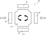
- Fig. 4a and Fig. 4b is the structure of an injection molding device 40 for carrying out the above-mentioned with reference to the figures Fig. 1a to Fig. 1f described procedure is schematically outlined:
- the injection molding device 40 according to Fig. 4a has at least one first injection molding station 41 and at least one stamping station 42.
- the injection molding device 40 has a movably mounted tool carrier 24, which in the embodiment according to Fig. 4a formed by a horizontally arranged turntable, which, as in Fig. 4a As indicated, it is rotatably mounted around the central axis.
- One or more first tool mold halves 21 are arranged on the tool carrier 24, in particular firmly connected thereto, so that the one or more first tool mold halves 21 can be cyclically fed to the injection molding station 41 and the embossing station 42 by rotating the tool carrier 24.
- Fig.5 illustrates an embodiment of the injection molding device 40 according to Fig. 4a , in which two first tool mold halves 21 are mounted on the tool carrier 24.
- Such an arrangement is advantageous compared to the arrangement of only one tool mold half 21 on the tool carrier 24, since the production speed can be doubled as a result. This is because parallel to the embossing of the one or more first film elements 12 on the base body 11 can already be used to cast another base body by the injection molding station 41.
- the injection molding device 40 In addition to the tool carrier 24, the two first tool mold halves 21, the injection molding station 41 and the embossing station 42, it also has an adjusting device 25 for moving the first tool mold halves 21 arranged on the common tool carrier 24 and a process control device 50.
- the injection molding station 41 has at least a second mold half 22, a closing device 411, and an injection unit 412.
- the closing device 411 closes the injection molding tool 20 formed by the first mold half 21 and the second mold half 22 in the injection molding station 41, whereby the first injection molding cavity 212, as can also be seen from Fig. 1a Furthermore, the closing device 411 also opens the injection molding tool 20, as previously explained with reference to Fig. 1c explained.
- the closing device 411 preferably consists of a corresponding guide device and hydraulic and/or pneumatic elements which enable a corresponding translational movement of the second tool mold half 22 to the first tool mold half 21 in the injection molding station 41.
- the injection unit 412 brings, as already described above with reference to Fig. 1b explained, the first plastic material 31 is introduced into the first injection molding cavity 212.
- the injection unit 412 has corresponding elements for melting the first plastic material 31 and injecting it into the injection molding tool 20 with a correspondingly high pressure.
- the embossing station 42 has an embossing unit 421 for embossing the one or more film elements 12 onto at least a partial area of the surface of the base body 11.
- the embossing unit 421 thus carries out the above-mentioned Fig. 1d and Fig. 1e follows the steps outlined above.
- the embossing unit 421 preferably has an embossing tool 422, as well as a film feed device 424 and a film removal device 425, which move the films 426 over the embossing tool 422.
- the embossing unit 421 carries out the processes already described above with reference to the figures Fig. 1d and Fig. 1e explained steps and is designed as already described above.
- the embossing tool 422 is moved in a translational manner in the manner of a lifting press against the embossing holder, which is formed by the first tool mold half 21.
- the embossing tool 422 it is also possible for the embossing tool 422 to be, for example, an embossing roller or a movably mounted embossing head, which applies the one or more first film elements 12 by rolling or a rolling movement on the first surface.
- the adjusting device 25 is preferably designed in the form of a servo motor which, in the case of the tool carrier 24 being designed as a horizontal or vertical turntable, causes a rotary movement of the turntable.
- the process control device 50 consists of one or more microprocessors, peripheral components for controlling the injection molding station 41, the embossing station 42 and the actuating device 25, as well as corresponding software components.
- These software components are designed in such a way that they control the injection molding station 41, the stamping station 42 and the actuating device 25 in such a way that the Fig. 1a to Fig. 1c
- first of all the injection molding station 41 and in particular the closing device 411 and the Spray device 41 is controlled to spray the Fig. 1a to Fig. 1c
- the adjusting device 25 is then controlled to rotate the tool carrier 24 by 180° and thus to feed the first tool mold half 21 with the injection-molded base body 11 to the stamping station 42.
- the stamping unit 421 is then controlled in such a way that it Fig. 1d and Fig. 1e explained method steps and embosses the one or more first film elements 12 onto the base body 11.
- Fig. 4b an embodiment of the injection molding device 40 is shown in which a tool carrier 24 in the form of a sliding table is used instead of a tool carrier 24 in the form of a turntable.
- the injection molding device 40 according to Fig. 4b two tool carriers 24 in the form of a respective sliding table, as well as two first tool mold halves 21 mounted thereon.
- two injection molding stations 41 and two stamping stations 42 are provided, which, as in Fig. 4b are positioned relative to the respective tool carrier 24.
- the injection molding device 40 is otherwise, as described above with reference to Fig.5 described, except that the adjusting device 25 moves the tool carriers 24 alternately to the left and right in a translational manner.
- the injection molding device 40 has four stations, namely the injection molding station 41, the embossing station 42 and a second injection molding station 43 and a demolding station 44.
- the tool carrier 24 is designed here as a vertical and/or horizontal turntable.
- Four first tool mold halves 21 are arranged on the tool carrier 24, each offset by 90° to one another. By rotating the tool carrier 24, these four first tool mold halves 21 can thus be moved cyclically between the stations 41, 42, 43 and 44 of the injection molding device 40.
- the second injection molding station 43 is constructed like the injection molding station 41 according to Fig.3 , except that the second injection molding station 43 applies the second plastic material 32 as a cover layer 13 and the above-mentioned Fig. 2a to Fig. 2b follows the steps outlined above.
- the demoulding station 44 carries out the process described above Fig. 2c
- the demoulding station 44 has, for example, a robot arm which removes the component 10 from the first mould half 21, as can be seen, for example, from Fig. 2c clarified.
- the injection molding device 40 is constructed as already described above with reference to Fig.5 explained, so that in this regard the above explanations apply Fig.5 , Fig. 1a to Fig. 1e , as well as Fig. 2a to Fig. 2c
- the invention is defined in the appended set of claims.
Landscapes
- Engineering & Computer Science (AREA)
- Mechanical Engineering (AREA)
- Manufacturing & Machinery (AREA)
- Injection Moulding Of Plastics Or The Like (AREA)
Applications Claiming Priority (3)
| Application Number | Priority Date | Filing Date | Title |
|---|---|---|---|
| DE102018128194.3A DE102018128194A1 (de) | 2018-11-12 | 2018-11-12 | Verfahren zur Herstellung eines Bauteils sowie Spritzgießvorrichtung |
| DE102019120711 | 2019-07-31 | ||
| PCT/EP2019/080257 WO2020099191A1 (de) | 2018-11-12 | 2019-11-05 | Verfahren zur herstellung eines bauteils sowie spritzgiessvorrichtung |
Publications (2)
| Publication Number | Publication Date |
|---|---|
| EP3880425A1 EP3880425A1 (de) | 2021-09-22 |
| EP3880425B1 true EP3880425B1 (de) | 2024-08-21 |
Family
ID=68470517
Family Applications (1)
| Application Number | Title | Priority Date | Filing Date |
|---|---|---|---|
| EP19798616.9A Active EP3880425B1 (de) | 2018-11-12 | 2019-11-05 | Verfahren zur herstellung eines bauteils sowie spritzgiessvorrichtung |
Country Status (6)
| Country | Link |
|---|---|
| US (1) | US12257823B2 (https=) |
| EP (1) | EP3880425B1 (https=) |
| JP (1) | JP7627215B2 (https=) |
| KR (1) | KR102809949B1 (https=) |
| TW (1) | TWI843761B (https=) |
| WO (1) | WO2020099191A1 (https=) |
Families Citing this family (4)
| Publication number | Priority date | Publication date | Assignee | Title |
|---|---|---|---|---|
| DE102019132787A1 (de) | 2019-12-03 | 2021-06-10 | Leonhard Kurz Stiftung & Co. Kg | Dekorfolie, Verfahren zur Herstellung einer Dekorfolie und Verfahren zur Dekoration eines Zielsubstrats |
| EP3995311A1 (de) * | 2020-11-10 | 2022-05-11 | Illinois Tool Works Inc. | Verfahren und vorrichtung zum bearbeiten und insbesondere veredeln von druckobjekten |
| FR3139495B1 (fr) * | 2022-09-13 | 2025-10-17 | Cie Plastic Omnium Se | Procédé de moulage de panneau de carrosserie |
| KR102650158B1 (ko) | 2023-08-16 | 2024-03-21 | 주식회사 서연이화 | 차량용 스피커 그릴의 성형 방법 |
Family Cites Families (43)
| Publication number | Priority date | Publication date | Assignee | Title |
|---|---|---|---|---|
| JPS61135731A (ja) | 1984-12-07 | 1986-06-23 | Matsushita Electric Ind Co Ltd | プラスチツク成形機 |
| JPS61122819U (https=) | 1985-01-22 | 1986-08-02 | ||
| JPH0667664B2 (ja) * | 1986-05-31 | 1994-08-31 | 尾池工業株式会社 | ホツトスタンピングホイル |
| JPH0818345B2 (ja) * | 1986-11-28 | 1996-02-28 | 橋本フオ−ミング工業株式会社 | 装飾成形品の製造方法 |
| JPS63254016A (ja) * | 1987-04-11 | 1988-10-20 | Dainippon Printing Co Ltd | 絵柄付き食器の製造方法および絵柄付き食器 |
| JPH07324B2 (ja) | 1987-07-15 | 1995-01-11 | 日本プラスト株式会社 | 表皮体を有する合成樹脂製品の製造方法 |
| DE4101106A1 (de) * | 1991-01-16 | 1992-07-23 | Krauss Maffei Ag | Verfahren und vorrichtung zum herstellen laminierter formteile |
| US5443673A (en) * | 1992-06-12 | 1995-08-22 | Donnelly Corporation | Vehicular panel assembly and method for making same |
| JPH06278162A (ja) * | 1993-03-26 | 1994-10-04 | Sakae Riken Kogyo Kk | 装飾用長尺部材およびその製法 |
| JPH0811419A (ja) * | 1994-06-29 | 1996-01-16 | Shinano Polymer Kk | 押釦スイッチ用カバー部材の製造方法 |
| JPH0818345A (ja) | 1994-07-04 | 1996-01-19 | Fujitsu Ltd | クォドラチャ復調回路 |
| US5746962A (en) * | 1995-01-13 | 1998-05-05 | Green Tokai Co., Ltd. | Method of insert molding plastic parts to provide covered edge surfaces |
| JP2628032B2 (ja) | 1995-08-25 | 1997-07-09 | 橋本フォーミング工業株式会社 | 装飾成形品の製造方法 |
| WO1997047454A1 (en) * | 1996-06-10 | 1997-12-18 | Lear Corporation | Method for forming a molded plastic panel |
| US6280823B1 (en) * | 1998-05-22 | 2001-08-28 | Patent Holding Company | Foil-covered plastic part and method of making same |
| SE520827C2 (sv) | 2000-04-05 | 2003-09-02 | Nolato Ab | Aggregat och metod för framställning av bärare av information eller dekoration |
| DE10034839A1 (de) * | 2000-07-18 | 2002-01-31 | Schiffer Fa M & C | Verfahren zur Herstellung von dickwandigen Bürsten, insbesondere Zahnbürsten |
| JP4022819B2 (ja) * | 2002-12-26 | 2007-12-19 | 豊田合成株式会社 | 電波透過カバー |
| DE10252163A1 (de) | 2002-11-09 | 2004-05-27 | Braun Gmbh | Spritzling |
| JP4379874B2 (ja) * | 2004-08-19 | 2009-12-09 | 有限会社ソラーナテクノ | 成形同時印刷システムおよび転写印刷成形品の製造方法 |
| DE102004041833A1 (de) | 2004-08-27 | 2006-03-02 | Leonhard Kurz Gmbh & Co. Kg | Dekorierter Spritzgussartikel, Verfahren zur Herstellung eines dekorierten Spritzgussartikels sowie Transferfolie zur Verwendung in einem derartigen Verfahren |
| NO20055077D0 (no) * | 2005-10-31 | 2005-10-31 | Jordan As | Anordning ved tannborste |
| DE102006016200A1 (de) | 2006-04-06 | 2007-10-11 | Krauss-Maffei Kunststofftechnik Gmbh | Verfahren und Vorrichtung zur Herstellung von mehrkomponentigen Kunststoff-Formteilen |
| KR20080089842A (ko) * | 2007-04-02 | 2008-10-08 | 삼성전자주식회사 | 사출성형장치 및 이를 이용한 사출성형방법 |
| KR20090128059A (ko) * | 2008-06-10 | 2009-12-15 | 삼성전자주식회사 | 사출성형시스템 및 사출성형방법 |
| CN101856858A (zh) | 2009-04-08 | 2010-10-13 | 康准电子科技(昆山)有限公司 | 形成具有微结构的模内装饰模制品的方法及其模制品 |
| CN101873776A (zh) * | 2009-04-27 | 2010-10-27 | 深圳富泰宏精密工业有限公司 | 具有天线功能的电子装置壳体及其制造方法 |
| DE102010019625B4 (de) * | 2009-05-27 | 2017-08-24 | Engel Austria Gmbh | Verfahren zur Herstellung einer Verbund- oder Hybridkonstruktion |
| KR101045996B1 (ko) | 2009-12-21 | 2011-07-01 | (주)피에조테크놀리지 | 압전 리니어 모터 |
| KR20110071745A (ko) | 2009-12-21 | 2011-06-29 | 한국전자통신연구원 | 가상화 시스템상에서의 영상 송수신 환경 설정방법 및 그 장치 |
| DE102010020039A1 (de) | 2010-05-11 | 2011-11-17 | Volkswagen Ag | Verfahren zur Herstellung eines Verkleidungsteils aus Kunststoff sowie Verkleidungsteil aus Kunststoff |
| JP5410384B2 (ja) | 2010-08-09 | 2014-02-05 | 日本写真印刷株式会社 | 転写加飾品の製造方法、転写加飾装置及び転写加飾品 |
| DE102011017040A1 (de) | 2011-04-14 | 2012-10-18 | Awm Mold Tech Ag | Verfahren zum Herstellen eines beschichteten Formteils und Vorrichtungen hierfür |
| DE102011102722B4 (de) | 2011-05-20 | 2017-05-24 | Leonhard Kurz Stiftung & Co. Kg | Verfahren zum In-Mold-Dekorieren |
| US20140037917A1 (en) | 2012-07-31 | 2014-02-06 | Wilsonart Llc | Printed laminate with digital printing and method for manufacture |
| DE102012109315A1 (de) | 2012-10-01 | 2014-04-03 | Leonhard Kurz Stiftung & Co. Kg | Verfahren und Vorrichtung zum Beprägen einer nicht-ebenen Oberfläche eines Körpers mit einer Übertragungslage einer Heißprägefolie |
| GB201219613D0 (en) | 2012-10-31 | 2012-12-12 | Obrist Closures Switzerland | Improvements in or relating to moulding machines |
| CN103354620A (zh) * | 2013-05-31 | 2013-10-16 | 深圳市同洲电子股份有限公司 | 通过移动终端远程控制数字电视终端的方法及其系统 |
| DE102015112374A1 (de) * | 2015-07-29 | 2017-02-02 | International Automotive Components Group Gmbh | Verfahren und Vorrichtung zum Herstellen eines kaschierten Formteils |
| WO2017097444A1 (de) | 2015-12-10 | 2017-06-15 | Votteler Lackfabrik Gmbh & Co. Kg | Verfahren zum beschichten eines substrats |
| BR112018017327A2 (pt) | 2016-06-14 | 2018-12-26 | Saint Gobain | método para produzir uma parte complementar de plástico de veículo |
| DE102017101595B3 (de) * | 2017-01-27 | 2018-05-30 | Leonhard Kurz Stiftung & Co. Kg | Transferfolie, deren Verwendung und Verfahren zur Herstellung einer Transferfolie sowie Verfahren zur Herstellung eines mit einer Transferlage einer Transferfolie dekorierten Spritzgussartikels |
| CN108749282A (zh) | 2018-05-18 | 2018-11-06 | 东莞市金誉印刷有限公司 | 一种轮转式冷烫金印刷机 |
-
2019
- 2019-10-28 TW TW108138860A patent/TWI843761B/zh active
- 2019-11-05 EP EP19798616.9A patent/EP3880425B1/de active Active
- 2019-11-05 KR KR1020217017999A patent/KR102809949B1/ko active Active
- 2019-11-05 US US17/292,948 patent/US12257823B2/en active Active
- 2019-11-05 WO PCT/EP2019/080257 patent/WO2020099191A1/de not_active Ceased
- 2019-11-05 JP JP2021525563A patent/JP7627215B2/ja active Active
Also Published As
| Publication number | Publication date |
|---|---|
| US12257823B2 (en) | 2025-03-25 |
| US20220001662A1 (en) | 2022-01-06 |
| TWI843761B (zh) | 2024-06-01 |
| WO2020099191A1 (de) | 2020-05-22 |
| JP2022507143A (ja) | 2022-01-18 |
| KR102809949B1 (ko) | 2025-05-23 |
| JP7627215B2 (ja) | 2025-02-05 |
| EP3880425A1 (de) | 2021-09-22 |
| TW202106491A (zh) | 2021-02-16 |
| KR20210090685A (ko) | 2021-07-20 |
Similar Documents
| Publication | Publication Date | Title |
|---|---|---|
| DE102018128194A1 (de) | Verfahren zur Herstellung eines Bauteils sowie Spritzgießvorrichtung | |
| EP3880425B1 (de) | Verfahren zur herstellung eines bauteils sowie spritzgiessvorrichtung | |
| EP3083183B1 (de) | Kunststoffformteil und verfahren zu dessen herstellung | |
| EP2923823B1 (de) | Formkörper und verfahren zu dessen herstellung | |
| WO2020182736A2 (de) | Verfahren zur herstellung eines bauteils und vorrichtung zur herstellung eines bauteils | |
| EP3468798B1 (de) | Verfahren zur herstellung eines kunststoff-fahrzeuganbauteils, vorrichtung, produkt und verwendung | |
| DE10029678A1 (de) | Gehäusekasten und Verfahren zu dessen Herstellung | |
| EP1705152A2 (de) | Verfahren und Vorrichtung, um Mikro- oder nanostrukturierte Bauteile gebrauchsbeständig zu gestalten | |
| DE102015201261A1 (de) | Innenausstattungsteil für fahrzeuge sowie ein verfahren zum herstellen eines solchen innenausstattungsteils | |
| EP4041553A1 (de) | Beschichtungsvorrichtung und verfahren mit prägestation und druckstation | |
| EP4384367A1 (de) | Spritzgussfertigung eines bauteils | |
| EP3127679B1 (de) | Vorrichtung und verfahren zur herstellung eines kunststoff-spritzgussteils mit dekoreinlage | |
| EP2160276B1 (de) | Verfahren zum herstellen von farbigen, dreidimensional strukturierten bauteilen mit freiformflächen | |
| WO2009077400A2 (de) | Verfahren zum herstellen von formteilen | |
| EP2673126B1 (de) | Formwerkzeug zum hinterspritzen einer kunststofffolie mit einer kunststoffschmelze | |
| DE4339909A1 (de) | Geprägtes Gußprodukt und Verfahren zu dessen Herstellung | |
| DE102017220302A1 (de) | Vorrichtung und verfahren zur herstellung integraler embleme | |
| DE102016001805A1 (de) | Bedruckter Kunststoffgegenstand sowie Verfahren und Vorrichtung zur Herstellung desselben | |
| EP0995570A1 (de) | Verfahren zum Erzeugen eines farbig dekorierten Spritzgussteiles |
Legal Events
| Date | Code | Title | Description |
|---|---|---|---|
| STAA | Information on the status of an ep patent application or granted ep patent |
Free format text: STATUS: UNKNOWN |
|
| STAA | Information on the status of an ep patent application or granted ep patent |
Free format text: STATUS: THE INTERNATIONAL PUBLICATION HAS BEEN MADE |
|
| PUAI | Public reference made under article 153(3) epc to a published international application that has entered the european phase |
Free format text: ORIGINAL CODE: 0009012 |
|
| STAA | Information on the status of an ep patent application or granted ep patent |
Free format text: STATUS: REQUEST FOR EXAMINATION WAS MADE |
|
| 17P | Request for examination filed |
Effective date: 20210528 |
|
| AK | Designated contracting states |
Kind code of ref document: A1 Designated state(s): AL AT BE BG CH CY CZ DE DK EE ES FI FR GB GR HR HU IE IS IT LI LT LU LV MC MK MT NL NO PL PT RO RS SE SI SK SM TR |
|
| DAV | Request for validation of the european patent (deleted) | ||
| DAX | Request for extension of the european patent (deleted) | ||
| STAA | Information on the status of an ep patent application or granted ep patent |
Free format text: STATUS: EXAMINATION IS IN PROGRESS |
|
| 17Q | First examination report despatched |
Effective date: 20221027 |
|
| GRAP | Despatch of communication of intention to grant a patent |
Free format text: ORIGINAL CODE: EPIDOSNIGR1 |
|
| STAA | Information on the status of an ep patent application or granted ep patent |
Free format text: STATUS: GRANT OF PATENT IS INTENDED |
|
| INTG | Intention to grant announced |
Effective date: 20240610 |
|
| GRAS | Grant fee paid |
Free format text: ORIGINAL CODE: EPIDOSNIGR3 |
|
| GRAA | (expected) grant |
Free format text: ORIGINAL CODE: 0009210 |
|
| STAA | Information on the status of an ep patent application or granted ep patent |
Free format text: STATUS: THE PATENT HAS BEEN GRANTED |
|
| AK | Designated contracting states |
Kind code of ref document: B1 Designated state(s): AL AT BE BG CH CY CZ DE DK EE ES FI FR GB GR HR HU IE IS IT LI LT LU LV MC MK MT NL NO PL PT RO RS SE SI SK SM TR |
|
| REG | Reference to a national code |
Ref country code: GB Ref legal event code: FG4D Free format text: NOT ENGLISH |
|
| REG | Reference to a national code |
Ref country code: CH Ref legal event code: EP |
|
| REG | Reference to a national code |
Ref country code: DE Ref legal event code: R096 Ref document number: 502019011946 Country of ref document: DE |
|
| REG | Reference to a national code |
Ref country code: IE Ref legal event code: FG4D Free format text: LANGUAGE OF EP DOCUMENT: GERMAN |
|
| REG | Reference to a national code |
Ref country code: LT Ref legal event code: MG9D |
|
| REG | Reference to a national code |
Ref country code: NL Ref legal event code: MP Effective date: 20240821 |
|
| PG25 | Lapsed in a contracting state [announced via postgrant information from national office to epo] |
Ref country code: NO Free format text: LAPSE BECAUSE OF FAILURE TO SUBMIT A TRANSLATION OF THE DESCRIPTION OR TO PAY THE FEE WITHIN THE PRESCRIBED TIME-LIMIT Effective date: 20241121 |
|
| PG25 | Lapsed in a contracting state [announced via postgrant information from national office to epo] |
Ref country code: NL Free format text: LAPSE BECAUSE OF FAILURE TO SUBMIT A TRANSLATION OF THE DESCRIPTION OR TO PAY THE FEE WITHIN THE PRESCRIBED TIME-LIMIT Effective date: 20240821 Ref country code: GR Free format text: LAPSE BECAUSE OF FAILURE TO SUBMIT A TRANSLATION OF THE DESCRIPTION OR TO PAY THE FEE WITHIN THE PRESCRIBED TIME-LIMIT Effective date: 20241122 Ref country code: FI Free format text: LAPSE BECAUSE OF FAILURE TO SUBMIT A TRANSLATION OF THE DESCRIPTION OR TO PAY THE FEE WITHIN THE PRESCRIBED TIME-LIMIT Effective date: 20240821 Ref country code: PT Free format text: LAPSE BECAUSE OF FAILURE TO SUBMIT A TRANSLATION OF THE DESCRIPTION OR TO PAY THE FEE WITHIN THE PRESCRIBED TIME-LIMIT Effective date: 20241223 Ref country code: PL Free format text: LAPSE BECAUSE OF FAILURE TO SUBMIT A TRANSLATION OF THE DESCRIPTION OR TO PAY THE FEE WITHIN THE PRESCRIBED TIME-LIMIT Effective date: 20240821 |
|
| PG25 | Lapsed in a contracting state [announced via postgrant information from national office to epo] |
Ref country code: BG Free format text: LAPSE BECAUSE OF FAILURE TO SUBMIT A TRANSLATION OF THE DESCRIPTION OR TO PAY THE FEE WITHIN THE PRESCRIBED TIME-LIMIT Effective date: 20240821 |
|
| PG25 | Lapsed in a contracting state [announced via postgrant information from national office to epo] |
Ref country code: LV Free format text: LAPSE BECAUSE OF FAILURE TO SUBMIT A TRANSLATION OF THE DESCRIPTION OR TO PAY THE FEE WITHIN THE PRESCRIBED TIME-LIMIT Effective date: 20240821 |
|
| PG25 | Lapsed in a contracting state [announced via postgrant information from national office to epo] |
Ref country code: IS Free format text: LAPSE BECAUSE OF FAILURE TO SUBMIT A TRANSLATION OF THE DESCRIPTION OR TO PAY THE FEE WITHIN THE PRESCRIBED TIME-LIMIT Effective date: 20241221 |
|
| PG25 | Lapsed in a contracting state [announced via postgrant information from national office to epo] |
Ref country code: HR Free format text: LAPSE BECAUSE OF FAILURE TO SUBMIT A TRANSLATION OF THE DESCRIPTION OR TO PAY THE FEE WITHIN THE PRESCRIBED TIME-LIMIT Effective date: 20240821 |
|
| PG25 | Lapsed in a contracting state [announced via postgrant information from national office to epo] |
Ref country code: RS Free format text: LAPSE BECAUSE OF FAILURE TO SUBMIT A TRANSLATION OF THE DESCRIPTION OR TO PAY THE FEE WITHIN THE PRESCRIBED TIME-LIMIT Effective date: 20241121 Ref country code: ES Free format text: LAPSE BECAUSE OF FAILURE TO SUBMIT A TRANSLATION OF THE DESCRIPTION OR TO PAY THE FEE WITHIN THE PRESCRIBED TIME-LIMIT Effective date: 20240821 |
|
| PG25 | Lapsed in a contracting state [announced via postgrant information from national office to epo] |
Ref country code: RS Free format text: LAPSE BECAUSE OF FAILURE TO SUBMIT A TRANSLATION OF THE DESCRIPTION OR TO PAY THE FEE WITHIN THE PRESCRIBED TIME-LIMIT Effective date: 20241121 Ref country code: PT Free format text: LAPSE BECAUSE OF FAILURE TO SUBMIT A TRANSLATION OF THE DESCRIPTION OR TO PAY THE FEE WITHIN THE PRESCRIBED TIME-LIMIT Effective date: 20241223 Ref country code: PL Free format text: LAPSE BECAUSE OF FAILURE TO SUBMIT A TRANSLATION OF THE DESCRIPTION OR TO PAY THE FEE WITHIN THE PRESCRIBED TIME-LIMIT Effective date: 20240821 Ref country code: NO Free format text: LAPSE BECAUSE OF FAILURE TO SUBMIT A TRANSLATION OF THE DESCRIPTION OR TO PAY THE FEE WITHIN THE PRESCRIBED TIME-LIMIT Effective date: 20241121 Ref country code: NL Free format text: LAPSE BECAUSE OF FAILURE TO SUBMIT A TRANSLATION OF THE DESCRIPTION OR TO PAY THE FEE WITHIN THE PRESCRIBED TIME-LIMIT Effective date: 20240821 Ref country code: LV Free format text: LAPSE BECAUSE OF FAILURE TO SUBMIT A TRANSLATION OF THE DESCRIPTION OR TO PAY THE FEE WITHIN THE PRESCRIBED TIME-LIMIT Effective date: 20240821 Ref country code: IS Free format text: LAPSE BECAUSE OF FAILURE TO SUBMIT A TRANSLATION OF THE DESCRIPTION OR TO PAY THE FEE WITHIN THE PRESCRIBED TIME-LIMIT Effective date: 20241221 Ref country code: HR Free format text: LAPSE BECAUSE OF FAILURE TO SUBMIT A TRANSLATION OF THE DESCRIPTION OR TO PAY THE FEE WITHIN THE PRESCRIBED TIME-LIMIT Effective date: 20240821 Ref country code: GR Free format text: LAPSE BECAUSE OF FAILURE TO SUBMIT A TRANSLATION OF THE DESCRIPTION OR TO PAY THE FEE WITHIN THE PRESCRIBED TIME-LIMIT Effective date: 20241122 Ref country code: FI Free format text: LAPSE BECAUSE OF FAILURE TO SUBMIT A TRANSLATION OF THE DESCRIPTION OR TO PAY THE FEE WITHIN THE PRESCRIBED TIME-LIMIT Effective date: 20240821 Ref country code: ES Free format text: LAPSE BECAUSE OF FAILURE TO SUBMIT A TRANSLATION OF THE DESCRIPTION OR TO PAY THE FEE WITHIN THE PRESCRIBED TIME-LIMIT Effective date: 20240821 Ref country code: BG Free format text: LAPSE BECAUSE OF FAILURE TO SUBMIT A TRANSLATION OF THE DESCRIPTION OR TO PAY THE FEE WITHIN THE PRESCRIBED TIME-LIMIT Effective date: 20240821 |
|
| PG25 | Lapsed in a contracting state [announced via postgrant information from national office to epo] |
Ref country code: RO Free format text: LAPSE BECAUSE OF FAILURE TO SUBMIT A TRANSLATION OF THE DESCRIPTION OR TO PAY THE FEE WITHIN THE PRESCRIBED TIME-LIMIT Effective date: 20240821 Ref country code: DK Free format text: LAPSE BECAUSE OF FAILURE TO SUBMIT A TRANSLATION OF THE DESCRIPTION OR TO PAY THE FEE WITHIN THE PRESCRIBED TIME-LIMIT Effective date: 20240821 Ref country code: SM Free format text: LAPSE BECAUSE OF FAILURE TO SUBMIT A TRANSLATION OF THE DESCRIPTION OR TO PAY THE FEE WITHIN THE PRESCRIBED TIME-LIMIT Effective date: 20240821 |
|
| PG25 | Lapsed in a contracting state [announced via postgrant information from national office to epo] |
Ref country code: EE Free format text: LAPSE BECAUSE OF FAILURE TO SUBMIT A TRANSLATION OF THE DESCRIPTION OR TO PAY THE FEE WITHIN THE PRESCRIBED TIME-LIMIT Effective date: 20240821 |
|
| PG25 | Lapsed in a contracting state [announced via postgrant information from national office to epo] |
Ref country code: CZ Free format text: LAPSE BECAUSE OF FAILURE TO SUBMIT A TRANSLATION OF THE DESCRIPTION OR TO PAY THE FEE WITHIN THE PRESCRIBED TIME-LIMIT Effective date: 20240821 |
|
| PG25 | Lapsed in a contracting state [announced via postgrant information from national office to epo] |
Ref country code: SK Free format text: LAPSE BECAUSE OF FAILURE TO SUBMIT A TRANSLATION OF THE DESCRIPTION OR TO PAY THE FEE WITHIN THE PRESCRIBED TIME-LIMIT Effective date: 20240821 Ref country code: IT Free format text: LAPSE BECAUSE OF FAILURE TO SUBMIT A TRANSLATION OF THE DESCRIPTION OR TO PAY THE FEE WITHIN THE PRESCRIBED TIME-LIMIT Effective date: 20240821 |
|
| REG | Reference to a national code |
Ref country code: DE Ref legal event code: R097 Ref document number: 502019011946 Country of ref document: DE |
|
| PLBE | No opposition filed within time limit |
Free format text: ORIGINAL CODE: 0009261 |
|
| STAA | Information on the status of an ep patent application or granted ep patent |
Free format text: STATUS: NO OPPOSITION FILED WITHIN TIME LIMIT |
|
| REG | Reference to a national code |
Ref country code: CH Ref legal event code: PL |
|
| PG25 | Lapsed in a contracting state [announced via postgrant information from national office to epo] |
Ref country code: MC Free format text: LAPSE BECAUSE OF FAILURE TO SUBMIT A TRANSLATION OF THE DESCRIPTION OR TO PAY THE FEE WITHIN THE PRESCRIBED TIME-LIMIT Effective date: 20240821 |
|
| PG25 | Lapsed in a contracting state [announced via postgrant information from national office to epo] |
Ref country code: LU Free format text: LAPSE BECAUSE OF NON-PAYMENT OF DUE FEES Effective date: 20241105 |
|
| REG | Reference to a national code |
Ref country code: CH Ref legal event code: PL |
|
| GBPC | Gb: european patent ceased through non-payment of renewal fee |
Effective date: 20241121 |
|
| PG25 | Lapsed in a contracting state [announced via postgrant information from national office to epo] |
Ref country code: CH Free format text: LAPSE BECAUSE OF NON-PAYMENT OF DUE FEES Effective date: 20241130 |
|
| 26N | No opposition filed |
Effective date: 20250522 |
|
| REG | Reference to a national code |
Ref country code: BE Ref legal event code: MM Effective date: 20241130 |
|
| PG25 | Lapsed in a contracting state [announced via postgrant information from national office to epo] |
Ref country code: SE Free format text: LAPSE BECAUSE OF FAILURE TO SUBMIT A TRANSLATION OF THE DESCRIPTION OR TO PAY THE FEE WITHIN THE PRESCRIBED TIME-LIMIT Effective date: 20240821 |
|
| PG25 | Lapsed in a contracting state [announced via postgrant information from national office to epo] |
Ref country code: BE Free format text: LAPSE BECAUSE OF NON-PAYMENT OF DUE FEES Effective date: 20241130 Ref country code: GB Free format text: LAPSE BECAUSE OF NON-PAYMENT OF DUE FEES Effective date: 20241121 |
|
| PG25 | Lapsed in a contracting state [announced via postgrant information from national office to epo] |
Ref country code: IE Free format text: LAPSE BECAUSE OF NON-PAYMENT OF DUE FEES Effective date: 20241105 |
|
| PGFP | Annual fee paid to national office [announced via postgrant information from national office to epo] |
Ref country code: DE Payment date: 20251121 Year of fee payment: 7 |
|
| PG25 | Lapsed in a contracting state [announced via postgrant information from national office to epo] |
Ref country code: AT Free format text: LAPSE BECAUSE OF NON-PAYMENT OF DUE FEES Effective date: 20241105 |
|
| PGFP | Annual fee paid to national office [announced via postgrant information from national office to epo] |
Ref country code: FR Payment date: 20251114 Year of fee payment: 7 |
|
| REG | Reference to a national code |
Ref country code: AT Ref legal event code: MM01 Ref document number: 1715122 Country of ref document: AT Kind code of ref document: T Effective date: 20241105 |
|
| PG25 | Lapsed in a contracting state [announced via postgrant information from national office to epo] |
Ref country code: HU Free format text: LAPSE BECAUSE OF FAILURE TO SUBMIT A TRANSLATION OF THE DESCRIPTION OR TO PAY THE FEE WITHIN THE PRESCRIBED TIME-LIMIT; INVALID AB INITIO Effective date: 20191105 |
|
| PG25 | Lapsed in a contracting state [announced via postgrant information from national office to epo] |
Ref country code: CY Free format text: LAPSE BECAUSE OF FAILURE TO SUBMIT A TRANSLATION OF THE DESCRIPTION OR TO PAY THE FEE WITHIN THE PRESCRIBED TIME-LIMIT; INVALID AB INITIO Effective date: 20191105 |