EP3876515B1 - Abbildungsvorrichtung, steuerungsverfahren und programm - Google Patents
Abbildungsvorrichtung, steuerungsverfahren und programm Download PDFInfo
- Publication number
- EP3876515B1 EP3876515B1 EP19879266.5A EP19879266A EP3876515B1 EP 3876515 B1 EP3876515 B1 EP 3876515B1 EP 19879266 A EP19879266 A EP 19879266A EP 3876515 B1 EP3876515 B1 EP 3876515B1
- Authority
- EP
- European Patent Office
- Prior art keywords
- image
- vehicle
- reading
- controller
- information
- Prior art date
- Legal status (The legal status is an assumption and is not a legal conclusion. Google has not performed a legal analysis and makes no representation as to the accuracy of the status listed.)
- Active
Links
Images


Classifications
-
- H—ELECTRICITY
- H04—ELECTRIC COMMUNICATION TECHNIQUE
- H04N—PICTORIAL COMMUNICATION, e.g. TELEVISION
- H04N23/00—Cameras or camera modules comprising electronic image sensors; Control thereof
- H04N23/50—Constructional details
- H04N23/54—Mounting of pick-up tubes, electronic image sensors, deviation or focusing coils
-
- B—PERFORMING OPERATIONS; TRANSPORTING
- B60—VEHICLES IN GENERAL
- B60R—VEHICLES, VEHICLE FITTINGS, OR VEHICLE PARTS, NOT OTHERWISE PROVIDED FOR
- B60R1/00—Optical viewing arrangements; Real-time viewing arrangements for drivers or passengers using optical image capturing systems, e.g. cameras or video systems specially adapted for use in or on vehicles
- B60R1/20—Real-time viewing arrangements for drivers or passengers using optical image capturing systems, e.g. cameras or video systems specially adapted for use in or on vehicles
- B60R1/22—Real-time viewing arrangements for drivers or passengers using optical image capturing systems, e.g. cameras or video systems specially adapted for use in or on vehicles for viewing an area outside the vehicle, e.g. the exterior of the vehicle
- B60R1/23—Real-time viewing arrangements for drivers or passengers using optical image capturing systems, e.g. cameras or video systems specially adapted for use in or on vehicles for viewing an area outside the vehicle, e.g. the exterior of the vehicle with a predetermined field of view
- B60R1/26—Real-time viewing arrangements for drivers or passengers using optical image capturing systems, e.g. cameras or video systems specially adapted for use in or on vehicles for viewing an area outside the vehicle, e.g. the exterior of the vehicle with a predetermined field of view to the rear of the vehicle
-
- G—PHYSICS
- G03—PHOTOGRAPHY; CINEMATOGRAPHY; ANALOGOUS TECHNIQUES USING WAVES OTHER THAN OPTICAL WAVES; ELECTROGRAPHY; HOLOGRAPHY
- G03B—APPARATUS OR ARRANGEMENTS FOR TAKING PHOTOGRAPHS OR FOR PROJECTING OR VIEWING THEM; APPARATUS OR ARRANGEMENTS EMPLOYING ANALOGOUS TECHNIQUES USING WAVES OTHER THAN OPTICAL WAVES; ACCESSORIES THEREFOR
- G03B37/00—Panoramic or wide-screen photography; Photographing extended surfaces, e.g. for surveying; Photographing internal surfaces, e.g. of pipe
-
- G—PHYSICS
- G06—COMPUTING OR CALCULATING; COUNTING
- G06T—IMAGE DATA PROCESSING OR GENERATION, IN GENERAL
- G06T3/00—Geometric image transformations in the plane of the image
- G06T3/60—Rotation of whole images or parts thereof
-
- G—PHYSICS
- G06—COMPUTING OR CALCULATING; COUNTING
- G06T—IMAGE DATA PROCESSING OR GENERATION, IN GENERAL
- G06T7/00—Image analysis
- G06T7/60—Analysis of geometric attributes
-
- H—ELECTRICITY
- H04—ELECTRIC COMMUNICATION TECHNIQUE
- H04N—PICTORIAL COMMUNICATION, e.g. TELEVISION
- H04N23/00—Cameras or camera modules comprising electronic image sensors; Control thereof
- H04N23/60—Control of cameras or camera modules
-
- H—ELECTRICITY
- H04—ELECTRIC COMMUNICATION TECHNIQUE
- H04N—PICTORIAL COMMUNICATION, e.g. TELEVISION
- H04N23/00—Cameras or camera modules comprising electronic image sensors; Control thereof
- H04N23/60—Control of cameras or camera modules
- H04N23/69—Control of means for changing angle of the field of view, e.g. optical zoom objectives or electronic zooming
-
- H—ELECTRICITY
- H04—ELECTRIC COMMUNICATION TECHNIQUE
- H04N—PICTORIAL COMMUNICATION, e.g. TELEVISION
- H04N23/00—Cameras or camera modules comprising electronic image sensors; Control thereof
- H04N23/60—Control of cameras or camera modules
- H04N23/698—Control of cameras or camera modules for achieving an enlarged field of view, e.g. panoramic image capture
-
- H—ELECTRICITY
- H04—ELECTRIC COMMUNICATION TECHNIQUE
- H04N—PICTORIAL COMMUNICATION, e.g. TELEVISION
- H04N23/00—Cameras or camera modules comprising electronic image sensors; Control thereof
- H04N23/80—Camera processing pipelines; Components thereof
-
- H—ELECTRICITY
- H04—ELECTRIC COMMUNICATION TECHNIQUE
- H04N—PICTORIAL COMMUNICATION, e.g. TELEVISION
- H04N25/00—Circuitry of solid-state image sensors [SSIS]; Control thereof
- H04N25/40—Extracting pixel data from image sensors by controlling scanning circuits, e.g. by modifying the number of pixels sampled or to be sampled
- H04N25/44—Extracting pixel data from image sensors by controlling scanning circuits, e.g. by modifying the number of pixels sampled or to be sampled by partially reading an SSIS array
- H04N25/441—Extracting pixel data from image sensors by controlling scanning circuits, e.g. by modifying the number of pixels sampled or to be sampled by partially reading an SSIS array by reading contiguous pixels from selected rows or columns of the array, e.g. interlaced scanning
-
- H—ELECTRICITY
- H04—ELECTRIC COMMUNICATION TECHNIQUE
- H04N—PICTORIAL COMMUNICATION, e.g. TELEVISION
- H04N25/00—Circuitry of solid-state image sensors [SSIS]; Control thereof
- H04N25/40—Extracting pixel data from image sensors by controlling scanning circuits, e.g. by modifying the number of pixels sampled or to be sampled
- H04N25/46—Extracting pixel data from image sensors by controlling scanning circuits, e.g. by modifying the number of pixels sampled or to be sampled by combining or binning pixels
-
- H—ELECTRICITY
- H04—ELECTRIC COMMUNICATION TECHNIQUE
- H04N—PICTORIAL COMMUNICATION, e.g. TELEVISION
- H04N25/00—Circuitry of solid-state image sensors [SSIS]; Control thereof
- H04N25/70—SSIS architectures; Circuits associated therewith
- H04N25/71—Charge-coupled device [CCD] sensors; Charge-transfer registers specially adapted for CCD sensors
- H04N25/75—Circuitry for providing, modifying or processing image signals from the pixel array
-
- H—ELECTRICITY
- H04—ELECTRIC COMMUNICATION TECHNIQUE
- H04N—PICTORIAL COMMUNICATION, e.g. TELEVISION
- H04N25/00—Circuitry of solid-state image sensors [SSIS]; Control thereof
- H04N25/70—SSIS architectures; Circuits associated therewith
- H04N25/79—Arrangements of circuitry being divided between different or multiple substrates, chips or circuit boards, e.g. stacked image sensors
-
- H—ELECTRICITY
- H04—ELECTRIC COMMUNICATION TECHNIQUE
- H04N—PICTORIAL COMMUNICATION, e.g. TELEVISION
- H04N5/00—Details of television systems
- H04N5/222—Studio circuitry; Studio devices; Studio equipment
- H04N5/262—Studio circuits, e.g. for mixing, switching-over, change of character of image, other special effects ; Cameras specially adapted for the electronic generation of special effects
- H04N5/2628—Alteration of picture size, shape, position or orientation, e.g. zooming, rotation, rolling, perspective, translation
-
- H—ELECTRICITY
- H04—ELECTRIC COMMUNICATION TECHNIQUE
- H04N—PICTORIAL COMMUNICATION, e.g. TELEVISION
- H04N7/00—Television systems
- H04N7/18—Closed-circuit television [CCTV] systems, i.e. systems in which the video signal is not broadcast
-
- H—ELECTRICITY
- H04—ELECTRIC COMMUNICATION TECHNIQUE
- H04N—PICTORIAL COMMUNICATION, e.g. TELEVISION
- H04N7/00—Television systems
- H04N7/18—Closed-circuit television [CCTV] systems, i.e. systems in which the video signal is not broadcast
- H04N7/183—Closed-circuit television [CCTV] systems, i.e. systems in which the video signal is not broadcast for receiving images from a single remote source
-
- B—PERFORMING OPERATIONS; TRANSPORTING
- B60—VEHICLES IN GENERAL
- B60R—VEHICLES, VEHICLE FITTINGS, OR VEHICLE PARTS, NOT OTHERWISE PROVIDED FOR
- B60R2300/00—Details of viewing arrangements using cameras and displays, specially adapted for use in a vehicle
- B60R2300/30—Details of viewing arrangements using cameras and displays, specially adapted for use in a vehicle characterised by the type of image processing
- B60R2300/302—Details of viewing arrangements using cameras and displays, specially adapted for use in a vehicle characterised by the type of image processing combining image information with GPS information or vehicle data, e.g. vehicle speed, gyro, steering angle data
Definitions
- the present technology relates to an image-capturing apparatus, a control method, and a program.
- the present technology relates to, for example, an image-capturing apparatus, a control method, and a program that make it possible to easily provide an image suitable for the operation of a vehicle.
- a viewing system in which a camera that is an image-capturing apparatus is installed in the rear of a vehicle such as an automobile and an image of a region behind the vehicle that is captured using the camera is displayed, is proposed.
- Examples of the image of a region behind a vehicle that is provided by the viewing system include an image of a region situated further rearward than a region just behind the rear of the vehicle, and an image of the region just behind the rear of the vehicle.
- the image of a region situated further rearward than a region just behind the rear of a vehicle is, for example, an image that corresponds to an image seen in a Class I mirror, which is a so-called interior rearview mirror, and is hereinafter also referred to as a back mirror (BM) image.
- BM back mirror
- the image of a region just behind the rear of a vehicle is an image of the rear of the vehicle and a region just behind the rear of the vehicle, and is hereinafter also referred to as a rearview (RV) image.
- RV rearview
- a vehicle is inclined when the vehicle starts going up or down a hill or is traveling on an uneven road surface. Further, the vehicle may also be inclined according to, for example, an object loaded on the vehicle or a state of an occupant of the vehicle.
- the BM image suitable for the operation of the vehicle will not be displayed in some cases if the ratio of the sky, a road, and the like in the BM image is changed due to the inclination of the vehicle.
- a BM image is displayed that enables a driver to sufficiently recognize, for example, another vehicle that is getting close to the vehicle from behind, or an obstacle behind the vehicle.
- the BM image may include less information necessary for the driver to recognize the other vehicle or the obstacle.
- a technology has been proposed that stores a captured image in a storage and cuts a necessary image out of the captured image when the vehicle is traveling up or down a hill, the captured image being captured using a camera, the storage being situated posterior to the camera (for example, refer to Patent Literature 1).
- Patent Literature 1 Japanese Patent No. 6245274
- WO 2017/187811 A1 discloses a shooting control apparatus and a shooting control method for controlling operations of a shooting part mounted on a mobile object such as automobile, as well as a shooting apparatus mounted on a mobile object for use.
- a central region is configured of fine pixels, thereby realizing high-resolution shooting.
- peripheral regions are configured of large-size pixels or are at a high sensitivity by pixel addition, thereby reducing blur or focal plane distortion by shortening the exposure time when fast driving or shooting a moving object. Further, while travelling during the nighttime or in a dark place, the peripheral regions not irradiated by the head lamps can be shot in a long exposure time and at a sufficient sensitivity.
- US 2008/0253616 A1 discloses an image pickup system having a structure capable of imaging a subject at a low power consumption and a low cost even when the subject may be dark.
- the image pickup system comprises an image pickup device, a peak position detecting section, a partial image acquiring section, and a partial image operating section.
- the image pickup device outputs image data that represents the two-dimensional intensity distribution of light incident on a photodetecting section, and outputs light intensity profile data that represents a one-dimensional intensity distribution of the incident light in each of the first and second directions in the photodetecting section.
- the partial image acquiring section acquires a partial image from an entire image that can be imaged by the image pickup device so that the light intensity peak position detected by the peak position detecting section is made a specific position for the partial image in the entire image.
- the partial image operating section integrates the acquired partial image.
- US 2016/0263997 A1 discloses a display control apparatus including a memory and a controller.
- the memory stores a source picture taken by a rear view camera attached to a vehicle.
- the controller detects a road gradient and calculates a first point on a road that is located at a predetermined distance from the vehicle, based on the detected road gradient.
- the controller then crops out a partial area of the source picture such that the partial area includes a second point on a straight line between the rear view camera and the first point on the road, and displays a picture of the partial area.
- JP2018012439 A discloses a rear view assistance device for capturing a scene behind a vehicle, having an image generation unit cutting out an image of specific range from a captured image according to a leftward/rightward inclination angle.
- the present technology has been made in view of the circumstances described above, and is intended to make it possible to easily provide an image suitable for the operation of a vehicle.
- reading of an image from an image sensor that captures the image is controlled on the basis of vehicle information acquired by a vehicle, the image being displayed on a display section of the vehicle.
- the image-capturing apparatus may be an independent apparatus or an internal block included in a single apparatus.
- the program can be provided by being transmitted through a transmission medium or by being stored in a recording medium.
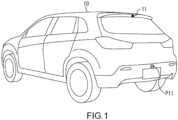
- Fig. 1 is a perspective view illustrating an example of a configuration of an appearance of a vehicle 10 that includes a viewing system to which the present technology is applied.
- a camera unit 11 that is an image-capturing apparatus used to capture an image of a region behind the (four-wheeled) vehicle 10 is installed in the rear of the vehicle 10.
- the camera unit 11 is installed above a rear window of the vehicle 10.
- the camera unit 11 is a wide-angle camera unit (for example, the angle of view is 120 degrees or more) such that it is possible to capture an image in which both a range corresponding to a BM image and a range corresponding to an RV image appear. Further, the camera unit 11 is a high-resolution camera unit (for example, a resolution of 4K or more) such that a distant subject is apparent in the BM image. Thus, the camera unit 11 is capable of capturing a wide-angle, high-resolution image.
- a BM image and an RV image are extracted from an image captured by the camera unit 11 (hereinafter also referred to as a captured image). This will be described later.
- the camera unit 11 is installed in a state in which the orientation of the optical axis has been adjusted, such that the BM image includes an image of a state of a region situated further rearward than a region just behind the rear of the vehicle 10, and such that the RV image includes an image of states of the rear of the vehicle 10 and the region just behind the rear of the vehicle 10, the state of the region situated further rearward than the region just behind the rear of the vehicle 10 being a state that can be observed using an interior rearview mirror (a Class I mirror in Regulation No. 46 defined by the United Nations Economic Commission for Europe ⁇ UNECE>) when the interior rearview mirror is installed in the vehicle 10.
- an interior rearview mirror a Class I mirror in Regulation No. 46 defined by the United Nations Economic Commission for Europe ⁇ UNECE>
- the BM image is an image of a state of a region situated further rearward than a region just behind the rear of the vehicle 10, the state being a state that can be observed using an interior rearview mirror when the interior rearview mirror is installed in the vehicle 10.
- the RV image is an image of states of the rear of the vehicle 10 and the region just behind the rear of the vehicle 10. The RV image is particularly useful when the vehicle 10 is traveling backward, since a region just behind the rear of the vehicle 10 that is a blind spot of the interior rearview mirror appears in the RV image. Further, the RV image can be used to generate an overhead image obtained when the vehicle 10 is viewed from above.
- the camera unit 11 is not limited to being installed above the rear window of the vehicle 10 as long as it is possible to capture a captured image from which the BM image and the RV image described above can be extracted.
- the camera unit 11 may be installed at, for example, a position P11 above a license plate situated in the rear of the vehicle 10.
- Fig. 2 is a perspective view illustrating an example of a configuration of the interior of the vehicle 10 of Fig. 1 .
- a BM display section 21 that displays thereon a BM image is provided at a position, in the vehicle 10, at which the interior rearview mirror is installed.
- the BM display section 21 is a display section that is an alternative to the interior rearview mirror.
- An RV display section 22 that displays thereon an RV image is provided at a center position of a dashboard in the vehicle 10.
- an in-vehicle camera 23 used to capture an image of a driver is provided on the side of a driver's seat of the dashboard in the vehicle 10. An image of the driver is captured to be output by the in-vehicle camera 23. In the vehicle 10, positions of the line of sight and the head of the driver are detected from the image of the driver.
- the in-vehicle camera 23 used to capture an image of the driver may be provided at any position other than a position on the dashboard, such as a position P21 above the BM display section 21.
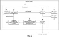
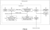
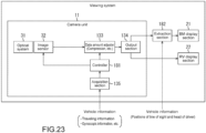
- Fig. 3 is a block diagram illustrating a first example of a configuration of the viewing system included in the vehicle 10.
- the viewing system includes the camera unit 11, the BM display section 21, and the RV display section 22 described with reference to Figs. 1 and 2 .
- the camera unit 11 includes an optical system 31, an image sensor 32, an output section 33, an acquisition section 41, a detector 42, and a controller 43.
- the optical system 31 includes optical components such as a condenser and a diaphragm, and collects light entering the optical system 31 onto the image sensor 32.
- the image sensor 32 receives light from the optical system 31 and performs photoelectric conversion to capture a captured image that includes images that are a BM image and an RV image. Then, in accordance with control performed by the controller 43, the image sensor 32 reads (the images that are) the BM image and the RV image from the captured image to output the read images.
- the image read from the captured image and output by the image sensor 32 is also referred to as a read image.
- the read image output by the image sensor 32 is supplied to the output section 33.
- the output section 33 is an output interface (IF) that transmits, to the outside of the camera unit 11, the BM image and the RV image that are read images from the image sensor 32.
- the output section 33 transmits the BM image to the BM display section 21, and transmits the RV image to the RV display section 22.
- the BM image from the output section 33 is displayed on the BM display section 21 in accordance with the specification of the BM display section 21, and the RV image from the output section 33 is displayed on the RV display section 22 in accordance with the specification of the RV display section 22.
- the output section 33 is capable of performing a format conversion and other image processing on the BM image and the RV image as necessary.
- the acquisition section 41 acquires (receives), from the vehicle 10 and through a network (a vehicle information network) established in the vehicle 10, vehicle information acquired by the vehicle 10, and supplies the acquired vehicle information to the detector 42.
- a network a vehicle information network
- examples of the vehicle information include any information that can be acquired by the vehicle 10, such as gyroscopic information obtained from a gyroscope of the vehicle 10, suspension information regarding a suspension of the vehicle 10, a front camera image obtained from a front camera used to capture an image of a region ahead of the vehicle 10, GPS information obtained from the Global Positioning System (GPS), traveling information that indicates a traveling state of the vehicle 10 such as a vehicle speed and a traveling direction (forward or backward), positions of the line of sight and the head of a driver of the vehicle 10 that are obtained from an image captured using the in-vehicle camera 23, a three-dimensional (3D) map used for the navigation system of the vehicle 10, and a high-definition map used for an advanced driving assist system (ADAS) / an autonomous driving system.
- ADAS advanced driving assist system
- the acquisition section 41 acquires at least one piece of vehicle information as necessary, and supplies the at least one piece of vehicle information to the detector 42.
- the acquisition section 41 acquires, for example, gyroscopic information, or GPS information and a 3D map (a high-definition map) as the vehicle information, and supplies the acquired vehicle information to the detector 42.
- the detector 42 uses the vehicle information from the acquisition section 41 to detect (calculates) inclination information that indicates the inclination of the vehicle 10, and supplies the detected inclination information to the controller 43.
- the controller 43 controls reading of the read image from the image sensor 32 on the basis of the vehicle information.
- the controller 43 controls the reading of the read image from the image sensor 32 according to the inclination information detected by the detector 42 using the vehicle information.
- the controller 43 calculates, from a captured image captured by the image sensor 32, a reading-start position for an image that starts being read as a read image, sets the size (the number of pixels) of the read image, and supplies, to the image sensor 32, a reading position specified by the reading-start position and the size. Accordingly, the controller 43 performs a reading control for controlling reading of a read image from the image sensor 32.
- the image sensor 32 reads a pixel signal of a pixel of the reading position supplied from the controller 43, and outputs a read image that exhibits a pixel value corresponding to the pixel signal.
- the reading position can be specified by, for example, the reading-start position and a reading-termination position at which reading of a read image is terminated.
- a read image output by the image sensor 32 is the same as a BM image displayed on the BM display section 21 or an RV image displayed on the RV display section 22.
- the size of the BM image displayed on the BM display section 21 or the size of the RV image displayed on the RV display section 22 is set to be the size of a read image.
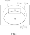
- Fig. 4 is a diagram describing an example of a control of reading of a BM image and an RV image that are images read from a captured image, the control being performed by the controller 43.
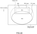
- the captured image (a light-receiving surface of the image sensor 32) includes an image circle of (a lens included in) the optical system 31, as illustrated in, for example, Fig. 4 .
- the controller 43 controls reading of a pixel signal from the image sensor 32 such that a specified region R11 is extracted from a captured image as a BM image, the specified region R11 being a region in which a region situated further rearward than a region just behind the rear of the vehicle 10 appears (a region observed using an interior rearview mirror if the interior rearview mirror is installed in the vehicle 10).
- the controller 43 controls reading of a pixel signal from the image sensor 32 according to a display device or the type (/ an application) of image-display function.
- the controller 43 controls reading of a pixel signal from the image sensor 32 by supplying a reading position for a read image to the image sensor 32, such that a specified region R12 is extracted as an RV image from (an image in the image circle from among) the captured image, the specified region R12 being a region in which the rear of the vehicle 10 and the region just behind the rear of the vehicle 10 appear.
- the image sensor 32 reads, from a captured image obtained by performing image-capturing, a pixel signal of the region R11 that corresponds to (a pixel value of) the BM image, and outputs a read image that exhibits the pixel value corresponding to the pixel signal. Further, the image sensor 32 reads, from the captured image, a pixel signal of the region R12 that corresponds to the RV image, and outputs a read image that exhibits a pixel value corresponding to the pixel signal.
- the regions R11 and R12 are each specified by a reading position for a read image that is supplied from the controller 43 to the image sensor 32.
- the controller 43 can also calculate a reading position according to, for example, positions of the line of sight and the head of a driver that are included in vehicle information, the reading position being used to specify the region R11 extracted as the BM image.
- the controller 43 can also calculate a reading position according to the positions of the line of sight and the head of the driver, such that the driver can see a BM image of a range similar to the range in an image that can be observed when the rearview mirror is installed in the vehicle 10, the reading position being used to specify the region R11 extracted as the BM image.
- Fig. 5 is a diagram describing a first example of a relationship between a state of the vehicle 10 and a BM image.
- Fig. 5(A1) illustrates a state of the vehicle 10 when the vehicle 10 is traveling on a flat road surface. Further, Fig. 5(A2) illustrates an example of a BM image obtained when the vehicle 10 is traveling on the flat road surface.
- Fig. 5(B1) illustrates a state of the vehicle 10 when the vehicle 10 starts traveling downhill. Further, Fig. 5(B2) illustrates an example of a BM image obtained when the vehicle 10 starts traveling downhill.
- Fig. 5(C1) illustrates a state of the vehicle 10 when the vehicle 10 starts traveling uphill. Further, Fig. 5(C2) illustrates an example of a BM image obtained when the vehicle 10 starts traveling uphill.
- the range of a three-dimensional space in the BM image is referred to as a BM range.
- a BM range positions of the line of sight and the head of a driver are fixed in order to simplify the description. Therefore, it is assumed that (a position of) the region R11 extracted as a BM image from a captured image, and thus a BM range are not changed due to the driver moving the position of his/her line of sight or his/her head.
- the controller 43 performs a reading control, that is, a calculation of a reading position (a reading-start position and the size) such that a BM image in which a rear vehicle situated rearward a specified distance from the vehicle 10 appears substantially in the center of the view of the BM image is extracted, as illustrated in Fig. 5 .
- the vehicle 10 when the vehicle 10 starts traveling downhill, the vehicle 10 is inclined to the front, that is, in a pitch direction, and the optical axis of the camera unit 11 installed in the rear of the vehicle 10, and thus the BM range are upwardly inclined (toward the sky), compared to when the vehicle 10 is on a flat road surface ( Fig. 5(B1) and Fig. 5(B2) ).
- a BM image in which the rear vehicle situated rearward the specified distance from the vehicle 10 appears in a lower portion of the view of the BM image is obtained in a state in which the vehicle 10 starts traveling downhill.
- the proportion of the sky is larger and the proportion of a road is smaller in this BM image than a BM image obtained in a state in which the vehicle 10 is on a flat road surface.
- an amount of information is changed in a BM image obtained when the vehicle 10 starts traveling downhill, compared to a BM image obtained when the vehicle 10 is on a flat road surface.
- an amount of information regarding a road is reduced in the BM image obtained when the vehicle 10 starts traveling downhill, compared to the BM image obtained when the vehicle 10 is on a flat road surface.
- the vehicle 10 when the vehicle 10 starts traveling uphill, the vehicle 10 is inclined to the back, that is, in the pitch direction, and the optical axis of the camera unit 11 installed in the rear of the vehicle 10, and thus the BM range are downwardly inclined (toward the road), compared to when the vehicle 10 is on a flat road surface ( Fig. 5(C1) and Fig. 5(C2) ).
- a BM image in which the rear vehicle situated rearward the specified distance from the vehicle 10 appears in an upper portion of the view of the BM image is obtained in a state in which the vehicle 10 starts traveling uphill.
- the proportion of the sky is smaller and the proportion of a road is larger in this BM image than a BM image obtained in a state in which the vehicle 10 is on a flat road surface.
- an amount of information is changed in a BM image obtained when the vehicle 10 starts traveling uphill, compared to a BM image obtained when the vehicle 10 is on a flat road surface.
- an amount of information regarding the sky is reduced in the BM image obtained when the vehicle 10 starts traveling uphill since the proportion of the sky is reduced, compared to the BM image obtained when the vehicle 10 is on a flat road surface.
- the controller 43 controls, according to inclination information from the detector 42, reading of a BM image corresponding to a read image from the image sensor 32, such that a BM image having an amount of information similar to that of a BM image obtained when the vehicle 10 is on a flat road surface, is obtained regardless of a state of the vehicle 10.
- Fig. 6 is a diagram describing an example of a control of reading of a read image that is performed by the controller 43 according to inclination information.
- a reading control is performed by the controller 43 such that (a pixel signal of a pixel of) a rectangular region R101 is read from a captured image captured by the image sensor 32 (from the light-receiving surface of the image sensor 32).
- the region R101 has the same size as a BM image that is a read image.
- the controller 43 performs a reading control such that a reading position used to specify a region R102 having the same size as the region R101 is calculated according to inclination information, and a pixel signal of the calculated reading position is read, the region R102 being shifted upward from the region R101 by the number of pixels corresponding to an angle at which the vehicle 10 is inclined to the back.
- the controller 43 performs a reading control such that a reading position used to specify a region R103 having the same size as the region R101 is calculated according to inclination information, and a pixel signal of the calculated reading position is read, the region R103 being shifted downward from the region R101 by the number of pixels corresponding to an angle at which the vehicle 10 is inclined to the front.
- the reading position is calculated such that a read image in which a road and the sky appear in the same proportion as a BM image obtained when the vehicle 10 is on a flat road surface, is read, that is, such that the proportion between a road and the sky that appear in a read image is maintained the same as (/ is close to) the proportion in a BM image obtained when the vehicle 10 is on a flat road surface.
- the detector 42 detects a (steep) hill from, for example, gyroscopic information, or GPS information and a 3D map that are vehicle information supplied by the acquisition section 41, and detects (calculates) inclination information regarding the vehicle 10 when the vehicle 10 starts going up or down a hill, that is, inclination information that primarily indicates (the level of) the inclinations of the vehicle 10 to the front and to the back, that is, in the pitch direction. Then, the detector 42 supplies the inclination information to the controller 43.
- a (steep) hill from, for example, gyroscopic information, or GPS information and a 3D map that are vehicle information supplied by the acquisition section 41, and detects (calculates) inclination information regarding the vehicle 10 when the vehicle 10 starts going up or down a hill, that is, inclination information that primarily indicates (the level of) the inclinations of the vehicle 10 to the front and to the back, that is, in the pitch direction.
- the detector 42 can detect, using the gyroscopic information, that the vehicle 10 starts going up or down a hill, and can further detect inclination information that indicates the inclinations of the vehicle 10 to the front and to the back, that is, in the pitch direction at that time.
- the detector 42 detects (estimates), from the current location obtained using the GPS information and from the 3D map, that the vehicle 10 starts going up or down a hill, and can further detect (estimate), using an inclination of the hill that is obtained using the 3D map, inclination information that indicates the inclinations of the vehicle 10 to the front and to the back, that is, in the pitch direction when the vehicle 10 starts going up or down the hill.
- the controller 43 calculates a reading position for an image read from the image sensor 32 as a read image, and supplies the calculated reading position to the image sensor 32. Accordingly, the controller 43 controls reading of the read image from the image sensor 32.
- the image sensor 32 reads a pixel signal of a pixel of the reading position supplied from the controller 43, and outputs a read image that exhibits a pixel value corresponding to the pixel signal.
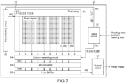
- Fig. 7 illustrates an example of a configuration of the image sensor 32 of Fig. 3 .
- the image sensor 32 includes a pixel array 51, an input circuit 52, a row selecting circuit 53, a column selecting circuit 54, an analog-to-digital (AD) converter 55, a line buffer 56, and an output circuit 57.
- AD analog-to-digital
- the pixel array 51 includes a plurality of pixels 61 arranged in a two-dimensional plane. A region, in the pixel array 51, in which the pixels 61 are arranged is the light-receiving surface of the image sensor 32.
- the pixel 61 converts light entering the pixel 61 into a pixel signal that is an electrical signal corresponding to the amount of the light.
- a pixel signal of the pixel 61 in a row selected by the row selecting circuit 53 and in a column selected by the column selecting circuit 54 is read from the pixel array 51 through the column selecting circuit 54, and the read pixel signal is supplied to the AD converter 55.
- a reading position specified by a reading-start position for a read image read from a captured image and by the size of the read image (hereinafter also referred to as a reading size) is supplied by the controller 43 to the input circuit 52.
- the input circuit 52 calculates coordinates of the pixel 61 from among the pixels 61 of the pixel array 51 that are reading-start coordinates (X_STA,Y_STA), and calculates coordinates of the pixel 61 from among the pixels 61 of the pixel array 51 that are reading-termination coordinates (X_END,Y_END), the pixel 61 for the reading-start coordinates (X_STA,Y_STA) being the pixel 61 at which reading of a pixel signal is started in, for example, raster scan order, the pixel 61 for the reading-termination coordinates (X_END,Y_END) being the pixel 61 at which reading of a pixel signal is terminated in, for example, raster scan order.
- the input circuit 52 supplies a y-coordinate Y_STA of the reading-start coordinates (X_STA,Y_STA), and a y-coordinate Y_END of the reading-termination coordinates (X_END,Y_END) to the row selecting circuit 53, and the input circuit 52 supplies an x-coordinate X_STA of the reading-start coordinates (X_STA,Y_STA) and an x-coordinate X_END of the reading-termination coordinates (X_END,Y_END) to the column selecting circuit 54 (a process PR1).
- the row selecting circuit 53 sequentially selects rows from a row of the pixel 61 represented by the y-coordinate Y_STA received from the input circuit 52 up to a row of the pixel 61 represented by the y-coordinate Y_END received from the input circuit 52 (a process PR2).
- a pixel signal is read from the pixel 61 in the row selected by the row selecting circuit 53, and the read pixel signal is supplied to the column selecting circuit 54.
- the column selecting circuit 54 selects pixel signals of the pixels 61 in respective columns from a column of the pixel 61 represented by the x-coordinate X_STA received from the input circuit 52 up to a column of the pixel 61 represented by the x-coordinate X_END received from the input circuit 52, and the column selecting circuit 54 supplies the selected pixel signals to the AD converter 55 (a process PR3) .
- the AD converter 55 performs AD conversion on a pixel signal from the column selecting circuit 54, for example, per row, and supplies, to the line buffer 56, the pixel signal on which AD conversion has been performed (a process PR4) .
- the line buffer 56 temporarily stores therein a pixel signal from the AD converter 55.
- the output circuit 57 reads a pixel signal stored in the line buffer 56 for each pixel (a process PR5), and outputs the read pixel signal to the outside of the image sensor 32 as a pixel value of the read image.
- a pixel signal of the pixel 61 included in a read region is read, and an image that exhibits a pixel value corresponding to the pixel signal is read as a read image, the read region being a rectangular region that includes the pixel 61 of the reading-start coordinates (X_STA, Y_STA) as an upper-left vertex and the pixel 61 of the reading-termination coordinates (X_END, Y_END) as a lower-right vertex.
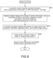
- Fig. 8 is a flowchart describing an example of display processing of displaying a BM image that is performed in the first example of the configuration of the viewing system of Fig. 3 .
- Step S11 the acquisition section 41 acquires gyroscopic information, or GPS information and a 3D map as vehicle information, and supplies the vehicle information to the detector 42. Then, the process moves on to Step S12.
- Step S12 the detector 42 detects a hill using the vehicle information from the acquisition section 41. Further, the detector 42 detects (calculates), using the vehicle information from the acquisition section 41, inclination information regarding the vehicle 10 when the vehicle 10 starts going up or down the hill (primarily, inclination information indicating the inclinations to the front and to the back, that is, in the pitch direction), and supplies the detected inclination information to the controller 43. Then, the process moves on to Step S13 from Step S12.
- Step S13 the controller 43 calculates, according to the inclination information from the detector 42, a reading-start position for a read image from the image sensor 32, and supplies the reading-start position and the size of a BM image to the image sensor 32 as a reading position. Then, the process moves on to Step S14.
- Step S14 the image sensor 32 reads a pixel signal of a pixel of the reading position supplied by the controller 43, and acquires a read image that exhibits a pixel value corresponding to the pixel signal to output the acquired read image.
- the read image output by the image sensor 32 is supplied to the output section 33, and the process moves on to Step S15 from Step S14.
- Step S15 the output section 33 transmits, to the BM display section 21 and as a BM image, the read image from the image sensor 32, and causes the read image to be displayed on the BM display section 21. This results in the BM image being displayed on the BM display section 21, and the displaying processing is terminated.
- inclination information is detected that primarily indicates the inclinations to the front and to the back, that is, in the pitch direction, and reading of a read image from the image sensor 32 is controlled according to the inclination information.
- a BM image having an amount of information similar to that of a BM image obtained when the vehicle 10 is on a flat road surface can be easily provided when the vehicle 10 starts going up or down a hill.
- a read image having the same size as a BM image is read from the image sensor 32 in the reading control.
- Gyroscopic information as well as GPS information and a 3D map have been described as examples of the vehicle information in the first configuration example.
- suspension information, a front camera image, or the like may be used as the vehicle information in the first configuration example.
- the inclination of the vehicle may be detected using the suspension information, the front camera image, or the like.
- Fig. 9 is a block diagram illustrating the second example of the configuration of the viewing system included in the vehicle 10.
- the viewing system includes the camera unit 11, the BM display section 21, and the RV display section 22. Further, the camera unit 11 in Fig. 9 includes the optical system 31, the image sensor 32, the output section 33, the acquisition section 41, the detector 42, a controller 71, and a processing section 72.
- the second example of the configuration of the viewing system of Fig. 9 is similar to the configuration of the viewing system of Fig. 3 in including the camera unit 11, the BM display section 21, and the RV display section 22.
- the second example of the configuration of the viewing system of Fig. 9 is different from the configuration of the viewing system of Fig. 3 in that the camera unit 11 includes the controller 71 instead of the controller 43, and newly includes the processing section 72.
- the controller 71 controls reading of a read image from the image sensor 32 according to inclination information supplied by the detector 42.
- the controller 71 calculates a reading-start position for and the reading size of a read image from a captured image captured by the image sensor 32, and the controller 71 supplies a reading position specified by the reading-start position and the reading size to the image sensor 32.
- the reading size is set to the size of a BM image since the size of a read image is the same as the size of the BM image.
- the reading size is calculated according to inclination information.
- the acquisition section 41 acquires, for example, suspension information as vehicle information, and supplies the acquired vehicle information to the detector 42.
- the detector 42 detects the inclination to the left and to the right, that is, in a roll direction using the suspension information from the acquisition section 41, and detects (calculates) inclination information that indicates (the level of) the inclination. Then, the detector 42 supplies the inclination information to the controller 71.
- the controller 71 calculates a rotation angle used to rotate the read image output by the image sensor 32, and supplies the calculated rotation angle to the processing section 72.
- the controller 71 supplies the rotation angle to the processing section 72 as described above to control a rotation of a read image that is performed by the processing section 72, such that the read image is rotated by the rotation angle.
- the read image output by the image sensor 32 is supplied to the processing section 72.
- the processing section 72 rotates the read image according to the rotation angle from the controller 71. Further, the processing section 72 cuts an image having a size of a BM image (hereinafter also referred to as a BM size) out of the rotated read image, and supplies the obtained image to the output section 33 as the BM image.
- a BM image hereinafter also referred to as a BM size
- a read image is rotated and an image having a BM size is cut out of the rotated read image.
- the read image be an image having a size in which an image having a BM size can be cut out of the read image after rotation.
- the controller 71 calculates, as a reading size and according to inclination information, a smallest size of a read image such that an image having a BM size can be cut out of the read image after rotation.
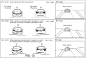
- Fig. 10 is a diagram describing a second example of a relationship between a state of the vehicle 10 and a BM image.
- Fig. 10(A1) illustrates a state of the vehicle 10 when the vehicle 10 is traveling on a flat road surface. Further, Fig. 10(A2) illustrates an example of a BM image obtained when the vehicle 10 is traveling on the flat road surface.
- Fig. 10(B1) illustrates a state of the vehicle 10 when the vehicle 10 is on a road surface that has a difference in level and of which the right side is higher than its left side in a direction in which a front side of the vehicle 10 is oriented.
- Fig. 10(B2) illustrates an example of a BM image obtained when the vehicle 10 is on the road surface that has a difference in level and of which the right side is higher than its left side in the direction in which the front side of the vehicle 10 is oriented.
- Fig. 10(C1) illustrates a state of the vehicle 10 when the vehicle 10 is on a road surface that has a difference in level and of which the left side is higher than its right side in the direction in which the front side of the vehicle 10 is oriented.
- Fig. 10(C2) illustrates an example of a BM image obtained when the vehicle 10 is on the road surface that has a difference in level and of which the left side is higher than its right side in the direction in which the front side of the vehicle 10 is oriented.
- the vehicle 10 when the vehicle 10 is on a road surface that has a difference in level and of which the right side is higher than its left side in the direction in which the front side of the vehicle 10 is oriented, the vehicle 10 is inclined to the left, that is, in the roll direction, and the camera unit 11 installed in the rear of the vehicle 10 is also inclined in the roll direction.
- the vehicle 10 when the vehicle 10 is on a road surface that has a difference in level and of which the left side is higher than its right side in the direction in which the front side of the vehicle 10 is oriented, the vehicle 10 is inclined to the right, that is, in the roll direction, and the camera unit 11 installed in the rear of the vehicle 10 is also inclined in the roll direction.
- the controller 71 controls, according to inclination information from the detector 42, reading of a BM image corresponding to a read image from the image sensor 32, such that a BM image having an amount of information similar to that of a BM image obtained when the vehicle 10 is on a flat road surface, is obtained regardless of a state of the vehicle 10.
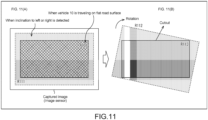
- Fig. 11 is a diagram describing an example of a control of reading of a read image that is performed by the controller 71 according to inclination information.
- Fig. 11(A) on the left illustrates read regions on the image sensor 32 with respect to respective cases.
- Fig. 11(B) on the right illustrates a region cut out by the processing section 72.
- a reading control is performed by the controller 71 such that (a pixel signal of a pixel of) the rectangular region R101 having the same size as a BM image is read from a captured image captured by the image sensor 32 (from the light-receiving surface of the image sensor 32).
- the controller 71 performs a reading control such that a reading position used to specify a region R111 that is larger in size than the region R101 by the number of pixels corresponding to an angle of the inclination of the vehicle 10 in the roll direction, is calculated according to inclination information, and a pixel signal of the calculated reading position is read.
- the horizonal line that appears to extend horizontally in a BM image obtained when the vehicle 10 is on a flat road surface is inclined in a BM image obtained when the vehicle 10 is inclined in the roll direction.
- a read image output by the image sensor 32 according to a reading control is rotated by the processing section 72 such that the horizontal line appearing in the read image extends horizontally, and (an image that corresponds to) the BM image is cut out of the rotated read image.
- a reading-start position and a reading size that are a reading position used to specify the region R111 being centered at the center (the center of gravity) of the region R101 and having a smallest size such that a BM image can be cut out of a read image after rotation, are calculated by the controller 71, and the calculated reading-start position and reading size are supplied to the image sensor 32.
- a rotation angle used to rotate the region R111 corresponding to a read image output by the image sensor 32 is calculated by the controller 71 according to inclination information, such that the horizontal line appearing in the region R111 corresponding to the read image, appears to extend horizontally, and the calculated rotation angle is supplied by the controller 71 to the processing section 72.
- the rectangular region R111 specified by the reading-start position and the reading size that are the reading position from the controller 71 is read by the image sensor 32 as a read image, and is supplied by the image sensor 32 to the processing section 72.
- the region R111 that is the read image from the image sensor 32 is rotated by the processing section 72 by the rotation angle from the controller 71. Then, a region R113 that has the same size as the BM image and of which the angle of rotation is 0 degrees, is cut out of a region R112 by the processing section 72 as the BM image, the region R112 being obtained by rotating the region R111 ( Fig. 11(B) ).
- the vehicle 10 is inclined to the right, that is, in the roll direction, and thus the horizontal line appearing in the read image is inclined diagonally upward right.
- the region R111 that is the read image is rotated clockwise by the processing section 72 such that the horizontal line inclined diagonally upward right extends horizontally, and the region R113 that is a BM image is cut out of the region R112 by the processing section 72, the region R112 being obtained by the rotation.
- a BM image an image suitable for the operation of the vehicle 10.
- a BM image having an amount of information similar to that of a BM image obtained when the vehicle 10 is on a flat road surface, regardless of the inclination of the vehicle 10 in the roll direction.
- Fig. 12 is a diagram further describing an example of the control of reading of a read image that is performed by the controller 71 according to inclination information.
- Fig. 12(A) is a diagram describing the fact that the reading size of a read image obtained when the vehicle 10 is inclined in the roll direction is larger than the size of a BM image.
- Fig. 12(B) is a diagram describing a rotation performed by the processing section 72.
- Fig. 12(C) is a diagram describing a cutout of the BM image that is performed by the processing section 72.
- Fig. 12(A) the vehicle 10 is inclined to the right, that is, in the roll direction, and thus the horizontal line appearing in the read image is inclined diagonally upward right.
- the detector 42 detects, from suspension information that is vehicle information and is supplied by the acquisition section 41, that the vehicle 10 is inclined in the roll direction, and detects (calculates) inclination information that indicates the inclination of the vehicle 10, that is, inclination information that primarily indicates (the level of) the inclinations of the vehicle 10 to the left and to the right, that is, in the roll direction. Then, the detector 42 supplies the inclination information to the controller 71.
- the controller 71 calculates a reading-start position for and the reading size of the region R111 represented by a reading position for a read image read from the image sensor 32, and the controller 71 supplies the calculated reading-start position and reading size to the image sensor 32.
- the reading size is larger than the size of the region R101 having the same size as the BM image.
- the controller 71 calculates a rotation angle used to rotate the region R111 that is the read image, and supplies the calculated rotation angle to the processing section 72.
- the image sensor 32 reads, as a read image, the region R111 represented by the reading position (the reading-start position and the reading size) from the controller 71, and outputs the read image.
- the region R111 that is the read image output by the image sensor 32 is supplied to the processing section 72.
- the region R111 is rotated by the processing section 72 by the rotation angle from the controller 71, and this results in generating the region R112 in which the horizontal line appears to extend horizontally ( Fig. 12(B) ). Further, the region R113 having the same size as the region R101 is cut out of the region R112 by the processing section 72 as a BM image ( Fig. 12(B) and Fig. 12(C) ).
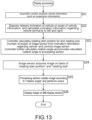
- Fig. 13 is a flowchart describing an example of display processing of displaying a BM image that is performed in the second example of the configuration of the viewing system of Fig. 9 .
- Step S21 the acquisition section 41 acquires suspension information as vehicle information, and supplies the vehicle information to the detector 42. Then, the process moves on to Step S22.
- Step S22 the detector 42 detects the inclination of the vehicle 10 in the roll direction using the vehicle information from the acquisition section 41. Further, the detector 42 detects (calculates), using the vehicle information from the acquisition section 41, inclination information regarding the vehicle 10 when the vehicle 10 is inclined in the roll direction (primarily, inclination information indicating the inclinations to the left and to the right, that is, in the roll direction), and supplies the detected inclination information to the controller 71. Then, the process moves on to Step S23 from Step S22.
- Step S23 the controller 71 calculates, according to the inclination information from the detector 42, a reading-start position for and the reading size of a read image from the image sensor 32, and supplies the reading-start position and the reading size to the image sensor 32 as a reading position. Further, the controller 71 calculates, according to the inclination information from the detector 42, a rotation angle used to rotate the read image, and supplies the calculated rotation angle to the processing section 72. Then, the process moves on to Step S24 from Step S23.
- Step S24 the image sensor 32 reads a pixel signal of a pixel of the reading position supplied by the controller 71, and acquires a read image that exhibits a pixel value corresponding to the pixel signal to output the acquired read image.
- the read image output by the image sensor 32 is supplied to the processing section 72, and the process moves on to Step S25 from Step S24.
- Step S25 the processing section 72 rotates the read image from the image sensor 32 by the rotation angle from the controller 71. Further, the processing section 72 cuts a BM image out of the rotated read image, and supplies the BM image to the output section 33. Then, the process moves on to Step S26 from Step S25.
- Step S26 the output section 33 transmits, to the BM display section 21, the BM image from the processing section 72, and causes the BM image to be displayed on the BM display section 21. This results in the BM image being displayed on the BM display section 21, and the displaying processing is terminated.
- inclination information is detected that primarily indicates the inclinations to the left and to the right, that is, in the roll direction, and reading of a read image from the image sensor 32 is controlled according to the inclination information.
- a rotation of the read image is controlled according to the inclination information, and a BM image is cut out of the read image after the rotation.
- a BM image having an amount of information similar to that of a BM image obtained when the vehicle 10 is on a flat road surface can be easily provided when the vehicle 10 is on a road surface having a difference in level between the left side and the right side.
- a read image having a smallest size such that a BM image can be cut out of the read image after rotation is read from the image sensor 32 in the reading control. This makes it possible to reduce the possibility of reducing the frame rate of the BM image.
- the suspension information has been described as an example of the vehicle information in the second configuration example.
- the gyroscopic information; the GPS information and the 3D map; the front camera image; or the like may be used as the vehicle information, as in the first configuration example described above, or in the third configuration example described later.
- the inclination of the vehicle may be detected using the gyroscopic information; the GPS information and the 3D map; the front camera image; or the like.
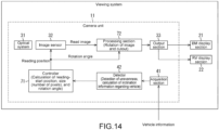
- Fig. 14 is a block diagram illustrating the third example of the configuration of the viewing system included in the vehicle 10.
- the viewing system includes the camera unit 11, the BM display section 21, and the RV display section 22. Further, the camera unit 11 in Fig. 14 includes the optical system 31, the image sensor 32, the output section 33, the acquisition section 41, the detector 42, the controller 71, and the processing section 72.
- the third example of the configuration of the viewing system of Fig. 14 is similar to the second example of the configuration of the viewing system of Fig. 9 .
- the acquisition section 41 acquires, for example, suspension information or a front camera image as vehicle information, and supplies the acquired vehicle information to the detector 42.
- the detector 42 detects a state of the unevenness of a road surface using the suspension information or the front camera image from the acquisition section 41. Further, the detector 42 detects the inclinations of the vehicle 10 to the front and to the back, that is, in the pitch direction as well as the inclinations of the vehicle 10 to the left and to the right, that is, in the roll direction due to the unevenness of the road surface, and detects (calculates) inclination information that indicates (the levels of) the inclinations. Then, the detector 42 supplies the inclination information to the controller 71.
- reading of a read image from the image sensor 32 is controlled according to the inclinations of the vehicle 10 to the front and to the back, that is, in the pitch direction.
- reading of a read image from the image sensor 32, and a rotation of the read image that is performed by the processing section 72 are controlled according to the inclination of the vehicle 19 to the left and the right, that is, in the roll direction.
- reading of a read image from the image sensor 32, and a rotation of the read image that is performed by the processing section 72 are controlled according to the inclinations of the vehicle 10 to the front and to the back, that is, in the pitch direction, and according to the inclinations of the vehicle 10 to the left and to the right, that is, in the roll direction.
- a control obtained by combining the controls of reading of a read image from the image sensor 32 that are respectively performed in the first and second examples of the configuration of the viewing system is performed as a control of reading of a read image from the image sensor 32.
- the same control as the control of a rotation of a read image that is performed in the second example of the configuration of the viewing system is performed as a control of a rotation of a read image that is performed by the processing section 72.
- Fig. 15 is a diagram describing an example of a control of reading of a read image that is performed by the controller 71 according to inclination information.
- Fig. 15(A) illustrates reading of a read image that is larger in size than a BM image from the image sensor 32.
- Fig. 15(B) illustrates a rotation of the read image and a cutout that are performed by the processing section 72.
- a reading control is performed by the controller 71 such that (a pixel signal of a pixel of) the rectangular region R101 having the same size as a BM image that is a read image, is read from a captured image captured by the image sensor 32 (from the light-receiving surface of the image sensor 32).
- the controller 71 controls reading performed by the image sensor 32 such that a reading position used to specify a region R121 is calculated according to inclination information and a pixel signal of the calculated reading position is read, the region R121 being larger in size than the region R111 by the number of pixels corresponding to an angle of the inclination of the vehicle 10 in the roll direction, the region R121 being upwardly or downwardly offset from the region R111 by the number of pixels corresponding to an angle of the inclination of the vehicle 10 in the pitch direction.
- a rotation angle used to rotate the region R121 corresponding to a read image output by the image sensor 32 is calculated by the controller 71 according to inclination information, such that the horizontal line appearing in the region R121 corresponding to the read image, appears to extend horizontally, and the calculated rotation angle is supplied by the controller 71 to the processing section 72.
- the rectangular region R121 is read by the image sensor 32 as a read image in accordance with the reading control performed by the controller 71, and is supplied by the image sensor 32 to the processing section 72.
- the region R121 that is the read image from the image sensor 32 is rotated by the processing section 72 by the rotation angle from the controller 71. Then, a region R123 that has the same size as a BM image and of which the angle of rotation is 0 degrees, is cut out of a region R122 by the processing section 72 as the BM image, the region R122 being obtained by rotating the region R121.
- the vehicle 10 is inclined to the back, that is, in the pitch direction, and is inclined to the right, that is, in the roll direction.
- the region R121 that is larger in size than the region R101 and is upwardly offset from the region R101 is read from the image sensor 32 as a read image.
- the vehicle 10 is inclined to the right, that is, in the roll direction, and thus the horizontal line appearing in the region R121 that is the read image is inclined diagonally upward right.
- the region R121 that is the read image is rotated clockwise by the processing section 72 such that the horizontal line inclined diagonally upward right extends horizontally.
- the region R123 that is a BM image is cut out of the region R122 by the processing section 72, the region R122 being obtained by rotating the region R121.
- a BM image an image suitable for the operation of the vehicle 10.
- a BM image exhibiting image representation similar to that of a BM image obtained when the vehicle 10 is on a flat road surface, regardless of the inclination of the vehicle 10 in the pitch direction and the inclination of the vehicle 10 in the roll direction.
- This makes it possible to display an image in which the horizontal line extends horizontally regardless of the inclination of the vehicle 10.
- the detector 42 can detect the inclinations of the vehicle 10 in the pitch direction and in the roll direction from, for example, suspension information.
- the detector 42 can recognize the unevenness of a road surface ahead of the vehicle 10 from, for example, a front camera image, and, according to a result of recognizing the unevenness, the detector 42 can estimate to detect the inclinations of the vehicle 10 in the pitch direction and in the roll direction when the vehicle 10 travels on the road surface having the recognized unevenness.
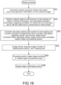
- Fig. 16 is a flowchart describing an example of display processing of displaying a BM image that is performed in the third example of the configuration of the viewing system of Fig. 14 .
- Step S31 the acquisition section 41 acquires suspension information or a front camera image as vehicle information, and supplies the vehicle information to the detector 42. Then, the process moves on to Step S32.
- Step S32 the detector 42 detects, using the vehicle information from the acquisition section 41, a state of the unevenness of a road surface on which the vehicle 10 is situated. Further, the detector 42 detects (calculates), using the vehicle information from the acquisition section 41, inclination information that indicates the inclination of the vehicle 10 due to the unevenness of a road surface (the inclinations to the front and to the back, that is, in the pitch direction, and the inclinations to the left and to the right, that is, in the roll direction), and supplies the detected inclination information to the controller 71. Then, the process moves on to Step S33 from Step S32.
- Step S33 the controller 71 calculates, according to the inclination information from the detector 42, a reading-start position for and the reading size of a read image from the image sensor 32, and supplies the reading-start position and the reading size to the image sensor 32 as a reading position. Further, the controller 71 calculates, according to the inclination information from the detector 42, a rotation angle used to rotate the read image, and supplies the calculated rotation angle to the processing section 72. Then, the process moves on to Step S34 from Step S33.
- Step S34 the image sensor 32 reads a pixel signal of a pixel of the reading position supplied by the controller 71, and acquires a read image that exhibits a pixel value corresponding to the pixel signal to output the acquired read image.
- the read image output by the image sensor 32 is supplied to the processing section 72, and the process moves on to Step S35 from Step S34.
- Step S35 the processing section 72 rotates the read image from the image sensor 32 by the rotation angle from the controller 71. Further, the processing section 72 cuts a BM image out of the rotated read image, and supplies the BM image to the output section 33. Then, the process moves on to Step S36 from Step S35.
- Step S36 the output section 33 transmits, to the BM display section 21, the BM image from the processing section 72, and causes the BM image to be displayed on the BM display section 21. This results in the BM image being displayed on the BM display section 21, and the displaying processing is terminated.
- inclination information is detected that indicates the inclinations to the front and to the back, that is, in the pitch direction as well as the inclinations to the left and to the right, that is, in the roll direction, and reading of a read image from the image sensor 32 is controlled according to the inclination information.
- a rotation of the read image is controlled according to the inclination information, and a BM image is cut out of the read image after the rotation.
- a read image having a smallest size such that a BM image can be cut out of the read image after rotation is read from the image sensor 32 in the reading control, as in the second example of the configuration of the viewing system. This makes it possible to reduce the possibility of reducing the frame rate of the BM image.
- the suspension information and the front camera image have been described as examples of the vehicle information in the third configuration example.
- the gyroscopic information; the GPS information and the 3D map; or the like may be used as the vehicle information, as in the first or second configuration example described above.
- the inclination of the vehicle may be detected using the gyroscopic information; the GPS information and the 3D map; or the like.
- the present technology is applicable not only to the case in which the vehicle 10 is inclined according to a state of a road surface on which the vehicle 10 is situated, but also to the case in which the vehicle 10 is inclined according to, for example, an object loaded on the vehicle 10 or a state of an occupant of the vehicle 10. In other words, the present technology is applicable regardless of a cause for the inclination of the vehicle 10.
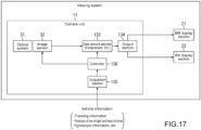
- Fig. 17 is a block diagram illustrating a fourth example of the configuration of the viewing system included in the vehicle 10.
- the viewing system includes the camera unit 11, the BM display section 21, and the RV display section 22 described with reference to Figs. 1 and 2 .
- the camera unit 11 includes the optical system 31, the image sensor 32, a data amount adjuster 133, an output section 134, an acquisition section 135, and a controller 136.
- the optical system 31 includes optical components such as a condenser and a diaphragm, and collects light entering the optical system 31 onto the image sensor 32.
- the image sensor 32 receives light from the optical system 31 and performs photoelectric conversion to capture a captured image. Then, in accordance with control performed by the controller 136, the image sensor 32 extracts a BM image and an RV image from the captured image to output the extracted images. The BM image and the RV image that are output by the image sensor 32 are supplied to the data amount adjuster 133.
- the data amount adjuster 133 adjusts data amounts of the BM image and the RV image that are output by the image sensor 32, and supplies, to the output section 134, the BM image and the RV image of which the respective data amounts have been adjusted.
- the output section 134 is an output interface (IF) that transmits, to the outside of the camera unit 11, the BM image and the RV image from the data amount adjuster 133.
- the output section 134 transmits the BM image to the BM display section 21, and transmits the RV image to the RV display section 22.
- the BM image from the output section 134 is displayed on the BM display section 21 in accordance with the specification of the BM display section 21, and the RV image from the output section 134 is displayed on the RV display section 22 in accordance with the specification of the RV display section 22.
- the output section 134 is capable of performing a format conversion and other image processing on the BM image and the RV image as necessary.
- the acquisition section 135 acquires vehicle information from the vehicle 10, and supplies the acquired vehicle information to the controller 136.
- Examples of the vehicle information acquired by the acquisition section 135 include traveling information, the specifications of the BM display section 21 and the RV display section 22, positions of the line of sight and the head of a driver of the vehicle 10, and gyroscopic information.
- the traveling information is information that indicates a traveling state of the vehicle 10, and specifically indicates a vehicle speed and a traveling direction (forward or backward). For example, it is possible to acquire the vehicle speed from output of a speed sensor when the vehicle 10 includes the speed sensor. For example, it is possible to acquire the traveling direction from a state of the transmission.
- the specifications of the BM display section 21 and the RV display section 22 are the resolution of the BM display section 21 and the resolution of the RV display section 22, and can be acquired from the BM display section 21 and the RV display section 22.
- the positions of the line of sight and the head of a driver of the vehicle 10 are obtained from an image captured by the in-vehicle camera 23.
- the gyroscopic information is information that indicates a pose of the vehicle 10 (/ an angle of the inclination of the vehicle). It is possible to obtain the gyroscopic information from output of a gyroscope when the vehicle 10 includes the gyroscope. The use of the gyroscopic information makes it possible to recognize whether the vehicle 10 is on a hill.
- the controller 136 controls the image sensor 32 and the data amount adjuster 133 according to the vehicle information supplied by the acquisition section 135.
- the controller 136 performs a reading control similar to the reading control performed by the controller 43, according to the vehicle information. Accordingly, the controller 136 performs an extraction control for controlling extraction of a BM image and an RV image from a captured image captured by the image sensor 32. Examples of ranges of reading the BM image and the RV image include the ranges illustrated in Fig. 4 . Further, according to the vehicle information, the controller 136 performs an adjustment control for controlling adjustment of data amounts of the BM image and the RV image that is performed by the data amount adjuster 133.
- the image sensor 32 extracts a BM image and an RV image from a captured image according to vehicle information, and the data amount adjuster 133 adjusts data amounts of the BM image and the RV image according to the vehicle information.
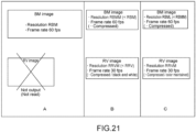
- Fig. 18 illustrates an example of an image that can be output by the image sensor 32.
- a highest-resolution captured image that can be output by the image sensor 32 is referred to as a highest-resolution image. It is assumed that, for example, the image sensor 32 has the ability to output a highest-resolution image of a resolution (the number of pixels) Rmax at (a frame rate of) 60 fps (frame per second) or more.
- a resolution RBM for a highest-resolution BM image (a BM image of a largest number of pixels) that is extracted from the highest-resolution image is equal to or less than 1/2 of the resolution Rmax for the highest-resolution image. It is also assumed that a resolution RRV for a highest-resolution RV image that is extracted from the highest-resolution image is equal to or less than the resolution RBM for the BM image.
- a sum RBM+RRV of the resolution RBM for a BM image and the resolution RRV for an RV image is equal to or less than 1/2 of the resolution Rmax for the highest-resolution image.
- the use of the image sensor 32 capable of outputting a highest-resolution image of the resolution Rmax at 60 fps (or more) makes it possible to output both the BM image of the resolution RBM and the RV image of the resolution RRV at 120 fps, the BM image and the RV image being obtained by partially reading the high-resolution image.
- Fig. 19 is a diagram describing an example of a vehicle transmission bandwidth that can be used for data transmission in the vehicle 10.
- Fig. 19 illustrates examples of a BM image and an RV image that can be output by the camera unit 11 without data amounts being adjusted by the data amount adjuster 133.
- the camera unit 11 can output, as a BM image, a color image of the resolution RBM in a YUV 4:2:2 format in which the number of bits per pixel is eight (with respect to each of the brightness and a difference in color). Further, for example, the camera unit 11 can output, as an RV image, a color image of the resolution RRV in the YUV 4:2:2 format in which the number of bits per pixel is eight.
- the BM image of the resolution RBM in the YUV 4:2:2 format in which the number of bits per pixel is eight is referred to as a highest-quality BM image
- the RV image of the resolution RRV in the YUV 4:2:2 format in which the number of bits per pixel is eight is referred to as a highest-quality RV image.
- the vehicle transmission bandwidth which is a bandwidth in which data is transmitted from the camera unit 11, is a transmission bandwidth in which, for example, two screens of a highest-quality BM image at 60 fps can be transmitted (in real time).
- the vehicle transmission bandwidth in which two screens of a highest-quality BM image at 60 fps can be transmitted makes it possible to transmit, for example, two screens of a highest-quality RV image at 60 fps, since RBM ⁇ RRV.
- the vehicle transmission bandwidth makes it possible to transmit, for example, two screens in total that are a single screen of the highest-quality BM image at 60 fps, and a single screen of the highest-quality RV image at 60 fps.
- the camera unit 11 is capable of outputting both a highest-quality BM image and a highest-quality RV image at up to 120 fps.
- the vehicle transmission bandwidth only makes it possible to transmit two screens of a highest-quality BM image (or RV image) at 60 fps.
- the increase in vehicle transmission bandwidth makes it possible to transmit both a highest-quality BM image and a highest-quality RV image at 120 fps that can be output by the camera unit 11.
- the increase in vehicle transmission bandwidth results in increasing the costs for the viewing system.
- the camera unit 11 appropriately adjusts data amounts of a BM image and an RV image to transmit the BM image and the RV image in the vehicle transmission bandwidth, in order to suppress an increase in the costs for the viewing system.
- Fig. 20 is a diagram describing a first example of a control of adjustment of data amounts of a BM image and an RV image, the control being performed by the controller 136.
- a of Fig. 20 illustrates the adjustment control performed when the vehicle 10 is traveling forward, or is traveling backward at a high speed that is a speed equal to or greater than a first threshold for speed.
- the controller 136 performs an adjustment control that is a control of the data amount adjuster 133, such that a BM image of the resolution RBM at 120 fps is output and output of an RV image is restricted.
- the data amount adjuster 133 adjusts data amounts of a BM image and an RV image from the image sensor 32 to output the BM image of the resolution RBM at 120 fps and to restrict output of the RV image.
- the BM image of the resolution RBM at 120 fps is output from the camera unit 11, and the RV image is not output from the camera unit 11. Consequently, the BM image of the resolution RBM at 120 fps is displayed on the BM display section 21, and the RV image is not displayed on the RV display section 22.
- a driver can confirm a region situated further rearward than a region just behind the rear of the vehicle 10, using a BM image of the resolution RBM at 120 fps, that is, a high-resolution BM image at a high frame rate.
- a BM image of the resolution RBM at 120 fps that is output by the camera unit 11 can be transmitted in the vehicle transmission bandwidth in which two screens of a highest-quality BM image (of the resolution RBM) at 60 fps can be transmitted.
- examples of a data amount adjusting method for adjusting a data amount of an image that is performed by the data amount adjuster 133 include a method for reducing resolution (the number of pixels), a method for reducing gradation (the number of bits per pixel), a method for reducing a frame rate, and a compression method using a specified compression-encoding approach, in addition to the method for restricting output of an image (not outputting an image) as described above.
- a restriction of output of an image, a reduction in resolution, a reduction in gradation, and a reduction in frame rate from among the data amount adjusting methods can be performed by the image sensor 32 by the controller 136 performing control such as a control of extraction performed by the image sensor 32.
- the restriction of output of an image such as a restriction of output of an RV image can be performed by the controller 136 controlling reading of data from the image sensor 32 and not reading a pixel signal corresponding to the RV image from the pixel 51 ( Fig. 7 ), such that extraction of an RV image from a captured image is restricted.
- the controller 136 can control, according to vehicle information, extraction performed by the image sensor 32 such that extraction of an RV image from a captured image is restricted.
- output of an RV image may be restricted by the data amount adjuster 133, not by the image sensor 32.
- the resolution of an image can be reduced by, for example, the controller 136 controlling the image sensor 32 such that the number of pixels 51 from which a pixel signal is read is reduced, or such that binning for adding pixel signals of a plurality of pixels 51 is performed by performing, for example, a so-called source follower (SF) addition or floating diffusion (FD) addition.
- SF source follower
- FD floating diffusion
- the gradation can be reduced by, for example, the controller 136 controlling the image sensor 32 such that the number of bits necessary for AD conversion performed by the AD converter 55 ( Fig. 7 ) is reduced.
- the frame rate can be reduced by, for example, the controller 136 controlling the image sensor 32 such that a rate at which a pixel signal is read from the pixel 51, or a rate at which AD conversion is performed by the AD converter 55 is reduced.
- B of Fig. 20 illustrates the adjustment control performed when the vehicle 10 is traveling backward at a medium speed that is a speed that is less than the first threshold and is equal to or greater than a second threshold less than the first threshold.
- the controller 136 performs an adjustment control that is a control of the data amount adjuster 133 such that a BM image of a resolution RBMM at 120 fps is output and an RV image of a resolution RRVM at 30 fps is output, the resolution RBMM being less than the resolution RBM, the resolution RRVM being less than the resolution RRV.
- the data amount adjuster 133 adjusts data amounts of a BM image and an RV image from the image sensor 32 to output the BM image of the resolution RBMM at 120 fps and to output the RV image of the resolution RRVM at 30 fps.
- the BM image of the resolution RBMM at 120 fps and the RV image of the resolution RRVM at 30 fps are output by the camera unit 11. Consequently, the BM image of the resolution RBMM at 120 fps is displayed on the BM display section 21, and the RV image of the resolution RRVM at 30 fps is displayed on the RV display section 22.
- a driver can confirm a region situated further rearward than a region just behind the rear of the vehicle 10, using a BM image of the resolution RBMM at 120 fps, that is, a medium-resolution BM image at the high frame rate. Further, the driver can confirm the region just behind the rear of the vehicle 10, using an RV image of the resolution RRVM at 30 fps, that is, a medium-resolution RV image at a low frame rate.
- a transmission bandwidth necessary to transmit an RV image of the resolution RRVM at 30 fps is equal to or less than a transmission bandwidth for a difference between a maximum transmission rate (here, a transmission rate necessary to transmit a BM image of the resolution RBM at 120 fps without compressing the BM image) and a transmission rate (a first transmission rate) necessary to transmit the resolution RBMM at 120 fps.
- a maximum transmission rate here, a transmission rate necessary to transmit a BM image of the resolution RBM at 120 fps without compressing the BM image
- a transmission rate a first transmission rate
- one of the BM image and the RV image or both of them can be compressed (compression-encoded) by the data amount adjuster 133 such that the transmission bandwidth necessary to transmit the RV image of the resolution RRVM at 30 fps is equal to or less than the transmission bandwidth for the difference between the maximum transmission rate and the first transmission rate (such that the RV image of the resolution RRVM can be transmitted).
- the transmission bandwidth necessary to transmit the RV image of the resolution RRVM at 30 fps is equal to or less than the transmission bandwidth for the difference between the maximum transmission rate and the first transmission rate (such that the RV image of the resolution RRVM can be transmitted).
- a portion of or all of the BM image is compressed (compression-encoded).
- the RV image is compression-encoded in a state of remaining a color image, or is converted into a black-and-white image to be compression-encoded. This results in being able to reduce a data amount of the RV image.
- FIG. 20 illustrates the adjustment control performed when the vehicle 10 is traveling backward at a low speed that is a speed that is less than the second threshold less than the first threshold.
- the controller 136 performs an adjustment control that is a control of the data amount adjuster 133 such that a BM image of the resolution RBM at 60 fps is output and an RV image of the resolution RRV at 60 fps is output.
- the data amount adjuster 133 adjusts data amounts of a BM image and an RV image from the image sensor 32 to output the BM image of the resolution RBM at 60 fps and to output the RV image of the resolution RRV at 60 fps.
- the BM image of the resolution RBM at 60 fps and the RV image of the resolution RRV at 60 fps are output by the camera unit 11. Consequently, the BM image of the resolution RBM at 60 fps is displayed on the BM display section 21, and the RV image of the resolution RRV at 60 fps is displayed on the RV display section 22.
- a driver can confirm a region situated further rearward than a region just behind the rear of the vehicle 10, using a BM image of the resolution RBM at 60 fps, that is, a high-resolution BM image at a medium frame rate. Further, the driver can confirm the region just behind the rear of the vehicle 10, using an RV image of the resolution RRV at 60 fps, that is, a high-resolution RV image at the medium frame rate.
- the case in which the vehicle 10 is traveling backward at the low speed is, for example, a case in which a driver is about to park the vehicle 10, and it is important to confirm a region just behind the rear of the vehicle 10 that is a blind spot as viewed from the driver.
- an RV image is displayed at a higher resolution and at a higher frame rate, compared to when the vehicle 10 is traveling backward at the high speed or the medium speed. This makes it possible to easily confirm a region of a blind spot and to easily control the vehicle according to a state of the blind spot.
- both a BM image of the resolution RBM at 60 fps and an RV image of the resolution RRV at 60 fps that are output by the camera unit 11 can be transmitted in the vehicle transmission bandwidth in which two screens of a highest-quality BM image at 60 fps can be transmitted.
- Fig. 21 is a diagram describing a second example of the control of adjustment of data amounts of a BM image and an RV image, the control being performed by the controller 136.
- the vehicle transmission bandwidth is a transmission bandwidth in which, for example, a single screen of a highest-quality BM image (of the resolution RBM) at 60 fps (or more) can be transmitted.
- a of Fig. 21 illustrates the adjustment control performed when the vehicle 10 is traveling forward, or is traveling backward at the high speed that is a speed equal to or greater than the first threshold for speed.
- the controller 136 performs an adjustment control that is a control of the data amount adjuster 133, such that a BM image of the resolution RBM at 60 fps (or more) is output and output of an RV image is restricted.
- the data amount adjuster 133 adjusts data amounts of a BM image and an RV image from the image sensor 32 to output the BM image of the resolution RBM at 60 fps and to restrict output of the RV image.
- the BM image of the resolution RBM at 60 fps is output from the camera unit 11, and the RV image is not output from the camera unit 11. Consequently, the BM image of the resolution RBM at 60 fps is displayed on the BM display section 21, and the RV image is not displayed on the RV display section 22.
- a driver can confirm a region situated further rearward than a region just behind the rear of the vehicle 10, using a BM image of the resolution RBM at 60 fps, that is, a high-resolution BM image at the medium frame rate.
- an RV image that includes an image of the region just behind the rear of the vehicle 10 is not displayed, as described with reference to A of Fig. 20 .
- a BM image of the resolution RBM at 60 fps that is output by the camera unit 11 can be transmitted in the vehicle transmission bandwidth in which a single screen of a highest-quality BM image (of the resolution RBM) at 60 fps can be transmitted.
- FIG. 21 illustrates the adjustment control performed when the vehicle 10 is traveling backward at the medium speed that is a speed that is less than the first threshold and is equal to or greater than the second threshold less than the first threshold.
- the controller 136 performs an adjustment control that is a control of the data amount adjuster 133 such that a BM image of the resolution RBMM at 60 fps is output and an RV image of the resolution RRVM at 30 fps is output, the resolution RBMM being less than the resolution RBM, the resolution RRVM being less than the resolution RRV.
- the data amount adjuster 133 adjusts data amounts of a BM image and an RV image from the image sensor 32 to output the BM image of the resolution RBMM at 60 fps and to output the RV image of the resolution RRVM at 30 fps.
- the BM image of the resolution RBMM at 60 fps and the RV image of the resolution RRVM at 30 fps are output by the camera unit 11. Consequently, the BM image of the resolution RBMM at 60 fps is displayed on the BM display section 21, and the RV image of the resolution RRVM at 30 fps is displayed on the RV display section 22.
- a driver can confirm a region situated further rearward than a region just behind the rear of the vehicle 10, using a BM image of the resolution RBMM at 60 fps, that is, a medium-resolution BM image at the medium frame rate. Further, the driver can confirm the region just behind the rear of the vehicle 10, using an RV image of the resolution RRVM at 30 fps, that is, a medium-resolution RV image at the low frame rate.
- a transmission bandwidth (hereinafter also referred to as a necessary transmission bandwidth) necessary to transmit both a BM image of the resolution RBMM at 60 fps and an RV image of the resolution RRVM at 30 fps that are output by the camera unit 11, is not within the vehicle transmission bandwidth in which a single screen of a highest-quality BM image at 60 fps can be transmitted
- the BM image may be compressed at a first compression rate for medium speed
- the RV image may be compressed in a state of remaining a color image at a second compression rate for medium speed that provides a higher compression than the first compression rate for medium speed
- the RV image may be converted into a black-and-white image to be compressed at the second compression rate for medium speed, such that the necessary transmission bandwidth is within the vehicle transmission bandwidth.
- FIG. 21 illustrates the adjustment control performed when the vehicle 10 is traveling backward at the low speed that is a speed that is less than the second threshold less than the first threshold.
- the controller 136 performs an adjustment control that is a control of the data amount adjuster 133 such that a BM image of a resolution RBML at 60 fps is output and an RV image of the resolution RRVM at 30 fps is output, the resolution RBML being less than the resolution RBMM.
- the data amount adjuster 133 adjusts data amounts of a BM image and an RV image from the image sensor 32 to output the BM image of the resolution RBML at 60 fps and to output the RV image of the resolution RRVM at 30 fps.
- the BM image of the resolution RBML at 60 fps and the RV image of the resolution RRV at 30 fps are output by the camera unit 11. Consequently, the BM image of the resolution RBML at 60 fps is displayed on the BM display section 21, and the RV image of the resolution RRVM at 30 fps is displayed on the RV display section 22.
- a driver can confirm a region situated further rearward than a region just behind the rear of the vehicle 10, using a BM image of the resolution RBML at 60 fps, that is, a low-resolution BM image at the medium frame rate. Further, the driver can confirm the region just behind the rear of the vehicle 10, using an RV image of the resolution RRVM at 30 fps, that is, a medium-resolution RV image at the low frame rate.
- the BM image may be compressed at a first compression rate for low speed
- the RV image may be compressed (in a state of remaining a color image) at a second compression rate for low speed that provides a higher compression than the first compression rate for low speed, such that the necessary transmission bandwidth is within the vehicle transmission bandwidth.
- the first compression rate for low speed a rate that provides a higher compression than the first compression rate for medium speed.
- the same compression rate can be adopted as the second compression rate for medium speed and the second compression rate for low speed.
- a compression rate exhibiting a larger value provides a higher compression.
- the data amount obtained by the compression at the second compression rate for low speed the data amount obtained by the compression at the second compression rate for medium speed ⁇ the data amount obtained by the compression at the first compression rate for low speed ⁇ the data amount obtained by the compression at the first compression for medium speed.
- the adjustment control for adjusting data amounts of a BM image and an RV image according to the vehicle speed and the traveling direction (forward or backward) of the vehicle 10 has been described above.
- the adjustment control method is not limited to the methods described with reference to Figs. 20 and 21 .
- the adjustment control method may be set as appropriate according to, for example, the vehicle transmission bandwidth, the ability of the image sensor 32, and the specifications of the BM display section 21 and the RV display section 22.
- the data amounts are respectively related to the quality of a displayed BM image and a displayed RV image.
- the quality of a BM image and the quality of an RV image are changed according to the vehicle speed and the traveling direction (forward or backward) of the vehicle 10.
- the resolution of the BM image and the resolution of the RV image can be reduced by reducing the number of pixels included in the BM image and the RV image, or by (irreversibly) compressing the BM image and the RV image without changing the number of pixels.
- Fig. 22 is a flowchart describing an example of display processing of displaying a BM image and an RV image that is performed in the viewing system of Fig. 17 .
- Step Sill the image sensor 32 captures a captured image, and the process moves on to Step S112.
- Step S112 the acquisition section 135 acquires vehicle information from the vehicle 10, and supplies the vehicle information to the controller 136. Then, the process moves on to Step S113.
- Step S113 the controller 136 controls extraction performed by the image sensor 32 according to the vehicle information from the acquisition section 135.
- the image sensor 32 extracts a BM image and an RV image from the captured image in accordance with the extraction control performed by the controller 136.
- the image sensor 32 supplies the BM image and the RV image to the data amount adjuster 133, and the process moves on to Step S114 from Step S113.
- Step S114 the controller 136 controls adjustment performed by the data amount adjuster 133 according to the vehicle information from the acquisition section 135.
- the data amount adjuster 133 adjusts data amounts of the BM image and the RV image from the image sensor 32 in accordance with the adjustment control performed by the controller 136.
- the data amount adjuster 133 supplies, to the output section 134, the BM image and the RV image of which the respective data amounts have been adjusted, and the process moves on to Step S115 from Step S114.
- Step S115 the output section 134 outputs, to the outside of the camera unit 11, the BM image and the RV image that are supplied from the data amount adjuster 133 and of which the respective data amounts have been adjusted, transmits the BM image to the BM display section 21, and transmits the RV image to the RV display section 22. Then, the process moves on to Step S116.
- Step S116 the BM display section 21 displays thereon the BM image from the output section 134 in accordance with the specification of the BM display section 21, and the RV display section 22 displays thereon the RV image from the output section 134 in accordance with the specification of the RV display section 22.
- Fig. 23 is a block diagram illustrating a fifth example of the configuration of the viewing system included in the vehicle 10.
- the viewing system includes the camera unit 11, the BM display section 21, the RV display section 22, and an extraction section 182, and the camera unit 11 includes the optical system 31, the image sensor 32, the data amount adjuster 133, the output section 134, the acquisition section 135, and a controller 181.
- the viewing system of Fig. 23 is similar to the viewing system of Fig. 17 in including the camera unit 11, the BM display section 21, and the RV display section 22, and in that the camera unit 11 includes the components from the optical system 31 to the acquisition section 135.
- the viewing system of Fig. 23 is different from the viewing system of Fig. 17 in newly including the extraction section 182, and in that the camera unit 11 includes the controller 181 instead of the controller 136.
- the extraction section 182 may be provided within the camera unit 11, although the extraction section 182 is provided outside of the camera unit 11 in Fig. 23 .
- Vehicle information is supplied by the acquisition section 135 to the controller 181.
- vehicle information include traveling information, the specifications of the BM display section 21 and the RV display section 22, and gyroscopic information.
- the vehicle information supplied by the acquisition section 135 does not include positions of the line of sight and the head of a driver. Note that the positions of the line of sight and the head of the driver of the vehicle 10 are input to the extraction section 182 as a portion of the vehicle information.
- the controller 181 controls extraction performed by the image sensor 32 and adjustment performed by the data amount adjuster 133, according to the vehicle information supplied by the acquisition section 135.
- the controller 181 causes a region larger in size than the region R11 to be extracted as a BM image instead of controlling (the position of) the region R11 extracted as the BM image, according to one of the positions of the line of sight and the head of the driver, or according to both of them.
- the BM image output by the output section 134 in Fig. 23 is larger in size than the BM image output by the output section 134 in Figs. 17 and 12 .
- the BM image larger in size than the region R11 output by the output section 134 is supplied to the extraction section 182.
- the positions of the line of sight and the head of the driver from among the vehicle information are supplied to the extraction section 182, in addition to the BM image larger in size than the region R11 being supplied by the output section 134 to the extraction section 182.
- the extraction section 182 extracts, as a final BM image to be displayed on the BM display section 21, a region that is a portion of the BM image larger in size than the region R11 from the output section 134, that is, a region having the same size as the region R11, and the extraction section 182 supplies the BM image to the BM display section 21.
- Fig. 24 is a diagram describing an example of a control of extraction of a BM image and an RV image from a captured image, the control being performed by the controller 181.
- Fig. 24 illustrates an image circle of the optical system 31 and a captured image captured by the image sensor 32 (the light-receiving surface of the image sensor 32).
- the controller 181 controls reading of data from the image sensor 32 such that the region R12 is extracted as an RV image, as in the case of the controller 136.
- the controller 181 controls reading of data from the image sensor 32 such that not the region R11 but a region R31 that is larger in size than the region R11 is extracted from the captured image as a BM image.
- the region R31 is a region that includes a largest range that a driver can see using an interior rearview mirror by moving his/her line of sight or his/her head, if the interior rearview mirror is installed in the vehicle 10.
- the region R11 is a variable region of which the position is changed according to positions of the line of sight and the head of the driver, whereas the region R31 is a fixed region.
- the region R11 to be observed by the driver using an interior rearview mirror if the interior rearview mirror is installed in the vehicle 10 is extracted by the extraction section 182 from the region R31 as a BM image.
- Fig. 25 is a flowchart describing an example of display processing of displaying a BM image and an RV image that is performed in the viewing system of Fig. 23 .
- Step S121 the image sensor 32 captures a captured image, and the process moves on to Step S122.
- Step S122 the acquisition section 135 acquires vehicle information from the vehicle 10, and supplies the vehicle information to the controller 136. Then, the process moves on to Step S123.
- Step S123 the controller 136 controls extraction performed by the image sensor 32.
- the image sensor 32 extracts, from the captured image, the regions R31 and R12 as a BM image and an RV image, respectively. Then, the image sensor 32 supplies the BM image and the RV image to the data amount adjuster 133, and the process moves on to Step S124 from Step S123.
- Step S124 the controller 136 controls adjustment performed by the data amount adjuster 133 according to the vehicle information from the acquisition section 135.
- the data amount adjuster 133 adjusts data amounts of the BM image and the RV image from the image sensor 32 in accordance with the adjustment control performed by the controller 136. Then, the data amount adjuster 133 supplies, to the output section 134, the BM image and the RV image of which the respective data amounts have been adjusted, and the process moves on to Step S125 from Step S124.
- Step S125 the output section 134 outputs, to the outside of the camera unit 11, the BM image and the RV image that are supplied from the data amount adjuster 133 and of which the respective data amounts have been adjusted, and the process moves on to Step S126. Consequently, in Fig. 23 , the BM image is supplied to the extraction section 182, and the RV image is transmitted to the RV display section 22.
- Step S126 the extraction section 182 acquires, from the vehicle 10, positions of the line of sight and the head of a driver that are included in the vehicle information, and the process moves on to Step S127.
- Step S127 the extraction section 182 extracts, from the BM image from the output section 134, a region that is situated at a position depending on the positions of the line of sight and the head of the driver and has the same size as the region R11, the region being extracted as a final BM image to be displayed on the BM display section 21. Then, the extraction section 182 transmits the final BM image to the BM display section 21, and the process moves on to Step S128 from Step S127.
- Step S1208 the BM display section 21 displays thereon the BM image from the extraction section 182 in accordance with the specification of the BM display section 21, and the RV display section 22 displays thereon the RV image from the output section 134 in accordance with the specification of the RV display section 22.
- the series of processes described above can be performed using hardware or software.
- a program included in the software is installed on, for example, a general-purpose computer.
- Fig. 26 is a block diagram illustrating an example of a configuration of an embodiment of a computer on which a program used to perform the series of processes described above is installed.
- the program can be recorded in advance in a hard disk 905 or a read only memory (ROM) 903 that is a recording medium included in the computer.
- ROM read only memory
- the program can be stored (recorded) in a removable recording medium 911 driven by a drive 909.
- a removable recording medium 911 can be provided as so-called package software.
- examples of the removable recording medium 911 include a flexible disk, a compact disc read-only memory (CD-ROM), a magneto-optical (MO) disk, a digital versatile disc (DVD), a magnetic disk, and a semiconductor memory.
- the program can be downloaded to the computer through a communication network or a broadcast network to be installed on the hard disk 905 included in the computer.
- the program can be wirelessly transferred to the computer from a download site through a satellite for digital satellite broadcasting, or can be transferred to the computer by wire through a network such as a local area network (LAN) or the Internet.
- LAN local area network
- the computer includes a central processing unit (CPU) 902, and an input/output interface 910 is connected to the CPU 902 through a bus 901.
- CPU central processing unit
- input/output interface 910 is connected to the CPU 902 through a bus 901.
- the CPU 902 executes a program stored in the ROM 903 according to the input command.
- the CPU 902 loads a program stored in the hard disk 905 into a random access memory (RAM) 904 and executes the program.
- RAM random access memory
- the CPU 902 performs the processing according to the flowcharts described above or the processing performed on the basis of the configurations of the block diagrams described above. Then, for example, as necessary, the CPU 902 outputs a result of the processing using an output section 906 or transmits the processing result using a communication section 908 through the input/output interface 910, and the CPU 902 further records the processing result in the hard disk 905.
- the input section 907 includes, for example, a keyboard, a mouse, and a microphone.
- the output section 906 includes, for example, a liquid crystal display (LCD) and a speaker.
- LCD liquid crystal display
- the processes performed by a computer in accordance with a program does not necessarily have to be chronologically performed in the order of the descriptions in the flowcharts.
- the processes performed by a computer in accordance with a program include processes performed in parallel or individually (for example, parallel processing or processing performed using an object).
- the program may be a program on which processing is performed by a single computer (processor) or may be a program on which distributed-processing is performed by a plurality of computers. Furthermore, the program may be transferred to a remote computer to be executed by the remote computer.
- system refers to a collection of a plurality of components (such as apparatuses and modules (parts)) and it does not matter whether all of the components are in a single housing.
- a plurality of apparatuses accommodated in separate housings and connected to one another via a network, and a single apparatus in which a plurality of modules is accommodated in a single housing are both the system.
- the present technology may also have a configuration of cloud computing in which a single function is shared to be cooperatively processed by a plurality of apparatuses via a network.
- a single step includes a plurality of processes
- the plurality of processes included in the single step may be shared to be performed by a plurality of apparatuses, in addition to being performed by a single apparatus.
Landscapes
- Engineering & Computer Science (AREA)
- Multimedia (AREA)
- Signal Processing (AREA)
- Physics & Mathematics (AREA)
- General Physics & Mathematics (AREA)
- Mechanical Engineering (AREA)
- Theoretical Computer Science (AREA)
- Geometry (AREA)
- Computer Vision & Pattern Recognition (AREA)
- Closed-Circuit Television Systems (AREA)
- Studio Devices (AREA)
- Indication In Cameras, And Counting Of Exposures (AREA)
- Traffic Control Systems (AREA)
- Fittings On The Vehicle Exterior For Carrying Loads, And Devices For Holding Or Mounting Articles (AREA)
Claims (10)
- Bildaufnahmeeinrichtung, umfassend:einen Bildsensor (32), der ein Bild eines Bereichs hinter einem Fahrzeug (10) aufnimmt, wobei das aufgenommene Bild auf einem Anzeigeabschnitt (21) des Fahrzeugs angezeigt wird; undeine Steuerung (43; 71), die das Lesen des Bildes vom Bildsensor (32) auf der Basis von vom Fahrzeug (10) erfassten Fahrzeuginformationen steuert,einen Detektor (42), der unter Verwendung der Fahrzeuginformationen Neigungsinformationen hinsichtlich des Fahrzeugs (10) erkennt, wobeigemäß den Neigungsinformationen die Steuerung (43; 71) das Lesen des Bildes vom Bildsensor (32) steuert, wobei die Steuerung (43; 71) eine Leseposition im Bildsensor (32) steuert, von der das Bild gelesen wird,
dadurch gekennzeichnet, dass die Leseposition durch eine Lesestartposition und eine Größe des vom Bildsensor (32) gelesenen Bildes spezifiziert wird, wobei die Lesestartposition eine Position im Bildsensor (32) ist, an der das Lesen des Bildes vom Bildsensor (32) gestartet wird, undder Detektor (42) die Neigungsinformationen erkennt, die eine Neigung des Fahrzeugs (10) nach links und rechts angeben, wobei, wenn eine Neigung nach links oder rechts erkannt wird, die Steuerung (43; 71) das Lesen des Bildes vom Bildsensor (32) gemäß den Neigungsinformationen mit einer ersten Lesegröße steuert, die größer ist als eine zweite Lesegröße, wenn das Fahrzeug (10) nicht geneigt ist, wobei die Einrichtung ferner einen Verarbeitungsabschnitt (72) umfasst, der das vom Bildsensor (32) gelesene Bild gemäß den Neigungsinformationen dreht und ein auf dem Anzeigeabschnitt (21) anzuzeigendes Bild aus dem gedrehten Bild schneidet, wobei das ausgeschnittene Bild die gleiche Größe hat wie ein vom Bildsensor (32) ausgelesenes Bild, wenn das Fahrzeug (10) nicht geneigt ist, wobei die erste Lesegröße die kleinste Größe ist, um das ausgeschnittene Bild zu erhalten. - Bildaufnahmeeinrichtung nach Anspruch 1, wobei der Detektor (42) die Neigungsinformationen erkennt, die die Vorwärts- und Rückwärtsneigungen des Fahrzeugs angeben.
- Bildaufnahmeeinrichtung nach Anspruch 1, wobei die Steuerung (43; 71) das Lesen des Bildes vom Bildsensor (32) derart steuert, dass ein Verhältnis einer Straßenoberfläche, die in dem auf dem Anzeigeabschnitt (21) angezeigten Bild erscheint, in einem spezifizierten Verhältnis gehalten wird.
- Bildaufnahmeeinrichtung nach Anspruch 1, wobei die Steuerung (43; 71) die Drehung des Bildes steuert.
- Bildaufnahmeeinrichtung nach Anspruch 4, wobei
die Steuerung (43; 71) einen Drehwinkel berechnet, der zum Drehen des Bildes verwendet wird, gemäß Neigungsinformationen hinsichtlich des Fahrzeugs, und die Drehung des Bildes derart steuert, dass das Bild um den Drehwinkel gedreht wird. - Bildaufnahmeeinrichtung nach Anspruch 1, wobei die Fahrzeuginformationen mindestens eines von Gyroskopinformationen, die von einem Gyroskop des Fahrzeugs (10) erhalten werden, Federungsinformationen hinsichtlich einer Federung des Fahrzeugs (10), einem Frontkamerabild, das von einer Frontkamera erhalten wird, die zum Aufnehmen eines Bilds eines Bereichs vor dem Fahrzeug verwendet wird, oder GPS-Informationen, die vom GPS erhalten werden, sind.
- Bildaufnahmeeinrichtung nach Anspruch 1, wobei die Fahrzeuginformationen mindestens eines von Geschwindigkeitsinformationen hinsichtlich des Fahrzeugs oder Ganginformationen hinsichtlich des Fahrzeugs (10) einschließen.
- Bildaufnahmeeinrichtung nach Anspruch 1, wobei der Anzeigeabschnitt (21) ein Anzeigeabschnitt ist, der eine Alternative zu einem Klasse I-Spiegel ist.
- Steuerverfahren, umfassendSteuern des Lesens eines Bilds eines Bereichs hinter einem Fahrzeug von einem Bildsensor (32), der das Bild aufnimmt, auf Basis von Fahrzeuginformationen, die vom Fahrzeug erfasst werden, wobei das Bild auf einem Anzeigeabschnitt (21) des Fahrzeugs (10) angezeigt wird, Erkennen von Neigungsinformationen hinsichtlich des Fahrzeugs unter Verwendung der Fahrzeuginformationen undgemäß den Neigungsinformationen, Steuern des Lesens des Bildes vom Bildsensor (32), wobei das Steuern des Lesens das Steuern einer Leseposition im Bildsensor (32) umfasst, von der das Bild gelesen wird, dadurch gekennzeichnet, dass die Leseposition durch eine Lesestartposition und eine Größe des vom Bildsensor (32) gelesenen Bildes spezifiziert wird, wobei die Lesestartposition eine Position im Bildsensor (32) ist, an der das Lesen des Bildes vom Bildsensor gestartet wird, unddie Neigungsinformationen eine Neigung des Fahrzeugs (10) nach links und rechts angeben, wobei das Verfahren ferner, wenn eine Neigung nach links oder rechts erkannt wird, das Steuern des Lesens des Bildes vom Bildsensor gemäß den Neigungsinformationen mit einer ersten Lesegröße umfasst, die größer ist als eine zweite Lesegröße, wenn das Fahrzeug nicht geneigt ist, und ferner das Drehen des vom Bildsensor (32) gelesenen Bildes gemäß den Neigungsinformationen und das Schneiden eines auf dem Anzeigeabschnitt (21) anzuzeigenden Bildes aus dem gedrehten Bild umfasst, wobei das ausgeschnittene Bild die gleiche Größe hat wie ein vom Bildsensor ausgelesenes Bild, wenn das Fahrzeug nicht geneigt ist, wobei die erste Lesegröße die kleinste Größe ist, um das ausgeschnittene Bild zu erhalten.
- Programm, das einen Computer dazu veranlasst, als Steuerung zu arbeiten, die das Lesen eines Bildes von einem Bildsensor steuert, der das Bild aufnimmt, um das Verfahren nach Anspruch 9 durchzuführen.
Applications Claiming Priority (3)
| Application Number | Priority Date | Filing Date | Title |
|---|---|---|---|
| JP2018204836 | 2018-10-31 | ||
| JP2019039216 | 2019-03-05 | ||
| PCT/JP2019/041037 WO2020090512A1 (ja) | 2018-10-31 | 2019-10-18 | 撮影装置、制御方法、及び、プログラム |
Publications (3)
| Publication Number | Publication Date |
|---|---|
| EP3876515A1 EP3876515A1 (de) | 2021-09-08 |
| EP3876515A4 EP3876515A4 (de) | 2021-12-22 |
| EP3876515B1 true EP3876515B1 (de) | 2025-02-12 |
Family
ID=70463134
Family Applications (1)
| Application Number | Title | Priority Date | Filing Date |
|---|---|---|---|
| EP19879266.5A Active EP3876515B1 (de) | 2018-10-31 | 2019-10-18 | Abbildungsvorrichtung, steuerungsverfahren und programm |
Country Status (6)
| Country | Link |
|---|---|
| US (1) | US12088950B2 (de) |
| EP (1) | EP3876515B1 (de) |
| JP (1) | JP7342024B2 (de) |
| KR (1) | KR102766219B1 (de) |
| CN (1) | CN112956183B (de) |
| WO (1) | WO2020090512A1 (de) |
Families Citing this family (10)
| Publication number | Priority date | Publication date | Assignee | Title |
|---|---|---|---|---|
| CN113039778B (zh) | 2018-10-31 | 2024-01-02 | 索尼集团公司 | 图像捕获装置、图像处理方法和记录介质 |
| KR102284128B1 (ko) * | 2020-03-23 | 2021-07-30 | 삼성전기주식회사 | 차량용 카메라 |
| JP7505398B2 (ja) * | 2020-12-23 | 2024-06-25 | トヨタ自動車株式会社 | 車両制御システム、車両制御方法、制御装置、及びプログラム |
| JP7706896B2 (ja) * | 2021-02-18 | 2025-07-14 | キヤノン株式会社 | 撮像装置、撮像装置の制御方法及びプログラム |
| EP4377153A1 (de) * | 2021-07-28 | 2024-06-05 | Motherson Innovations Company Ltd. | Kameramonitorsystem, fahrzeug damit und verfahren zu dessen einstellung |
| JP7635668B2 (ja) | 2021-08-02 | 2025-02-26 | トヨタ自動車株式会社 | 自律走行車両、情報処理方法、及びプログラム |
| JP2023047495A (ja) * | 2021-09-27 | 2023-04-06 | キヤノン株式会社 | 移動体、画像処理方法、およびコンピュータプログラム |
| JP7733543B2 (ja) * | 2021-10-29 | 2025-09-03 | フォルシアクラリオン・エレクトロニクス株式会社 | 後方画像表示装置、及び後方画像表示方法 |
| CN115303181A (zh) * | 2022-09-09 | 2022-11-08 | 梅赛德斯-奔驰集团股份公司 | 用于辅助驾驶员监控车辆外部环境的方法和设备 |
| US20250136108A1 (en) * | 2023-10-25 | 2025-05-01 | GM Global Technology Operations LLC | Contextual adaptive cruise control system for a vehicle navigating a hill |
Citations (1)
| Publication number | Priority date | Publication date | Assignee | Title |
|---|---|---|---|---|
| JP2006254318A (ja) * | 2005-03-14 | 2006-09-21 | Omron Corp | 車載用カメラ及び車載用監視装置並びに前方道路領域撮像方法 |
Family Cites Families (27)
| Publication number | Priority date | Publication date | Assignee | Title |
|---|---|---|---|---|
| JPS55126723A (en) | 1979-03-24 | 1980-09-30 | Nippon Steel Corp | Preventive method for generation of black smoke after repairing furnace wall of carbonizing chamber of coke oven |
| JPH0235657Y2 (de) | 1985-09-10 | 1990-09-27 | ||
| WO2004106856A1 (ja) * | 2003-05-29 | 2004-12-09 | Olympus Corporation | ステレオカメラ支持装置、ステレオカメラ支持方法及びキャリブレーション検出装置及びキャリブレーション補正装置並びにステレオカメラシステム |
| JP4391315B2 (ja) | 2004-05-10 | 2009-12-24 | 浜松ホトニクス株式会社 | 撮像システムおよび撮像方法 |
| JP4818816B2 (ja) * | 2006-06-05 | 2011-11-16 | 富士通株式会社 | 駐車支援プログラム及び駐車支援装置 |
| JP4955471B2 (ja) * | 2007-07-02 | 2012-06-20 | 株式会社デンソー | 画像表示装置及び車載用画像表示装置 |
| JP5451497B2 (ja) * | 2010-04-08 | 2014-03-26 | パナソニック株式会社 | 運転支援表示装置 |
| JP5316550B2 (ja) | 2011-01-05 | 2013-10-16 | 株式会社デンソー | 後方視界支援システム |
| JP6169366B2 (ja) * | 2013-02-08 | 2017-07-26 | 株式会社メガチップス | 物体検出装置、プログラムおよび集積回路 |
| WO2014132680A1 (ja) * | 2013-02-28 | 2014-09-04 | アイシン精機株式会社 | 車両の制御装置、及びプログラム |
| WO2015083228A1 (ja) * | 2013-12-03 | 2015-06-11 | 富士通株式会社 | 表示制御装置、表示制御方法、及びプログラム |
| JP6507626B2 (ja) * | 2014-12-19 | 2019-05-08 | アイシン精機株式会社 | 車両周辺監視装置 |
| JP7060958B2 (ja) * | 2015-06-22 | 2022-04-27 | ジェンテックス コーポレイション | 振幅変調光のフリッカ補正のためのビデオストリーム画像処理システムおよび方法 |
| US10866415B2 (en) * | 2016-02-05 | 2020-12-15 | Maxell, Ltd. | Head-up display apparatus |
| EP3437948A4 (de) * | 2016-03-29 | 2019-11-27 | Kyocera Corporation | Vorrichtung zur erkennung der ausrichtung eines fahrzeugs, bildverarbeitungssystem, fahrzeug und verfahren zur erkennung der ausrichtung eines fahrzeugs |
| EP3451651B1 (de) | 2016-04-27 | 2022-06-08 | Sony Group Corporation | Bildgebungssteuerungsvorrichtung, bildgebungssteuerungsverfahren und bildgebungsvorrichtung |
| CN109417611A (zh) | 2016-07-13 | 2019-03-01 | 索尼公司 | 图像生成设备、图像生成方法和程序 |
| JP2018012439A (ja) * | 2016-07-21 | 2018-01-25 | 株式会社富士通ゼネラル | 後方視界補助装置 |
| JP6551336B2 (ja) * | 2016-08-12 | 2019-07-31 | 株式会社デンソー | 周辺監査装置 |
| US10492297B2 (en) | 2017-02-22 | 2019-11-26 | Xerox Corporation | Hybrid nanosilver/liquid metal ink composition and uses thereof |
| CN110312641A (zh) * | 2017-03-17 | 2019-10-08 | 金泰克斯公司 | 双显示倒车摄像系统 |
| US10406917B2 (en) * | 2017-08-28 | 2019-09-10 | Ford Global Technologies, Llc | Systems and methods for vehicle cruise control smoothness adaptation |
| US10392013B2 (en) * | 2017-09-30 | 2019-08-27 | A-Hamid Hakki | Collision detection and avoidance system |
| KR102470298B1 (ko) * | 2017-12-01 | 2022-11-25 | 엘지이노텍 주식회사 | 카메라 보정 방법 및 장치 |
| JP2020053734A (ja) * | 2018-09-25 | 2020-04-02 | アルパイン株式会社 | 電子ミラーシステム |
| CN113039778B (zh) | 2018-10-31 | 2024-01-02 | 索尼集团公司 | 图像捕获装置、图像处理方法和记录介质 |
| JP7280006B2 (ja) * | 2019-08-06 | 2023-05-23 | アルパイン株式会社 | 画像処理装置、画像処理方法および画像処理プログラム |
-
2019
- 2019-10-18 CN CN201980070029.8A patent/CN112956183B/zh active Active
- 2019-10-18 WO PCT/JP2019/041037 patent/WO2020090512A1/ja not_active Ceased
- 2019-10-18 JP JP2020553781A patent/JP7342024B2/ja active Active
- 2019-10-18 US US17/288,432 patent/US12088950B2/en active Active
- 2019-10-18 EP EP19879266.5A patent/EP3876515B1/de active Active
- 2019-10-18 KR KR1020217010721A patent/KR102766219B1/ko active Active
Patent Citations (1)
| Publication number | Priority date | Publication date | Assignee | Title |
|---|---|---|---|---|
| JP2006254318A (ja) * | 2005-03-14 | 2006-09-21 | Omron Corp | 車載用カメラ及び車載用監視装置並びに前方道路領域撮像方法 |
Also Published As
| Publication number | Publication date |
|---|---|
| JP7342024B2 (ja) | 2023-09-11 |
| WO2020090512A1 (ja) | 2020-05-07 |
| KR102766219B1 (ko) | 2025-02-12 |
| US12088950B2 (en) | 2024-09-10 |
| CN112956183B (zh) | 2024-03-12 |
| EP3876515A4 (de) | 2021-12-22 |
| US20210400209A1 (en) | 2021-12-23 |
| KR20210083256A (ko) | 2021-07-06 |
| CN112956183A (zh) | 2021-06-11 |
| JPWO2020090512A1 (ja) | 2021-10-07 |
| EP3876515A1 (de) | 2021-09-08 |
Similar Documents
| Publication | Publication Date | Title |
|---|---|---|
| EP3876515B1 (de) | Abbildungsvorrichtung, steuerungsverfahren und programm | |
| EP3876516B1 (de) | Fotografiervorrichtung, bildverarbeitungsverfahren, und programm | |
| US10491832B2 (en) | Image capture device with stabilized exposure or white balance | |
| EP2815569B1 (de) | Videobildstabilisierung | |
| US20100283589A1 (en) | Image processing system, image capture device and method thereof | |
| US20130176436A1 (en) | Image Capturing Device Applied in Vehicle and Image Superimposition Method Thereof | |
| US12101580B2 (en) | Display control apparatus, display control method, and program | |
| JP2011124879A (ja) | 車両用撮像システム及び車載用撮像装置 | |
| KR20240118670A (ko) | 화상 처리 시스템, 이동가능 장치, 화상 처리 방법, 및 저장 매체 | |
| JP5865726B2 (ja) | 映像表示装置 | |
| JP2024079872A (ja) | 表示制御装置、表示制御方法およびプログラム | |
| JP2011066790A (ja) | 画像記録装置及び画像再生装置 | |
| JP2008277921A (ja) | 撮像装置およびこれを備えた移動体 | |
| EP4228247A1 (de) | Kamerasystem für ein kraftfahrzeug und verfahren zum betrieb | |
| JP7459607B2 (ja) | 表示制御装置、表示制御方法およびプログラム | |
| US20240163569A1 (en) | Image correction using one-dimensional correction factors | |
| CN121753353A (zh) | 用于可变光学变焦成像系统的图像稳定控制 | |
| JP2024005791A (ja) | カメラモニタシステムおよびその制御方法、プログラム |
Legal Events
| Date | Code | Title | Description |
|---|---|---|---|
| STAA | Information on the status of an ep patent application or granted ep patent |
Free format text: STATUS: THE INTERNATIONAL PUBLICATION HAS BEEN MADE |
|
| PUAI | Public reference made under article 153(3) epc to a published international application that has entered the european phase |
Free format text: ORIGINAL CODE: 0009012 |
|
| STAA | Information on the status of an ep patent application or granted ep patent |
Free format text: STATUS: REQUEST FOR EXAMINATION WAS MADE |
|
| 17P | Request for examination filed |
Effective date: 20210423 |
|
| AK | Designated contracting states |
Kind code of ref document: A1 Designated state(s): AL AT BE BG CH CY CZ DE DK EE ES FI FR GB GR HR HU IE IS IT LI LT LU LV MC MK MT NL NO PL PT RO RS SE SI SK SM TR |
|
| A4 | Supplementary search report drawn up and despatched |
Effective date: 20211122 |
|
| RIC1 | Information provided on ipc code assigned before grant |
Ipc: H04N 7/18 20060101ALI20211116BHEP Ipc: H04N 5/345 20110101ALI20211116BHEP Ipc: G03B 15/00 20210101ALI20211116BHEP Ipc: B60R 1/00 20060101ALI20211116BHEP Ipc: H04N 5/232 20060101AFI20211116BHEP |
|
| DAV | Request for validation of the european patent (deleted) | ||
| DAX | Request for extension of the european patent (deleted) | ||
| STAA | Information on the status of an ep patent application or granted ep patent |
Free format text: STATUS: EXAMINATION IS IN PROGRESS |
|
| 17Q | First examination report despatched |
Effective date: 20230412 |
|
| REG | Reference to a national code |
Ref country code: DE Ref legal event code: R079 Free format text: PREVIOUS MAIN CLASS: H04N0005232000 Ipc: H04N0023600000 Ref document number: 602019065934 Country of ref document: DE |
|
| GRAP | Despatch of communication of intention to grant a patent |
Free format text: ORIGINAL CODE: EPIDOSNIGR1 |
|
| STAA | Information on the status of an ep patent application or granted ep patent |
Free format text: STATUS: GRANT OF PATENT IS INTENDED |
|
| RIC1 | Information provided on ipc code assigned before grant |
Ipc: H04N 25/75 20230101ALI20240806BHEP Ipc: B60R 1/26 20220101ALI20240806BHEP Ipc: H04N 25/79 20230101ALI20240806BHEP Ipc: H04N 25/46 20230101ALI20240806BHEP Ipc: H04N 25/441 20230101ALI20240806BHEP Ipc: H04N 23/80 20230101ALI20240806BHEP Ipc: H04N 23/698 20230101ALI20240806BHEP Ipc: H04N 23/69 20230101ALI20240806BHEP Ipc: G03B 37/00 20210101ALI20240806BHEP Ipc: H04N 7/18 20060101ALI20240806BHEP Ipc: H04N 23/60 20230101AFI20240806BHEP |
|
| INTG | Intention to grant announced |
Effective date: 20240906 |
|
| RIN1 | Information on inventor provided before grant (corrected) |
Inventor name: YAMAGUCHI, TAKUYA Inventor name: YUKAWA, YASUHIRO Inventor name: YAMANAKA, GO |
|
| GRAS | Grant fee paid |
Free format text: ORIGINAL CODE: EPIDOSNIGR3 |
|
| GRAA | (expected) grant |
Free format text: ORIGINAL CODE: 0009210 |
|
| STAA | Information on the status of an ep patent application or granted ep patent |
Free format text: STATUS: THE PATENT HAS BEEN GRANTED |
|
| P01 | Opt-out of the competence of the unified patent court (upc) registered |
Free format text: CASE NUMBER: APP_66827/2024 Effective date: 20241217 |
|
| REG | Reference to a national code |
Ref country code: DE Ref legal event code: R081 Ref document number: 602019065934 Country of ref document: DE Owner name: SONY SEMICONDUCTOR SOLUTIONS CORPORATION, ATSU, JP Free format text: FORMER OWNER: SONY GROUP CORPORATION, TOKYO, JP Ref country code: DE Ref legal event code: R081 Ref document number: 602019065934 Country of ref document: DE Owner name: SONY GROUP CORPORATION, JP Free format text: FORMER OWNER: SONY GROUP CORPORATION, TOKYO, JP |
|
| AK | Designated contracting states |
Kind code of ref document: B1 Designated state(s): AL AT BE BG CH CY CZ DE DK EE ES FI FR GB GR HR HU IE IS IT LI LT LU LV MC MK MT NL NO PL PT RO RS SE SI SK SM TR |
|
| REG | Reference to a national code |
Ref country code: GB Ref legal event code: FG4D |
|
| REG | Reference to a national code |
Ref country code: CH Ref legal event code: EP |
|
| REG | Reference to a national code |
Ref country code: DE Ref legal event code: R096 Ref document number: 602019065934 Country of ref document: DE |
|
| REG | Reference to a national code |
Ref country code: IE Ref legal event code: FG4D |
|
| REG | Reference to a national code |
Ref country code: NL Ref legal event code: MP Effective date: 20250212 |
|
| PG25 | Lapsed in a contracting state [announced via postgrant information from national office to epo] |
Ref country code: RS Free format text: LAPSE BECAUSE OF FAILURE TO SUBMIT A TRANSLATION OF THE DESCRIPTION OR TO PAY THE FEE WITHIN THE PRESCRIBED TIME-LIMIT Effective date: 20250512 |
|
| PG25 | Lapsed in a contracting state [announced via postgrant information from national office to epo] |
Ref country code: FI Free format text: LAPSE BECAUSE OF FAILURE TO SUBMIT A TRANSLATION OF THE DESCRIPTION OR TO PAY THE FEE WITHIN THE PRESCRIBED TIME-LIMIT Effective date: 20250212 |
|
| PG25 | Lapsed in a contracting state [announced via postgrant information from national office to epo] |
Ref country code: PL Free format text: LAPSE BECAUSE OF FAILURE TO SUBMIT A TRANSLATION OF THE DESCRIPTION OR TO PAY THE FEE WITHIN THE PRESCRIBED TIME-LIMIT Effective date: 20250212 |
|
| PG25 | Lapsed in a contracting state [announced via postgrant information from national office to epo] |
Ref country code: ES Free format text: LAPSE BECAUSE OF FAILURE TO SUBMIT A TRANSLATION OF THE DESCRIPTION OR TO PAY THE FEE WITHIN THE PRESCRIBED TIME-LIMIT Effective date: 20250212 |
|
| REG | Reference to a national code |
Ref country code: LT Ref legal event code: MG9D |
|
| PG25 | Lapsed in a contracting state [announced via postgrant information from national office to epo] |
Ref country code: NO Free format text: LAPSE BECAUSE OF FAILURE TO SUBMIT A TRANSLATION OF THE DESCRIPTION OR TO PAY THE FEE WITHIN THE PRESCRIBED TIME-LIMIT Effective date: 20250512 Ref country code: IS Free format text: LAPSE BECAUSE OF FAILURE TO SUBMIT A TRANSLATION OF THE DESCRIPTION OR TO PAY THE FEE WITHIN THE PRESCRIBED TIME-LIMIT Effective date: 20250612 |
|
| PG25 | Lapsed in a contracting state [announced via postgrant information from national office to epo] |
Ref country code: NL Free format text: LAPSE BECAUSE OF FAILURE TO SUBMIT A TRANSLATION OF THE DESCRIPTION OR TO PAY THE FEE WITHIN THE PRESCRIBED TIME-LIMIT Effective date: 20250212 |
|
| PG25 | Lapsed in a contracting state [announced via postgrant information from national office to epo] |
Ref country code: HR Free format text: LAPSE BECAUSE OF FAILURE TO SUBMIT A TRANSLATION OF THE DESCRIPTION OR TO PAY THE FEE WITHIN THE PRESCRIBED TIME-LIMIT Effective date: 20250212 |
|
| PG25 | Lapsed in a contracting state [announced via postgrant information from national office to epo] |
Ref country code: LV Free format text: LAPSE BECAUSE OF FAILURE TO SUBMIT A TRANSLATION OF THE DESCRIPTION OR TO PAY THE FEE WITHIN THE PRESCRIBED TIME-LIMIT Effective date: 20250212 Ref country code: PT Free format text: LAPSE BECAUSE OF FAILURE TO SUBMIT A TRANSLATION OF THE DESCRIPTION OR TO PAY THE FEE WITHIN THE PRESCRIBED TIME-LIMIT Effective date: 20250612 |
|
| PG25 | Lapsed in a contracting state [announced via postgrant information from national office to epo] |
Ref country code: BG Free format text: LAPSE BECAUSE OF FAILURE TO SUBMIT A TRANSLATION OF THE DESCRIPTION OR TO PAY THE FEE WITHIN THE PRESCRIBED TIME-LIMIT Effective date: 20250212 Ref country code: GR Free format text: LAPSE BECAUSE OF FAILURE TO SUBMIT A TRANSLATION OF THE DESCRIPTION OR TO PAY THE FEE WITHIN THE PRESCRIBED TIME-LIMIT Effective date: 20250513 |
|
| REG | Reference to a national code |
Ref country code: AT Ref legal event code: MK05 Ref document number: 1767223 Country of ref document: AT Kind code of ref document: T Effective date: 20250212 |
|
| PG25 | Lapsed in a contracting state [announced via postgrant information from national office to epo] |
Ref country code: SE Free format text: LAPSE BECAUSE OF FAILURE TO SUBMIT A TRANSLATION OF THE DESCRIPTION OR TO PAY THE FEE WITHIN THE PRESCRIBED TIME-LIMIT Effective date: 20250212 |
|
| PG25 | Lapsed in a contracting state [announced via postgrant information from national office to epo] |
Ref country code: SM Free format text: LAPSE BECAUSE OF FAILURE TO SUBMIT A TRANSLATION OF THE DESCRIPTION OR TO PAY THE FEE WITHIN THE PRESCRIBED TIME-LIMIT Effective date: 20250212 |
|
| PG25 | Lapsed in a contracting state [announced via postgrant information from national office to epo] |
Ref country code: DK Free format text: LAPSE BECAUSE OF FAILURE TO SUBMIT A TRANSLATION OF THE DESCRIPTION OR TO PAY THE FEE WITHIN THE PRESCRIBED TIME-LIMIT Effective date: 20250212 |
|
| PG25 | Lapsed in a contracting state [announced via postgrant information from national office to epo] |
Ref country code: IT Free format text: LAPSE BECAUSE OF FAILURE TO SUBMIT A TRANSLATION OF THE DESCRIPTION OR TO PAY THE FEE WITHIN THE PRESCRIBED TIME-LIMIT Effective date: 20250212 |
|
| PG25 | Lapsed in a contracting state [announced via postgrant information from national office to epo] |
Ref country code: AT Free format text: LAPSE BECAUSE OF FAILURE TO SUBMIT A TRANSLATION OF THE DESCRIPTION OR TO PAY THE FEE WITHIN THE PRESCRIBED TIME-LIMIT Effective date: 20250212 |
|
| PG25 | Lapsed in a contracting state [announced via postgrant information from national office to epo] |
Ref country code: EE Free format text: LAPSE BECAUSE OF FAILURE TO SUBMIT A TRANSLATION OF THE DESCRIPTION OR TO PAY THE FEE WITHIN THE PRESCRIBED TIME-LIMIT Effective date: 20250212 Ref country code: CZ Free format text: LAPSE BECAUSE OF FAILURE TO SUBMIT A TRANSLATION OF THE DESCRIPTION OR TO PAY THE FEE WITHIN THE PRESCRIBED TIME-LIMIT Effective date: 20250212 |
|
| PG25 | Lapsed in a contracting state [announced via postgrant information from national office to epo] |
Ref country code: RO Free format text: LAPSE BECAUSE OF FAILURE TO SUBMIT A TRANSLATION OF THE DESCRIPTION OR TO PAY THE FEE WITHIN THE PRESCRIBED TIME-LIMIT Effective date: 20250212 |
|
| PG25 | Lapsed in a contracting state [announced via postgrant information from national office to epo] |
Ref country code: SK Free format text: LAPSE BECAUSE OF FAILURE TO SUBMIT A TRANSLATION OF THE DESCRIPTION OR TO PAY THE FEE WITHIN THE PRESCRIBED TIME-LIMIT Effective date: 20250212 |
|
| REG | Reference to a national code |
Ref country code: DE Ref legal event code: R097 Ref document number: 602019065934 Country of ref document: DE |
|
| PLBE | No opposition filed within time limit |
Free format text: ORIGINAL CODE: 0009261 |
|
| STAA | Information on the status of an ep patent application or granted ep patent |
Free format text: STATUS: NO OPPOSITION FILED WITHIN TIME LIMIT |
|
| 26N | No opposition filed |
Effective date: 20251113 |