EP3868283A1 - Système de cathéters pour le coeur - Google Patents
Système de cathéters pour le coeur Download PDFInfo
- Publication number
- EP3868283A1 EP3868283A1 EP21150862.7A EP21150862A EP3868283A1 EP 3868283 A1 EP3868283 A1 EP 3868283A1 EP 21150862 A EP21150862 A EP 21150862A EP 3868283 A1 EP3868283 A1 EP 3868283A1
- Authority
- EP
- European Patent Office
- Prior art keywords
- catheter
- item
- electrode
- electrodes
- ablation
- Prior art date
- Legal status (The legal status is an assumption and is not a legal conclusion. Google has not performed a legal analysis and makes no representation as to the accuracy of the status listed.)
- Pending
Links
Images


Classifications
-
- A—HUMAN NECESSITIES
- A61—MEDICAL OR VETERINARY SCIENCE; HYGIENE
- A61B—DIAGNOSIS; SURGERY; IDENTIFICATION
- A61B18/00—Surgical instruments, devices or methods for transferring non-mechanical forms of energy to or from the body
- A61B18/04—Surgical instruments, devices or methods for transferring non-mechanical forms of energy to or from the body by heating
- A61B18/12—Surgical instruments, devices or methods for transferring non-mechanical forms of energy to or from the body by heating by passing a current through the tissue to be heated, e.g. high-frequency current
- A61B18/14—Probes or electrodes therefor
- A61B18/1492—Probes or electrodes therefor having a flexible, catheter-like structure, e.g. for heart ablation
-
- A—HUMAN NECESSITIES
- A61—MEDICAL OR VETERINARY SCIENCE; HYGIENE
- A61B—DIAGNOSIS; SURGERY; IDENTIFICATION
- A61B5/00—Measuring for diagnostic purposes; Identification of persons
- A61B5/0033—Features or image-related aspects of imaging apparatus classified in A61B5/00, e.g. for MRI, optical tomography or impedance tomography apparatus; arrangements of imaging apparatus in a room
- A61B5/0036—Features or image-related aspects of imaging apparatus classified in A61B5/00, e.g. for MRI, optical tomography or impedance tomography apparatus; arrangements of imaging apparatus in a room including treatment, e.g., using an implantable medical device, ablating, ventilating
-
- A—HUMAN NECESSITIES
- A61—MEDICAL OR VETERINARY SCIENCE; HYGIENE
- A61B—DIAGNOSIS; SURGERY; IDENTIFICATION
- A61B5/00—Measuring for diagnostic purposes; Identification of persons
- A61B5/02—Detecting, measuring or recording pulse, heart rate, blood pressure or blood flow; Combined pulse/heart-rate/blood pressure determination; Evaluating a cardiovascular condition not otherwise provided for, e.g. using combinations of techniques provided for in this group with electrocardiography or electroauscultation; Heart catheters for measuring blood pressure
- A61B5/0205—Simultaneously evaluating both cardiovascular conditions and different types of body conditions, e.g. heart and respiratory condition
-
- A—HUMAN NECESSITIES
- A61—MEDICAL OR VETERINARY SCIENCE; HYGIENE
- A61B—DIAGNOSIS; SURGERY; IDENTIFICATION
- A61B5/00—Measuring for diagnostic purposes; Identification of persons
- A61B5/24—Detecting, measuring or recording bioelectric or biomagnetic signals of the body or parts thereof
- A61B5/25—Bioelectric electrodes therefor
- A61B5/279—Bioelectric electrodes therefor specially adapted for particular uses
- A61B5/28—Bioelectric electrodes therefor specially adapted for particular uses for electrocardiography [ECG]
- A61B5/283—Invasive
- A61B5/287—Holders for multiple electrodes, e.g. electrode catheters for electrophysiological study [EPS]
-
- A—HUMAN NECESSITIES
- A61—MEDICAL OR VETERINARY SCIENCE; HYGIENE
- A61B—DIAGNOSIS; SURGERY; IDENTIFICATION
- A61B5/00—Measuring for diagnostic purposes; Identification of persons
- A61B5/68—Arrangements of detecting, measuring or recording means, e.g. sensors, in relation to patient
- A61B5/6846—Arrangements of detecting, measuring or recording means, e.g. sensors, in relation to patient specially adapted to be brought in contact with an internal body part, i.e. invasive
- A61B5/6847—Arrangements of detecting, measuring or recording means, e.g. sensors, in relation to patient specially adapted to be brought in contact with an internal body part, i.e. invasive mounted on an invasive device
- A61B5/6852—Catheters
- A61B5/6858—Catheters with a distal basket, e.g. expandable basket
-
- A—HUMAN NECESSITIES
- A61—MEDICAL OR VETERINARY SCIENCE; HYGIENE
- A61B—DIAGNOSIS; SURGERY; IDENTIFICATION
- A61B8/00—Diagnosis using ultrasonic, sonic or infrasonic waves
- A61B8/12—Diagnosis using ultrasonic, sonic or infrasonic waves in body cavities or body tracts, e.g. by using catheters
-
- A—HUMAN NECESSITIES
- A61—MEDICAL OR VETERINARY SCIENCE; HYGIENE
- A61B—DIAGNOSIS; SURGERY; IDENTIFICATION
- A61B8/00—Diagnosis using ultrasonic, sonic or infrasonic waves
- A61B8/44—Constructional features of the ultrasonic, sonic or infrasonic diagnostic device
- A61B8/4444—Constructional features of the ultrasonic, sonic or infrasonic diagnostic device related to the probe
- A61B8/445—Details of catheter construction
-
- A—HUMAN NECESSITIES
- A61—MEDICAL OR VETERINARY SCIENCE; HYGIENE
- A61B—DIAGNOSIS; SURGERY; IDENTIFICATION
- A61B8/00—Diagnosis using ultrasonic, sonic or infrasonic waves
- A61B8/44—Constructional features of the ultrasonic, sonic or infrasonic diagnostic device
- A61B8/4483—Constructional features of the ultrasonic, sonic or infrasonic diagnostic device characterised by features of the ultrasound transducer
- A61B8/4494—Constructional features of the ultrasonic, sonic or infrasonic diagnostic device characterised by features of the ultrasound transducer characterised by the arrangement of the transducer elements
-
- A—HUMAN NECESSITIES
- A61—MEDICAL OR VETERINARY SCIENCE; HYGIENE
- A61B—DIAGNOSIS; SURGERY; IDENTIFICATION
- A61B17/00—Surgical instruments, devices or methods, e.g. tourniquets
- A61B17/22—Implements for squeezing-off ulcers or the like on the inside of inner organs of the body; Implements for scraping-out cavities of body organs, e.g. bones; Calculus removers; Calculus smashing apparatus; Apparatus for removing obstructions in blood vessels, not otherwise provided for
- A61B17/22004—Implements for squeezing-off ulcers or the like on the inside of inner organs of the body; Implements for scraping-out cavities of body organs, e.g. bones; Calculus removers; Calculus smashing apparatus; Apparatus for removing obstructions in blood vessels, not otherwise provided for using mechanical vibrations, e.g. ultrasonic shock waves
- A61B17/22012—Implements for squeezing-off ulcers or the like on the inside of inner organs of the body; Implements for scraping-out cavities of body organs, e.g. bones; Calculus removers; Calculus smashing apparatus; Apparatus for removing obstructions in blood vessels, not otherwise provided for using mechanical vibrations, e.g. ultrasonic shock waves in direct contact with, or very close to, the obstruction or concrement
-
- A—HUMAN NECESSITIES
- A61—MEDICAL OR VETERINARY SCIENCE; HYGIENE
- A61B—DIAGNOSIS; SURGERY; IDENTIFICATION
- A61B18/00—Surgical instruments, devices or methods for transferring non-mechanical forms of energy to or from the body
- A61B18/02—Surgical instruments, devices or methods for transferring non-mechanical forms of energy to or from the body by cooling, e.g. cryogenic techniques
-
- A—HUMAN NECESSITIES
- A61—MEDICAL OR VETERINARY SCIENCE; HYGIENE
- A61B—DIAGNOSIS; SURGERY; IDENTIFICATION
- A61B18/00—Surgical instruments, devices or methods for transferring non-mechanical forms of energy to or from the body
- A61B18/18—Surgical instruments, devices or methods for transferring non-mechanical forms of energy to or from the body by applying electromagnetic radiation, e.g. microwaves
- A61B18/1815—Surgical instruments, devices or methods for transferring non-mechanical forms of energy to or from the body by applying electromagnetic radiation, e.g. microwaves using microwaves
-
- A—HUMAN NECESSITIES
- A61—MEDICAL OR VETERINARY SCIENCE; HYGIENE
- A61B—DIAGNOSIS; SURGERY; IDENTIFICATION
- A61B18/00—Surgical instruments, devices or methods for transferring non-mechanical forms of energy to or from the body
- A61B18/18—Surgical instruments, devices or methods for transferring non-mechanical forms of energy to or from the body by applying electromagnetic radiation, e.g. microwaves
- A61B18/20—Surgical instruments, devices or methods for transferring non-mechanical forms of energy to or from the body by applying electromagnetic radiation, e.g. microwaves using laser
-
- A—HUMAN NECESSITIES
- A61—MEDICAL OR VETERINARY SCIENCE; HYGIENE
- A61B—DIAGNOSIS; SURGERY; IDENTIFICATION
- A61B17/00—Surgical instruments, devices or methods, e.g. tourniquets
- A61B17/00234—Surgical instruments, devices or methods, e.g. tourniquets for minimally invasive surgery
- A61B2017/00292—Surgical instruments, devices or methods, e.g. tourniquets for minimally invasive surgery mounted on or guided by flexible, e.g. catheter-like, means
- A61B2017/003—Steerable
- A61B2017/00318—Steering mechanisms
-
- A—HUMAN NECESSITIES
- A61—MEDICAL OR VETERINARY SCIENCE; HYGIENE
- A61B—DIAGNOSIS; SURGERY; IDENTIFICATION
- A61B18/00—Surgical instruments, devices or methods for transferring non-mechanical forms of energy to or from the body
- A61B2018/00053—Mechanical features of the instrument of device
- A61B2018/0016—Energy applicators arranged in a two- or three dimensional array
-
- A—HUMAN NECESSITIES
- A61—MEDICAL OR VETERINARY SCIENCE; HYGIENE
- A61B—DIAGNOSIS; SURGERY; IDENTIFICATION
- A61B18/00—Surgical instruments, devices or methods for transferring non-mechanical forms of energy to or from the body
- A61B2018/00053—Mechanical features of the instrument of device
- A61B2018/00214—Expandable means emitting energy, e.g. by elements carried thereon
- A61B2018/00267—Expandable means emitting energy, e.g. by elements carried thereon having a basket shaped structure
-
- A—HUMAN NECESSITIES
- A61—MEDICAL OR VETERINARY SCIENCE; HYGIENE
- A61B—DIAGNOSIS; SURGERY; IDENTIFICATION
- A61B18/00—Surgical instruments, devices or methods for transferring non-mechanical forms of energy to or from the body
- A61B2018/00315—Surgical instruments, devices or methods for transferring non-mechanical forms of energy to or from the body for treatment of particular body parts
- A61B2018/00345—Vascular system
- A61B2018/00351—Heart
-
- A—HUMAN NECESSITIES
- A61—MEDICAL OR VETERINARY SCIENCE; HYGIENE
- A61B—DIAGNOSIS; SURGERY; IDENTIFICATION
- A61B18/00—Surgical instruments, devices or methods for transferring non-mechanical forms of energy to or from the body
- A61B2018/00571—Surgical instruments, devices or methods for transferring non-mechanical forms of energy to or from the body for achieving a particular surgical effect
- A61B2018/00577—Ablation
-
- A—HUMAN NECESSITIES
- A61—MEDICAL OR VETERINARY SCIENCE; HYGIENE
- A61B—DIAGNOSIS; SURGERY; IDENTIFICATION
- A61B18/00—Surgical instruments, devices or methods for transferring non-mechanical forms of energy to or from the body
- A61B2018/00636—Sensing and controlling the application of energy
- A61B2018/00642—Sensing and controlling the application of energy with feedback, i.e. closed loop control
- A61B2018/00648—Sensing and controlling the application of energy with feedback, i.e. closed loop control using more than one sensed parameter
-
- A—HUMAN NECESSITIES
- A61—MEDICAL OR VETERINARY SCIENCE; HYGIENE
- A61B—DIAGNOSIS; SURGERY; IDENTIFICATION
- A61B18/00—Surgical instruments, devices or methods for transferring non-mechanical forms of energy to or from the body
- A61B2018/00636—Sensing and controlling the application of energy
- A61B2018/00773—Sensed parameters
- A61B2018/00839—Bioelectrical parameters, e.g. ECG, EEG
-
- A—HUMAN NECESSITIES
- A61—MEDICAL OR VETERINARY SCIENCE; HYGIENE
- A61B—DIAGNOSIS; SURGERY; IDENTIFICATION
- A61B18/00—Surgical instruments, devices or methods for transferring non-mechanical forms of energy to or from the body
- A61B2018/00982—Surgical instruments, devices or methods for transferring non-mechanical forms of energy to or from the body combined with or comprising means for visual or photographic inspections inside the body, e.g. endoscopes
-
- A—HUMAN NECESSITIES
- A61—MEDICAL OR VETERINARY SCIENCE; HYGIENE
- A61B—DIAGNOSIS; SURGERY; IDENTIFICATION
- A61B18/00—Surgical instruments, devices or methods for transferring non-mechanical forms of energy to or from the body
- A61B18/04—Surgical instruments, devices or methods for transferring non-mechanical forms of energy to or from the body by heating
- A61B18/12—Surgical instruments, devices or methods for transferring non-mechanical forms of energy to or from the body by heating by passing a current through the tissue to be heated, e.g. high-frequency current
- A61B18/14—Probes or electrodes therefor
- A61B2018/1465—Deformable electrodes
-
- A—HUMAN NECESSITIES
- A61—MEDICAL OR VETERINARY SCIENCE; HYGIENE
- A61B—DIAGNOSIS; SURGERY; IDENTIFICATION
- A61B18/00—Surgical instruments, devices or methods for transferring non-mechanical forms of energy to or from the body
- A61B18/04—Surgical instruments, devices or methods for transferring non-mechanical forms of energy to or from the body by heating
- A61B18/12—Surgical instruments, devices or methods for transferring non-mechanical forms of energy to or from the body by heating by passing a current through the tissue to be heated, e.g. high-frequency current
- A61B18/14—Probes or electrodes therefor
- A61B2018/1467—Probes or electrodes therefor using more than two electrodes on a single probe
-
- A—HUMAN NECESSITIES
- A61—MEDICAL OR VETERINARY SCIENCE; HYGIENE
- A61B—DIAGNOSIS; SURGERY; IDENTIFICATION
- A61B18/00—Surgical instruments, devices or methods for transferring non-mechanical forms of energy to or from the body
- A61B18/04—Surgical instruments, devices or methods for transferring non-mechanical forms of energy to or from the body by heating
- A61B18/12—Surgical instruments, devices or methods for transferring non-mechanical forms of energy to or from the body by heating by passing a current through the tissue to be heated, e.g. high-frequency current
- A61B18/14—Probes or electrodes therefor
- A61B2018/1475—Electrodes retractable in or deployable from a housing
-
- A—HUMAN NECESSITIES
- A61—MEDICAL OR VETERINARY SCIENCE; HYGIENE
- A61B—DIAGNOSIS; SURGERY; IDENTIFICATION
- A61B34/00—Computer-aided surgery; Manipulators or robots specially adapted for use in surgery
- A61B34/30—Surgical robots
- A61B2034/301—Surgical robots for introducing or steering flexible instruments inserted into the body, e.g. catheters or endoscopes
-
- A—HUMAN NECESSITIES
- A61—MEDICAL OR VETERINARY SCIENCE; HYGIENE
- A61B—DIAGNOSIS; SURGERY; IDENTIFICATION
- A61B2562/00—Details of sensors; Constructional details of sensor housings or probes; Accessories for sensors
- A61B2562/06—Arrangements of multiple sensors of different types
-
- A—HUMAN NECESSITIES
- A61—MEDICAL OR VETERINARY SCIENCE; HYGIENE
- A61B—DIAGNOSIS; SURGERY; IDENTIFICATION
- A61B5/00—Measuring for diagnostic purposes; Identification of persons
- A61B5/05—Detecting, measuring or recording for diagnosis by means of electric currents or magnetic fields; Measuring using microwaves or radio waves
- A61B5/053—Measuring electrical impedance or conductance of a portion of the body
- A61B5/0538—Measuring electrical impedance or conductance of a portion of the body invasively, e.g. using a catheter
-
- A—HUMAN NECESSITIES
- A61—MEDICAL OR VETERINARY SCIENCE; HYGIENE
- A61B—DIAGNOSIS; SURGERY; IDENTIFICATION
- A61B5/00—Measuring for diagnostic purposes; Identification of persons
- A61B5/06—Devices, other than using radiation, for detecting or locating foreign bodies ; determining position of probes within or on the body of the patient
- A61B5/065—Determining position of the probe employing exclusively positioning means located on or in the probe, e.g. using position sensors arranged on the probe
-
- A—HUMAN NECESSITIES
- A61—MEDICAL OR VETERINARY SCIENCE; HYGIENE
- A61B—DIAGNOSIS; SURGERY; IDENTIFICATION
- A61B5/00—Measuring for diagnostic purposes; Identification of persons
- A61B5/24—Detecting, measuring or recording bioelectric or biomagnetic signals of the body or parts thereof
- A61B5/316—Modalities, i.e. specific diagnostic methods
- A61B5/318—Heart-related electrical modalities, e.g. electrocardiography [ECG]
- A61B5/346—Analysis of electrocardiograms
- A61B5/349—Detecting specific parameters of the electrocardiograph cycle
- A61B5/361—Detecting fibrillation
-
- A—HUMAN NECESSITIES
- A61—MEDICAL OR VETERINARY SCIENCE; HYGIENE
- A61B—DIAGNOSIS; SURGERY; IDENTIFICATION
- A61B5/00—Measuring for diagnostic purposes; Identification of persons
- A61B5/24—Detecting, measuring or recording bioelectric or biomagnetic signals of the body or parts thereof
- A61B5/316—Modalities, i.e. specific diagnostic methods
- A61B5/318—Heart-related electrical modalities, e.g. electrocardiography [ECG]
- A61B5/346—Analysis of electrocardiograms
- A61B5/349—Detecting specific parameters of the electrocardiograph cycle
- A61B5/363—Detecting tachycardia or bradycardia
-
- A—HUMAN NECESSITIES
- A61—MEDICAL OR VETERINARY SCIENCE; HYGIENE
- A61B—DIAGNOSIS; SURGERY; IDENTIFICATION
- A61B5/00—Measuring for diagnostic purposes; Identification of persons
- A61B5/68—Arrangements of detecting, measuring or recording means, e.g. sensors, in relation to patient
- A61B5/6846—Arrangements of detecting, measuring or recording means, e.g. sensors, in relation to patient specially adapted to be brought in contact with an internal body part, i.e. invasive
- A61B5/6847—Arrangements of detecting, measuring or recording means, e.g. sensors, in relation to patient specially adapted to be brought in contact with an internal body part, i.e. invasive mounted on an invasive device
- A61B5/6852—Catheters
- A61B5/6859—Catheters with multiple distal splines
-
- A—HUMAN NECESSITIES
- A61—MEDICAL OR VETERINARY SCIENCE; HYGIENE
- A61N—ELECTROTHERAPY; MAGNETOTHERAPY; RADIATION THERAPY; ULTRASOUND THERAPY
- A61N1/00—Electrotherapy; Circuits therefor
- A61N1/02—Details
- A61N1/04—Electrodes
- A61N1/05—Electrodes for implantation or insertion into the body, e.g. heart electrode
- A61N1/056—Transvascular endocardial electrode systems
Definitions
- CH2007/000380 entitled Method and Device for Determining and Presenting Surface Charge and Dipole Densities on Cardiac Walls, filed August 3, 2007, published as WO 2008/014629 , which claimed priority to Swiss Patent Application No. 1251/06 filed August 3, 2006 , each of which is hereby incorporated by reference.
- the invention relates to the field of medical devices used in electrophysiology, and more particularly to the field of devices for mapping activity of internal organs, catheters for treating same, and methods for using such devices and catheters.
- cardiac mapping The use of electrodes within a body for measuring certain electrical characteristics of the heart is routinely performed, sometimes referred to as cardiac mapping. And the use of ablation catheters to selectively ablate nerves or tissue, for example, within the body is also routinely performed. Cardiac mapping and ablation are performed separately, using different, specialized devices or systems.
- An ablation catheter can be used, for example, in a medical procedure to treat some types of arrhythmias, which are problems with the rate or rhythm of the heartbeat.
- An ablation catheter is a long, thin, flexible tube that is put into a blood vessel in the arm, groin (upper thigh), or neck of the patient and guided into the heart through the blood vessel.
- radiofrequency (RF) energy is usually used to produce heat from radiofrequency energy that selectively destroys the heart tissue.
- Electrodes can be localized within the body either by a permanent magnetic field, a magnetic field generated by electromagnets, or an impedance measurement.
- the Carto 3 System by Biosense Webster, Inc. is an example of an electromagnetic field measurement system, in accordance with the prior art. Such a system needs specialized electrodes with electromagnetic coils.
- the Localisa® Intracardiac Navigation System by Medtronic, Inc. is an example of an impedance measurement system, in accordance with the prior art. (Localisa is registered as a United States trademark by Medtronic Inc.) Such a system can be inaccurate due to tissue anisotropy and respiration.
- an ablation system comprising a diagnostic catheter and an ablation catheter.
- the diagnostic catheter is configured to provide dipole mapping information as well as to slidingly receive the ablation catheter.
- the system is configured to provide anatomical mapping information, as well as to identify the location of ("localize") electrodes within and/or upon the human body by delivering and recording electric signals between them.
- a single conduit can provide left atrial access and maneuvering within the atrium to map and/or ablate cardiac tissue, avoiding the need to perform a double transseptal puncture. Localization of electrodes enables visualization and precise maneuvering of one or more catheters of the system. Navigation of the one or more catheters can be performed based on the localization information.
- an ablation system comprises an ablation catheter and a diagnostic catheter.
- the ablation catheter comprises an elongate shaft with a distal portion and at least one ablation element positioned on the ablation catheter shaft distal portion and configured to delivery energy to tissue.
- the diagnostic catheter comprises an elongate shaft comprising a distal end where the diagnostic catheter shaft is configured to slidingly receive the distal portion of the ablation catheter shaft; an expandable assembly mounted to the diagnostic catheter shaft and configured to transition from a compacted state to an expanded state; a plurality of dipole mapping electrodes coupled to the expandable assembly; and a plurality of ultrasound transducers coupled to the expandable assembly.
- the ablation catheter may be used to treat a patient, for example, heart tissue of a patient.
- the system can be configured to treat at least one of an atrial fibrillation patient or a ventricular tachycardia patient.
- the system can be configured to treat at least one of the left atrium of the patient or the left ventricle of the patient, while utilizing a single transseptal puncture.
- the system can be configured to treat the left ventricle of the patient, while utilizing a single crossing of the aortic valve to access the left ventricle.
- the diagnostic catheter can be configured to provide information selected from the group consisting of: surface unipolar voltage information; surface bipolar voltage information; surface charge density information; monophasic action potential information; anatomical geometry information such as heart wall position and heart wall thickness information; and combinations of these.
- the system further comprises a memory storage module comprising criteria information, and the information provided by the diagnostic catheter can be compared to the stored criteria information.
- the diagnostic catheter can be configured to be positioned in at least one of the left atrium or the left ventricle.
- the diagnostic catheter can comprise a distal portion and a steering assembly, and the steering assembly can be configured to steer the diagnostic catheter distal portion in one or more directions.
- the steering assembly comprises a robotic steering assembly.
- the diagnostic catheter can comprise a distal portion with a diameter less than or equal to 15 Fr.
- the diagnostic catheter shaft can be configured to slidingly receive the distal portion of the ablation catheter and the distal portion of an additional elongate device.
- the additional elongate device can comprise a catheter selected from the group consisting of: a diagnostic catheter such as a diagnostic catheter constructed and arranged to record signals from the left atrium, the left ventricle, the right atrium, the Bundle of HIS, the right ventricular apex, a pulmonary vein or the coronary sinus; a catheter with a linear array of electrodes; a catheter with a helical array of electrodes; a pacing catheter; an energy delivery catheter such as a catheter constructed and arranged to deliver radiofrequency energy, cryogenic energy, laser energy or ultrasound energy; and combinations of these.
- the expandable assembly can be positioned on the distal end of the diagnostic catheter shaft.
- the expandable assembly can be configured to radially expand.
- the system further comprises a sheath with a distal end, and the expandable assembly can be configured to radially expand as it exits the sheath distal end.
- the expandable assembly can comprise a plurality of expandable members.
- the plurality of expandable members can be formed of a material comprising a shape memory alloy, for example a shape memory alloy comprising Nitinol.
- the plurality of expandable members can be formed of a material comprising a shape memory polymer, for example a shape memory polymer comprising a triple shape acrylic.
- the expandable assembly can comprise a plurality of bendable splines, where each spline comprises a proximal end and a distal end.
- Each spline can further comprise a set of spaced dipole mapping electrodes.
- the set of spaced dipole mapping electrodes can comprise at least 4 dipole mapping electrodes, or at least 6 dipole mapping electrodes, or at least 8 dipole mapping electrodes.
- Each spline can further comprise a set of spaced ultrasound transducers.
- the set of spaced ultrasound transducers can comprise at least 4 ultrasound transducers, or at least 6 ultrasound transducers, or at least 8 ultrasound transducers.
- Each spline can further comprise at least two of the plurality of dipole mapping electrodes and at least two of the plurality of ultrasound transducers. For example, one or more of the plurality dipole mapping electrodes can be disposed between two adjacent ultrasound transducers on each spline.
- Each spline proximal end can be fixedly attached at a location proximate the diagnostic catheter elongate shaft distal end, and each spline distal end can be connected in a circumferential arrangement.
- the circumferential arrangement can define an opening when the expandable assembly is in an expanded state.
- the diagnostic catheter shaft can comprise a distal portion defining a central axis, and the opening can be relatively centered about the axis.
- the ablation catheter can comprise a distal end, and the opening can be positioned such that advancement of the ablation catheter through the diagnostic catheter causes the ablation catheter shaft distal end to tend to pass through the opening.
- the expandable assembly can further comprise two or more guide elements, for example two or more guide elements that can be configured such that during advancement of the ablation catheter through the diagnostic catheter, the ablation catheter distal end is directed by the guide elements to pass through the opening.
- the two or more guide elements can be configured to partially advance from the diagnostic catheter distal end as the diagnostic catheter transitions from its compacted state to its expanded state.
- the expandable assembly can further comprise a guide tube connected to the opening, for example the guide tube can be configured to partially advance from the diagnostic catheter distal end as the diagnostic catheter transitions from its compacted state to its expanded state.
- the ablation catheter can comprise a distal end, and each spline can further comprise a mid portion positioned between its proximal end and its distal end, and the ablation catheter distal end can be configured to be radially deflected to cause the ablation catheter distal end to pass between a first spline mid portion and a second spline mid portion when the bendable splines are in an expanded state.
- the expandable assembly can further comprise two or more guide elements, for example where the deflection of the ablation catheter distal end further can cause the ablation catheter distal end to pass between two guide elements.
- the plurality of dipole mapping electrodes can comprise non-polarizing metals.
- the plurality of dipole mapping electrodes can comprise non-noble metals constructed and arranged to oxidize when in contact with at least one of blood, blood plasma, or saline solutions.
- the plurality of dipole mapping electrodes can comprise a coating selected from the group consisting of: a metal oxide coating; a conductive polymer coating; and combinations of these.
- the plurality of dipole mapping electrodes can comprise a coating constructed to be at least one of electrochemically catalytic or directly reactive with at least one of blood, blood plasma or saline solutions.
- the plurality of dipole mapping electrodes can further comprise an outer layer, an inner layer positioned within the outer layer, where the outer layer can comprise an impedance lowering layer and the inner layer can be configured to bond to the outer layer.
- the plurality of dipole mapping electrodes can comprise a polarizing metal.
- the plurality of dipole mapping electrodes can comprise a noble metal.
- the plurality of dipole mapping electrodes can comprise a quantity equal to the quantity of the plurality of ultrasound transducers.
- a number of dipole mapping electrodes can be greater than a number of ultrasound transducers.
- Each of the plurality of dipole mapping electrodes can be disposed between two ultrasound transducers.
- Each of the plurality of ultrasound transducers can be disposed between two dipole mapping electrodes.
- the plurality of dipole mapping electrodes can comprise at least one dipole mapping electrode with an impedance of less than 10,000 ohms for frequencies above 0.1 hertz.
- the plurality of ultrasound transducer can comprise an assembly selected from the group consisting of: single or multi-element piezoelectric ceramics; piezoelectric micro-machined ultrasound transducers (pMUT); capacitive micro-machined ultrasound transducers (cMUT); piezoelectric polymers; and combinations of these.
- the diagnostic catheter shaft can comprise a braided layer.
- the braided layer can comprise two or more electrical conductors positioned therein.
- the two or more electrical conductors can comprise two or more coaxial cables. At least one conductor can be electrically connected to a dipole mapping electrode, and at least one conductor can be electrically connected to an ultrasound transducer. At least one conductor can be positioned in the braided layer in a helical pattern.
- the ablation catheter can comprise a distal end, and the at least one ablation element can be positioned on the ablation catheter distal end.
- the at least one ablation element can comprise multiple electrodes positioned in a linear array on the ablation catheter shaft distal portion.
- the ablation catheter can comprise multiple electrodes configured to deliver energy and record electrical signals.
- the ablation catheter can comprise multiple electrodes configured to deliver energy and record dipole mapping information.
- the ablation catheter can comprise a steering mechanism configured to selectively maneuver the distal portion of the ablation catheter.
- the steering mechanism can comprise an anchoring element and one or more attached pull wires configured to enable uni-directional to multi-directional displacement of the ablation catheter distal portion.
- the steering mechanism can comprise a robotic steering mechanism.
- the at least one ablation element can comprise at least one electrode.
- the at least one ablation element can comprise an ablation element selected from the group consisting of: electrode; vessel configured to deliver cryogenic energy; laser diode; optical fiber configured to deliver ablative energy; microwave energy delivery element; ultrasound energy delivery element; drug or other agent delivery element; and combinations of these.
- the at least one ablation element can be configured to deliver an energy form selected from the group consisting of: radiofrequency energy; cryogenic energy; laser energy; light energy; microwave energy; ultrasound energy; chemical energy; and combinations of these.
- the system can further comprise a distance measurement assembly.
- the distance measurement assembly can produce a set of data representing the distance between each ultrasound transducer of the plurality of ultrasound transducers and a tissue surface orthogonal to each ultrasound transducer.
- the distance measurement assembly can be configured to deliver a signal to the diagnostic catheter plurality of ultrasound transducers, record a first generated signal from the diagnostic catheter plurality of ultrasound transducers, and produce a first set of distance information based on the recording of the first generated signal.
- the ablation catheter can comprise at least one ultrasound transducer, and the distance measurement assembly can be configured to deliver a signal to the ablation catheter at least one ultrasound transducer, record a second generated signal from the ablation catheter at least one ultrasound transducer, and produce a second set of distance information based on the recording of the second generated signal.
- the system further comprises an accessory device comprising at least one ultrasound transducer, and the distance measurement assembly can be configured to deliver a signal to the accessory device at least one ultrasound transducer, record a second generated signal from the accessory device at least one ultrasound transducer, and produce a second set of distance information based on the recording of the second generated signal.
- the accessory device can comprise a device selected from the group consisting of: external ultrasound device; transesophageal echocardiography device; intracardiac echocardiography device; a catheter with a linear array of recording electrodes; a catheter with a helical array of recording electrodes; coronary sinus diagnostic catheter recording device; and combinations of these.
- the system can comprise at least a first electrode and a second electrode and, the distance measurement assembly can produce data representing the distance between the first electrode and the second electrode.
- the first electrode can be configured to deliver an electrical signal
- the second electrode is configured to record the electrical signal delivered by the first electrode
- the distance measurement assembly can produce the data based on the recorded electrical signal.
- the delivered signal can comprise an electric current.
- the recorded signal can comprise a voltage.
- the distance measurement assembly can be configured to produce the first set of distance information based on a comparison of the first generated signal to the delivered signal.
- the first set of distance information can be represented by electrical impedance.
- the first set of distance information can be based on a physiologic impedance determined using known distances between the first electrode and the second electrode.
- the expandable assembly can comprise at least one spline, and the first electrode and the second electrode can be attached to the at least one spline.
- the first set of distance information can be determined using an impedance value for circulating blood and/or tissue proximate at least the first and second electrodes.
- the first electrode and the second electrode can comprise dipole mapping electrodes.
- the expandable assembly can comprise a first spline comprising the first electrode and a second spline comprising the second electrode, and the distance measurement assembly can produce data representing the distance between the first spline and the second spline.
- the first electrode can comprise a dipole mapping electrode
- the ablation catheter can comprise the second electrode
- the distance measurement assembly can produce data representing a distance between the diagnostic catheter and the ablation catheter.
- the system can further comprise a third catheter device comprising the second electrode, and the first electrode can comprise a dipole mapping electrode, and the distance measurement assembly can produce data representing a distance between the diagnostic catheter and the third catheter device.
- the diagnostic catheter can comprise at least two electrodes, and the distance measurement assembly can be configured to deliver a signal to the diagnostic catheter at least two electrodes, record a first generated signal from the diagnostic catheter at least two electrodes, and produce a first set of distance information based on the recording of the first generated signal.
- the diagnostic catheter plurality of dipole mapping electrodes can comprise the at least two electrodes.
- the first set of distance information can represent the geometric configuration of the expandable assembly.
- the system can further comprise a second diagnostic catheter comprising at least one electrode, and the distance measurement assembly can be further configured to deliver a signal to the second diagnostic catheter at least one electrode, record a second generated signal from the second diagnostic catheter at least one electrode, and produce a second set of distance information based on the recording of the second generated signal.
- the ablation catheter can comprise at least one electrode, and the distance measurement assembly can be further configured to deliver a signal to the ablation catheter at least one electrode, record a second generated signal, and produce a second set of distance information based on a comparison of the signal delivered to the ablation catheter at least one electrode and the recording of the second generated signal.
- the diagnostic catheter can comprise an electrode and the second set of distance information can comprise the distance between the ablation catheter at least one electrode and the diagnostic catheter electrode.
- the ablation catheter at least one electrode can comprise a first electrode and a second electrode, and the distance information can comprise the distance between the first electrode and the second electrode.
- the system can further comprise a second ablation catheter comprising at least one electrode, and the distance measurement assembly can be further configured to deliver a signal to the second ablation catheter at least one electrode, record a second generated signal from the second ablation catheter at least electrode, and produce a second set of distance information based on the recording of the second generated signal.
- the system can further comprise a second diagnostic catheter comprising at least one electrode, and the distance measurement assembly can be further configured to deliver a signal to the second diagnostic catheter at least one electrode, record a second generated signal from the second diagnostic catheter at least electrode, and produce a second set of distance information based on the recording of the second generated signal.
- the system can further comprise at least one body surface electrode, and the distance measurement assembly can be further configured to deliver a signal to the at least one body surface electrode, record a second generated signal from the at least one body surface electrode, and produce a second set of distance information based on the recording of the second generated signal.
- the system can further comprise a steerable sheath comprising an elongate shaft with a proximal end, a distal end, and a lumen therethrough, where the sheath elongate shaft can be configured to be inserted into a body and the sheath lumen can be configured to slidingly receive the diagnostic catheter shaft.
- the system can further comprise a robotically manipulatable assembly.
- the system can further comprise a robotic assembly configured to manipulate the robotically manipulatable assembly.
- the system can be configured to manipulate the robotically manipulatable assembly based on an analysis of at least one of: dipole mapping information recorded by at least one dipole mapping electrode or distance information recorded by at least one ultrasound transducer.
- the system can be configured to manipulate the robotically manipulatable assembly based on an analysis of dipole mapping information recorded by at least one dipole mapping electrode and distance information recorded by at least one ultrasound transducer.
- the system can comprise a first electrode and a second electrode, and the system can be further configured to manipulate the robotically manipulatable assembly based on distance information produced by comparing a signal delivered to the first electrode to a signal recorded by the second electrode.
- the system can be configured to automatically manipulate the robotically manipulatable assembly, for example, the system can be configured to receive manipulation criteria from an operator, and the automatic manipulation can be performed based on the operator input information.
- the system can be configured to assess contact with tissue, and the robotically manipulatable assembly can be manipulated based on the contact assessment, for example the system can be configured to receive contact threshold criteria from an operator, and the manipulation can be performed based on the operator input information.
- the system can be configured to allow an operator to manipulate the robotically manipulatable assembly.
- the ablation catheter can comprise the robotically manipulatable assembly, for example where the ablation catheter comprises a steerable portion that is configured to be robotically manipulated.
- the diagnostic catheter can comprise the robotically manipulatable assembly, for example where the diagnostic catheter comprises a steerable portion that is configured to be robotically manipulated.
- the system can further comprise an energy source configured to provide energy to the at least one ablation element of the ablation catheter.
- the energy source can be configured to provide an energy form selected from the group consisting of: radiofrequency energy; cryogenic energy; laser energy; light energy; microwave energy; ultrasound energy; chemical energy; and combinations of these.
- the diagnostic catheter can comprise at least one ablation element and the energy source can be configured to deliver energy to the diagnostic catheter at least one ablation element.
- the system can further comprise a second ablation catheter comprising at least one ablation element, and the energy source can be configured to deliver energy to the second ablation catheter at least one ablation element.
- the system can further comprise an electrical signal source coupled to the plurality of dipole mapping electrodes.
- the electrical signal source can comprise a current source.
- the system can further comprise an electrogram recording catheter.
- the diagnostic catheter can be configured to be positioned in the left atrium, and the electrogram recording catheter can be configured to be positioned in the coronary sinus.
- the electrogram recording catheter can comprise a catheter with a helical array of electrodes.
- the electrogram recording catheter can be configured to be positioned in at least one of the left atrium; a pulmonary vein; or the coronary sinus.
- the electrogram recording catheter can comprise a distal portion configured to be slidingly received by the diagnostic catheter shaft.
- the system can further comprise a second ablation catheter.
- the second ablation catheter can be configured to be slidingly received by the diagnostic catheter shaft.
- the second ablation catheter can be of similar or dissimilar construction as the first ablation catheter.
- the system can further comprise a third catheter device configured to be slidingly received by the diagnostic catheter shaft.
- the third catheter device can comprise a device selected from the group consisting of: a catheter with helical array of electrodes such as a lasso catheter; a pacing catheter; an energy delivery catheter such as a catheter constructed and arranged to deliver radiofrequency energy, microwave energy, cryogenic energy, laser energy and/or ultrasound energy; a drug or other agent delivery catheter such as a catheter constructed and arranged to deliver antiarrhythmic medications, stem cells, or other biologic agents; a mechanical device delivery catheter; and combinations of these.
- the third catheter device can comprises a mechanical device deployment catheter.
- the mechanical device deployment catheter can be configured to deploy a device selected from the group consisting of; robotic navigation or manipulation device, an atrial appendage closure device, a valve replacement device, a tissue biopsy device; and combinations of these.
- the third catheter device can comprise a robotically manipulatable catheter device.
- the system can further comprise a treatment device.
- the treatment device can comprise a distal portion configured to be slidingly received by the shaft of the diagnostic catheter.
- the treatment device can comprise a device selected from the group consisting of: a pacing device; a defibrillation device; a stent delivery device; a drug delivery device, a stem cell delivery device; and combinations of these.
- a diagnostic catheter comprises an elongate shaft comprising a distal end, where the shaft is configured to slidingly receive the distal portion of the shaft of a second catheter; an expandable assembly mounted to the diagnostic catheter shaft and configured to transition from a compacted state to an expanded state; a plurality of dipole mapping electrodes coupled to the expandable assembly; and a plurality of ultrasound transducers coupled to the expandable assembly.
- the catheter can be configured to provide information selected from the group consisting of: surface unipolar voltage information; surface bipolar voltage information; surface charge density information; monophasic action potential information; anatomical geometry configuration; and combinations of these.
- the catheter can be configured to be positioned in at least one of the left atrium and the left ventricle.
- the catheter can further comprise a robotically manipulatable assembly.
- the catheter can comprise a steerable portion configured to be robotically manipulated.
- the catheter can comprise a shaft configured to be robotically at least one of advanced or retracted.
- the expandable assembly can be positioned on the distal end of the shaft.
- the expandable assembly can be configured to radially expand.
- the catheter further comprises a sheath with a distal end, and the expandable assembly can be configured to radially expand as it exits the sheath distal end.
- the expandable assembly can comprise a plurality of expandable members.
- the plurality of expandable members can be formed of a material comprising a shape memory alloy, for example a shape memory alloy comprising Nitinol.
- the plurality of expandable members can be formed of a material comprising a shape memory polymer, for example a shape memory polymer comprising a triple shape acrylic.
- the expandable assembly can comprise a plurality of bendable splines, where each spline comprises a proximal end and a distal end.
- Each spline can further comprise a set of spaced dipole mapping electrodes.
- the set of spaced dipole mapping electrodes can comprise at least 4 dipole mapping electrodes, or at least 6 dipole mapping electrodes, or at least 8 dipole mapping electrodes.
- Each spline can further comprise a set of spaced ultrasound transducers.
- the set of spaced ultrasound transducers can comprise at least 4 ultrasound transducers, or at least 6 ultrasound transducers, or at least 8 ultrasound transducers.
- Each spline can further comprise at least two of the plurality of dipole mapping electrodes and at least two of the plurality of ultrasound transducers. For example, one or more of the plurality dipole mapping electrodes can be disposed between two adjacent ultrasound transducers on each spline.
- Each spline proximal end can be fixedly attached at a location proximate the diagnostic catheter elongate shaft distal end, and each spline distal end can be connected in a circumferential arrangement.
- the circumferential arrangement can define an opening when the expandable assembly is in an expanded state.
- the diagnostic catheter shaft can comprise a distal portion defining a central axis, and the opening can be relatively centered about the axis.
- the expandable assembly can further comprise two or more guide elements, for example two or more guide elements configured to cause a distal end of a second shaft to tend to pass through the opening.
- the plurality of dipole mapping electrodes can comprise non-polarizing metals.
- the plurality of dipole mapping electrodes can comprise non-noble metals constructed and arranged to oxidize when in contact with at least one of blood, blood plasma, or saline solutions.
- the plurality of dipole mapping electrodes can comprise a coating selected from the group consisting of: a metal oxide coating; a conductive polymer coating; and combinations of these.
- the plurality of dipole mapping electrodes can comprise a coating constructed to be at least one of electrochemically catalytic or directly reactive with at least one of blood, blood plasma or saline solutions.
- the plurality of dipole mapping electrodes can further comprise an outer layer, an inner layer positioned within the outer layer, where the outer layer can comprise an impedance lowering layer and the inner layer can be configured to bond to the outer layer.
- the plurality of dipole mapping electrodes can comprise a polarizing metal.
- the plurality of dipole mapping electrodes can comprise a noble metal.
- the plurality of dipole mapping electrodes can comprise a quantity equal to the quantity of the plurality of ultrasound transducers.
- a number of dipole mapping electrodes can be greater than a number of ultrasound transducers.
- Each of the plurality of dipole mapping electrodes can be disposed between two ultrasound transducers.
- Each of the plurality of ultrasound transducers can be disposed between two dipole mapping electrodes.
- the plurality of ultrasound transducers can comprise an assembly selected from the group consisting of: single or multi-element piezoelectric ceramics; piezoelectric micro-machined ultrasound transducers (pMUT); capacitive micro-machined ultrasound transducers (cMUT); piezoelectric polymers; and combinations of these.
- the diagnostic catheter shaft can comprise a braided layer.
- the braided layer can comprise two or more electrical conductors positioned therein.
- the two or more electrical conductors can comprise two or more coaxial cables. At least one conductor can be electrically connected to a dipole mapping electrode, and at least one conductor can be electrically connected to an ultrasound transducer. At least one conductor can be positioned in the braided layer in a helical pattern.
- spatially relative terms such as “beneath,” “below,” “lower,” “above,” “upper” and the like may be used to describe an element and/or feature's relationship to another element(s) and/or feature(s) as, for example, illustrated in the figures. It will be understood that the spatially relative terms are intended to encompass different orientations of the device in use and/or operation in addition to the orientation depicted in the figures. For example, if the device in the figures is turned over, elements described as “below” and/or “beneath” other elements or features would then be oriented “above” the other elements or features. The device can be otherwise oriented (e.g., rotated 90 degrees or at other orientations) and the spatially relative descriptors used herein interpreted accordingly.
- Exemplary embodiments are described herein with reference to cross-sectional illustrations that are schematic illustrations of idealized exemplary embodiments (and intermediate structures). As such, variations from the shapes of the illustrations as a result, for example, of manufacturing techniques and/or tolerances, are to be expected. Thus, exemplary embodiments should not be construed as limited to the particular shapes of regions illustrated herein but are to include deviations in shapes that result, for example, from manufacturing.
- the catheters and other devices of the present invention can include numerous forms of diagnostic catheters such as catheters including one or more electrodes, or therapeutic catheters such as tissue ablation catheters.
- Catheters can be introduced percutaneously into a patient's heart, such as to record electrical activity, measure distances between structures, or deliver energy.
- External devices and systems can be included, such as body surface electrodes used to record electrical activity or deliver an electric signal, or visualization devices such as external ultrasound or fluoroscopic imaging systems. Any of these catheters or other devices can include one or more electrodes and/or one or more ultrasound transducers.
- the electrodes and/or ultrasound transducers of the present invention can be positioned at any location on the device, for example at a distal or proximal portion of the device, and can be positioned internal or external to a patient's body.
- any or all of the ultrasound transducers of the present invention can be used to measure a distance between the transducer and a surface, as is known in the art.
- One example includes measuring the distance between the ultrasound transducer and a wall of the cardiac chamber.
- any or all of the electrodes of the present invention can be used to record electric "signals" (e.g. voltages and/or currents) at or between the electrode locations.
- Recorded electric signals can be used to map electrical activity of tissue, such as when the electrode is in contact with tissue, and algorithms are used to correlate a recorded signal at one location that, for example, is not in contact with tissue, to a signal present at another location that, for example, is in contact with tissue.
- the mapped electrical activity can be further processed (e.g. in terms of sources of charge and charge density and correlated with various physiologic parameters related to the function of the heart) and the mapped electrical activity and other recorded and calculated information can be provided visually to one or more operators of the system of the present invention.
- any or all of the electrodes of the present invention can be used to deliver and/or record electric signals that are generated by the system. Such delivered signals can be emitted from any one or more electrodes, and can be delivered between any two or more electrodes.
- Recorded signals can comprise a signal present at a single electrode location or at multiple electrode locations (e.g. a signal representing a comparison of two or more signals present at two or more electrode locations). Recorded signals can be measured, for example, synchronously or asynchronously in terms of voltage and/or current.
- Recorded signals can be further processed in terms of, for example, resistive and reactive components of impedance and/or the combined magnitude of impedance with any original or processed signal "values" (e.g. those represented by a parameter selected from the group consisting of: instantaneous amplitude; phase; peak; Root-Mean-Square; demodulated magnitude; and combinations of these).
- map and “mapping” shall include “electrical map”, “electrical mapping”, “anatomical map”, “anatomical mapping”, “device map” and “device mapping”, each of which is defined herebelow.
- electrical map and “electrical mapping” shall include recording, processing and/or displaying electrical information, such as electrical information recorded by one or more electrodes of the present invention.
- This electrical information includes but is not limited to: cardiac or other tissue voltage measurements; cardiac or other tissue bipolar and/or unipolar electrograms; cardiac or other tissue surface charge data; cardiac or other tissue dipole density data; cardiac or other tissue monophasic action potentials; and combinations of these.
- anatomical map and “anatomical mapping” shall include recording, processing and/or displaying anatomical information, such as anatomical information provided by one or more ultrasound transducers of the present invention and/or one or more electrodes of the present invention.
- This anatomical information includes but is not limited to: two or three dimensional representations of tissue such as one or more chambers of a heart; tissue wall thicknesses such as the thickness of an atrial or ventricular wall; distance between two tissue surfaces; and combinations of these.
- a dipole density map is provided by using information provided by multiple electrodes and multiple ultrasound transducers, such as is described in Applicant's co-pending international application, Serial Number PCT/US2012/028593 , entitled Device and Method For the Geometric Determination of Electrical Dipole Densities on the Cardiac Wall, the entirety of which is incorporated herein.
- device map and “device mapping” shall include recording, processing and/or displaying of device distance information such as information comprising the distance between a device or device component and another object, such as tissue or another device or device component.
- Any pair of electrodes of the present invention can be constructed and arranged to provide distance information, such as the distance between that pair of electrodes, or the distance between one of the electrodes and one or more proximate components (e.g. a component at a known distance from one or both of the electrodes in the pair).
- the signal can by processed and/or calibrated according to one or more known separation distances (e.g. the separation distance between two electrodes fixedly mounted to a rigid structure at a predetermined distance). Calibrated signal values can be combined across adjacent sets of electrode pairs to accurately estimate the distance between any pair (e.g.
- Known and calculated separation distances can be used as "reference" electrodes and combined to triangulate the unknown position of one or more "marker” electrodes, such as an electrode positioned on the present invention or on a separate or external device and positioned proximate the present invention.
- the process of triangulation can be used to dynamically localize the three-dimensional position of any or all of the electrodes either individually and/or as a combined entity in three dimensional (3D) space. Numerous distance measurement techniques are described in detail in reference to FIG. 2A and 2B herebelow.
- any or all electrodes of the present invention can be used to deliver electric energy, such as radiofrequency energy.
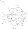
- FIG. 1A a perspective view of the distal portion of a system for diagnosing and/or treating a heart arrhythmia, such as atrial fibrillation and/or ventricular tachycardia, is illustrated.
- the system includes an ablation catheter slidingly received by the shaft of a diagnostic catheter.
- System 10 includes diagnostic catheter 100 which is constructed and arranged for insertion into a body location, such as the chamber of a heart.
- Catheter 100 includes shaft 120, typically constructed of sufficiently flexible material to allow insertion through the tortuosity imposed by the patient's vascular system.
- an expandable assembly 130 which includes a plurality of electrodes 141 coupled thereon.
- System 10 further includes ablation catheter 200, which includes shaft 220.
- Shaft 220 includes at least one ablation element 261, positioned at the tip or otherwise on a distal portion of shaft 220.
- Ablation element 261 is constructed and arranged to deliver energy to tissue, such as when ablation catheter 200 is attached to a source of energy as is described in reference to FIG. 6 herebelow.
- Shaft 120 includes a lumen 126 traveling from at least a proximal portion of shaft 120 (e.g. from a handle, not shown but typically positioned on shaft 120's proximal end) to a distal portion of shaft 120 (e.g. to shaft 120's distal end).
- Shaft 220 of ablation catheter 200 and lumen 126 of diagnostic catheter 100 are constructed and arranged to allow shaft 220 of ablation catheter 200 to be slidingly received by lumen 126.
- Lumen 126 can be further configured to slidingly receive additional catheters or other elongate devices, such as prior to insertion of diagnostic catheter 100 into a body, or after diagnostic catheter 100 has been inserted into a body.
- Diagnostic catheter 100 can be used for mapping tissue such as an organ or portion of an organ (e.g. a portion of a heart wall). Three dimensional anatomical mapping information collected by diagnostic catheter 100 can be used by system 10 to create a three dimensional display of an anatomical location of which at least a portion is to be treated by ablation catheter 200. Diagnostic catheter 100 can be coupled to a computer system, not shown but configured to display anatomical mapping information generated by diagnostic catheter 100 such as volumes, locations, shapes, contours, and movement of organs, nerves, and other tissue within the body. Diagnostic catheter 100 can be coupled to the computer system to display the electrical mapping information generated by diagnostic catheter 100, such as to display dipole mapping or other information as has been described above.
- ablation catheter 200 can be displayed, such as their position relative to tissue or diagnostic catheter 100.
- diagnostic catheter 100 can be used to map the heart, while ablation catheter 200 can be directed to a tissue location in the heart targeted for treatment (e.g. targeted for treatment based on information provided by diagnostic catheter 100).
- ablation catheter 200 can be configured to ablate cardiac tissue to treat a patient suffering from a cardiac arrhythmia, such as atrial fibrillation, atrial flutter, supraventricular tachycardias (SVT), Wolff-Parkinson-White syndrome, and ventricular tachycardias (VT).
- SVT supraventricular tachycardias
- VT ventricular tachycardias
- An ablation catheter will be described herein as a form of a treatment device for purposes of conveying aspects of the invention, but a different type of treatment device (e.g., a pacing device; a defibrillation device; a stent delivery device; a drug delivery device, a stem cell delivery device, or the like) can be used in other embodiments in combination with diagnostic catheter 100.
- a different type of treatment device e.g., a pacing device; a defibrillation device; a stent delivery device; a drug delivery device, a stem cell delivery device, or the like
- diagnostic catheter 100 e.g., a different type of treatment device
- one or more of these treatment devices is inserted through a lumen of diagnostic catheter 100.
- system 10 is configured to access the left atrium of the patient while utilizing a single transseptal puncture through which all the catheter components of system 10 access the left atrium (and subsequently the left ventricle in some cases). In other embodiments, system 10 is configured to access the left ventricle of the patient while utilizing a single crossing of the aortic valve through which all the catheter components of system 10 access the left ventricle (and subsequently the left atrium in some cases).
- System 10 can include sheath 50, for example a standard access sheath, such as a standard transseptal access sheath.
- sheath 50 is inserted through the atrial septum and into the left atrium, followed by the insertion of diagnostic catheter 100 through a lumen of sheath 50. Subsequently, ablation catheter 200 is inserted through lumen 126 of diagnostic catheter 100. In other methods, sheath 50 is inserted into the left atrium, followed by the simultaneous insertion of diagnostic catheter 100 and ablation catheter 200 (e.g. diagnostic catheter 100 is inserted with ablation catheter 200 residing at least partially within lumen 126). In some embodiments, sheath 50 can include a steerable sheath. Shaft 120 comprises a diameter along the majority of its length such as to be slidingly received by sheath 50. In some embodiments, shaft 120 comprises a diameter less than or equal to 15 Fr.
- diagnostic catheter 100 and/or ablation catheter 200 are steerable, such as is described in reference to FIGs. 3 and 6 herebelow, so as manual, semi-automatic or automatic steering can be performed by an operator and/or a robotic control assembly of system 10.
- Diagnostic catheter 100 can be positioned in the left atrium and can provide information selected from the group consisting of: electrical information such as surface charge information; anatomical geometry information such as heart wall surface information or heart wall thickness information; other physiologic and anatomical information such as those described herein; and combinations of these.
- Shaft 120 of diagnostic catheter 100 can be configured to be inserted into the heart via the venous system, for example a vein in a leg or a vein in a neck.
- Shaft 120 can include a braid within its outer and inner surfaces, not shown but typically a braid of plastic or metal fibers that enhance the structural integrity and performance of shaft 120.
- the braid of shaft 120 can include conductors, such as is described in reference to FIG. 3 herebelow.
- diagnostic catheter 100 of FIG. 1A includes lumen 126 extending from a proximal portion to a distal portion of shaft 120, for example from a proximal end to a distal end of shaft 120 so as to allow a separate catheter or other elongate device to be inserted therethrough, such as ablation catheter 200, as shown.
- the inserted catheter or other elongate device can include a diagnostic catheter such as a diagnostic catheter configured to record signals from a location selected from the group consisting of: the left atrium; the right atrium; the Bundle of HIS; the right ventricular apex; a pulmonary vein; the coronary sinus.
- the inserted catheter can comprise another catheter device, such as catheter device 700 described in reference to FIG. 6 herebelow.
- Diagnostic catheter 100 of FIG. 1A includes expandable assembly 130, which is positioned at the distal end of shaft 120.
- expandable assembly 130 includes an array of splines 131, each spline 131 having proximal segment 132, middle portion 134, and distal segment 133.
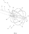
- Proximal segment 132 of each spline 131 connects to shaft 120, via connection point 127, described in detail in reference to FIG. 2 herebelow.
- the distal ends of each spline 131 connect in a circumferential ring configuration to form opening 135.
- Opening 135 allows a device to pass therethrough such as a device inserted into lumen 126, for example shaft 220 of ablation catheter 200.
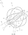
- expandable assembly 130 can include one or more guide elements configured to guide a device through opening 135, guide elements not shown but described in detail in FIGs. 7A-B herebelow.
- Expandable assembly 130 is constructed and arranged to be positioned in the expanded shape shown in FIG. 1A .
- the expanded geometry of assembly 130 including at least two or more splines 131 in an expanded or partially expanded state (hereinafter “expanded state"), can be described as a "basket” having a substantially hollow center and spaces between adjacent splines 131.
- the basket is spherical, but can include any suitable shape, for example an ellipsoid.
- assembly 130 can comprise different shapes or combination of shapes, such as an array of splines 131 where two or more splines 131 comprise similar or dissimilar shapes, dimensions or configurations.
- two or more splines 131 include a varied radius of curvature.
- Expandable assembly 130 can be biased in an expanded or non-expanded state.
- assembly 130 can be self-expanding such that splines 131 are resiliently biased in the curved geometry shown in FIG. 1A .
- Assembly 130 can automatically expand when assembly 130 exits the distal end of sheath 50, such as by advancement of shaft 120 and/or retraction of sheath 50.
- assembly 130 can be manually expanded, for example via retraction of a rod 129 that slides within shaft 120 and is connected to distal end of assembly 130, as described in detail in reference to FIG. 2 herebelow.
- Splines 131 can be constructed of a material selected from the group consisting of: one or more thermoplastic polymers such as polyether block amide, polyurethane and/or polyether ether ketone; one or more of thermoset polymers such as silicon and/or tetrafluoroethylene; one or more metals such as stainless steel and/or shaped memory alloys such as nickel titanium alloy; one or more shape memory polymers such as triple shape acrylic; and combinations of these.
- thermoplastic polymers such as polyether block amide, polyurethane and/or polyether ether ketone
- thermoset polymers such as silicon and/or tetrafluoroethylene
- metals such as stainless steel and/or shaped memory alloys such as nickel titanium alloy
- shape memory polymers such as triple shape acrylic
- Splines 131 can include one or more electrodes 141 and/or one or more ultrasound transducers 151 arranged in any combination.
- each spline 131 includes at least four, six or eight electrodes 141; each spline 131 includes at least four, six or eight ultrasound transducers 151; and combinations of these.
- at least one electrode 141 is positioned between two ultrasound transducers 151 on a single spline 131.
- at least two electrodes 141 are positioned between two ultrasound transducers 151 on a single spline 131.
- Each spline 131 can include a similar or dissimilar arrangement of electrodes 141 and/or ultrasound transducers 151 as an adjacent spline 131 or any other spline 131 in assembly 130.
- assembly 130 includes eight splines 131, where each spline 131 can include two to eight electrodes 141 and two to eight ultrasound transducers 151.
- assembly 130 includes six splines 131, where each spline 131 can include eight electrodes 141 and eight ultrasound transducers 151.
- one or more splines 131 include a number of electrodes 141 that comprises a quantity within one of the quantity of ultrasound transducers 151 that are included on that spline 131.
- a spline 131 can include seven electrodes 141 and either six or eight ultrasound transducers 151.
- a set of electrodes 141 and ultrasound transducers 151 can be arranged in an alternating arrangement, such that one or more single ultrasound transducers 151 lies between two electrodes 141.
- some sets of electrodes 141 and ultrasound transducers 151 can be arranged such that one or more single electrodes 141 is positioned between two ultrasound transducers 151.
- Electrodes 141 can be configured to record electric signals such as voltage and/or current signals.
- System 10 can utilize the recorded signals to produce electrogram information; dipole mapping information; distance information such as the distance between any device and/or component of system 10; and other information or combinations of information described in detail herein.
- Any or all electrodes 141 of system 10 can comprise a dipole mapping electrode, such as an electrode with a impedance or other electrical property configured to provide information related to surface charge or other dipole mapping parameter.
- the electrodes 141 are of sufficiently low impedance, such as in the range less than 10,000 ohms, such as to achieve high-fidelity recording of signal frequencies greater than or equal to 0.1 Hz.
- one or more electrodes 141 include an iridium oxide coating, such as to reduce the impedance of electrodes 141. Alternatively or additionally, numerous forms of coatings or other treatments can be included with one or more electrodes 141, such as a platinum black coating or a carbon nanotube layer. In addition or as an alternative to recording electric signals, electrodes 141 can be constructed and arranged to deliver electric energy, such as radiofrequency energy. In some embodiments, diagnostic catheter 100 can deliver therapy, such as an ablation therapy delivered to tissue, in addition to its function as a diagnostic catheter, e.g. providing electrical, anatomical and/or device mapping information. In some embodiments, one or more electrodes 141 each comprise one or more coils, such as when the one or more coils are configured to create one or more magnetic fields.
- Electrodes 141 can include various materials such as non-polarizing metals and/or polarizing metals.
- one or more electrodes 141 comprise at least one non-noble metal such that electrodes 141 oxidize when in contact with at least one of blood, blood plasma or saline solutions.
- electrodes 141 include a coating, for example a coating selected from the group consisting of: a metal oxide coating; a conductive polymer coating; and combinations of these.
- one or more electrodes 141 can include an outer layer and an inner layer, such as when the outer layer comprises an impedance lowering coating or other layer and the inner layer comprises a layer configured to bond the outer layer to the metallic and/or other remaining portion of the one or more electrodes 141.
- Ultrasound transducers 151 can be configured to record distance information such as the distance between any device and/or component of system 10 and tissue such as cardiac wall or other solid tissue.
- Ultrasound transducers 151 can include a construction comprising: single or multi-element piezoelectric ceramics; piezoelectric micro-machined ultrasound transducers (pMUT); capacitive micro-machined ultrasound transducers (cMUT); piezoelectric polymers; and combinations of these.
- diagnostic catheter 100 can include a multilayer or laminate construction, for example where shaft 120 includes a tube inside of another tube; where shaft 120 includes a liner such as a lubricous liner such as PTFE; where shaft 120 includes a braided construction such as a braid positioned between two layers of shaft 120; and combinations of these.
- diagnostic catheter 100 can be steerable, for example via the incorporation of a pull wire and anchor as shown and described in reference to FIG. 3 herebelow.
- diagnostic catheter shaft 120 outer diameter is less than 15 Fr.
- Ablation catheter 200 of FIG. 1A includes ablation element 261 positioned on shaft 220, for example on a distal portion or the distal tip of shaft 220.
- Ablation element 261 can include a functional element selected from the group consisting of: one or more electrodes; a vessel configured to deliver cryogenic energy; a laser diode; an optical fiber configured to deliver ablative energy; a microwave energy delivery element; an ultrasound energy delivery element; a drug, stem cell, or other agent delivery element; a mechanical or other ablation device delivery element; and combinations of these.
- the electrodes can include electrodes constructed and arranged to deliver radiofrequency (RF) energy.
- RF radiofrequency
- ablation element 261 includes an array of elements such as in one or more of the component array configurations shown in FIG. 6 .
- Ablation catheter 200 can be operably connected to a device configured to deliver energy to ablation element 261, such as energy delivery unit 400 of FIG. 6 .
- Typical energy delivered by ablation element 261 comprises an energy selected from the group consisting of: electromagnetic energy such as radiofrequency energy; cryogenic energy; laser energy; light energy; microwave energy; ultrasound energy; chemical energy; and combinations of these.
- ablation catheter 200 can be steerable, such as via a pull wire and anchor as described in reference to FIG. 3 herebelow.
- distal portion 225 of ablation catheter 200 has been steered in the curved geometry shown to cause ablation element 261 to exit expandable assembly 130 of diagnostic catheter 100, passing between two middle portions 134 of two splines 131.
- Ablation catheter 200 can be steered and advanced by an operator such as a clinician, so as to exit at any opening of the expandable assembly 130, including the space between two splines 131 or through opening 135, such as to be further advanced to contact and ablate cardiac tissue.
- System 10 includes diagnostic catheter 100 and ablation catheter 200.
- Diagnostic catheter 100 comprises an elongate shaft 120 which includes lumen 126 exiting its distal end.
- Ablation catheter 200 which has been removed for clarity, is configured to be slidingly received by lumen 126.
- Diagnostic catheter 100 includes push rod 129, typically a solid tube or hypotube slidingly received within a wall or a lumen of shaft 120, that can be used to expand or collapse (i.e. un-expand or compact) expandable assembly 130.
- Push rod 129 can be operably attached to a handle, not shown but typically a handle including one or more controls used to advance or retract push rod 129 and/or steer one or more catheter shafts.
- retracting rod 129 causes assembly 130 to expand (e.g. the backward force applied on the distal end of assembly 130 by rod 129 causes splines 131 to bow), and advancing rod 129 causes assembly 130 to collapse (e.g. the forward force applied on the distal end of assembly 130 by rod 129 causes splines 131 to straighten).
- expandable assembly 130 includes an array of splines 131, each spline 131 having proximal segment 132, middle portion 134 and distal segment 133.
- Distal segments 133 of each spline 131 connect in a circumferential ring configuration to form opening 135, which is relatively orthogonal to and relatively centrally positioned about axis "A", which comprises the central axis of the distal portion of shaft 120.
- Opening 135 allows the distal portion of a shaft of a device to pass therethrough, such as a device inserted into lumen 126, for example shaft 220 of ablation catheter 200 of FIGs. 1A and 1B .
- Proximal segment 132 of each spline 131 connects to shaft 120 via connection points 127.
- a mechanical attachment can be made between any spline 131 and shaft 120 at connection points 127, such as an attachment comprising a compression fitting or adhesive.
- Any spline 131 can be attached to shaft 120 at connection point 127 via a bonding process, such as a thermal bonding process where a spline 131 is positioned in the wall of shaft 120 or when shaft 120 comprises two polymer coaxial tubes and spline 131 is thermally set between the tubes.
- adhesive bonds, mechanical crimps or and/or other bonds can be used.
- Proximal segments 132 are convex with respect to central axis "A" of the distal portion of shaft 120.
- Proximal segments 132 can transition to middle portions 134 through an inflection point, such that middle portions 134 and distal segments 133 are concave with respect to axis "A".
- the radius of curvature of proximal segment 132 ranges from approximately 0.01mm to 25 mm, or larger.
- proximal segments 132 can be chosen to allow smooth capture of assembly 130 by sheath 50, avoiding any undesired threshold forces required to initiate the radial compression of assembly 130.
- Other configurations for proximal segments 132 can be used to facilitate a smooth transition from the expanded state to the unexpanded, captured state.
- push rod 129 can be partially advanced, such as to partially collapse expandable assembly 130, initiating radial compression of assembly 130, thus facilitating an easier capture of splines 131 by sheath 50.
- diagnostic catheter 100 includes an equal number of ultrasound transducers 151 and electrodes 141, such as an array comprising forty-eight ultrasound transducers 151 and forty-eight electrodes 141.
- relative positions of splines 131, electrodes 141, and ultrasound transducers 151 of expandable assembly 130 are of known values, such as when expandable assembly 130 is in a pre-configured "biased" state (e.g. a resiliently biased, fully expanded state with no forces applied). These known values can be correlated to a 3D coordinate system, such as a Cartesian coordinate system; a spherical coordinate system; and/or a coordinate system with an origin at the center of the expandable array or any location.
- the origin of a coordinate system can be used to map the location of one or more of: one or more components of diagnostic catheter 100 such as one or more splines 131, one or more electrodes 141 or one or more ultrasound transducers 151; one or more components of ablation catheter 200 of FIGs. 1A and 1B such as ablation element 261; one or more components of a separate device inserted into the patient; one or more components of a separate device external to the patient; one or more portions of the patient's anatomy.
- diagnostic catheter 100 such as one or more splines 131, one or more electrodes 141 or one or more ultrasound transducers 151
- ablation catheter 200 of FIGs. 1A and 1B such as ablation element 261
- one or more components of a separate device inserted into the patient one or more components of a separate device external to the patient
- one or more portions of the patient's anatomy can be used to map the location of one or more of: one or more components of diagnostic catheter 100 such as one or more splines 131,
- diagnostic catheter 100 can be located at a useful position for performing a medical procedure, such as at the distal end of shaft 120, the distal tip of expandable assembly 130, the geometric center of expandable assembly 130, any electrode 141 or ultrasound transducer 151, or any other useful location.
- diagnostic catheter 100 utilizes three or more electrodes 141 (e.g. any three electrodes 141) as a reference.
- the three or more electrodes 141 can be used to triangulate the position of a marker electrode, such as an electrode on a separate device and positioned proximate expandable assembly 130.
- Each of the reference electrodes can be configured to emit an electric signal, with the three signals comprising three similar waveforms with the exception of a phase shift of 120° between them.
- a marker electrode can record a combined summation of the three phase shifted signals. This combined signal can be used (e.g. by one or more components of a system such as system 10 of FIG.
- the marker electrode determines the position of the marker electrode in relation to the three electrodes, such as by using one or more triangulation algorithms. For example, if the marker electrode is at a geometric center of the three electrodes, the resultant electric signal will be zero. Non-zero readings are analyzed to determine the distance from each reference electrode to the marker electrode. Precision of marker electrode position can be improved by having additional electrodes 141 (e.g. four or more) emit a signal to be recorded by the marker electrode with values to be processed by a positioning algorithm.
- additional electrodes 141 e.g. four or more
- three or more reference electrodes emit an electric signal, such as an electric signal provided by a component of a system, such as system 10 of FIG. 6 described herebelow.
- Such reference electrodes can be located in various locations, such as a location selected from the group consisting of: on diagnostic catheter 100; on an ablation catheter such as ablation catheter 200 of FIGs. 1 and 6 described herein; on one or more separate devices, such as one or more separate devices proximate expandable assembly 130; on one or more locations on the surface of the body; and combinations of these.
- Each reference electrode can sequentially emit a signal at the same frequency or simultaneously emit signals at different frequencies.
- Three or more marker electrodes record signals with values that differ in logarithmic-proportion to the separation distance between the reference electrodes and the marker electrodes.
- a set of three or more such marker electrodes can be comprised of any electrode 141 located on diagnostic catheter 100 or any two or more of any electrodes 141 located on diagnostic catheter 100 in combination with any one or more electrodes located on one or more separate devices positioned proximate expandable assembly 130. Recorded differences in signal-values by the marker electrodes can be combined to determine the position of the marker electrodes in relation to the reference electrodes, such as by using one or more triangulation algorithms. For example, if two or more marker electrodes are equidistant from any reference electrode, the corresponding recorded signal-values on each marker electrode will be equal in magnitude.
- the values of the recorded signals will be unequal to each other in logarithmic-proportion to the amount by which each marker-electrode-to-reference-electrode separation distances are unequal.
- the volume of the polyhedron can be analyzed to triangulate the position of the marker electrodes. Precision of the marker electrode positions can be improved by having additional neighboring sets of reference and marker electrodes that emit and record signals, respectively, and by similarly analyzing the associated sets of polyhedral volumes and combining the results of triangulation.
- an electric signal is delivered between two reference electrodes (i.e. emitted from a first electrode and "returned” to a second electrode), such as by a component of system, such as system 10 of FIG. 6 described herebelow.
- Such reference electrodes are comprised of any two of electrodes 141 located on diagnostic catheter 100 or any one of electrodes 141 located on diagnostic catheter 100 in combination with any electrode located on any separate device positioned proximate expandable assembly 130 or on any electrode located on the body surface.
- Three or more marker electrodes located between and proximate the two reference electrodes record signals with values that differ in logarithmic-proportion to the separation distance between each of the two reference electrodes and the marker electrodes.
- Any three or more such marker electrodes are comprised of any electrode 141 located on diagnostic catheter 100 or any two or more of any electrode 141 located on diagnostic catheter 100 in combination with any one or more electrodes located on one or more separate devices positioned proximate expandable assembly 130. Recorded differences in signal values can be combined to determine the position of the marker electrodes in relation to the resultant electric field generated by the signal delivered between the two reference electrodes.
- One or more geometric shape algorithms can be used for which the recorded signal values comprise shape parameters that conform to the geometric shape of the resultant electric field between and proximate all of the marker electrodes (e.g.
- Precision of the marker electrode determined positions can be improved by increasing the number of marker electrodes that are used to parameterize the shape of the resultant electric field and/or by using additional unique neighboring pairs of reference electrodes to generate the resultant electric field across unique spans of the 3D space between and proximate the marker electrodes.
- the resultant marker field-values are recorded, the associated sets of resultant electric field shapes are parameterized, and the parameters are combined into a common resultant shape. Signals of one frequency are applied sequentially between multiple reference electrode-pairs and signals with different frequencies can be applied simultaneously.
- one or more marker electrodes can comprise an ablation element (e.g. to deliver RF energy), or it can be at a known position relative to an ablation element or other component of a device of a system, such as system 10 of FIG. 6 described herebelow.
- ablation element e.g. to deliver RF energy
- Spline 131 is positioned proximate tissue ("TISSUE") and includes ultrasound transducers 151a and 151b as shown.
- Spline 131 further includes electrodes 141a, 141b, 141c and 141d as shown.
- Ultrasound transducers 151a, 151b can be used to provide distance information, such as the distance between each ultrasound transducer 151a, 151b and TISSUE.
- This distance information can be used to determine the distance between one or more electrodes 141a, 141b, 141c, 141d and TISSUE, for example by using the known distance between one or more electrodes 141a, 141b, 141c, 141d and one or more ultrasound transducers 151a, 151b, as well as a known or measured shape of spline 131, That is, the distance between any ultrasound transducer and any electrode (e.g. d1 or d1' as shown) is known or can be calculated by the system of the present invention (e.g. a calculation to account for distance changes due to bending of splines 131).
- a distance between any ultrasound transducer and TISSUE can be determined according to traditional ultrasound algorithms, for example the distances between ultrasound transducer 151a and 151b and TISSUE, represented by d2 and d2', respectively.
- a distance between any electrode and TISSUE can be calculated, for example the distance between electrodes 141a, 141b, 141c and 141d and TISSUE, represented by d3, d3', d3", and d3''', respectively.
- any spline 131 can change shape. Alternatively or additionally, an imparted force on any spline 131 can cause that spline 131 to move in relation to another spline 131.
- Systems of the present invention can be constructed and arranged to measure these geometric changes to one or more splines 131.
- electrical information can be collected by one or more electrodes 141 to measure one or more distances, and one or more algorithms of system 10 use the one or more measured distances - to determine a geometric configuration of one or more splines 131.
- a current is applied between any two electrodes 141, and the distance between the two electrodes 141 can be determined, such as with one or more algorithms to determine a distance, as is described in detail in reference to FIG. 2A hereabove.
- Distance information can be used by one or more algorithms of system 10 to derive the real-time shape or relative positioning of one or more splines 131.
- the shape of a spline 131 and the distance between two electrodes 141 positioned on spline 131 is known, when spline 131 is in an equilibrium (e.g. resiliently biased) state.
- Measurement of a change to the equilibrium separation distance between two electrodes 141 positioned on a single spline 131 can be used by an algorithm of system 10 to determine the change in shape to the spline 131 as one or more forces are applied (e.g. as a spline 131 is pressed against a heart wall).
- increased bowing of a spline 131 can cause the electrode 141 separation distance to decrease, and straightening of a spline 131 can cause the electrode 141 separation distance to increase, each in a predictable manner.
- the distance between a first electrode 141 on a first spline 131 and second electrode 141 on a second spline 131 is also known. Measurement of a change in the separation distance between these two electrodes 141 positioned on two splines 131 can be used to determine a change in relative positioning of the two splines 131 as one or more forces are applied (e.g. as a spline 131 is pressed against a heart wall).
- the distance between any two electrodes positioned on any two separate devices can be determined by an algorithm of system 10, such as the distance between one or more portions of diagnostic catheter 100 and one or more portions of ablation catheter 200, each described in reference to FIGs. 1 and 6 .
- Another algorithm of system 10 can include measuring the distance between an electrode positioned on diagnostic catheter 100 and an electrode positioned on a third catheter device such as catheters 500 and 600 described in FIG. 6 herebelow. This measurement can be repeated between any two electrodes positioned on any device, at any time during the clinical procedure.
- This distance information can be useful to determine the geometry of an expandable assembly, such as expandable assembly 130 described herein, when the known expanded geometry has changed, for example when a force is exerted by a tissue wall on assembly 130.
- System 10 can include one or more algorithms that use distance information data to localize, or allow an operator to localize, one or more devices of system 10. Alternatively or additionally, system 10 can include one or more algorithms that use distance information data to navigate, or allow an operator to navigate, one or more devices of system 10.
- the localization and/or navigation can comprise real-time or near real-time localization and/or navigation.
- the signals applied to any of the electrodes of system 10 can include constant or variable currents and/or voltages and/or other processed values.
- FIG. 3 a side view of a distal portion of the system of FIG. 1A is illustrated, where the diagnostic catheter has been retracted into the sheath.
- Diagnostic catheter 100 has been retracted into sheath 50 such that splines 131 and other components of expandable assembly 130 are in a collapsed or unexpanded state.
- Ablation catheter 200 has been slightly retracted into shaft 120 of diagnostic catheter 100 such that ablative element 261 remains partially exposed. Retraction of diagnostic catheter 100 and/or ablation catheter 200 can be performed by an operator grasping the relevant proximal portion (e.g. a handle) and moving the device proximally relative to sheath 50.
- the relevant proximal portion e.g. a handle
- Shaft 120 of diagnostic catheter 100 can include braid 121.
- braid 121 is positioned between an inner layer and an outer layer of shaft 120.
- Portions or all of braid 121 can include conductors, for example a helical or other arrangement of conductors integral to, positioned within and/or passing through braid 121 and operably connected to electrodes 141 and/or ultrasound transducers 151.
- conductor 125 connects to wire 142 at connection point 143 (e.g. a solder connection point that operably connects to electrode 141).
- conductor 124 connects to wire 152 at connection point 153 (e.g. a solder connection point that operably connects to ultrasound transducer 151).
- conductors 124 and/or 125 include a standard wire with an insulation covering.
- conductors 124 and/or 125 include a coaxial cable, such as a coaxial cable with a diameter of approximately less than 0.012 inches.
- conductors 124 and/or 125 are not part of braid 121, but rather pass through braid 121 and/or pass along an inner or outer surface of braid 121.
- sheath 50 includes pull wire 52 and anchor 53 which can be connected to a lever, a cam, or other wire control mechanism which is operably connected to a knob or slide positioned on a handle, all not shown but located at a proximal end of sheath 50.
- diagnostic catheter 100 includes pull wire 122 and anchor 123
- ablation catheter 200 includes pull wire 222 and anchor 223, each pull wire 122 and 222 typically controlled as described above by a control on a handle.
- Each device can be independently controlled via its respective steering pull wire and anchor, however if desired two or more devices can be controlled in concert, such as via a single control.
- Each device can comprise multiple pull wires, not shown but configured to provide multiple degrees of steering freedom.
- a diagnostic catheter is inserted into a heart chamber, for example the left atrium, the right atrium, the left ventricle, or the right ventricle.
- the diagnostic catheter can be the same as or similar to diagnostic catheter 100 described herein.
- the diagnostic catheter can be inserted through previously inserted transseptal sheath, for example sheath 50 described herein.
- the diagnostic catheter includes one or more distance measurement elements, such as ultrasound transducers 151 described herein.
- a treatment device such as ablation catheter 200 can also be inserted into a heart chamber, either simultaneously with the diagnostic catheter (e.g.
- the ablation catheter shaft when the ablation catheter shaft resides within a lumen of the diagnostic catheter), or it can be inserted subsequent to the insertion of the diagnostic catheter, for example at a time after a 3-D map of the heart chamber has been created.
- the treatment device can be inserted through a lumen of the diagnostic catheter so that only a single transseptal puncture is required, as has been described in reference to FIG. 1A hereabove.
- a first set of surface data is collected via one or more ultrasound transducers positioned on the diagnostic catheter such as ultrasound transducers 151 described herein.
- surface data can be collected from ultrasound transducers positioned on a separate device such as device 200, 500, 600, 700 and/or an external device such as an external ultrasound device or other accessory device such as device 800 of FIG. 6 .
- Data collected from the ultrasound transducers of device 100, 200, 500, 600, 700, and/or 800 can include distance information such as the distance from any ultrasound transducer to tissue such as cardiac tissue.
- electrical information can also be collected via one or more electrodes positioned on a device, such as electrodes 141 described herein, or one or more electrodes positioned on one or more devices such as devices 100, 200, 500, 600 and/or 700 described herein.
- the electrical information can be used to determine distances between devices or device components, and it can be used to determine a geometric change in a device that occurs when a force is imparted, such as by using the algorithms described in reference to FIG. 2B hereabove.
- the electrical information can be collected simultaneously or synchronously with the data collected from the ultrasound transducers.
- data is collected during multiple heart cycles where sequential sets of data can be correlated to a particular point in the heart cycle, for example data sets that are coordinated with a surface ECG recording that is simultaneously collected.
- the diagnostic catheter and/or any device including ultrasound transducers and/or electrodes is repositioned within the heart chamber so that a next set of surface data can be collected, similar to the collection of data in STEP 904.
- any or all sets of collected surface data are combined via a signal processing unit, for example signal processing unit 300 of FIG. 6 .
- Multiple sets of ultrasound distances can be combined to generate a point cloud of surface points.
- a high-resolution reconstruction of the chamber surface can be "meshed" across the point cloud and displayed as an anatomical three-dimensional model.
- the relative position of the array is localized through time so that all subsequent acquired distances are translated back to a universal origin in the coordinate system and thereby combined into a single set of surface points.
- the distances from the surface to any element and the voltage reading of that element can be used to calculate charge source values with respect to time.
- the charge source values; unipolar voltage or bipolar voltage values; monophasic action potential values; or other processed physiologic parameters; and combinations of these, can then be displayed upon the surface reconstruction.
- the signal processing unit can include an algorithm to determine or to assist in determining if the combined data is sufficient for display.
- This step can be a manual step, for example where a clinician can determine if the data is sufficient based on one or more outputs provided by the signal processing unit.
- this can be an automated step, for example where a threshold algorithm of the signal processing unit determines if the data points are within a particular range of values, or if the amount of collected data points meet a minimum number of sufficient data points. If the data points are determined to be insufficient, the method repeats beginning at STEP 906 where a next set of data is collected.
- the method proceeds to STEP 912 where a 3-D map is displayed.
- the surface data collected from the ultrasound transducers or other transducers can be used to create an anatomical map of the heart chamber, and the surface data collected from the electrodes or other sensors can be used to create an electrical map of the heart chamber.
- the anatomical and electrical maps can be superimposed on one another.
- an algorithm can be employed to create a dipole density map. Details related to an applicable algorithm is disclosed in Applicant's co-pending international application, Serial Number PCT/US2012/028593 , entitled Device and Method For the Geometric Determination of Electrical Dipole Densities on the Cardiac Wall, the entirety of which is incorporated herein.
- the anatomical and electrical maps can be overlaid to create a comprehensive 3-D map of the heart chamber.
- the data can represent a sequential set of data points corresponding to the beating cycle of the heart and associated heart wall motion (e.g. the repeated cycles of systole and diastole).
- All data can be stored in memory by the signal processing unit or another component of the system of the present invention, such as for further processing, playback, or any other desired presentation or analysis.
- FIG. 5 a flow chart of a method for localizing an ablation catheter within a body using the system of the present invention is illustrated.
- STEP 922 a 3-D electrical and/or anatomical map of a heart chamber is created, for example via the method disclosed in FIG. 4 .
- an ablation catheter is positioned within the mapped heart chamber.
- the ablation catheter can be the same as or similar to ablation catheter 200 and/or 600 described herein.
- the ablation catheter can be inserted in a lumen of a diagnostic catheter, for example diagnostic catheter 100 as has been described herein.
- the ablation catheter is located, such as a location in relation to the patient's anatomy and/or another device of the system of the present invention.
- An ablation catheter such as catheter 200 or 600 of FIG. 6 can be located using a triangulation technique, such as that described in reference to FIG. 2 hereabove.
- the triangulation technique can utilize recorded signals from multiple electrodes positioned in an expandable assembly, such as expandable assembly 130 described herein, and one or more energy delivery elements, such as electrodes 241 or 641 of catheters 200 or 600, respectively, of FIG. 6 .
- the ablation catheter is steered to target tissue under guidance, such as while being navigated by the system of the present invention using the triangulation techniques described herein. Detail related to an applicable steering mechanism is described in detail in reference to FIG. 3 hereabove.
- the triangulation technique of FIG. 2A is repeated continuously or semi-continuously, such as to provide a feedback loop used by an operator to steer the catheter.
- a feedback loop can include robotic or other automatic guidance of a catheter, for example a computer system, such as signal processing unit 300 of FIG. 6 , can control steering, advancement and/or retraction of one or more catheters, such as via steering and linear motion assemblies in the handle of the catheter.
- visual feedback can be provided to an operator, such that the operator can perform manual steering, advancement and retraction of one or more catheters, while being provided catheter position information.
- the ablation catheter includes an ablation element that can include one or more electrodes; an energy delivery element configured to deliver cryogenic energy such as a cryogenic balloon; a laser delivery element such as a laser diode; an optical fiber configured to deliver ablative energy; a microwave energy delivery element; an ultrasound energy delivery element; a drug or other agent delivery element; and combinations of these.
- the ablation element can include radiofrequency electrodes.
- the electrodes can be configured for bipolar and/or monopolar energy delivery.
- the ablation element includes an array of elements such as in catheter 600 of FIG. 6 . Further, the ablation catheter can be operably connected to an energy delivery unit, such as energy delivery unit 400 of FIG. 6 .
- STEPs 928 and 930 can be repeated one or more times, such as until the treatment is complete or otherwise ceased.
- System 10 includes diagnostic catheter 100 and can also include sheath 50, ablation catheter 200, second diagnostic catheter 500, second ablation catheter 600, and/or accessory catheter device 700, each described in turn with reference to this figure.
- System 10 includes signal processing unit (SPU) 300, such as a computer system used to receive signals to produce electrical, anatomical and/or device mapping information.
- System 10 can include energy delivery unit (EDU) 400, such as an electrical or other energy delivery system that provides energy to one or more ablation elements of system 10, as are described herebelow.
- System 10 can include an accessory device 800, such as an imaging device comprising an externally applied ultrasound probe.
- System 10 can include one or more visual displays, such as one or more visual displays integral to SPU 300, EDU 400 or another device or component of system 10.
- the various components of system 10 can be electrically and/or mechanically connected by one or more cables, such as cables including electric wires and/or optical fibers to transmit data and/or power.
- SPU 300, EDU 400 and/or robotic control assembly 850 transfer information to or from each other, such as via the wired or wireless communication pathways shown in Fig. 6 .
- Diagnostic catheter 100 includes expandable assembly 130 positioned at the distal end of shaft 120.
- Expandable assembly 130 can be resiliently biased in the radially expanded position shown in FIG. 6 or it can include a means of manual expansion, such as has been described hereabove.
- Expandable assembly 130 includes multiple splines 131, such as splines 131a and 131b shown. The distal ends of splines 131 can be configured in a ring-shaped geometry, opening 135, such as is described in reference to FIG. 1A hereabove.
- Expandable assembly 130 includes electrodes 141a and 141b and ultrasound transducers 151a and 151b, having the same or similar functionality as electrodes 141 and ultrasound transducers 151 described in FIG. 1A .
- Diagnostic catheter 100 typically includes four or more electrodes 141, such as an array of two to ten splines 131 where each spline 131 including four to ten electrodes 141. Diagnostic catheter 100 typically includes four or more ultrasound transducers 151, such as an array of two to ten splines 131 each spline 131 including four to ten ultrasound transducers 151. Diagnostic catheter 100 includes shaft 120 having a lumen configured to slidingly receive the shaft of a separate catheter, such as shaft 220 of ablation catheter 200. Handle 110, located at the proximal end of shaft 120, includes pigtail 113 where one or more shafts, simultaneously or sequentially, can be inserted to enter lumen 126 and to exit the distal end of shaft 120.
- Diagnostic catheter 100 can be inserted into a heart chamber, for example via a transseptal sheath, such as sheath 50.
- Handle 110 can include one or more controls, such as control 115.
- Control 115 can be constructed and arranged to allow an operator to perform an action selected from the group consisting of: steer shaft 120; radially expand assembly 130; radially contract assembly 130; and combinations of these.
- Control 115 can be operably connected to a mechanism within handle 110, mechanism not shown but typically a mechanism selected from the group consisting of: a control cable motion assembly such as a control cable motion assembly connected to a steering pull wire as described herein; a linear motion assembly constructed and arranged to advance and/or retract a control rod such as a control rod attached to assembly 130 to expand and/or retract assembly 130 as described herein; and combinations of these.
- a control cable motion assembly such as a control cable motion assembly connected to a steering pull wire as described herein
- a linear motion assembly constructed and arranged to advance and/or retract a control rod such as a control rod attached to assembly 130 to expand and/or retract assembly 130 as described herein; and combinations of these.
- System 10 can include first ablation catheter 200 having a similar construction to ablation catheter 200 of FIG. 1A .
- Ablation catheter 200 includes handle 210 at the proximal end of shaft 220 and ablation element 261 at the distal end of shaft 220.
- Ablation element 261 can include an electrode that is configured to receive one or more forms of energy.
- Ablation catheter 200 can include one or more electrodes 241 and one or more ultrasound transducers 251, having the same or similar functionality as electrodes 141 and ultrasound transducers 151 described in reference to FIG. 1A hereabove, such as to provide anatomical, electrical and/or device mapping information to SPU 300 and/or another component of system 10.
- Handle 210 can include one or more controls such as control 215.
- Control 215 can be constructed and arranged to allow an operator to perform an action selected from the group consisting of: steer shaft 220; activate energy delivery by ablation element 261; adjust ablation delivery by ablation element 261; control an electrical connection to electrode 241 and/or ultrasound transducer 251; and combinations of these.
- Control 215 can be operably connected to a mechanism within handle 210, mechanism not shown but typically a mechanism selected from the group consisting of: a control cable motion assembly such as a control cable motion assembly connected to a steering pull wire as described herein; a linear motion assembly constructed and arranged to advance and/or retract a control rod; an electric switch; and combinations of these.
- System 10 can include second diagnostic catheter 500 having handle 510 at the proximal end of shaft 520 and array 530 at the distal end of shaft 520.
- Array 530 can include recording electrodes 591 configured to record electrical activity.
- array 530 can include electrodes 591 arranged in a spiral array so as to be placed in the coronary sinus or a pulmonary vein, such as to record electrical activity therein.
- Diagnostic catheter 500 can include one or more electrodes 541 and one or more ultrasound transducers 551, having the same or similar functionality as electrodes 141 and ultrasound transducers 151 described in reference to FIG. 1A hereabove, such as to provide anatomical, electrical and/or device mapping information to SPU 300 and/or another component of system 10.
- Handle 510 can include one or more controls such as control 515.
- Control 515 can be constructed and arranged to allow an operator to perform an action selected from the group consisting of: steer shaft 520; radially expand and/or contract array 530; control an electrical connection to electrodes 591, electrode 541 and/or ultrasound transducer 551; and combinations of these.
- Control 515 can be operably connected to a mechanism within handle 510, mechanism not shown but typically a mechanism selected from the group consisting of: a control cable motion assembly such as a control cable motion assembly connected to a steering pull wire as described herein; a linear motion assembly constructed and arranged to advance and/or retract a control rod; an electric switch; and combinations of these.
- System 10 can include second ablation catheter 600 having handle 610 at the proximal end of shaft 620 and array 630 at the distal end of shaft 620.
- Array 630 can include electrodes 691 configured to record electrical activity.
- array 630 can include electrodes 691 arranged in a linear or a two-dimensional array.
- Ablation catheter 600 can include one or more electrodes 641 and one or more ultrasound transducers 651, having the same or similar functionality as electrodes 141 and ultrasound transducers 151 described in reference to FIG. 1A hereabove, such as to provide anatomical, electrical and/or device mapping information to SPU 300 and/or another component of system 10.
- Handle 610 can include one or more controls such as control 615.
- Control 615 can be constructed and arranged to allow an operator to perform an action selected from the group consisting of: steer shaft 620; radially expand and/or contract expandable assembly 630; activate energy delivery by electrodes 691; adjust energy delivery by electrodes 691; control an electrical connection to electrode 641 and/or ultrasound transducer 651; and combinations of these.
- Control 615 can be operably connected to a mechanism within handle 610, mechanism not shown but typically a mechanism selected from the group consisting of: a control cable motion assembly such as a control cable motion assembly connected to a steering pull wire as described herein; a linear motion assembly constructed and arranged to advance and/or retract a control rod; an electric switch; and combinations of these.
- System 10 can include EDU 400 configured to deliver energy to any or all of the catheters and/or devices of system 10, for example catheters 100, 200, 500, 600, and 700 via wires 112, 212, 512, 612, and 712, respectively.
- Typical energy types include but are not limited to: radiofrequency energy; cryogenic energy; laser energy; light energy; microwave energy; ultrasound energy; chemical energy; and combinations of these.
- EDU 400 delivers energy to ablation element 261 of ablation catheter 200.
- EDU 400 can provide ablation energy to any ablation element of system 10, such as electrodes 691 of ablation catheter 600.
- System 10 can include grounding pad 420, shown attached to the back of the patient P, such that EDU 400 can deliver monopolar radiofrequency energy, such as via treatment elements 261, electrodes 691, or any electrode-based ablation element of system 10.
- EDU 400 can be configured to deliver bipolar and/or unipolar radiofrequency energy between any two electrodes in relative proximity to each other, such as two electrodes 691 of ablation catheter 600.
- System 10 includes SPU 300 configured to send and/or record signals to and/or from any or all of the catheters and/or devices of system 10, for example catheters 100, 200, 500, 600, and 700 via wires 111, 211, 511, 611, and 711, respectively.
- SPU 300 can send and/or record signals to and/or from accessory device 800 and/or body surface electrodes 820, such as when body surface electrodes 820 are positioned on the chest and abdomen of patient P as shown.
- SPU 300 can record electric signals such as ultrasonic reflections from any or all of the ultrasound transducers of system 10 and can record current and/or voltage signals from any or all of the electrodes of system 10.
- the ultrasound transducers can be included on any or all of the catheters and/or other devices of system 10 (e.g. any of transducers 151a, 151b, 251, 551, 651, and 751).
- the recording electrodes can be included on any or all of the catheters and/or other devices of system 10 (e.g. any of electrodes 141a, 141b, 241, 541, 641, and 741).
- SPU 300 can perform one or more algorithmic functions and other mathematical calculations on data extracted from the recorded signals. These calculations can result in output selected from the group consisting of: distance measurements; anatomical maps; device position maps; electrical maps; dipole maps; and combinations of these, such as are described in reference to FIG. 4 hereabove.
- SPU 300 can provide catheter guidance or other device position information, such as is described in reference to FIG. 5 hereabove.
- SPU 300 can include a electrical signal source such as a current source that can be coupled to electrodes 141a and 141b of diagnostic catheter 100, for example to collect data to create a dipole density map and/or to perform distance measurements as has been described in detail in reference to FIGs. 2A and 2B hereabove.
- SPU 300 and/or other components of system 10 can be configured as a distance measurement assembly, such as to produce distance measurement data as is described in reference to FIGs. 2A and 2B hereabove.
- System 10 can be configured to produce distance measurement data between any two or more locations selected from the group consisting of: a location of a body inserted component or assembly of system 10 such as a location of a system 10 electrode such as an electrode 141, 241, 541, 641, 741 and/or a location of a system 10 ultrasound transducer such as an ultrasound transducer 151, 251, 551, 651 or 751; a location of a system 10 component that is external to the patient's body such as a surface electrode 820; a location of the patient's anatomy such as a location on the wall of the left atrium or the left ventricle; and combinations of these.
- the distance between two splines 131 is determined by the distance measurement assembly of system 10.
- the distance between a location on a first catheter and a location on a second catheter is determined by the distance measurement assembly of system 10, such as a location on diagnostic catheter 100 and a location on ablation catheter 200.
- the distance measurement assembly of system 10 can utilize a determined and/or an approximated value for the impedance of blood and/or tissue, to perform one or more distance measurements. Impedance values used by system 10 in one or more algorithms can vary from patient to patient, and they can vary for one location to another location in a single patient.
- Impedance values can be determined, calibrated or otherwise improved by system 10, such as by performing a distance measurement between two system 10 components whose separation distance is fixed or otherwise known and determining an impedance value to be used in a subsequent calculation. Multiple impedance values, determined and/or approximated, can be averaged and the averaged value used in a subsequent calculation.
- SPU 300 and/or EDU 400 typically include one or more output devices, such as output devices selected from the group consisting of: a visual display such as a touch-screen display; an audio device such as a speaker; a tactile devices such as operator worn vibrating bands; and combinations of these.
- information such as electrical, anatomical and/or device mapping information can be provided to an operator of system 10 via a visual display integral to SPU 300.
- information such as ablation energy delivery information can be provided to an operator of system 10 via a visual display integral to EDU 400.
- System 10 can include an accessory device 800, for example an imaging device configured to produce an image of the patient's anatomy.
- Anatomical and other information can be provided by device 800 to SPU 300 via cable 804, such that SPU 300 can process the provided information in one or more algorithms such as to produce information for an operator, such as electrical, anatomical and/or device mapping information.
- accessory device 800 includes ultrasound generator 801 which is operably connected to an ultrasound probe 802 via cable 803. Anatomical images are produced when probe 802 is positioned proximate the patient's skin, such as in combination with an ultrasonic gel known to those of skill in the art.
- Generator 801 can include an output device, such as a visual display to provide a visual image of the patient's anatomy recorded by device 800. In some embodiments, the visual display is integral to SPU 300 and/or EDU 400.
- generator 801 can communicate with (e.g. send and receive signals to and from) one or more other ultrasound transducers, such as one or more of ultrasound transducers 151a, 151b, 251, 551, 651 and/or 751.
- accessory device 800 can comprise a recording device selected from the group consisting of: transesophageal echocardiography device; intracardiac echocardiography device; lasso diagnostic catheter recording device; coronary sinus diagnostic catheter recording device; and combinations of these.
- System 10 can include catheter device 700, typically configured to be slidingly received by shaft 120 of diagnostic catheter 100.
- Catheter device 700 includes handle 710 which is fixedly attached to a flexible shaft 720.
- Shaft 720 includes distal end 729.
- Catheter device 700 can include one or more electrodes 741 and one or more ultrasound transducers 751, having the same or similar functionality as electrodes 141 and ultrasound transducers 151 described in reference to FIG. 1A hereabove, such as to provide anatomical, electrical and/or device mapping information to SPU 300 and/or another component of system 10.
- Electrodes 741 and/or ultrasound transducers 751 can be mounted to shaft 720 and/or to an expandable assembly, not shown but as has been described hereabove.
- Handle 710 can include one or more controls such as control 715.
- Control 715 can be constructed and arranged to allow an operator to perform an action selected from the group consisting of: steer shaft 720; control an electrical connection to electrode 741 and/or ultrasound transducer 751; and combinations of these.
- Control 715 can be operably connected to a mechanism within handle 710, mechanism not shown but typically a mechanism selected from the group consisting of: a control cable motion assembly such as a control cable motion assembly connected to a steering pull wire as described herein; a linear motion assembly constructed and arranged to advance and/or retract a control rod; an electric switch; and combinations of these.
- catheter device 700 comprises a catheter selected from the group consisting of: a catheter with helical array of electrodes such as a lasso catheter; a pacing catheter; an energy delivery catheter such as a catheter constructed and arranged to deliver radiofrequency energy, microwave energy, cryogenic energy, laser energy and/or ultrasound energy; a drug or other agent delivery catheter such as a catheter constructed and arranged to deliver antiarrhythmic medications, stem cells, or other biologic agents; a mechanical device delivery catheter such as a catheter constructed and arranged to deploy (e.g. out of distal end 729 of shaft 720) a robotic navigation or manipulation device, an atrial appendage closure device, a valve replacement device, a tissue biopsy device, or other diagnostic or therapeutic device delivered through a lumen of shaft 710; and combinations of these.
- a catheter with helical array of electrodes such as a lasso catheter
- a pacing catheter such as a catheter constructed and arranged to deliver radiofrequency energy, microwave energy, cryogenic energy, laser energy and/or ultrasound energy
- System 10 can include robotic control assembly 850, such as a robot or other assembly configured to control one or more linkages, cables or other robotic control mechanisms.
- Robotic control assembly 850 includes control conduit 859 which can be operably attached to one or more robotically manipulatable assemblies of system 10. As shown in FIG. 6 , control conduit can be operably attached to one or more of: diagnostic catheter 100 via cable 851 ablation catheter 200 via cable 852; second diagnostic catheter 500 via cable 853; second ablation catheter 600 via cable 854; and catheter device 700 via cable 855.
- Each catheter device of system 10 can include one or more robotically manipulatable assemblies such as a steering mechanism and/or a catheter shaft advancing and/or retracting mechanism.
- robotic control assembly 850 is used to steer, advance and/or retract diagnostic catheter 100 and/or ablation catheter 200.
- Robotic control assembly 850 can be used to manually (e.g. operator driven), semi-automatically (e.g. operator driven and system 10 driven) or automatically (e.g. fully driven by system 10) navigate one or more catheter devices of system 10.
- System 10 can be configured to receive operator (e.g. clinician) input information, such as clinician input information used to semi-automatically or automatically navigate one or more catheter devices of system 10.
- Robotic control assembly 850 can navigate one or more devices or assemblies based on an analysis of one or more of: dipole mapping information recorded by at least one dipole mapping electrode and distance information recorded by at least one ultrasound transducer. Robotic control assembly 850 can navigate one or more devices or assemblies based on a distance measurement performed between a first electrode and second electrode of system 10, such as has been described in reference to FIGs. 2A an 2B hereabove.
- manual or automatic navigation can be based upon or otherwise include an assessment of contact of a portion of system 10 with tissue.
- Contact of a portion of system 10 with tissue can be determined by analyzing distance signals received by one or more ultrasound transducers of system 10, such as ultrasound transducers 151a, 151b, 251, 551, 651 and/or 751. Determination of sufficient contact may be compared to a threshold (e.g. a distance or pressure threshold), such as a threshold that is adjustable by a clinician operator of system 10 (e.g. a threshold included in clinician input information).
- a threshold e.g. a distance or pressure threshold
- Diagnostic catheter 100 of FIG. 7A includes shaft 120, lumen 126, expandable assembly 130 including splines 131, and opening 135, each typically of similar construction and arrangement as is described to the similar components of catheter 100 of FIG. 1A .
- Diagnostic catheter 100 is typically part of system 10, including sheath 50 through which shaft 120 has been inserted.
- Diagnostic catheter 100 further includes guide elements 136.
- Guide elements 136 can comprise two or more flexible or rigid filaments (e.g. nickel titanium alloy filaments) configured to provide a biasing force upon a shaft of a second catheter inserted within shaft 120 of catheter 100.
- the biasing force can be configured cause a distal portion of shaft 120 to tend to remain relatively straight and geometrically centered within expandable assembly 130.
- the biasing force can be used to direct ablation element 261 and the distal portion of shaft 220 to pass through opening 135, as shown in FIG. 1A . Once advanced distal to opening 135, ablation element 261 can positioned to contact and/or deliver energy to tissue such as heart wall tissue.
- guide elements 136 are constructed and arranged to allow the distal end of an inserted catheter to be steered to pass between two guide elements 136 (e.g. by overcoming any biasing force applied by guide elements 136), and avoid passing through opening 135.
- the distal portion 225 of shaft 220 of ablation catheter 200 has been steered to pass between two guide elements 136.
- Shaft 220 has been further advanced and/or steered to also pass between two splines 131 as shown, without passing through opening 135.
- ablation element 261 can be positioned to contact and/or deliver energy to tissue such as heart wall tissue.
- guiding elements can be included to allow both a biased linear advancement of an inserted shaft as well as a curvilinear exit pathway between two guiding elements 136 and two splines 131.
- Guide elements 136 can be spaced or otherwise constructed and arranged such as to allow or prevent the distal portion of ablation catheter 200 to exit the expandable assembly 130 prior to passing through opening 135.
- guide elements 136 are each fixed on their proximal and distal ends to expandable assembly 130 as shown.
- guide elements 136 can comprise an elastic material allowing each to stretch, such as to accommodate the expansion and contraction of assembly 130. Additionally, the elasticity of one or more guide elements 136 can be configured to bias expandable assembly 130 in a radially expanded state.
- guide elements 136 can be rigid, such as when their proximal ends are slidingly received by shaft 120, such as via one or more lumens 126 or finite length channels, not shown but of sufficient diameter and length to allow guide elements 136 to slide therein as expandable assembly 130 expands and collapses (i.e. un-expands or compacts).
- guide elements 136 comprise a single tube construction, not shown but a hollow tube configured to guide a catheter or other elongate device to exit shaft 120 of diagnostic catheter 100 and pass through opening 135.
- the present application may also relate to any one of the following items:
Applications Claiming Priority (3)
| Application Number | Priority Date | Filing Date | Title |
|---|---|---|---|
| US201261695535P | 2012-08-31 | 2012-08-31 | |
| EP13763151.1A EP2890292B1 (fr) | 2012-08-31 | 2013-08-30 | Système de cathéters pour le coeur |
| PCT/US2013/057579 WO2014036439A2 (fr) | 2012-08-31 | 2013-08-30 | Système de cathéters et ses méthodes d'utilisation médicale, y compris son utilisation diagnostique et thérapeutique pour le cœur |
Related Parent Applications (1)
| Application Number | Title | Priority Date | Filing Date |
|---|---|---|---|
| EP13763151.1A Division EP2890292B1 (fr) | 2012-08-31 | 2013-08-30 | Système de cathéters pour le coeur |
Publications (1)
| Publication Number | Publication Date |
|---|---|
| EP3868283A1 true EP3868283A1 (fr) | 2021-08-25 |
Family
ID=49209545
Family Applications (2)
| Application Number | Title | Priority Date | Filing Date |
|---|---|---|---|
| EP21150862.7A Pending EP3868283A1 (fr) | 2012-08-31 | 2013-08-30 | Système de cathéters pour le coeur |
| EP13763151.1A Active EP2890292B1 (fr) | 2012-08-31 | 2013-08-30 | Système de cathéters pour le coeur |
Family Applications After (1)
| Application Number | Title | Priority Date | Filing Date |
|---|---|---|---|
| EP13763151.1A Active EP2890292B1 (fr) | 2012-08-31 | 2013-08-30 | Système de cathéters pour le coeur |
Country Status (7)
| Country | Link |
|---|---|
| US (6) | US10004459B2 (fr) |
| EP (2) | EP3868283A1 (fr) |
| JP (3) | JP6316821B2 (fr) |
| CN (1) | CN104812297B (fr) |
| AU (2) | AU2013308531B2 (fr) |
| CA (1) | CA2881457C (fr) |
| WO (1) | WO2014036439A2 (fr) |
Cited By (1)
| Publication number | Priority date | Publication date | Assignee | Title |
|---|---|---|---|---|
| EP4205683A1 (fr) * | 2021-12-30 | 2023-07-05 | Biosense Webster (Israel) Ltd | Microelectrodes revetues |
Families Citing this family (134)
| Publication number | Priority date | Publication date | Assignee | Title |
|---|---|---|---|---|
| US10568546B2 (en) * | 2003-02-21 | 2020-02-25 | 3Dt Holdings, Llc | Devices and methods for sizing valve apertures and luminal organs |
| CA2932956C (fr) | 2006-08-03 | 2020-04-14 | Christoph Scharf | Procede et dispositif de determination et de presentation de densites de charge de surface et dipolaires sur des parois cardiaques |
| EP2737849A3 (fr) | 2008-01-17 | 2014-10-29 | Christoph Scharf | Dispositif et procédé permettant la détermination géométrique de densités de dipôle électrique sur la paroi cardiaque |
| JP5693471B2 (ja) | 2009-02-11 | 2015-04-01 | ボストン サイエンティフィック サイムド,インコーポレイテッドBoston Scientific Scimed,Inc. | 絶縁された切除カテーテルデバイスおよびその使用法 |
| JP6193766B2 (ja) | 2011-03-10 | 2017-09-06 | アクタス メディカル インク | 心臓壁の電気双極子密度の幾何学的測定のための装置 |
| US9744033B2 (en) | 2011-04-01 | 2017-08-29 | W.L. Gore & Associates, Inc. | Elastomeric leaflet for prosthetic heart valves |
| US9554806B2 (en) | 2011-09-16 | 2017-01-31 | W. L. Gore & Associates, Inc. | Occlusive devices |
| CA2881462C (fr) | 2012-08-09 | 2020-07-14 | University Of Iowa Research Foundation | Catheters, systemes de catheter et procedes de perforation a travers une structure de tissu |
| AU2013308531B2 (en) | 2012-08-31 | 2018-05-10 | Acutus Medical, Inc. | Catheter system and methods of medical uses of same, including diagnostic and treatment uses for the heart |
| WO2014100631A1 (fr) | 2012-12-20 | 2014-06-26 | Boston Scientific Scimed, Inc. | Rétroaction en temps réel pour contact d'électrode en cours de cartographie |
| US9655754B2 (en) * | 2013-01-10 | 2017-05-23 | Trivascular, Inc. | Systems and methods for guidewire crossover for bifurcated prostheses |
| CA2899311C (fr) | 2013-02-08 | 2021-05-11 | Acutus Medical, Inc. | Ensemble catheter extensible dote d'une carte de circuits imprimes (pcb) flexible |
| US10098694B2 (en) | 2013-04-08 | 2018-10-16 | Apama Medical, Inc. | Tissue ablation and monitoring thereof |
| US10349824B2 (en) | 2013-04-08 | 2019-07-16 | Apama Medical, Inc. | Tissue mapping and visualization systems |
| US11911258B2 (en) | 2013-06-26 | 2024-02-27 | W. L. Gore & Associates, Inc. | Space filling devices |
| JP6681332B2 (ja) | 2013-09-13 | 2020-04-15 | アクタス メディカル インクAcutus Medical,Inc. | 心臓表面での電気双極子密度の判断のための装置および方法 |
| EP3091921B1 (fr) | 2014-01-06 | 2019-06-19 | Farapulse, Inc. | Appareil pour ablation de dénervation rénale |
| US11278231B2 (en) | 2014-03-25 | 2022-03-22 | Acutus Medical, Inc. | Cardiac analysis user interface system and method |
| EP3139997B1 (fr) | 2014-05-07 | 2018-09-19 | Farapulse, Inc. | Appareil permettant une ablation tissulaire sélective |
| WO2015173704A1 (fr) | 2014-05-13 | 2015-11-19 | The Charlotte-Mecklenburg Hospital Authority D/B/A Carolinas Healthcare System | Procédé et appareil de écho-guidée de dispositifs vasculaires |
| WO2015192018A1 (fr) | 2014-06-12 | 2015-12-17 | Iowa Approach Inc. | Procédé et appareil d'ablation de tissu rapide et sélective à l'aide de refroidissement |
| EP3154463B1 (fr) | 2014-06-12 | 2019-03-27 | Farapulse, Inc. | Appareil d'ablation transurétrale de tissu rapide et sélective |
| EP3160359B1 (fr) * | 2014-06-24 | 2021-05-19 | Apama Medical, Inc. | Ablation de tissus et surveillance associée |
| WO2016018754A1 (fr) * | 2014-07-28 | 2016-02-04 | Boston Scientific Scimed, Inc. | Sonde à électrodes à multiples fils pour ablation tissulaire surveillée |
| US10524684B2 (en) | 2014-10-13 | 2020-01-07 | Boston Scientific Scimed Inc | Tissue diagnosis and treatment using mini-electrodes |
| EP3206613B1 (fr) | 2014-10-14 | 2019-07-03 | Farapulse, Inc. | Appareil pour l'ablation rapide et sûre d'une veine cardiopulmonaire |
| US10603105B2 (en) | 2014-10-24 | 2020-03-31 | Boston Scientific Scimed Inc | Medical devices with a flexible electrode assembly coupled to an ablation tip |
| US9743854B2 (en) | 2014-12-18 | 2017-08-29 | Boston Scientific Scimed, Inc. | Real-time morphology analysis for lesion assessment |
| WO2016134264A1 (fr) * | 2015-02-20 | 2016-08-25 | Boston Scientific Scimed Inc. | Détection de contact tissulaire à l'aide d'un dispositif médical |
| EP3069654A1 (fr) * | 2015-03-20 | 2016-09-21 | Otto-von-Guericke-University | Cathéter d'ablation |
| EP3282991A1 (fr) * | 2015-04-17 | 2018-02-21 | Boston Scientific Scimed Inc. | Diagnostic et traitement de tissus à l'aide d'électrodes et de mini-électrodes |
| US11564607B2 (en) * | 2015-04-30 | 2023-01-31 | The Regents Of The University Of Michigan | Method and system for mapping and analyzing cardiac electrical activity |
| WO2016183179A1 (fr) | 2015-05-12 | 2016-11-17 | Acutus Medical, Inc. | Réservoir de test de virtualisation cardiaque ainsi que système et procédé d'analyse |
| WO2016181320A1 (fr) | 2015-05-12 | 2016-11-17 | Navix International Limited | Marquage de repère pour mise en coïncidence d'image-champ électromagnétique |
| EP3294122A4 (fr) | 2015-05-12 | 2018-10-31 | Acutus Medical Inc. | Système et procédé de séquençage d'ultrasons |
| EP3294412B1 (fr) * | 2015-05-13 | 2024-04-17 | Acutus Medical, Inc. | Système et procédé de localisation utiles dans l'acquisition et l'analyse d'informations cardiaques |
| EP3294150B1 (fr) * | 2015-05-14 | 2021-12-15 | W. L. Gore & Associates, Inc. | Dispositifs d'occlusion d'appendice auriculaire |
| US20160338770A1 (en) * | 2015-05-19 | 2016-11-24 | Biosense Webster (Israel) Ltd. | Woven foldable catheter |
| JP6752873B2 (ja) * | 2015-08-03 | 2020-09-09 | ボストン サイエンティフィック サイムド,インコーポレイテッドBoston Scientific Scimed,Inc. | ステアリング可能組織マッピング及びアブレーションデバイス |
| WO2017024123A1 (fr) * | 2015-08-06 | 2017-02-09 | Medtronic, Inc. | Ablation de tissu cardiaque par champ pulsé |
| US20170035358A1 (en) * | 2015-08-07 | 2017-02-09 | Boston Scientific Scimed Inc. | Force sensing catheters having super-elastic structural strain sensors |
| US10524857B2 (en) * | 2015-09-14 | 2020-01-07 | Biosense Webster (Israel) Ltd. | Dual node multiray electrode catheter |
| CN108135654B (zh) * | 2015-11-04 | 2021-03-30 | 波士顿科学医学有限公司 | 医疗装置和相关的方法 |
| WO2017112931A1 (fr) * | 2015-12-23 | 2017-06-29 | Rhode Island Hospital | Compositions d'accélérant thermique et procédés d'utilisation |
| US10078713B2 (en) * | 2015-12-24 | 2018-09-18 | Biosense Webster (Israel) Ltd. | Global mapping catheter contact optimization |
| US20170189097A1 (en) | 2016-01-05 | 2017-07-06 | Iowa Approach Inc. | Systems, apparatuses and methods for delivery of ablative energy to tissue |
| US10130423B1 (en) | 2017-07-06 | 2018-11-20 | Farapulse, Inc. | Systems, devices, and methods for focal ablation |
| US10660702B2 (en) | 2016-01-05 | 2020-05-26 | Farapulse, Inc. | Systems, devices, and methods for focal ablation |
| US10172673B2 (en) | 2016-01-05 | 2019-01-08 | Farapulse, Inc. | Systems devices, and methods for delivery of pulsed electric field ablative energy to endocardial tissue |
| US10595745B2 (en) | 2016-01-29 | 2020-03-24 | Boston Scientific Scimed Inc. | Force sensing catheter with impedance-guided orientation |
| US9907480B2 (en) * | 2016-02-08 | 2018-03-06 | Biosense Webster (Israel) Ltd. | Catheter spine assembly with closely-spaced bipole microelectrodes |
| KR101861783B1 (ko) * | 2016-02-26 | 2018-05-29 | 주식회사 스타메드 | 매핑 및 소작 카테터 |
| US11219769B2 (en) * | 2016-02-26 | 2022-01-11 | Medtronic, Inc. | Noninvasive methods and systems of determining the extent of tissue capture from cardiac pacing |
| EP3451962B1 (fr) | 2016-05-02 | 2020-03-18 | Affera, Inc. | Un cathéter avec une électrode d'ablation |
| CA3022806A1 (fr) * | 2016-05-03 | 2017-11-09 | Acutus Medical, Inc. | Systeme de cartographie cardiaque avec algorithme d'efficacite |
| US9974460B2 (en) * | 2016-05-06 | 2018-05-22 | Biosense Webster (Israel) Ltd. | Basket-shaped catheter with improved distal hub |
| US10537260B2 (en) * | 2016-05-06 | 2020-01-21 | Biosense Webster (Israel) Ltd. | Varying diameter catheter distal end design for decreased distal hub size |
| US10905329B2 (en) * | 2016-06-09 | 2021-02-02 | Biosense Webster (Israel) Ltd. | Multi-function conducting elements for a catheter |
| US11369431B2 (en) | 2016-06-11 | 2022-06-28 | Boston Scientific Scimed Inc. | Inductive double flat coil displacement sensor |
| EP3484362A1 (fr) | 2016-07-14 | 2019-05-22 | Navix International Limited | Navigation par cathéter à suivi caractéristique |
| WO2018011632A1 (fr) | 2016-07-15 | 2018-01-18 | Dragon Medical Development Limited | Cathéter à électrodes multiples et à cannelures multiples et son procédé d'utilisation pour le mappage d'organes internes |
| CN109788965B (zh) * | 2016-10-06 | 2022-07-15 | 冲击波医疗公司 | 使用冲击波施加器进行的主动脉小叶修复 |
| US11266467B2 (en) | 2016-10-25 | 2022-03-08 | Navix International Limited | Systems and methods for registration of intra-body electrical readings with a pre-acquired three dimensional image |
| CN110177500B (zh) | 2016-11-16 | 2022-03-04 | 纳维斯国际有限公司 | 组织模型动态视觉渲染 |
| US10842410B2 (en) * | 2016-11-16 | 2020-11-24 | Walter Kusumoto | Electrophysiology mapping with echo probe data |
| WO2018092063A1 (fr) | 2016-11-16 | 2018-05-24 | Navix International Limited | Affichage en temps réel de changements de tissu liés au traitement à l'aide d'un matériau virtuel |
| CN110072449B (zh) | 2016-11-16 | 2023-02-24 | 纳维斯国际有限公司 | 通过电标测进行的食道位置检测 |
| WO2018092071A1 (fr) | 2016-11-16 | 2018-05-24 | Navix International Limited | Estimateurs d'efficacité d'ablation |
| US11284813B2 (en) | 2016-11-16 | 2022-03-29 | Navix International Limited | Real-time display of tissue deformation by interactions with an intra-body probe |
| US10918306B2 (en) * | 2016-12-13 | 2021-02-16 | Biosense Webster (Israel) Ltd. | Catheter splines with embedded circuit elements |
| US11344259B2 (en) | 2017-01-11 | 2022-05-31 | Abbott Cardiovascular Systems Inc. | Expandable member for an electrophysiology catheter |
| US11730395B2 (en) | 2017-01-12 | 2023-08-22 | Navix International Limited | Reconstruction of an anatomical structure from intrabody measurements |
| WO2018130974A1 (fr) * | 2017-01-12 | 2018-07-19 | Navix International Limited | Systèmes et procédés de reconstruction de relevés électriques intracorporels en structure anatomique |
| US11471067B2 (en) | 2017-01-12 | 2022-10-18 | Navix International Limited | Intrabody probe navigation by electrical self-sensing |
| US11464422B2 (en) | 2017-01-22 | 2022-10-11 | Navix Internatonal Limited | Coronary sinus-based electromagnetic mapping |
| US11364072B2 (en) * | 2017-01-27 | 2022-06-21 | Medtronic, Inc. | Catheter electrodes for energy management |
| EP3565459B1 (fr) * | 2017-03-02 | 2024-03-27 | St. Jude Medical, Cardiology Division, Inc. | Système et méthode de différentation entre tissus adipeux et tissus de cicatrisation durant une cartographie électro-physiologique |
| CN110213988A (zh) * | 2017-03-13 | 2019-09-06 | 直观外科手术操作公司 | 使用光学相干断层扫描感测的用于医疗程序的系统和方法 |
| WO2018187856A1 (fr) * | 2017-04-12 | 2018-10-18 | Kardium Inc. | Systèmes et procédés de dispositif médical comprenant des éléments allongés configurés de manière hélicoïdale ou configurés de manière torsadée non hélicoïdale |
| US11646113B2 (en) * | 2017-04-24 | 2023-05-09 | Biosense Webster (Israel) Ltd. | Systems and methods for determining magnetic location of wireless tools |
| US9987081B1 (en) | 2017-04-27 | 2018-06-05 | Iowa Approach, Inc. | Systems, devices, and methods for signal generation |
| CN110662483B (zh) * | 2017-04-28 | 2023-05-12 | 波士顿科学医学有限公司 | 用于将脉冲电场消融能量递送到心内膜组织的系统、装置和方法 |
| US10617867B2 (en) | 2017-04-28 | 2020-04-14 | Farapulse, Inc. | Systems, devices, and methods for delivery of pulsed electric field ablative energy to esophageal tissue |
| WO2019035023A1 (fr) | 2017-08-17 | 2019-02-21 | Navix International Limited | Imagerie à distance basée sur gradient de champ |
| EP3681391A1 (fr) | 2017-09-12 | 2020-07-22 | Farapulse, Inc. | Systèmes, appareils, et méthodes pour l'ablation focale ventriculaire |
| US11173023B2 (en) | 2017-10-16 | 2021-11-16 | W. L. Gore & Associates, Inc. | Medical devices and anchors therefor |
| CN108784896B (zh) * | 2017-10-31 | 2024-04-05 | 杭州诺生医疗科技有限公司 | 房间隔造口装置、房间隔造口系统及其操作方法 |
| DE102018100199A1 (de) * | 2018-01-05 | 2019-07-11 | Vm Holding Gmbh | Herzkatheter |
| IT201800000671A1 (it) * | 2018-01-10 | 2019-07-10 | Matteo Montorfano | Dispositivo di inserimento di un filo di guida in un vaso sanguigno |
| US10973461B2 (en) * | 2018-01-10 | 2021-04-13 | Biosense Webster (Israel) Ltd. | Mapping of intra-body cavity using a distributed ultrasound array on basket catheter |
| AU2019209440A1 (en) * | 2018-01-21 | 2020-09-03 | Acutus Medical, Inc. | System for identifying cardiac conduction patterns |
| KR102067989B1 (ko) * | 2018-03-26 | 2020-01-20 | (주) 타우피엔유메디칼 | 심근 전기 신호 감지 캡쳐카테터 |
| WO2019217317A1 (fr) | 2018-05-07 | 2019-11-14 | Farapulse, Inc. | Systèmes, appareils et procédés pour filtrer un bruit haute tension induit par une ablation par champ électrique pulsé |
| CN116327352A (zh) | 2018-05-07 | 2023-06-27 | 波士顿科学医学有限公司 | 心外膜消融导管 |
| CN112087980B (zh) | 2018-05-07 | 2023-01-10 | 波士顿科学医学有限公司 | 用于将消融能量递送到组织的系统、设备和方法 |
| EP3790471A4 (fr) | 2018-05-08 | 2022-01-12 | Acutus Medical, Inc. | Système de traitement d'informations cardiaques |
| US20210244360A1 (en) * | 2018-06-07 | 2021-08-12 | St. Jude Medical, Cardiology Division, Inc. | Sensing, mapping, and therapy catheter with multiple catheterlets |
| KR102167091B1 (ko) * | 2018-08-21 | 2020-10-16 | (주) 타우피엔유메디칼 | 스네어 일체형 심근 전기 신호 감지 카테터 |
| EP3852661A1 (fr) | 2018-09-20 | 2021-07-28 | Farapulse, Inc. | Systèmes, appareils et méthodes d'application d'une énergie d'ablation à champ électrique pulsé à un tissu endocardiaque |
| US10980653B2 (en) | 2018-10-31 | 2021-04-20 | Anchor Balloon, Llc | System and method for controlled delivery of medical devices into patient bodies |
| US11559362B2 (en) * | 2018-11-20 | 2023-01-24 | Boston Scientific Scimed, Inc. | Systems and methods for autonomous cardiac mapping |
| US11045628B2 (en) | 2018-12-11 | 2021-06-29 | Biosense Webster (Israel) Ltd. | Balloon catheter with high articulation |
| WO2020123797A1 (fr) * | 2018-12-14 | 2020-06-18 | Teitelbaum George P | Dispositifs, systèmes, et procédés d'ablation de nerf vague |
| US20200268431A1 (en) * | 2019-02-27 | 2020-08-27 | Medical Engineering Innovations, Inc. | Radio frequency surgical instruments |
| KR20210154804A (ko) * | 2019-04-18 | 2021-12-21 | 아큐투스 메디컬, 인크. | 합성 맵을 생성하기 위한 시스템 |
| US11850051B2 (en) | 2019-04-30 | 2023-12-26 | Biosense Webster (Israel) Ltd. | Mapping grid with high density electrode array |
| US10939863B2 (en) * | 2019-05-28 | 2021-03-09 | Biosense Webster (Israel) Ltd. | Determining occurrence of focal and/or rotor arrhythmogenic activity in cardiac tissue regions |
| EP3958774B1 (fr) * | 2019-07-02 | 2023-08-16 | St. Jude Medical, Cardiology Division, Inc. | Conception d'électrode à impédance réduite |
| US10625080B1 (en) | 2019-09-17 | 2020-04-21 | Farapulse, Inc. | Systems, apparatuses, and methods for detecting ectopic electrocardiogram signals during pulsed electric field ablation |
| US11497541B2 (en) | 2019-11-20 | 2022-11-15 | Boston Scientific Scimed, Inc. | Systems, apparatuses, and methods for protecting electronic components from high power noise induced by high voltage pulses |
| US11065047B2 (en) | 2019-11-20 | 2021-07-20 | Farapulse, Inc. | Systems, apparatuses, and methods for protecting electronic components from high power noise induced by high voltage pulses |
| US10842572B1 (en) | 2019-11-25 | 2020-11-24 | Farapulse, Inc. | Methods, systems, and apparatuses for tracking ablation devices and generating lesion lines |
| CN110897710B (zh) * | 2019-11-30 | 2021-08-31 | 杭州堃博生物科技有限公司 | 肺部神经消融系统的控制方法、系统以及计算机介质 |
| US11950930B2 (en) | 2019-12-12 | 2024-04-09 | Biosense Webster (Israel) Ltd. | Multi-dimensional acquisition of bipolar signals from a catheter |
| US11517218B2 (en) | 2019-12-20 | 2022-12-06 | Biosense Webster (Israel) Ltd. | Selective graphical presentation of electrophysiological parameters |
| US20230106361A1 (en) * | 2020-03-24 | 2023-04-06 | Mayo Foundation For Medical Education And Research | Mediastinum access devices and methods |
| CN111772783A (zh) * | 2020-08-21 | 2020-10-16 | 白龙腾 | 一种具有可弯曲电极的消融系统 |
| KR102477679B1 (ko) * | 2020-08-24 | 2022-12-15 | 전남대학교 산학협력단 | 카테터형 초음파 내시경 및 이를 포함하는 검사 시스템 |
| CN112022371B (zh) * | 2020-09-09 | 2021-06-08 | 广州言几方科技有限公司 | 一种介入治疗针引导装置 |
| US11950840B2 (en) | 2020-09-22 | 2024-04-09 | Biosense Webster (Israel) Ltd. | Basket catheter having insulated ablation electrodes |
| US11950841B2 (en) | 2020-09-22 | 2024-04-09 | Biosense Webster (Israel) Ltd. | Basket catheter having insulated ablation electrodes and diagnostic electrodes |
| GB2601291A (en) * | 2020-10-13 | 2022-06-01 | Pacertool As | A catheter and method for detecting dyssynergy resulting from dyssynchrony |
| US20220125329A1 (en) * | 2020-10-23 | 2022-04-28 | Biosense Webster (Israel) Ltd. | Coated Electrodes for Intrabody Location Sensing |
| CN112603524B (zh) * | 2020-11-30 | 2023-02-24 | 杭州诺生医疗科技有限公司 | 房间隔组织造口装置及房间隔组织造口系统 |
| US11918383B2 (en) | 2020-12-21 | 2024-03-05 | Biosense Webster (Israel) Ltd. | Visualizing performance of catheter electrodes |
| CN113116513B (zh) * | 2021-02-24 | 2022-12-13 | 电子科技大学 | 一种基于基片集成同轴电缆的微波消融天线 |
| WO2022187161A1 (fr) * | 2021-03-03 | 2022-09-09 | St. Jude Medical, Cardiology Division, Inc. | Électrode protégée à revêtement de réduction d'impédance |
| USD1014762S1 (en) | 2021-06-16 | 2024-02-13 | Affera, Inc. | Catheter tip with electrode panel(s) |
| WO2023018937A1 (fr) * | 2021-08-13 | 2023-02-16 | Acutus Medical, Inc. | Système et méthode de traitement de fibrillation auriculaire intravasculaire |
| US20230112251A1 (en) * | 2021-10-08 | 2023-04-13 | Biosense Webster (Israel) Ltd. | Measuring tissue proximity for multi-electrode catheter |
| CN114145840B (zh) * | 2021-12-03 | 2024-01-02 | 陕西省中医医院 | 一种具有消融和标测功能的心腔内超声导管 |
| WO2023138945A1 (fr) * | 2022-01-19 | 2023-07-27 | Vascomed Gmbh | Cathéter d'ablation et son procédé de fonctionnement |
| US20230301713A1 (en) * | 2022-03-25 | 2023-09-28 | Biosense Webster (Israel) Ltd. | Expandable basket assemblies with linear spine patterns for improved tissue contact and methods for making thereof |
| US20230346466A1 (en) * | 2022-04-28 | 2023-11-02 | Biosense Webster (Israel) Ltd. | Basket catheter with cloverleaf structure to provide predetermined lateral stiffness and axial strain |
Citations (10)
| Publication number | Priority date | Publication date | Assignee | Title |
|---|---|---|---|---|
| CH6808A (de) | 1893-05-12 | 1893-11-15 | Massau Peter Paul | Zusammen- und auseinanderschiebbares Gerüst |
| CH125106A (fr) | 1926-03-04 | 1928-04-16 | Westinghouse Freins & Signaux | Dispositif à valve d'alimentation pour freins à fluide sous pression. |
| US5722402A (en) * | 1994-10-11 | 1998-03-03 | Ep Technologies, Inc. | Systems and methods for guiding movable electrode elements within multiple-electrode structures |
| WO2000007501A1 (fr) * | 1998-08-03 | 2000-02-17 | Cardiac Pathways Corporation | Modele graphique tridimensionnel, modifiable de façon dynamique, d'une region corporelle |
| WO2000040166A1 (fr) * | 1999-01-06 | 2000-07-13 | Boston Scientific Limited | Catheter d'ablation a guidage ultrasonique et modalites de mise en oeuvre |
| WO2008014629A2 (fr) | 2006-08-03 | 2008-02-07 | Christoph Scharf | Procédé et dispositif de détermination et de présentation de densités de charge de surface et dipolaires sur des parois cardiaques |
| CA2825736A1 (fr) * | 2006-11-03 | 2008-05-08 | Research Triangle Institute | Sondes d'imagerie a ultrasons ameliorees utilisant des transducteurs piezoelectriques en mode courbure |
| WO2009000071A1 (fr) | 2007-06-22 | 2008-12-31 | The University Of British Columbia | Construction en forme de bande de surfaces courbes tridimensionnelles |
| WO2009090547A2 (fr) | 2008-01-17 | 2009-07-23 | Christoph Scharf | Dispositif et procédé permettant la détermination géométrique de densités de dipôle électrique sur la paroi cardiaque |
| US20120172702A1 (en) * | 2010-12-29 | 2012-07-05 | Koyrakh Lev A | Dynamic adaptive respiration compensation with automatic gain control |
Family Cites Families (220)
| Publication number | Priority date | Publication date | Assignee | Title |
|---|---|---|---|---|
| US6014590A (en) | 1974-03-04 | 2000-01-11 | Ep Technologies, Inc. | Systems and methods employing structures having asymmetric mechanical properties to support diagnostic or therapeutic elements in contact with tissue in interior body regions |
| US4173228A (en) | 1977-05-16 | 1979-11-06 | Applied Medical Devices | Catheter locating device |
| US4173201A (en) * | 1977-08-30 | 1979-11-06 | Albert Chao | Illuminated collar for pets and the like |
| CA1292572C (fr) | 1988-10-25 | 1991-11-26 | Fernando C. Lebron | Simulateur pour systeme de cartographie cardiaque |
| US5156151A (en) | 1991-02-15 | 1992-10-20 | Cardiac Pathways Corporation | Endocardial mapping and ablation system and catheter probe |
| US5555883A (en) | 1992-02-24 | 1996-09-17 | Avitall; Boaz | Loop electrode array mapping and ablation catheter for cardiac chambers |
| US5293868A (en) | 1992-06-30 | 1994-03-15 | American Cardiac Ablation Co., Inc. | Cardiac ablation catheter having resistive mapping electrodes |
| US5782239A (en) | 1992-06-30 | 1998-07-21 | Cordis Webster, Inc. | Unique electrode configurations for cardiovascular electrode catheter with built-in deflection method and central puller wire |
| US6240307B1 (en) * | 1993-09-23 | 2001-05-29 | Endocardial Solutions, Inc. | Endocardial mapping system |
| ATE160273T1 (de) | 1992-09-23 | 1997-12-15 | Endocardial Solutions Inc | Endokard-mapping system |
| US5662108A (en) | 1992-09-23 | 1997-09-02 | Endocardial Solutions, Inc. | Electrophysiology mapping system |
| US5297549A (en) * | 1992-09-23 | 1994-03-29 | Endocardial Therapeutics, Inc. | Endocardial mapping system |
| WO1994007412A1 (fr) | 1992-09-25 | 1994-04-14 | Ep Technologies, Inc. | Lames de support d'electrodes pour systemes cardiaques |
| WO1994021170A1 (fr) | 1993-03-16 | 1994-09-29 | Ep Technologies, Inc. | Ensembles de circuits souples mettant en ×uvre un cable en ruban |
| US5476495A (en) | 1993-03-16 | 1995-12-19 | Ep Technologies, Inc. | Cardiac mapping and ablation systems |
| US5601084A (en) | 1993-06-23 | 1997-02-11 | University Of Washington | Determining cardiac wall thickness and motion by imaging and three-dimensional modeling |
| IL116699A (en) | 1996-01-08 | 2001-09-13 | Biosense Ltd | Method of building a heart map |
| US6939309B1 (en) | 1993-09-23 | 2005-09-06 | Endocardial Solutions, Inc. | Electrophysiology mapping system |
| US5482472A (en) | 1993-11-17 | 1996-01-09 | Board Of Regents, The University Of Texas System | Electrical signal generator interface with three-dimensional electrical pathway and transparent heart and method of visually simulating cardiac waveforms in three dimensions |
| US5968040A (en) | 1994-03-04 | 1999-10-19 | Ep Technologies, Inc. | Systems and methods using asymmetric multiple electrode arrays |
| US6216043B1 (en) | 1994-03-04 | 2001-04-10 | Ep Technologies, Inc. | Asymmetric multiple electrode support structures |
| US5740808A (en) * | 1996-10-28 | 1998-04-21 | Ep Technologies, Inc | Systems and methods for guilding diagnostic or therapeutic devices in interior tissue regions |
| US5876336A (en) | 1994-10-11 | 1999-03-02 | Ep Technologies, Inc. | Systems and methods for guiding movable electrode elements within multiple-electrode structure |
| US5595183A (en) | 1995-02-17 | 1997-01-21 | Ep Technologies, Inc. | Systems and methods for examining heart tissue employing multiple electrode structures and roving electrodes |
| US5722416A (en) | 1995-02-17 | 1998-03-03 | Ep Technologies, Inc. | Systems and methods for analyzing biopotential morphologies in heart tissue to locate potential ablation sites |
| US5830144A (en) | 1995-03-28 | 1998-11-03 | Vesely; Ivan | Tracking data sheath |
| US5795298A (en) | 1995-03-28 | 1998-08-18 | Sonometrics Corporation | System for sharing electrocardiogram electrodes and transducers |
| WO1997004702A1 (fr) * | 1995-07-28 | 1997-02-13 | Ep Technologies, Inc. | Systemes et procedes de conduite de tests electrophysiologiques par impulsions electrique haute tension permettant de siderer un tissu cardiaque |
| US5749833A (en) | 1995-08-15 | 1998-05-12 | Hakki; A-Hamid | Combined echo-electrocardiographic probe |
| US5647367A (en) | 1996-05-31 | 1997-07-15 | Hewlett-Packard Company | Scanning ultrasonic probe with locally-driven sweeping ultrasonic source |
| DE19622078A1 (de) | 1996-05-31 | 1997-12-04 | Siemens Ag | Vorrichtung zum Lokalisieren von Aktionsströmen im Herzen |
| US5820568A (en) | 1996-10-15 | 1998-10-13 | Cardiac Pathways Corporation | Apparatus and method for aiding in the positioning of a catheter |
| US5904651A (en) * | 1996-10-28 | 1999-05-18 | Ep Technologies, Inc. | Systems and methods for visualizing tissue during diagnostic or therapeutic procedures |
| SE9604215D0 (sv) | 1996-11-18 | 1996-11-18 | Pacesetter Ab | Apparatus for tissue stimulation |
| US5910129A (en) * | 1996-12-19 | 1999-06-08 | Ep Technologies, Inc. | Catheter distal assembly with pull wires |
| US5795299A (en) | 1997-01-31 | 1998-08-18 | Acuson Corporation | Ultrasonic transducer assembly with extended flexible circuits |
| US6024703A (en) * | 1997-05-07 | 2000-02-15 | Eclipse Surgical Technologies, Inc. | Ultrasound device for axial ranging |
| USD394411S (en) * | 1997-06-06 | 1998-05-19 | LSM Investments Group, Inc. | Wrist bracelet |
| US6514249B1 (en) | 1997-07-08 | 2003-02-04 | Atrionix, Inc. | Positioning system and method for orienting an ablation element within a pulmonary vein ostium |
| AU8600598A (en) | 1997-07-31 | 1999-02-22 | Case Western Reserve University | Electrolphysiological cardiac mapping system based on a non-contact non-expandable miniature multi-electrode catheter and method therefor |
| US6839588B1 (en) | 1997-07-31 | 2005-01-04 | Case Western Reserve University | Electrophysiological cardiac mapping system based on a non-contact non-expandable miniature multi-electrode catheter and method therefor |
| US6975900B2 (en) | 1997-07-31 | 2005-12-13 | Case Western Reserve University | Systems and methods for determining a surface geometry |
| US6490474B1 (en) | 1997-08-01 | 2002-12-03 | Cardiac Pathways Corporation | System and method for electrode localization using ultrasound |
| US6086532A (en) | 1997-09-26 | 2000-07-11 | Ep Technologies, Inc. | Systems for recording use of structures deployed in association with heart tissue |
| JP4208275B2 (ja) | 1997-10-30 | 2009-01-14 | 株式会社東芝 | 心臓内電気現象の診断装置およびその現象の表示方法 |
| US6115626A (en) | 1998-03-26 | 2000-09-05 | Scimed Life Systems, Inc. | Systems and methods using annotated images for controlling the use of diagnostic or therapeutic instruments in instruments in interior body regions |
| NZ507185A (en) | 1998-04-14 | 2002-09-27 | Gmp Drug Delivery Inc | Iontophoresis, electroporation and combination catheters for local drug delivery to arteries and other body tissues |
| US6066096A (en) | 1998-05-08 | 2000-05-23 | Duke University | Imaging probes and catheters for volumetric intraluminal ultrasound imaging and related systems |
| US6107699A (en) | 1998-05-22 | 2000-08-22 | Scimed Life Systems, Inc. | Power supply for use in electrophysiological apparatus employing high-voltage pulses to render tissue temporarily unresponsive |
| US7263397B2 (en) | 1998-06-30 | 2007-08-28 | St. Jude Medical, Atrial Fibrillation Division, Inc. | Method and apparatus for catheter navigation and location and mapping in the heart |
| US7806829B2 (en) | 1998-06-30 | 2010-10-05 | St. Jude Medical, Atrial Fibrillation Division, Inc. | System and method for navigating an ultrasound catheter to image a beating heart |
| US7187973B2 (en) | 1998-06-30 | 2007-03-06 | Endocardial Solutions, Inc. | Congestive heart failure pacing optimization method and device |
| US6301496B1 (en) | 1998-07-24 | 2001-10-09 | Biosense, Inc. | Vector mapping of three-dimensionally reconstructed intrabody organs and method of display |
| US20010007070A1 (en) | 1999-04-05 | 2001-07-05 | Medtronic, Inc. | Ablation catheter assembly and method for isolating a pulmonary vein |
| JP4223629B2 (ja) | 1999-06-16 | 2009-02-12 | 日本特殊陶業株式会社 | 超音波探触子用送受波素子及びその製造方法並びに該送受波素子を用いた超音波探触子 |
| JP4550186B2 (ja) | 1999-09-06 | 2010-09-22 | 株式会社東芝 | 電気生理マッピング装置 |
| USD428218S (en) * | 1999-09-15 | 2000-07-11 | Dehart Larry | Flashing dog collar |
| US6795721B2 (en) | 2000-01-27 | 2004-09-21 | Biosense Webster, Inc. | Bidirectional catheter having mapping assembly |
| US6400981B1 (en) | 2000-06-21 | 2002-06-04 | Biosense, Inc. | Rapid mapping of electrical activity in the heart |
| US6557498B1 (en) * | 2000-08-10 | 2003-05-06 | David Allen Smierciak | Night safety pet illumination marker |
| US6716166B2 (en) * | 2000-08-18 | 2004-04-06 | Biosense, Inc. | Three-dimensional reconstruction using ultrasound |
| US6314586B1 (en) * | 2000-10-24 | 2001-11-13 | John R. Duguid | Supplemental protective pad for a sports helmet |
| WO2002060332A1 (fr) * | 2001-01-11 | 2002-08-08 | C.R. Bard, Inc. | Catheter d'ablation |
| US20020198520A1 (en) * | 2001-06-20 | 2002-12-26 | Scimed Life Systems, Inc. | Irrigation sheath |
| US6773402B2 (en) | 2001-07-10 | 2004-08-10 | Biosense, Inc. | Location sensing with real-time ultrasound imaging |
| US7187964B2 (en) | 2001-09-27 | 2007-03-06 | Dirar S. Khoury | Cardiac catheter imaging system |
| US6895267B2 (en) | 2001-10-24 | 2005-05-17 | Scimed Life Systems, Inc. | Systems and methods for guiding and locating functional elements on medical devices positioned in a body |
| US8175680B2 (en) | 2001-11-09 | 2012-05-08 | Boston Scientific Scimed, Inc. | Systems and methods for guiding catheters using registered images |
| AU2003219843B2 (en) | 2002-02-20 | 2009-04-23 | Medicis Technologies Corporation | Ultrasonic treatment and imaging of adipose tissue |
| WO2003086196A1 (fr) | 2002-04-17 | 2003-10-23 | Hitachi Medical Corporation | Sonde a ultrasonore pour cavite corporelle |
| US7477763B2 (en) | 2002-06-18 | 2009-01-13 | Boston Scientific Scimed, Inc. | Computer generated representation of the imaging pattern of an imaging device |
| US7043292B2 (en) | 2002-06-21 | 2006-05-09 | Tarjan Peter P | Single or multi-mode cardiac activity data collection, processing and display obtained in a non-invasive manner |
| USD468492S1 (en) * | 2002-07-15 | 2003-01-07 | Aaron D. Wilhelm | Collar light |
| US20040133113A1 (en) * | 2002-08-24 | 2004-07-08 | Krishnan Subramaniam C. | Method and apparatus for locating the fossa ovalis and performing transseptal puncture |
| USD495267S1 (en) * | 2002-11-12 | 2004-08-31 | De Beers Lv Ltd. | Necklace |
| USD481525S1 (en) * | 2003-03-20 | 2003-11-04 | Joseph W. Kirnon | Cap |
| JP4294376B2 (ja) | 2003-05-26 | 2009-07-08 | オリンパス株式会社 | 超音波診断プローブ装置 |
| US20050059880A1 (en) | 2003-09-11 | 2005-03-17 | Mathias Sanjay George | ECG driven image reconstruction for cardiac imaging |
| AU2004285412A1 (en) | 2003-09-12 | 2005-05-12 | Minnow Medical, Llc | Selectable eccentric remodeling and/or ablation of atherosclerotic material |
| US8147486B2 (en) | 2003-09-22 | 2012-04-03 | St. Jude Medical, Atrial Fibrillation Division, Inc. | Medical device with flexible printed circuit |
| US7689261B2 (en) | 2003-11-26 | 2010-03-30 | General Electric Company | Cardiac display methods and apparatus |
| DE10355275B4 (de) * | 2003-11-26 | 2009-03-05 | Siemens Ag | Kathedereinrichtung |
| USD520894S1 (en) * | 2004-01-28 | 2006-05-16 | Tri-Tronics, Inc. | Collar-mounted bark limiting device |
| USD526590S1 (en) * | 2004-02-10 | 2006-08-15 | Ho Yun So | Receiver for electronic fence system |
| USD521191S1 (en) * | 2004-04-07 | 2006-05-16 | Crescendo As | Helmet liner |
| EP1744696A1 (fr) * | 2004-05-14 | 2007-01-24 | Cardima, Inc. | Sonde d'ablation a element de stabilisation |
| USD581765S1 (en) * | 2004-08-23 | 2008-12-02 | Green Lane Products Limited | Mechanical fabric softener |
| JP4593211B2 (ja) | 2004-09-08 | 2010-12-08 | オリンパス株式会社 | カプセル型医療装置 |
| US9713730B2 (en) | 2004-09-10 | 2017-07-25 | Boston Scientific Scimed, Inc. | Apparatus and method for treatment of in-stent restenosis |
| US20060116576A1 (en) | 2004-12-01 | 2006-06-01 | Scimed Life Systems, Inc. | System and use thereof to provide indication of proximity between catheter and location of interest in 3-D space |
| USD533085S1 (en) * | 2005-04-08 | 2006-12-05 | Pinkrosa B.V. | Wrist watch |
| JP4648063B2 (ja) | 2005-04-19 | 2011-03-09 | 日東電工株式会社 | カテーテル用フレキシブル配線回路基板、並びに、該フレキシブル配線回路基板を用いたカテーテル及びその製造方法 |
| CN100515100C (zh) | 2005-04-29 | 2009-07-15 | 华为技术有限公司 | 一种交换机中交换模块的维护系统和维护方法 |
| US7573182B2 (en) | 2005-06-01 | 2009-08-11 | Prorhythm, Inc. | Ultrasonic transducer |
| EP1895927A4 (fr) | 2005-06-20 | 2011-03-09 | Medtronic Ablation Frontiers | Catheter d'ablation |
| US7756576B2 (en) | 2005-08-26 | 2010-07-13 | Biosense Webster, Inc. | Position sensing and detection of skin impedance |
| US20070049817A1 (en) | 2005-08-30 | 2007-03-01 | Assaf Preiss | Segmentation and registration of multimodal images using physiological data |
| USD543127S1 (en) * | 2005-08-31 | 2007-05-22 | Heart Of Gold Us, Llp | Bracelet |
| US8221310B2 (en) * | 2005-10-25 | 2012-07-17 | Voyage Medical, Inc. | Tissue visualization device and method variations |
| US7918793B2 (en) | 2005-10-28 | 2011-04-05 | Biosense Webster, Inc. | Synchronization of ultrasound imaging data with electrical mapping |
| USD552004S1 (en) * | 2005-11-14 | 2007-10-02 | Jay Varon | Magnet-embedded bracelet |
| US20070232949A1 (en) | 2006-03-31 | 2007-10-04 | Ep Medsystems, Inc. | Method For Simultaneous Bi-Atrial Mapping Of Atrial Fibrillation |
| US7841986B2 (en) | 2006-05-10 | 2010-11-30 | Regents Of The University Of Minnesota | Methods and apparatus of three dimensional cardiac electrophysiological imaging |
| US7774051B2 (en) | 2006-05-17 | 2010-08-10 | St. Jude Medical, Atrial Fibrillation Division, Inc. | System and method for mapping electrophysiology information onto complex geometry |
| US20070270688A1 (en) | 2006-05-19 | 2007-11-22 | Daniel Gelbart | Automatic atherectomy system |
| US20090143651A1 (en) | 2006-06-01 | 2009-06-04 | Bengt Kallback | Device for Invasive Use |
| US7505810B2 (en) | 2006-06-13 | 2009-03-17 | Rhythmia Medical, Inc. | Non-contact cardiac mapping, including preprocessing |
| US9131892B2 (en) | 2006-07-25 | 2015-09-15 | Gal Markel | Wearable items providing physiological, environmental and situational parameter monitoring |
| WO2008045877A2 (fr) | 2006-10-10 | 2008-04-17 | St. Jude Medical, Atrial Fibrillation Division, Inc. | Pointe d'électrode et système d'ablation |
| US20080146937A1 (en) * | 2006-12-14 | 2008-06-19 | General Electric Company | Mechanically expanding transducer assembly |
| WO2008141150A2 (fr) | 2007-05-09 | 2008-11-20 | Irvine Biomedical, Inc. | Cathéter à panier possédant de multiples électrodes |
| US8588885B2 (en) | 2007-05-09 | 2013-11-19 | St. Jude Medical, Atrial Fibrillation Division, Inc. | Bendable catheter arms having varied flexibility |
| US8989842B2 (en) | 2007-05-16 | 2015-03-24 | General Electric Company | System and method to register a tracking system with intracardiac echocardiography (ICE) imaging system |
| US8428690B2 (en) | 2007-05-16 | 2013-04-23 | General Electric Company | Intracardiac echocardiography image reconstruction in combination with position tracking system |
| US10492729B2 (en) | 2007-05-23 | 2019-12-03 | St. Jude Medical, Cardiology Division, Inc. | Flexible high-density mapping catheter tips and flexible ablation catheter tips with onboard high-density mapping electrodes |
| USD563818S1 (en) * | 2007-05-23 | 2008-03-11 | Varon Jay R | Magnet embedded bracelet |
| WO2008154632A2 (fr) | 2007-06-12 | 2008-12-18 | University Of Virginia Patent Foundation | Système et procédé pour écho-ecg combiné pour diagnostic cardiaque |
| US8311613B2 (en) | 2007-06-20 | 2012-11-13 | Siemens Aktiengesellschaft | Electrode catheter positioning system |
| US20090024086A1 (en) * | 2007-07-20 | 2009-01-22 | Qiming Zhang | Micro-steerable catheter |
| EP2184025B1 (fr) | 2007-08-10 | 2012-04-11 | Beijing Amsino Medical CO., LTD. | Disposition d'ablation electrophysiologique |
| US8825134B2 (en) * | 2007-09-14 | 2014-09-02 | Siemens Aktiengesellschaft | Catheter localization system |
| USD590736S1 (en) * | 2007-09-20 | 2009-04-21 | J Courtney Larsen | Ring |
| USD570055S1 (en) * | 2007-09-20 | 2008-05-27 | Xenith, Llc | Protective helmet liner |
| EP2200692B1 (fr) | 2007-09-26 | 2016-11-09 | Medtronic, Inc. | Surveillance sélective en fréquence de signaux physiologiques |
| USD626705S1 (en) * | 2010-02-01 | 2010-11-02 | J.W. Pet Company, Inc. | Pet toy |
| US8906011B2 (en) | 2007-11-16 | 2014-12-09 | Kardium Inc. | Medical device for use in bodily lumens, for example an atrium |
| JP2011504363A (ja) | 2007-11-23 | 2011-02-10 | ディーエスエム アイピー アセッツ ビー.ブイ. | 改良された生理活性ペプチドの生成 |
| US8320711B2 (en) | 2007-12-05 | 2012-11-27 | Biosense Webster, Inc. | Anatomical modeling from a 3-D image and a surface mapping |
| US8103327B2 (en) | 2007-12-28 | 2012-01-24 | Rhythmia Medical, Inc. | Cardiac mapping catheter |
| US8740840B2 (en) * | 2008-01-16 | 2014-06-03 | Catheter Robotics Inc. | Remotely controlled catheter insertion system |
| USD600867S1 (en) * | 2008-02-20 | 2009-09-22 | Edison Nation, Llc | Dispensing vessel for clothes dryer |
| EP2303130A2 (fr) | 2008-05-27 | 2011-04-06 | Volusonics Medical Imaging Ltd. | Vêtement à ultrasons |
| CN201223445Y (zh) | 2008-06-23 | 2009-04-22 | 北京有色金属研究总院 | 一种射频消融导管 |
| USD597881S1 (en) * | 2008-11-07 | 2009-08-11 | Cheng Uei Precision Industry Co., Ltd. | Call reminding bracelet |
| USD613349S1 (en) * | 2008-11-17 | 2010-04-06 | Loumet Nominees Pty Ltd | Exercise apparatus |
| CN102271603A (zh) | 2008-11-17 | 2011-12-07 | 明诺医学股份有限公司 | 得知或未得知组织形态的选择性能量积累 |
| JP4775976B2 (ja) | 2009-03-09 | 2011-09-21 | 株式会社アドバンストシステムズジャパン | シート状接続端子およびこれを使用したfpc基板の接続方法 |
| US8326419B2 (en) | 2009-04-07 | 2012-12-04 | Pacesetter, Inc. | Therapy optimization via multi-dimensional mapping |
| USD618128S1 (en) * | 2009-04-20 | 2010-06-22 | Modern Muse, Inc. | Decorative band and clasp |
| US8360786B2 (en) | 2009-04-29 | 2013-01-29 | Scott Duryea | Polysomnography training apparatus |
| US8571647B2 (en) * | 2009-05-08 | 2013-10-29 | Rhythmia Medical, Inc. | Impedance based anatomy generation |
| EP2461755A4 (fr) | 2009-08-03 | 2017-07-12 | Dune Medical Devices Ltd. | Outil chirurgical |
| JP6013186B2 (ja) | 2009-11-13 | 2016-10-25 | セント ジュード メディカル インコーポレイテッド | 千鳥配置された焼灼素子のアセンブリ |
| US20110144510A1 (en) | 2009-12-16 | 2011-06-16 | Pacesetter, Inc. | Methods to identify damaged or scarred tissue based on position information and physiological information |
| US8233972B2 (en) | 2010-02-12 | 2012-07-31 | Siemens Medical Solutions Usa, Inc. | System for cardiac arrhythmia detection and characterization |
| WO2011121089A1 (fr) | 2010-04-01 | 2011-10-06 | Ecole Polytechnique Federale De Lausanne (Epfl) | Dispositif d'interaction avec un tissu neurologique et procédés de fabrication et d'utilisation de celui-ci |
| US8845631B2 (en) | 2010-04-28 | 2014-09-30 | Medtronic Ablation Frontiers Llc | Systems and methods of performing medical procedures |
| CA2799336A1 (fr) * | 2010-05-12 | 2011-11-17 | Medical Device Innovations Inc. | Procede et dispositif de traitement d'arythmies et d'autres maladies |
| JP5841140B2 (ja) | 2010-06-30 | 2016-01-13 | コーニンクレッカ フィリップス エヌ ヴェKoninklijke Philips N.V. | エネルギーを対象物に付与するためのエネルギー付与装置 |
| USD646448S1 (en) * | 2010-09-21 | 2011-10-04 | Shenzhen Become Biotech Co., Ltd. | Dryer ball |
| CN201840518U (zh) * | 2010-09-29 | 2011-05-25 | 心诺普医疗技术(北京)有限公司 | 一种消融系统 |
| US8636519B2 (en) | 2010-10-05 | 2014-01-28 | Biosense Webster (Israel) Ltd. | Simulation of an invasive procedure |
| US9220555B2 (en) * | 2010-10-28 | 2015-12-29 | Medtronic Ablation Frontiers Llc | Cryo-ablation device with deployable injection tube |
| AU2011329669B2 (en) | 2010-11-19 | 2016-07-28 | Boston Scientific Scimed, Inc. | Renal nerve detection and ablation apparatus and method |
| US8560086B2 (en) * | 2010-12-02 | 2013-10-15 | St. Jude Medical, Atrial Fibrillation Division, Inc. | Catheter electrode assemblies and methods of construction therefor |
| CA2819644A1 (fr) | 2010-12-03 | 2012-06-07 | Research Triangle Institute | Dispositif a ultrasons, et ensemble de cables associe |
| US9308041B2 (en) | 2010-12-22 | 2016-04-12 | Biosense Webster (Israel) Ltd. | Lasso catheter with rotating ultrasound transducer |
| EP2627243B1 (fr) | 2010-12-30 | 2020-01-22 | St. Jude Medical, Atrial Fibrillation Division, Inc. | Système de diagnostic d'arythmies et de guidage de thérapies par cathéter |
| US9044245B2 (en) | 2011-01-05 | 2015-06-02 | Medtronic Ablation Frontiers Llc | Multipolarity epicardial radiofrequency ablation |
| US8948837B2 (en) | 2011-01-13 | 2015-02-03 | Rhythmia Medical, Inc. | Electroanatomical mapping |
| CA2764494A1 (fr) | 2011-01-21 | 2012-07-21 | Kardium Inc. | Dispositif medical perfectionne destine a etre implante dans des cavites corporelles, par exemple. une oreillette |
| US9480525B2 (en) | 2011-01-21 | 2016-11-01 | Kardium, Inc. | High-density electrode-based medical device system |
| JP5993877B2 (ja) | 2011-02-17 | 2016-09-14 | コーニンクレッカ フィリップス エヌ ヴェKoninklijke Philips N.V. | 電気活性マップを提供するシステム |
| JP6193766B2 (ja) * | 2011-03-10 | 2017-09-06 | アクタス メディカル インク | 心臓壁の電気双極子密度の幾何学的測定のための装置 |
| US8540544B1 (en) * | 2011-04-06 | 2013-09-24 | Dax Logue | Novelty band for storing and displaying toy figures |
| EP2699151B1 (fr) | 2011-04-22 | 2015-11-25 | Topera, Inc. | Cathéter de mappage cardiaque de style panier ayant des courbures de cannelure pour une détection de troubles de la fréquence cardiaque |
| USD688583S1 (en) * | 2011-05-06 | 2013-08-27 | Min Young Bhang | Bracelet inserted with magnets |
| USD657098S1 (en) * | 2011-05-09 | 2012-04-03 | E-Collar Technologies, Inc. | Animal training collar device |
| USD677191S1 (en) * | 2011-05-09 | 2013-03-05 | Adam Erwin Benjamin | Band having spaced bullet cartridge elements |
| USD651932S1 (en) * | 2011-05-23 | 2012-01-10 | Kenneth Molik | Wristband |
| USD651931S1 (en) * | 2011-05-23 | 2012-01-10 | Kenneth Molik | Wristband |
| JP6125491B2 (ja) | 2011-05-27 | 2017-05-10 | ボストン サイエンティフィック ニューロモデュレイション コーポレイション | グラフィック表現及び解析のための臨床データの収集 |
| JP2014516723A (ja) | 2011-06-01 | 2014-07-17 | ボストン サイエンティフィック サイムド,インコーポレイテッド | 超音波映像性能を備えた切除プローブ |
| US9220433B2 (en) | 2011-06-30 | 2015-12-29 | Biosense Webster (Israel), Ltd. | Catheter with variable arcuate distal section |
| WO2013096920A1 (fr) | 2011-12-23 | 2013-06-27 | Vessix Vascular, Inc. | Procédés et appareils pour remodéliser un tissu d'un passage corporel ou adjacent à un passage corporel |
| US8825130B2 (en) | 2011-12-30 | 2014-09-02 | St. Jude Medical, Atrial Fibrillation Division, Inc. | Electrode support structure assemblies |
| US8934988B2 (en) | 2012-03-16 | 2015-01-13 | St. Jude Medical Ab | Ablation stent with meander structure |
| US9717555B2 (en) | 2012-05-14 | 2017-08-01 | Biosense Webster (Israel), Ltd. | Catheter with helical end section for vessel ablation |
| US9017320B2 (en) | 2012-05-21 | 2015-04-28 | Kardium, Inc. | Systems and methods for activating transducers |
| US8834172B2 (en) | 2012-06-12 | 2014-09-16 | Biosense Webster (Israel) Ltd. | Physical heart simulator |
| USD705111S1 (en) * | 2012-07-11 | 2014-05-20 | Jennifer Namazy | Stethoscope ornamentation |
| AU2013308531B2 (en) | 2012-08-31 | 2018-05-10 | Acutus Medical, Inc. | Catheter system and methods of medical uses of same, including diagnostic and treatment uses for the heart |
| US10082395B2 (en) | 2012-10-03 | 2018-09-25 | St. Jude Medical, Atrial Fibrillation Division, Inc. | Scaling of electrical impedance-based navigation space using inter-electrode spacing |
| USD710236S1 (en) * | 2012-10-26 | 2014-08-05 | Jun Uk Lee | Bracelet for preventing a lost child |
| USD710058S1 (en) * | 2012-11-08 | 2014-07-29 | Gary V. Johnson | Protective sports cap |
| USD731964S1 (en) * | 2013-01-01 | 2015-06-16 | Eric Williams | Tire traction strap |
| CA2899311C (fr) | 2013-02-08 | 2021-05-11 | Acutus Medical, Inc. | Ensemble catheter extensible dote d'une carte de circuits imprimes (pcb) flexible |
| US9031642B2 (en) | 2013-02-21 | 2015-05-12 | Medtronic, Inc. | Methods for simultaneous cardiac substrate mapping using spatial correlation maps between neighboring unipolar electrograms |
| US9220432B2 (en) | 2013-03-02 | 2015-12-29 | C. R. Bard, Inc. | Method and system of utilizing ECG signal for central venous catheter tip positioning |
| US9026196B2 (en) | 2013-03-05 | 2015-05-05 | St. Jude Medical, Atrial Fibrillation Division, Inc. | System and method for detecting sheathing and unsheathing of localization elements |
| US9474486B2 (en) | 2013-03-08 | 2016-10-25 | St. Jude Medical, Atrial Fibrillation Division, Inc. | Basket for a multi-electrode array catheter |
| US9131982B2 (en) | 2013-03-14 | 2015-09-15 | St. Jude Medical, Cardiology Division, Inc. | Mediguide-enabled renal denervation system for ensuring wall contact and mapping lesion locations |
| USD706883S1 (en) * | 2013-03-15 | 2014-06-10 | Hedeen International, Llc | Studded ball |
| US9186212B2 (en) | 2013-03-15 | 2015-11-17 | St. Jude Medical, Cardiology Division, Inc. | Feedback systems and methods utilizing two or more sites along denervation catheter |
| US10231701B2 (en) | 2013-03-15 | 2019-03-19 | Provisio Medical, Inc. | Distance, diameter and area determining device |
| USD695370S1 (en) * | 2013-03-15 | 2013-12-10 | Hedeen International, Llc | Studded ball |
| EP2967734B1 (fr) | 2013-03-15 | 2019-05-15 | Boston Scientific Scimed, Inc. | Procédés et appareils pour remodéliser un tissu de ou adjacent à un passage corporel |
| CN105228546B (zh) * | 2013-03-15 | 2017-11-14 | 波士顿科学国际有限公司 | 利用阻抗补偿的用于治疗高血压的医疗器械和方法 |
| US10098694B2 (en) | 2013-04-08 | 2018-10-16 | Apama Medical, Inc. | Tissue ablation and monitoring thereof |
| US9351789B2 (en) | 2013-05-31 | 2016-05-31 | Medtronic Ablation Frontiers Llc | Adjustable catheter for ostial, septal, and roof ablation in atrial fibrillation patients |
| USD694421S1 (en) * | 2013-08-28 | 2013-11-26 | Kristi J. Anderson | Massage sphere |
| USD714178S1 (en) * | 2013-09-10 | 2014-09-30 | Luca Sabbioni | Bracelet |
| JP6681332B2 (ja) | 2013-09-13 | 2020-04-15 | アクタス メディカル インクAcutus Medical,Inc. | 心臓表面での電気双極子密度の判断のための装置および方法 |
| US9380953B2 (en) | 2014-01-29 | 2016-07-05 | Biosense Webster (Israel) Ltd. | Hybrid bipolar/unipolar detection of activation wavefront |
| US9579149B2 (en) | 2014-03-13 | 2017-02-28 | Medtronic Ardian Luxembourg S.A.R.L. | Low profile catheter assemblies and associated systems and methods |
| USD717684S1 (en) * | 2014-03-17 | 2014-11-18 | Jennifer Delaney | Bracelet |
| US11278231B2 (en) | 2014-03-25 | 2022-03-22 | Acutus Medical, Inc. | Cardiac analysis user interface system and method |
| JP2017522923A (ja) | 2014-06-03 | 2017-08-17 | ボストン サイエンティフィック サイムド,インコーポレイテッドBoston Scientific Scimed,Inc. | 非外傷性の遠位チップを備えた電極アセンブリ |
| USD734685S1 (en) * | 2014-06-13 | 2015-07-21 | B & G Ideas, LLC. | Ball bracelet |
| USD728408S1 (en) * | 2014-07-18 | 2015-05-05 | Michael W. Murphy | Segmented wristband with buttons |
| USD744890S1 (en) * | 2014-07-18 | 2015-12-08 | Michael W. Murphy | Curved wristband with buttons |
| CN104462650B (zh) | 2014-11-10 | 2017-11-07 | 张建卿 | 一种可实现内外结构的实体化心脏3d模型制作方法 |
| USD742601S1 (en) * | 2014-11-17 | 2015-11-03 | Target Brands, Inc. | Pet treat dispenser |
| EP3229979B1 (fr) | 2014-12-11 | 2018-04-04 | Koninklijke Philips N.V. | Transducteur de cathéter avec colonnes en quinconce de transducteurs ultrasonores micro-usinés |
| USD758596S1 (en) | 2015-04-17 | 2016-06-07 | Micron Devices Llc | Flexible circuit for an implantable neural stimulator |
| EP3294122A4 (fr) | 2015-05-12 | 2018-10-31 | Acutus Medical Inc. | Système et procédé de séquençage d'ultrasons |
| USD800418S1 (en) * | 2015-11-06 | 2017-10-24 | Paul D Peters | Combined firearm holster and belt |
| USD783950S1 (en) * | 2015-12-04 | 2017-04-18 | Elope, Inc. | Hat with panels having pegged protrusions |
| CA3022806A1 (fr) | 2016-05-03 | 2017-11-09 | Acutus Medical, Inc. | Systeme de cartographie cardiaque avec algorithme d'efficacite |
| US20190246930A1 (en) | 2016-05-03 | 2019-08-15 | Acutus Medical, Inc. | Cardiac information dynamic display system and method |
-
2013
- 2013-08-30 AU AU2013308531A patent/AU2013308531B2/en not_active Ceased
- 2013-08-30 CN CN201380055973.9A patent/CN104812297B/zh active Active
- 2013-08-30 CA CA2881457A patent/CA2881457C/fr active Active
- 2013-08-30 US US14/422,941 patent/US10004459B2/en active Active
- 2013-08-30 EP EP21150862.7A patent/EP3868283A1/fr active Pending
- 2013-08-30 JP JP2015530101A patent/JP6316821B2/ja active Active
- 2013-08-30 EP EP13763151.1A patent/EP2890292B1/fr active Active
- 2013-08-30 WO PCT/US2013/057579 patent/WO2014036439A2/fr active Application Filing
- 2013-12-02 US US29/475,273 patent/USD782686S1/en active Active
-
2017
- 2017-02-06 US US29/593,043 patent/USD851774S1/en active Active
-
2018
- 2018-03-28 JP JP2018061040A patent/JP6510104B2/ja active Active
- 2018-06-19 US US16/012,051 patent/US10667753B2/en active Active
- 2018-08-03 AU AU2018211348A patent/AU2018211348B2/en not_active Ceased
-
2019
- 2019-02-28 US US29/681,827 patent/USD954970S1/en active Active
- 2019-04-03 JP JP2019071004A patent/JP6785909B2/ja active Active
-
2020
- 2020-04-29 US US16/861,814 patent/US20210000423A1/en active Pending
Patent Citations (12)
| Publication number | Priority date | Publication date | Assignee | Title |
|---|---|---|---|---|
| CH6808A (de) | 1893-05-12 | 1893-11-15 | Massau Peter Paul | Zusammen- und auseinanderschiebbares Gerüst |
| CH125106A (fr) | 1926-03-04 | 1928-04-16 | Westinghouse Freins & Signaux | Dispositif à valve d'alimentation pour freins à fluide sous pression. |
| US5722402A (en) * | 1994-10-11 | 1998-03-03 | Ep Technologies, Inc. | Systems and methods for guiding movable electrode elements within multiple-electrode structures |
| WO2000007501A1 (fr) * | 1998-08-03 | 2000-02-17 | Cardiac Pathways Corporation | Modele graphique tridimensionnel, modifiable de façon dynamique, d'une region corporelle |
| WO2000040166A1 (fr) * | 1999-01-06 | 2000-07-13 | Boston Scientific Limited | Catheter d'ablation a guidage ultrasonique et modalites de mise en oeuvre |
| WO2008014629A2 (fr) | 2006-08-03 | 2008-02-07 | Christoph Scharf | Procédé et dispositif de détermination et de présentation de densités de charge de surface et dipolaires sur des parois cardiaques |
| US20090264781A1 (en) | 2006-08-03 | 2009-10-22 | Christoph Scharf | Method and device for determining and presenting surface charge and dipole densities on cardiac walls |
| CA2825736A1 (fr) * | 2006-11-03 | 2008-05-08 | Research Triangle Institute | Sondes d'imagerie a ultrasons ameliorees utilisant des transducteurs piezoelectriques en mode courbure |
| WO2009000071A1 (fr) | 2007-06-22 | 2008-12-31 | The University Of British Columbia | Construction en forme de bande de surfaces courbes tridimensionnelles |
| WO2009090547A2 (fr) | 2008-01-17 | 2009-07-23 | Christoph Scharf | Dispositif et procédé permettant la détermination géométrique de densités de dipôle électrique sur la paroi cardiaque |
| US20100298690A1 (en) | 2008-01-17 | 2010-11-25 | Christoph Scharf | Device and method for the geometric determination of electrical dipole densities on the cardiac wall |
| US20120172702A1 (en) * | 2010-12-29 | 2012-07-05 | Koyrakh Lev A | Dynamic adaptive respiration compensation with automatic gain control |
Cited By (1)
| Publication number | Priority date | Publication date | Assignee | Title |
|---|---|---|---|---|
| EP4205683A1 (fr) * | 2021-12-30 | 2023-07-05 | Biosense Webster (Israel) Ltd | Microelectrodes revetues |
Also Published As
| Publication number | Publication date |
|---|---|
| CA2881457C (fr) | 2021-10-26 |
| JP6316821B2 (ja) | 2018-04-25 |
| CN104812297A (zh) | 2015-07-29 |
| EP2890292B1 (fr) | 2021-01-13 |
| JP2018108481A (ja) | 2018-07-12 |
| US20150223757A1 (en) | 2015-08-13 |
| AU2018211348A1 (en) | 2018-08-23 |
| JP6785909B2 (ja) | 2020-11-18 |
| JP6510104B2 (ja) | 2019-05-08 |
| AU2013308531B2 (en) | 2018-05-10 |
| EP2890292A2 (fr) | 2015-07-08 |
| USD954970S1 (en) | 2022-06-14 |
| JP2015528352A (ja) | 2015-09-28 |
| USD782686S1 (en) | 2017-03-28 |
| US20210000423A1 (en) | 2021-01-07 |
| JP2019146973A (ja) | 2019-09-05 |
| AU2013308531A1 (en) | 2015-03-19 |
| WO2014036439A3 (fr) | 2015-06-04 |
| US20190021673A1 (en) | 2019-01-24 |
| US10667753B2 (en) | 2020-06-02 |
| USD851774S1 (en) | 2019-06-18 |
| AU2018211348B2 (en) | 2019-10-10 |
| US10004459B2 (en) | 2018-06-26 |
| CA2881457A1 (fr) | 2014-03-06 |
| CN104812297B (zh) | 2017-05-17 |
| WO2014036439A2 (fr) | 2014-03-06 |
Similar Documents
| Publication | Publication Date | Title |
|---|---|---|
| US20210000423A1 (en) | Catheter system and methods of medical uses of same, including diagnostic and treatment uses for the heart | |
| US11931157B2 (en) | Cardiac analysis user interface system and method | |
| US11065052B2 (en) | Catheter electrode assemblies and methods of construction therefor | |
| EP2797539B1 (fr) | Système pour un accouplement optimisé de cathéters d'ablation à des tissus corporels et une évaluation de lésions formées par les cathéters | |
| US6950689B1 (en) | Dynamically alterable three-dimensional graphical model of a body region | |
| US20230149069A1 (en) | Planar catheter with overlapping electrode pairs | |
| US20230190198A1 (en) | Methods for forming a spline using a flexible circuit assembly and electrode assemblies including same | |
| EP4024344A1 (fr) | Traitement du signal des flux de vitesse d'un flux de signaux pour la cartographie cohérente d'une structure anatomique |
Legal Events
| Date | Code | Title | Description |
|---|---|---|---|
| PUAI | Public reference made under article 153(3) epc to a published international application that has entered the european phase |
Free format text: ORIGINAL CODE: 0009012 |
|
| STAA | Information on the status of an ep patent application or granted ep patent |
Free format text: STATUS: THE APPLICATION HAS BEEN PUBLISHED |
|
| AC | Divisional application: reference to earlier application |
Ref document number: 2890292 Country of ref document: EP Kind code of ref document: P |
|
| AK | Designated contracting states |
Kind code of ref document: A1 Designated state(s): AL AT BE BG CH CY CZ DE DK EE ES FI FR GB GR HR HU IE IS IT LI LT LU LV MC MK MT NL NO PL PT RO RS SE SI SK SM TR |
|
| STAA | Information on the status of an ep patent application or granted ep patent |
Free format text: STATUS: REQUEST FOR EXAMINATION WAS MADE |
|
| 17P | Request for examination filed |
Effective date: 20220224 |
|
| RBV | Designated contracting states (corrected) |
Designated state(s): AL AT BE BG CH CY CZ DE DK EE ES FI FR GB GR HR HU IE IS IT LI LT LU LV MC MK MT NL NO PL PT RO RS SE SI SK SM TR |
|
| STAA | Information on the status of an ep patent application or granted ep patent |
Free format text: STATUS: EXAMINATION IS IN PROGRESS |
|
| 17Q | First examination report despatched |
Effective date: 20220519 |