EP3867450B1 - Räumleiste für den räumschild eines schneepflugs - Google Patents
Räumleiste für den räumschild eines schneepflugs Download PDFInfo
- Publication number
- EP3867450B1 EP3867450B1 EP19798171.5A EP19798171A EP3867450B1 EP 3867450 B1 EP3867450 B1 EP 3867450B1 EP 19798171 A EP19798171 A EP 19798171A EP 3867450 B1 EP3867450 B1 EP 3867450B1
- Authority
- EP
- European Patent Office
- Prior art keywords
- clearing
- plastic
- rubber
- wear
- travel
- Prior art date
- Legal status (The legal status is an assumption and is not a legal conclusion. Google has not performed a legal analysis and makes no representation as to the accuracy of the status listed.)
- Active
Links
Images




Classifications
-
- E—FIXED CONSTRUCTIONS
- E01—CONSTRUCTION OF ROADS, RAILWAYS, OR BRIDGES
- E01H—STREET CLEANING; CLEANING OF PERMANENT WAYS; CLEANING BEACHES; DISPERSING OR PREVENTING FOG IN GENERAL CLEANING STREET OR RAILWAY FURNITURE OR TUNNEL WALLS
- E01H5/00—Removing snow or ice from roads or like surfaces; Grading or roughening snow or ice
- E01H5/04—Apparatus propelled by animal or engine power; Apparatus propelled by hand with driven dislodging or conveying levelling elements, conveying pneumatically for the dislodged material
- E01H5/06—Apparatus propelled by animal or engine power; Apparatus propelled by hand with driven dislodging or conveying levelling elements, conveying pneumatically for the dislodged material dislodging essentially by non-driven elements, e.g. scraper blades, snow-plough blades, scoop blades
- E01H5/065—Apparatus propelled by animal or engine power; Apparatus propelled by hand with driven dislodging or conveying levelling elements, conveying pneumatically for the dislodged material dislodging essentially by non-driven elements, e.g. scraper blades, snow-plough blades, scoop blades characterised by the form of the snow-plough blade, e.g. flexible, or by snow-plough blade accessories
- E01H5/066—Snow-plough blade accessories, e.g. deflector plates, skid shoes
-
- E—FIXED CONSTRUCTIONS
- E01—CONSTRUCTION OF ROADS, RAILWAYS, OR BRIDGES
- E01H—STREET CLEANING; CLEANING OF PERMANENT WAYS; CLEANING BEACHES; DISPERSING OR PREVENTING FOG IN GENERAL CLEANING STREET OR RAILWAY FURNITURE OR TUNNEL WALLS
- E01H5/00—Removing snow or ice from roads or like surfaces; Grading or roughening snow or ice
- E01H5/04—Apparatus propelled by animal or engine power; Apparatus propelled by hand with driven dislodging or conveying levelling elements, conveying pneumatically for the dislodged material
- E01H5/06—Apparatus propelled by animal or engine power; Apparatus propelled by hand with driven dislodging or conveying levelling elements, conveying pneumatically for the dislodged material dislodging essentially by non-driven elements, e.g. scraper blades, snow-plough blades, scoop blades
- E01H5/061—Apparatus propelled by animal or engine power; Apparatus propelled by hand with driven dislodging or conveying levelling elements, conveying pneumatically for the dislodged material dislodging essentially by non-driven elements, e.g. scraper blades, snow-plough blades, scoop blades by scraper blades
Definitions
- the invention relates to a clearing bar for the clearing blade of a snow plow, in particular for use on airfields, with a fastening neck to which an elongated rubber body is vulcanized, which has a downwardly projecting, freely flexible wear section with a wear surface and a wear height.
- Such a clearing bar is, for example DE 35 18 487 A1 and DE 10 2016 119 769 B3 known
- the challenges to the properties of clearing bars for the clearing blade of a snow plow are diverse and depend primarily on the requirements in the area of application. There is a conflict of objectives between quick evacuation, thorough evacuation and careful evacuation. Furthermore, the clearing bars themselves should have a long service life in order to minimize maintenance costs.
- the invention proposes, based on a clearing bar of the type mentioned, that plastic sliding bodies are inserted distributed into the wear section.
- This measure combines the very good wear properties and flexibility of the rubber body with the very good sliding properties of the plastic sliding body.
- the wear section remains movable relative to the rigid steel fastening neck.
- the hopping of the clearing bar at higher speeds is avoided by the improved sliding properties through the insertion of the plastic sliding bodies.
- particularly gentle evacuation is possible.
- the rubber body deforms elastically when unevenness occurs during the clearing process, for example due to floor lights at airports. Due to the flexibility and elasticity of the rubber body, the plastic sliding bodies inserted into the rubber body can also move upwards and/or backwards if the clearing bar hits an obstacle.
- the clearing bar according to the invention solves the conflict of objectives between quick, thorough and gentle clearing in areas of application with particularly sensitive surfaces in which high safety requirements also apply.
- the clearing bar has better wear properties in terms of abrasion resistance and brittleness. Long-term tests with clearing strips according to the invention, in which faster, more thorough and gentle clearing results were achieved while at the same time having a longer service life compared to pure plastic clearing strips, have confirmed this.
- the plastic sliding bodies are integrally inserted into the rubber body using vulcanization. If necessary, additional adhesion promoters can also be used for the connection.
- the wear surface expediently has a rubber surface portion and a plastic surface portion over at least 95% of the wear height. This ensures that the clearing strip combines the above-described positive properties of pure rubber clearing strips and pure plastic clearing strips over its entire service life. Due to production reasons, new is used
- Produced clearing strips according to the invention may have a thin layer of rubber remaining on the wear surface after the vulcanization process. In addition, thin layers can occur, for example, between plastic sliding bodies arranged in rows one above the other, in which the wear surface only has a rubber surface portion.
- the clearing bar essentially has both a rubber surface portion and a plastic surface portion over its entire wear height.
- the ratio between the plastic surface area and the rubber surface area is coordinated. This measure allows the clearing bars to be further adapted to specific requirements. For example, with a relatively large proportion of rubber surface in areas of application in which the abrasion resistance of the clearing bar is important, or with a relatively large proportion of plastic surface area in areas of application in which particularly good sliding properties are required.
- a further development of the invention provides that the ratio between the rubber surface portion and the plastic surface portion is essentially the same over the entire wear height. Due to the constant ratio of rubber surface area and plastic surface area, the clearing properties of the clearing bar remain the same over the entire wear height.
- the wear surface has a sandwich-like front and a rear rubber surface portion and a plastic surface portion in between. Tests have shown that such a structure has an extremely positive effect in terms of the clearing results and also the wear resistance of the clearing bar.
- the plastic surface portion is arranged at the front in the direction of travel and the rubber surface portion is arranged at the rear in the direction of travel. Due to the plastic surface portion at the front, the clearing surface comes into contact with the ground first in relation to the direction of travel, which has a particularly beneficial effect on the sliding properties.
- the plastic surface portion is arranged at the rear in the direction of travel and the rubber surface portion is arranged at the front in the direction of travel. Due to the rubber surface portion at the front, the clearing surface comes into contact with the ground first in relation to the direction of travel, which has a particularly beneficial effect on abrasion resistance.
- a further preferred embodiment of the invention provides that the plastic sliding bodies are inserted into the rubber body in a form-fitting manner.
- a form fit in addition to the material connection anchors the plastic sliding bodies even better in the rubber body, so that they are embedded even more securely in the rubber body.
- the positive connection can be achieved through constructive measures in the production of the plastic sliding bodies. For example, ribs and saw teeth can be provided on the surface of the plastic sliding bodies.
- the plastic sliding bodies can also have a cuboid, triangular and/or cylindrical shape. Depending on which clearing properties are particularly important in the area of application, the appropriate shape can be selected.
- a clearing bar is designated by reference number 1.
- the clearing bar 1 has a steel fastening neck 2. Holes 3 are provided on the fastening neck 2, via which the clearing bar 1 is attached to the clearing blade of a snow plow using screw connections. However, a connection using clamping claws or other joining techniques is also possible in order to attach clearing strips 1 according to the invention to the clearing blade.
- a flexible rubber body 4 is vulcanized onto the steel mounting neck 2. Plastic sliding bodies 5 are inserted into the rubber body 4. During production, the rubber body 4 is cohesively connected to the steel fastening neck 2 and the plastic sliding bodies 5 in a vulcanization process. The rubber body 4, together with the plastic sliding bodies 5, forms the wear section 6 of the clearing bar 1.
- the wear section 6 has a wear surface 7 which is during the Clearing process comes into direct contact with the area to be cleared.
- the clearing body has a wear height 8. If the clearing body is worn over the entire wear height 8, the clearing bar 1 should be replaced because the desired clearing result is no longer guaranteed.
- the wear surface 7 in a clearing strip 1 according to the invention is essentially formed by a rubber surface portion 7a and a plastic surface portion 7b.
- the inserted plastic sliding bodies 5 massively improve the sliding behavior of the clearing bar 1. At the same time, it retains its positive properties in terms of flexibility, elasticity and abrasion resistance. While it was known to equip pure rubber clearing strips with hard material wear elements, among other things to improve sliding behavior, experts assumed for decades that a combination of rubber and plastic could not be achieved. Plastic did not seem durable enough for the vulcanization process. In addition, the material connection between rubber and plastic was considered impossible. Extensive series of tests and investigations by the applicant have finally led to a satisfactory result. In the subsequent use tests, the clearing strips 1 according to the invention demonstrated improved sliding properties compared to pure rubber strips as well as higher abrasion resistance and better breaking strength compared to pure plastic strips.
- the wear surface 7 of the clearing bar 1 is shown schematically in Figure 1d shown. It each has a rubber surface portion 7a at the front in the direction of travel F and a rubber surface portion 7a at the rear in the direction of travel F. In between there is a plastic surface portion 7b. Due to the sandwich-like structure, the plastic sliding bodies 5 are embedded in the rubber body 4 on both sides and the connection is therefore particularly strong.
- Plastic sliding body 5 in the rubber body 4 as in Figure 2 presented advantageously.
- the plastic sliding bodies 5 are arranged at the front in the direction of travel F, while the rubber surface portion 7a lies behind them. Due to this rear rubber surface portion 7a, the clearing bar 1 almost retains its abrasion resistance, with the front plastic surface portion 7b greatly improving the sliding ability.
- the plastic sliding bodies 5 are arranged at the rear in the direction of travel F, while the rubber surface portion 7a is in front of it. This makes the clearing bar 1 particularly flexible and very abrasion-resistant. Opposite the clearing bar 1 Figure 3 it has only slightly reduced gliding ability.
- the plastic sliding bodies 5 are, for example, plate-shaped ( Fig. 4a , e ), triangular ( Fig. 4b ) or cylindrical ( Fig. 4c ) educated.
- the plastic wear bodies 5 can also be arranged in several rows ( Fig. 4d ) or be arranged offset in the rubber body 4.
- the ratio of the rubber surface portion 7a and the plastic surface portion 7b can be adjusted to the requirements for sliding ability, abrasion resistance and breaking strength in the area of use.
- plastic sliding bodies 5 can also be advantageous to design the shape of the plastic sliding bodies 5 in such a way that they are positively inserted into the rubber body 4 after the vulcanization process, for example by a rib or sawtooth-shaped surface, not shown.
Landscapes
- Engineering & Computer Science (AREA)
- Architecture (AREA)
- Civil Engineering (AREA)
- Structural Engineering (AREA)
- Road Paving Structures (AREA)
- Footwear And Its Accessory, Manufacturing Method And Apparatuses (AREA)
Description
- Die Erfindung betrifft eine Räumleiste für den Räumschild eines Schneepfluges, insbesondere für die Verwendung auf Flugfeldern, mit einem Befestigungshals, an den ein langgestreckter Gummikörper anvulkanisiert ist, welcher einen nach unten vorstehenden, frei biegsamen Verschleißabschnitt mit einer Verschleißfläche und einer Verschleißhöhe aufweist.
- Eine solche Räumleiste ist beispielsweise aus
DE 35 18 487 A1 undDE 10 2016 119 769 B3 bekannt Die Herausforderungen an die Eigenschaften von Räumleisten für den Räumschild eines Schneepfluges sind vielfältig und hängen vor allem von den Anforderungen im Einsatzgebiet ab. Es besteht ein Zielkonflikt zwischen schneller Räumung, gründlicher Räumung und schonender Räumung. Des Weiteren sollen die Räumleisten selbst hohe Standzeiten aufweisen, um den Wartungsaufwand zu minimieren. - Eine besondere Herausforderung sind Einsatzgebiete mit sehr empfindlichen Belägen. Hierzu zählen insbesondere Flugfelder auf Flughäfen sowie historische oder kostbare Bodenbeläge auf Marktplätzen oder ähnlichem. Während bei den historischen oder kostbaren Bodenbelägen hauptsächlich ein materieller Schaden droht, herrschen auf Flugfeldern sehr hohe Sicherheitsanforderungen an Räumleisten. Zudem ist eine schnelle Räumung für die Einhaltung der oftmals eng getakteten Starts und Landungen der Flugzeuge äußerst wichtig. Beispielsweise dürfen aufgrund von Funkenflug keine Stahlräumleisten eingesetzt werden, also Räumleisten, bei denen die mit der zu räumenden Oberfläche in Kontakt tretende Räumkante ganz oder teilweise aus Stahl besteht. Auch aus der Offenlegungsschrift
WO2006/052196 A1 bekannte Räumleisten, mit einer Räumkante aus Gummi, Plastik und Hartstoffkörpern aus Keramik können nicht eingesetzt werden, weil die Keramik zu spröde ist und herausbrechende Kleinteile auf einem Flugfeld eine Gefahr darstellen. Zudem besteht das Risiko, dass die in den Boden eingelassenen Leuchten für die sogenannte Bodenbefeuerung durch die Hartstoffkörper beschädigt werden und somit ausfallen. Zudem ist dort beschriebene Räumleiste durch die auch die Räumkante bildende Plastikplatte, welche auch zur Befestigung am Räumschild dient, nicht biegsam. Hierdurch kommt zu einem Hüpfen der Räumleiste bei höheren Geschwindigkeiten oder gar zu einem Bruch der Plastikplatte. Dies gilt insbesondere an der Befestigung zwischen Plastikplatte und Räumschild auftretenden Biegekräfte. - Bekannte Gummileisten, bei denen die Räumkante nur aus Gummi besteht, sind ebenfalls nicht für den Einsatz auf Flugfeldern geeignet, weil die Räumkante relativ wenig gleitfähig, d.h. stumpf ist. Dies führt insbesondere bei höheren Geschwindigkeiten in Zusammenwirkung mit der Elastizität von Gummi zu einem Hüpfen der Räumleiste und somit zu einem nicht ausreichenden Räumergebnis oder zu einer nicht ausreichenden Räumgeschwindigkeit.
- Folglich werden derzeit auf Flugfeldern hauptsächlich Räumleisten aus einem einteiligen Kunststoffkörper eingesetzt. Diese räumen schonend und weisen eine relativ gute Gleitfähigkeit auf. Nachteilig ist allerdings, dass solche Räumleisten schnell verschleißen. Der Verschleiß beruht auf dem bekannten Abriebvorgang, der bei allen Räumleisten auftritt und bei Kunststoff-Räumleisten besonders intensiv ist. Ein weiteres Problem hinsichtlich der Standzeiten beruht aber auch auf der Brüchigkeit solcher einteiliger Kunststoff-Räumleisten. Der langestreckte Kunststoffkörper der Räumleiste ist nahezu nicht biegsam und bricht im Einsatz relativ häufig, insbesondere bei den üblicherweise niedrigen Temperaturen in den Einsatzgebieten.
- Es ist daher Aufgabe der Erfindung ausgehend von einer Räumleiste der eingangs genannten Art, diese dahingehend weiterzuentwickeln, dass die Räumleiste sich für Einsatzgebiete, in denen höchste Anforderungen an eine schonende, schnelle und gründliche Räumung gestellt werden, eignet und gleichzeitig möglichst hohe Standzeiten aufweist.
- Zur Lösung dieser Aufgabe schlägt die Erfindung ausgehend von einer Räumleiste der eingangs genannten Art vor, dass in den Verschleißabschnitt verteilt Kunststoff-Gleitkörper eingefügt sind. Durch diese Maßnahme werden die sehr guten Verschleißeigenschaften und Biegsamkeit des Gummikörpers mit der sehr guten Gleitfähigkeit des Kunststoff-Gleitkörpers kombiniert. Der Verschleißabschnitt bleibt gegenüber dem starren stählernen Befestigungshals beweglich. Das Hüpfen der Räumleiste bei höheren Geschwindigkeiten wird durch die verbesserten Gleiteigenschaften durch das Einfügen der Kunststoff-Gleitkörper vermieden. Gleichzeitig wird eine besonders schonende Räumung ermöglicht. Der Gummikörper verformt sich elastisch, wenn Unebenheiten beim Räumvorgang auftreten, beispielsweise durch Bodenleuchten auf Flughäfen. Auch die im Gummikörper eingefügten Kunststoff-Gleitkörper können aufgrund der Biegsamkeit und Elastizität des Gummikörpers nach oben und/oder nach hinten ausweichen, wenn die Räumleiste auf ein Hindernis trifft. Folglich löst die erfindungsgemäße Räumleiste den Zielkonflikt zwischen einer schnellen, einer gründlichen und einer schonenden Räumung in Einsatzgebieten mit besonders empfindlichen Belägen, in denen zudem hohe Sicherheitsanforderungen gelten. Gleichzeitig weist die Räumleiste bessere Verschleißeigenschaften hinsichtlich der Abriebfestigkeit und Brüchigkeit auf. Langzeitversuche mit erfindungsgemäßen Räumleisten, bei denen schnellere, gründlichere und schonendere Räumergebnisse erreicht wurden bei gleichzeitig höheren Standzeiten im Vergleich zu reinen Kunststoff-Räumleisten, haben dies bestätigt.
- Die Kunststoff-Gleitkörper sind mittels Vulkanisation stoffschlüssig in den Gummikörper eingefügt. Gegebenenfalls können für die Verbindung auch zusätzlich Haftvermittler eingesetzt werden.
- Zweckmäßigerweise weist die Verschleißfläche über mindestens 95% der Verschleißhöhe einen Gummiflächenanteil und einen Kunststoffflächenanteil auf. Hierdurch ist gewährleistet, dass die Räumleiste über ihre gesamte Lebensdauer die oben beschriebenen positiven Eigenschaften von reinen Gummiräumleisten und reinen Kunststoffräumleisten kombiniert. Produktionsbedingt wird bei neu hergestellten erfindungsgemäßen Räumleisten nach dem Vulkanisationsprozess möglicherweise eine dünne Gummischicht an der Verschleißfläche verbleiben. Zudem können beispielsweise zwischen in Reihen übereinander angeordneten Kunststoff-Gleitkörpern dünne Schichten auftreten, in denen die Verschleißfläche nur einen Gummiflächenanteil aufweist. Im Wesentlichen weist die Räumleiste aber über ihre gesamte Verschleißhöhe sowohl einen Gummiflächenanteil wie auch einen Kunststoffflächenanteil auf.
- Weiterhin ist es sinnvoll, wenn das Verhältnis zwischen Kunststoffflächenanteil und Gummiflächenanteil aufeinander abgestimmt ist. Durch diese Maßnahme können die Räumleisten weiter für spezielle Anforderungen angepasst werden. Also beispielsweise mit einem verhältnismäßig großen Gummiflächenanteil in Einsatzgebieten, in denen die Abriebfestigkeit der Räumleiste wichtig ist, oder mit einem verhältnismäßig großen Kunststoffflächenanteil in Einsatzgebieten, in denen eine besonders gute Gleitfähigkeit benötigt wird.
- Eine Weiterbildung der Erfindung sieht vor, dass das Verhältnis zwischen dem Gummiflächenanteil und dem Kunststoffflächenanteil über die gesamte Verschleißhöhe im Wesentlichen gleich ist. Durch das gleichbleibende Verhältnis von Gummiflächenanteil und Kunststoffflächenanteil bleiben die Räumeigenschaften der Räumleiste über die gesamte Verschleißhöhe gleich.
- Besonders vorteilhaft ist es, wenn die Verschleißfläche sandwichartig einen vorderen und einen hinteren Gummiflächenanteil und eine dazwischenliegenden Kunststoffflächenanteil aufweist. Versuche haben gezeigt, dass sich ein solcher Aufbau hinsichtlich des Räumergebnisses und auch der Verschleißfestigkeit der Räumleiste äußerst positiv auswirkt.
- Alternativ hierzu kann es auch sinnvoll sein, wenn der Kunststoffflächenanteil in Fahrtrichtung vorne und der Gummiflächenanteil in Fahrtrichtung hinten angeordnet ist. Durch den Kunststoffflächenanteil vorne kommt die Räumfläche mit diesem bezogen auf die Fahrtrichtung zuerst in Bodenkontakt, womit die Gleiteigenschaften besonders vorteilhaft beeinflusst werden.
- In Einsatzgebieten, in denen die Abriebfestigkeit besonders wichtig, ist vorteilhaft, wenn der Kunststoffflächenanteil in Fahrtrichtung hinten und der Gummiflächenanteil in Fahrtrichtung vorne angeordnet ist. Durch den Gummiflächenanteil vorne kommt die Räumfläche mit diesem bezogen auf die Fahrtrichtung zuerst in Bodenkontakt, womit die Abriebfestigkeit besonders vorteilhaft beeinflusst wird.
- Eine weiterhin bevorzugte Ausführungsform der Erfindung sieht vor, dass die Kunststoff-Gleitkörper formschlüssig in den Gummikörper eingefügt sind. Ein zum Stoffschluss zusätzlicher Formschluss verankert die Kunststoff-Gleitkörper noch besser im Gummikörper, sodass diese noch sicherer im Gummikörper eingebettet sind. Der Formschluss kann durch konstruktive Maßnahmen bei der Herstellung der Kunststoff-Gleitkörper hergestellt werden. So können beispielsweise Rippen und Sägezähne an der Oberfläche der Kunststoff-Gleitkörper vorgesehen sein. Beim Einfügen der Kunststoff-Gleitkörper im Zuge der Vulkanisation wird somit automatisch ein Formschluss hergestellt.
- Die Kunststoff-Gleitkörper können auch eine Quader-, Dreiecks- und/oder Zylinderform aufweisen. Je nachdem, welche Räumeigenschaften im Einsatzgebiet besonders im Vordergrund stehen, kann die geeignete Form ausgewählt werden.
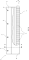
- Im Folgenden wird die Erfindung anhand von Zeichnungen näher beschrieben. Es zeigen:
- Figur 1a zeigt:
- Schematisch eine erfindungsgemäße Räumleiste in einer ersten Ausführungsform in einer 3D-Ansicht;
- Figur 1b zeigt:
- Schematisch die Räumleiste aus der
Figur 1a in Frontansicht; - Figur 1c zeigt:
- Schematisch einen Schnitt durch die Räumleiste aus der
Figur 1b entlang der Schnittlinie A-A; - Figur 1d zeigt:
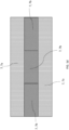
- Schematisch die Verschleißfläche einer der Räumleiste aus
Figur 1a ; - Figur 2 zeigt:
- Schematisch einen Querschnitt einer erfindungsgemäßen Räumleiste in einer zweiten Ausführungsform;
- Figur 3 zeigt:
- Schematisch einen Querschnitt einer erfindungsgemäßen Räumleiste in einer dritten Ausführungsform;
- Figur 4 a-e zeigen:
- Schematisch erfindungsgemäße Räumleisten in weiteren Ausführungsformen jeweils in einer 3D-Ansicht;
- In
Figur 1 a-d ist eine Räumleiste mit dem Bezugszeichen 1 bezeichnet. Die Räumleiste 1 weist einen stählernen Befestigungshals 2 auf. Am Befestigungshals 2 sind Bohrungen 3 vorgesehen, über die die Räumleiste 1 am Räumschild eines Schneepflugs mittels Schraubverbindungen befestigt wird. Es ist aber auch eine Verbindung mittels Klemmpratzen oder anderer Fügetechniken möglich, um erfindungsgemäße Räumleisten 1 am Räumschild zu befestigen. Am stählernen Befestigungshals 2 ist ein biegsamer Gummikörper 4 anvulkanisiert. In den Gummikörper 4 sind Kunststoff-Gleitkörper 5 eingefügt. Der Gummikörper 4 wird während der Herstellung in einem Vulkanisationsprozess stoffschlüssig mit dem stählernen Befestigungshals 2 und den Kunststoff-Gleitkörpern 5 verbunden. Der Gummikörper 4 bildet zusammen mit den Kunststoff-Gleitkörpern 5 den Verschleißabschnitt 6 der Räumleiste 1. Der Verschleißabschnitt 6 weist eine Verschleißfläche 7 auf, die während des Räumvorgangs im direkten Kontakt mit der zu räumenden Fläche tritt. Zudem weist der Räumkörper eine Verschleißhöhe 8 auf. Wenn der Räumkörper über die gesamte Verschleißhöhe 8 verschlissen ist, sollte die Räumleiste 1 ausgewechselt werden, weil das gewünschte Räumergebnis nicht mehr gewährleistet ist. - Während bei bekannten Gummi-Räumleisten die Verschleißfläche nur einen relativ stumpfen Gummianteil aufweist, wird die Verschleißfläche 7 bei einer erfindungsgemäßen Räumleiste 1 im Wesentlichen durch einen Gummiflächenanteil 7a und einen Kunststoffflächenanteil 7b gebildet. Durch die eingefügten Kunststoff-Gleitkörper 5 wird das Gleitverhalten der Räumleiste 1 massiv verbessert. Gleichzeitig behält sie ihre positiven Eigenschaften hinsichtlich der Biegsamkeit, der Elastizität und der Abriebfestigkeit. Während es bekannt war, reine Gummiräumleisten mit Hartstoff-Verschleißkörpern zu versehen, unter anderem um das Gleitverhalten zu verbessern, ging man in der Fachwelt Jahrzehnte davon aus, dass eine Kombination von Gummi und Kunststoff nicht zu realisieren sei. Kunststoff schien für den Vulkanisationsprozess nicht beständig genug. Zudem galt die stoffschlüssige Verbindung zwischen Gummi und Kunststoff als nicht realisierbar. Aufwendige Versuchsreihen und Untersuchungen der Anmelderin haben nun schließlich zu einem zufriedenstellenden Ergebnis geführt. Bei den anschließenden Einsatztest haben die erfindungsgemäßen Räumleisten 1 eine verbesserte Gleitfähigkeit gegenüber reinen Gummileisten sowie eine höhere Abriebfestigkeit und eine bessere Bruchfestigkeit gegenüber reinen Kunststoffleisten gezeigt.
- Besonders vorteilhaft hat sich dabei ein sandwichartiger Aufbau der Räumleiste 1, wie in
Figur 1a-d dargestellt, erwiesen. Die Verschleißfläche 7 der Räumleiste 1 ist schematisch inFigur 1d dargestellt. Sie weist jeweils einen in Fahrtrichtung F vorne und einen in Fahrtrichtung F hinten liegenden Gummiflächenanteil 7a auf. Dazwischen liegt ein Kunststoffflächenanteil 7b. Durch den sandwichartigen Aufbau sind die Kunststoff-Gleitkörper 5 beidseitig in den Gummikörper 4 eingebettet und die Verbindung ist somit besonders fest. - Für Einsatzgebiete, in denen die Gleitfähigkeit besonders wichtig ist, also mit relativ hoher Geschwindigkeit geräumt werden soll, ist eine Anordnung der Kunststoff-Gleitkörper 5 im Gummikörper 4 wie in
Figur 2 dargestellt vorteilhaft. Die Kunststoff-Gleitkörper 5 sind hier in Fahrtrichtung F vorne angeordnet, während der Gummiflächenanteil 7a dahinterliegt. Durch diesen hinteren Gummiflächenanteil 7a behält die Räumleiste 1 Ihre Abriebfestigkeit nahezu, wobei durch den vorderen Kunststoffflächenanteil 7b die Gleitfähigkeit weit verbessert wird. - Für Einsatzgebiete, in denen die Elastizität und die Abriebfestigkeit besonders wichtig sind, ist dagegen eine Anordnung der Kunststoff-Gleitkörper 5 im Gummikörper 4 wie in
Figur 3 dargestellt geeignet. Die Kunststoff-Gleitkörper 5 sind hier in Fahrtrichtung F hinten angeordnet, während der Gummiflächenanteil 7a davorliegt. Hierdurch ist die Räumleiste 1 besonders biegsam und sehr abriebfest. Gegenüber der Räumleiste 1 ausFigur 3 weist sie eine nur leicht verminderte Gleitfähigkeit auf. - In den
Figuren 4 a-e sind weitere Ausführungsformen dargestellt. Die Kunststoff-Gleitkörper 5 sind beispielsweise plattenförmig (Fig. 4a ,e ), dreiecksförmig (Fig. 4b ) oder zylinderförmig (Fig. 4c ) ausgebildet. Hierbei können die Kunststoff-Verschleißkörper 5 auch mehrreihig (Fig. 4d ) oder versetzt im Gummikörper 4 angeordnet sein. Über die Form, Größe und Positionierung der Kunststoff-Gleitkörper 5 kann das Verhältnis von Gummiflächenanteil 7a und Kunststoffflächenanteil 7b auf die Anforderungen an Gleitfähigkeit, Abriebfestigkeit und Bruchfestigkeit im Einsatzgebiet eingestellt werden. - Es kann zusätzlich vorteilhaft sein, die Form der Kunststoff-Gleitkörper 5 derart auszubilden, dass sie nach dem Vulkanisationsprozess formschlüssig in den Gummikörper 4 eingefügt sind, beispielsweise durch eine nicht dargestellte rippen- oder sägezahnförmige Oberfläche.
-
- 1
- Räumleiste
- 2
- Befestigungshals
- 3
- Bohrungen
- 4
- Gummikörper
- 5
- Kunststoff-Gleitkörper
- 6
- Verschleißabschnitt
- 7
- Verschleißfläche
- 7a
- Gummiflächenanteil
- 7b
- Kunststoff-Flächenanteil
- 8
- Verschleißhöhe
- F
- Fahrtrichtung
Claims (8)
- Räumleiste (1) für den Räumschild eines Schneepfluges mit einem Befestigungshals (2), an den ein langgestreckter Gummikörper (4) anvulkanisiert ist, welcher einen nach unten vorstehenden, frei biegsamen Verschleißabschnitt (6) mit einer Verschleißfläche (7) und einer Verschleißhöhe (8) aufweist,
dadurch gekennzeichnet,
dass über den Verschleißabschnitt (6) verteilt Kunststoff-Gleitkörper (5) eingefügt sind. - Räumleiste (1) nach Anspruch 1, dadurch gekennzeichnet, dass die Verschleißfläche (7) über mindestens 95% der Verschleißhöhe (8) einen Gummiflächenanteil (7a) und einen Kunststoffflächenanteil (7b) aufweist.
- Räumleiste (1) nach Anspruch 2, dadurch gekennzeichnet, dass das Verhältnis zwischen dem Gummiflächenanteil (7a) und dem Kunststoffflächenanteil (7b) über die gesamte Verschleißhöhe (8) im Wesentlichen gleich ist.
- Räumleiste (1) nach einem der Ansprüche 2-3, dadurch gekennzeichnet, dass die Verschleißfläche (7) sandwichartig einen vorderen und einen hinteren Gummiflächenanteil (7a) und eine dazwischenliegenden Kunststoffflächenanteil (7b) aufweist.
- Räumleiste (1) nach einem der Ansprüche 2-3, dadurch gekennzeichnet, dass der Kunststoffflächenanteil (7b) in Fahrtrichtung (F) vorne und der Gummiflächenanteil (7a) in Fahrtrichtung (F) hinten angeordnet ist.
- Räumleiste (1) nach einem der Ansprüche 2-3, dadurch gekennzeichnet, dass der Kunststoffflächenanteil (7b) in Fahrtrichtung (F) hinten und der Gummiflächenanteil (7a) in Fahrtrichtung (F) vorne angeordnet ist.
- Räumleiste (1) nach einem der Ansprüche 1-6, dadurch gekennzeichnet, dass die Kunststoff-Gleitkörper (5) formschlüssig in den Gummikörper (4) eingefügt sind.
- Räumleiste (1) nach einem der Ansprüche 1-7, dadurch gekennzeichnet, dass die Kunststoff-Gleitkörper (5) eine Quader- Dreiecks- und/oder Zylinderform aufweisen.
Applications Claiming Priority (2)
| Application Number | Priority Date | Filing Date | Title |
|---|---|---|---|
| DE102018125674.4A DE102018125674A1 (de) | 2018-10-16 | 2018-10-16 | Räumleiste für den Räumschild eines Schneepflugs |
| PCT/EP2019/077932 WO2020078988A1 (de) | 2018-10-16 | 2019-10-15 | Räumleiste für den räumschild eines schneepflugs |
Publications (3)
| Publication Number | Publication Date |
|---|---|
| EP3867450A1 EP3867450A1 (de) | 2021-08-25 |
| EP3867450B1 true EP3867450B1 (de) | 2023-10-04 |
| EP3867450C0 EP3867450C0 (de) | 2023-10-04 |
Family
ID=68468650
Family Applications (1)
| Application Number | Title | Priority Date | Filing Date |
|---|---|---|---|
| EP19798171.5A Active EP3867450B1 (de) | 2018-10-16 | 2019-10-15 | Räumleiste für den räumschild eines schneepflugs |
Country Status (4)
| Country | Link |
|---|---|
| US (1) | US20210381182A1 (de) |
| EP (1) | EP3867450B1 (de) |
| DE (1) | DE102018125674A1 (de) |
| WO (1) | WO2020078988A1 (de) |
Citations (1)
| Publication number | Priority date | Publication date | Assignee | Title |
|---|---|---|---|---|
| WO2006052196A1 (en) * | 2004-11-10 | 2006-05-18 | Metso Minerals (Wear Protection) Ab | Snowplough share and snowplough |
Family Cites Families (7)
| Publication number | Priority date | Publication date | Assignee | Title |
|---|---|---|---|---|
| US1719920A (en) * | 1924-02-18 | 1929-07-09 | Goodrich Co B F | Rubber composition and method of producing the same |
| DE2400440A1 (de) * | 1974-01-05 | 1975-07-17 | Gummi Kueper Kg | Raeumleiste fuer den raeumschild eines schneepfluges |
| US4347677A (en) * | 1979-02-05 | 1982-09-07 | Gummi Kuper Gmbh & Co. Kg | Snow removal bar for the snow removal plate of a snow plow |
| DE3518487A1 (de) * | 1985-05-23 | 1986-11-27 | Gummi-Küper GmbH & Co KG, 4630 Bochum | Raeumleiste fuer den raeumschild eines schneepfluges |
| DE102004029165A1 (de) * | 2004-06-17 | 2005-12-29 | Gummi Küper GmbH & Co KG | Sandwich-Räumleiste mit Hartmetallkern |
| DE102009051751A1 (de) * | 2009-11-03 | 2011-05-05 | Küper GmbH & Co.KG | Räumleiste für den Räumschild eines Schneepfluges |
| DE102016119769B3 (de) * | 2016-10-18 | 2018-03-01 | Küper Gmbh & Co. Kg | Räumleiste für den Räumschild eines Schneeplugs |
-
2018
- 2018-10-16 DE DE102018125674.4A patent/DE102018125674A1/de not_active Ceased
-
2019
- 2019-10-15 WO PCT/EP2019/077932 patent/WO2020078988A1/de not_active Ceased
- 2019-10-15 EP EP19798171.5A patent/EP3867450B1/de active Active
- 2019-10-15 US US17/283,078 patent/US20210381182A1/en not_active Abandoned
Patent Citations (1)
| Publication number | Priority date | Publication date | Assignee | Title |
|---|---|---|---|---|
| WO2006052196A1 (en) * | 2004-11-10 | 2006-05-18 | Metso Minerals (Wear Protection) Ab | Snowplough share and snowplough |
Also Published As
| Publication number | Publication date |
|---|---|
| DE102018125674A1 (de) | 2020-04-16 |
| EP3867450A1 (de) | 2021-08-25 |
| US20210381182A1 (en) | 2021-12-09 |
| EP3867450C0 (de) | 2023-10-04 |
| WO2020078988A1 (de) | 2020-04-23 |
Similar Documents
| Publication | Publication Date | Title |
|---|---|---|
| DE102010021187B4 (de) | Frontspoiler eines Kraftfahrzeugs | |
| DE8012313U1 (de) | Fahrzeugluftreifen | |
| DE19808196C2 (de) | Rotorblatt für einen Hubschrauber | |
| EP0828638B1 (de) | Wischblatt für scheiben von kraftfahrzeugen | |
| EP3088212A1 (de) | Fahrzeugluftreifen | |
| DE102011003025A1 (de) | Schienenfahrzeug mit einer Verkleidung für einen Wagenübergangsbereich | |
| DE10007808B4 (de) | Wischblatt | |
| EP0211380B1 (de) | Pistenfahrzeug mit höhenverstellbarer Bodenbearbeitungs-, insbesondere Schneefräsvorrichtung | |
| DE102013204637A1 (de) | Windenergieanlage | |
| EP3481649A1 (de) | Fahrzeugreifen | |
| WO2020078988A1 (de) | Räumleiste für den räumschild eines schneepflugs | |
| DE102015224289A1 (de) | Fahrzeugluftreifen | |
| DE102013226408A1 (de) | Scheibenwischvorrichtung mit integrierter Beleuchtung | |
| EP3350375B1 (de) | Räumleiste für den räumschild eines schneepflugs | |
| DE102013109501B4 (de) | Hybrid-Schleißschiene | |
| DE19856338B4 (de) | Abstreifvorrichtung für Förderbänder | |
| DE10324239B4 (de) | Pflugkörper mit Streichblech | |
| WO2010083909A1 (de) | Wischgummi | |
| DE3814240C2 (de) | Räumleiste für den Räumschild eines Schneepfluges | |
| DE102017124569B4 (de) | Spoilervorrichtung für einen Frontabschnitt eines Fahrzeugs | |
| AT521067B1 (de) | Laufwerkskette für eine pistenraupe und verfahren zur präparierung einer skipiste mit einer pistenraupe | |
| DE2900683C2 (de) | Bodenplatte für Gleisketten von Gleiskettenfahrzeugen | |
| DE2358977C2 (de) | Schlagkratzer für Enthaarungseinrichtungen | |
| DE102014215456A1 (de) | Scheibenwischvorrichtung für ein Fahrzeug | |
| DE102016216257A1 (de) | Wischgummi für Wischblätter von Scheibenwischern, Verfahren und Werkzeuge zu dessen Herstellung |
Legal Events
| Date | Code | Title | Description |
|---|---|---|---|
| STAA | Information on the status of an ep patent application or granted ep patent |
Free format text: STATUS: UNKNOWN |
|
| STAA | Information on the status of an ep patent application or granted ep patent |
Free format text: STATUS: THE INTERNATIONAL PUBLICATION HAS BEEN MADE |
|
| PUAI | Public reference made under article 153(3) epc to a published international application that has entered the european phase |
Free format text: ORIGINAL CODE: 0009012 |
|
| STAA | Information on the status of an ep patent application or granted ep patent |
Free format text: STATUS: REQUEST FOR EXAMINATION WAS MADE |
|
| 17P | Request for examination filed |
Effective date: 20210517 |
|
| AK | Designated contracting states |
Kind code of ref document: A1 Designated state(s): AL AT BE BG CH CY CZ DE DK EE ES FI FR GB GR HR HU IE IS IT LI LT LU LV MC MK MT NL NO PL PT RO RS SE SI SK SM TR |
|
| DAV | Request for validation of the european patent (deleted) | ||
| DAX | Request for extension of the european patent (deleted) | ||
| STAA | Information on the status of an ep patent application or granted ep patent |
Free format text: STATUS: EXAMINATION IS IN PROGRESS |
|
| 17Q | First examination report despatched |
Effective date: 20220830 |
|
| GRAP | Despatch of communication of intention to grant a patent |
Free format text: ORIGINAL CODE: EPIDOSNIGR1 |
|
| STAA | Information on the status of an ep patent application or granted ep patent |
Free format text: STATUS: GRANT OF PATENT IS INTENDED |
|
| INTG | Intention to grant announced |
Effective date: 20230413 |
|
| GRAS | Grant fee paid |
Free format text: ORIGINAL CODE: EPIDOSNIGR3 |
|
| GRAA | (expected) grant |
Free format text: ORIGINAL CODE: 0009210 |
|
| STAA | Information on the status of an ep patent application or granted ep patent |
Free format text: STATUS: THE PATENT HAS BEEN GRANTED |
|
| AK | Designated contracting states |
Kind code of ref document: B1 Designated state(s): AL AT BE BG CH CY CZ DE DK EE ES FI FR GB GR HR HU IE IS IT LI LT LU LV MC MK MT NL NO PL PT RO RS SE SI SK SM TR |
|
| REG | Reference to a national code |
Ref country code: GB Ref legal event code: FG4D Free format text: NOT ENGLISH |
|
| REG | Reference to a national code |
Ref country code: CH Ref legal event code: EP |
|
| REG | Reference to a national code |
Ref country code: DE Ref legal event code: R096 Ref document number: 502019009585 Country of ref document: DE |
|
| REG | Reference to a national code |
Ref country code: IE Ref legal event code: FG4D Free format text: LANGUAGE OF EP DOCUMENT: GERMAN |
|
| U01 | Request for unitary effect filed |
Effective date: 20231026 |
|
| U07 | Unitary effect registered |
Designated state(s): AT BE BG DE DK EE FI FR IT LT LU LV MT NL PT SE SI Effective date: 20231113 |
|
| U20 | Renewal fee for the european patent with unitary effect paid |
Year of fee payment: 5 Effective date: 20231213 |
|
| PG25 | Lapsed in a contracting state [announced via postgrant information from national office to epo] |
Ref country code: GR Free format text: LAPSE BECAUSE OF FAILURE TO SUBMIT A TRANSLATION OF THE DESCRIPTION OR TO PAY THE FEE WITHIN THE PRESCRIBED TIME-LIMIT Effective date: 20240105 |
|
| PG25 | Lapsed in a contracting state [announced via postgrant information from national office to epo] |
Ref country code: IS Free format text: LAPSE BECAUSE OF FAILURE TO SUBMIT A TRANSLATION OF THE DESCRIPTION OR TO PAY THE FEE WITHIN THE PRESCRIBED TIME-LIMIT Effective date: 20240204 |
|
| PG25 | Lapsed in a contracting state [announced via postgrant information from national office to epo] |
Ref country code: ES Free format text: LAPSE BECAUSE OF FAILURE TO SUBMIT A TRANSLATION OF THE DESCRIPTION OR TO PAY THE FEE WITHIN THE PRESCRIBED TIME-LIMIT Effective date: 20231004 |
|
| PG25 | Lapsed in a contracting state [announced via postgrant information from national office to epo] |
Ref country code: IS Free format text: LAPSE BECAUSE OF FAILURE TO SUBMIT A TRANSLATION OF THE DESCRIPTION OR TO PAY THE FEE WITHIN THE PRESCRIBED TIME-LIMIT Effective date: 20240204 Ref country code: GR Free format text: LAPSE BECAUSE OF FAILURE TO SUBMIT A TRANSLATION OF THE DESCRIPTION OR TO PAY THE FEE WITHIN THE PRESCRIBED TIME-LIMIT Effective date: 20240105 Ref country code: ES Free format text: LAPSE BECAUSE OF FAILURE TO SUBMIT A TRANSLATION OF THE DESCRIPTION OR TO PAY THE FEE WITHIN THE PRESCRIBED TIME-LIMIT Effective date: 20231004 |
|
| PG25 | Lapsed in a contracting state [announced via postgrant information from national office to epo] |
Ref country code: RS Free format text: LAPSE BECAUSE OF FAILURE TO SUBMIT A TRANSLATION OF THE DESCRIPTION OR TO PAY THE FEE WITHIN THE PRESCRIBED TIME-LIMIT Effective date: 20231004 Ref country code: PL Free format text: LAPSE BECAUSE OF FAILURE TO SUBMIT A TRANSLATION OF THE DESCRIPTION OR TO PAY THE FEE WITHIN THE PRESCRIBED TIME-LIMIT Effective date: 20231004 Ref country code: NO Free format text: LAPSE BECAUSE OF FAILURE TO SUBMIT A TRANSLATION OF THE DESCRIPTION OR TO PAY THE FEE WITHIN THE PRESCRIBED TIME-LIMIT Effective date: 20240104 Ref country code: HR Free format text: LAPSE BECAUSE OF FAILURE TO SUBMIT A TRANSLATION OF THE DESCRIPTION OR TO PAY THE FEE WITHIN THE PRESCRIBED TIME-LIMIT Effective date: 20231004 |
|
| REG | Reference to a national code |
Ref country code: CH Ref legal event code: PL |
|
| REG | Reference to a national code |
Ref country code: DE Ref legal event code: R097 Ref document number: 502019009585 Country of ref document: DE |
|
| PG25 | Lapsed in a contracting state [announced via postgrant information from national office to epo] |
Ref country code: CH Free format text: LAPSE BECAUSE OF NON-PAYMENT OF DUE FEES Effective date: 20231031 |
|
| PG25 | Lapsed in a contracting state [announced via postgrant information from national office to epo] |
Ref country code: CZ Free format text: LAPSE BECAUSE OF FAILURE TO SUBMIT A TRANSLATION OF THE DESCRIPTION OR TO PAY THE FEE WITHIN THE PRESCRIBED TIME-LIMIT Effective date: 20231004 |
|
| PG25 | Lapsed in a contracting state [announced via postgrant information from national office to epo] |
Ref country code: SK Free format text: LAPSE BECAUSE OF FAILURE TO SUBMIT A TRANSLATION OF THE DESCRIPTION OR TO PAY THE FEE WITHIN THE PRESCRIBED TIME-LIMIT Effective date: 20231004 |
|
| PG25 | Lapsed in a contracting state [announced via postgrant information from national office to epo] |
Ref country code: SM Free format text: LAPSE BECAUSE OF FAILURE TO SUBMIT A TRANSLATION OF THE DESCRIPTION OR TO PAY THE FEE WITHIN THE PRESCRIBED TIME-LIMIT Effective date: 20231004 Ref country code: SK Free format text: LAPSE BECAUSE OF FAILURE TO SUBMIT A TRANSLATION OF THE DESCRIPTION OR TO PAY THE FEE WITHIN THE PRESCRIBED TIME-LIMIT Effective date: 20231004 Ref country code: RO Free format text: LAPSE BECAUSE OF FAILURE TO SUBMIT A TRANSLATION OF THE DESCRIPTION OR TO PAY THE FEE WITHIN THE PRESCRIBED TIME-LIMIT Effective date: 20231004 Ref country code: CZ Free format text: LAPSE BECAUSE OF FAILURE TO SUBMIT A TRANSLATION OF THE DESCRIPTION OR TO PAY THE FEE WITHIN THE PRESCRIBED TIME-LIMIT Effective date: 20231004 Ref country code: CH Free format text: LAPSE BECAUSE OF NON-PAYMENT OF DUE FEES Effective date: 20231031 |
|
| PLBE | No opposition filed within time limit |
Free format text: ORIGINAL CODE: 0009261 |
|
| STAA | Information on the status of an ep patent application or granted ep patent |
Free format text: STATUS: NO OPPOSITION FILED WITHIN TIME LIMIT |
|
| PG25 | Lapsed in a contracting state [announced via postgrant information from national office to epo] |
Ref country code: MC Free format text: LAPSE BECAUSE OF FAILURE TO SUBMIT A TRANSLATION OF THE DESCRIPTION OR TO PAY THE FEE WITHIN THE PRESCRIBED TIME-LIMIT Effective date: 20231004 |
|
| PG25 | Lapsed in a contracting state [announced via postgrant information from national office to epo] |
Ref country code: MC Free format text: LAPSE BECAUSE OF FAILURE TO SUBMIT A TRANSLATION OF THE DESCRIPTION OR TO PAY THE FEE WITHIN THE PRESCRIBED TIME-LIMIT Effective date: 20231004 |
|
| 26N | No opposition filed |
Effective date: 20240705 |
|
| GBPC | Gb: european patent ceased through non-payment of renewal fee |
Effective date: 20240104 |
|
| PG25 | Lapsed in a contracting state [announced via postgrant information from national office to epo] |
Ref country code: IE Free format text: LAPSE BECAUSE OF NON-PAYMENT OF DUE FEES Effective date: 20231015 |
|
| PG25 | Lapsed in a contracting state [announced via postgrant information from national office to epo] |
Ref country code: GB Free format text: LAPSE BECAUSE OF NON-PAYMENT OF DUE FEES Effective date: 20240104 |
|
| PG25 | Lapsed in a contracting state [announced via postgrant information from national office to epo] |
Ref country code: IE Free format text: LAPSE BECAUSE OF NON-PAYMENT OF DUE FEES Effective date: 20231015 Ref country code: GB Free format text: LAPSE BECAUSE OF NON-PAYMENT OF DUE FEES Effective date: 20240104 |
|
| U20 | Renewal fee for the european patent with unitary effect paid |
Year of fee payment: 6 Effective date: 20241025 |
|
| PG25 | Lapsed in a contracting state [announced via postgrant information from national office to epo] |
Ref country code: CY Free format text: LAPSE BECAUSE OF FAILURE TO SUBMIT A TRANSLATION OF THE DESCRIPTION OR TO PAY THE FEE WITHIN THE PRESCRIBED TIME-LIMIT; INVALID AB INITIO Effective date: 20191015 |
|
| PG25 | Lapsed in a contracting state [announced via postgrant information from national office to epo] |
Ref country code: HU Free format text: LAPSE BECAUSE OF FAILURE TO SUBMIT A TRANSLATION OF THE DESCRIPTION OR TO PAY THE FEE WITHIN THE PRESCRIBED TIME-LIMIT; INVALID AB INITIO Effective date: 20191015 |
|
| U20 | Renewal fee for the european patent with unitary effect paid |
Year of fee payment: 7 Effective date: 20251028 |
|
| PG25 | Lapsed in a contracting state [announced via postgrant information from national office to epo] |
Ref country code: TR Free format text: LAPSE BECAUSE OF FAILURE TO SUBMIT A TRANSLATION OF THE DESCRIPTION OR TO PAY THE FEE WITHIN THE PRESCRIBED TIME-LIMIT Effective date: 20231004 |