EP3866267A1 - Leiteranschlussklemme - Google Patents
Leiteranschlussklemme Download PDFInfo
- Publication number
- EP3866267A1 EP3866267A1 EP21157524.6A EP21157524A EP3866267A1 EP 3866267 A1 EP3866267 A1 EP 3866267A1 EP 21157524 A EP21157524 A EP 21157524A EP 3866267 A1 EP3866267 A1 EP 3866267A1
- Authority
- EP
- European Patent Office
- Prior art keywords
- conductor
- clamping
- connection terminal
- section
- receiving section
- Prior art date
- Legal status (The legal status is an assumption and is not a legal conclusion. Google has not performed a legal analysis and makes no representation as to the accuracy of the status listed.)
- Granted
Links
Images


Classifications
-
- H—ELECTRICITY
- H01—ELECTRIC ELEMENTS
- H01R—ELECTRICALLY-CONDUCTIVE CONNECTIONS; STRUCTURAL ASSOCIATIONS OF A PLURALITY OF MUTUALLY-INSULATED ELECTRICAL CONNECTING ELEMENTS; COUPLING DEVICES; CURRENT COLLECTORS
- H01R11/00—Individual connecting elements providing two or more spaced connecting locations for conductive members which are, or may be, thereby interconnected, e.g. end pieces for wires or cables supported by the wire or cable and having means for facilitating electrical connection to some other wire, terminal, or conductive member, blocks of binding posts
- H01R11/03—Individual connecting elements providing two or more spaced connecting locations for conductive members which are, or may be, thereby interconnected, e.g. end pieces for wires or cables supported by the wire or cable and having means for facilitating electrical connection to some other wire, terminal, or conductive member, blocks of binding posts characterised by the relationship between the connecting locations
- H01R11/09—Individual connecting elements providing two or more spaced connecting locations for conductive members which are, or may be, thereby interconnected, e.g. end pieces for wires or cables supported by the wire or cable and having means for facilitating electrical connection to some other wire, terminal, or conductive member, blocks of binding posts characterised by the relationship between the connecting locations the connecting locations being identical
-
- H—ELECTRICITY
- H01—ELECTRIC ELEMENTS
- H01R—ELECTRICALLY-CONDUCTIVE CONNECTIONS; STRUCTURAL ASSOCIATIONS OF A PLURALITY OF MUTUALLY-INSULATED ELECTRICAL CONNECTING ELEMENTS; COUPLING DEVICES; CURRENT COLLECTORS
- H01R11/00—Individual connecting elements providing two or more spaced connecting locations for conductive members which are, or may be, thereby interconnected, e.g. end pieces for wires or cables supported by the wire or cable and having means for facilitating electrical connection to some other wire, terminal, or conductive member, blocks of binding posts
- H01R11/01—Individual connecting elements providing two or more spaced connecting locations for conductive members which are, or may be, thereby interconnected, e.g. end pieces for wires or cables supported by the wire or cable and having means for facilitating electrical connection to some other wire, terminal, or conductive member, blocks of binding posts characterised by the form or arrangement of the conductive interconnection between the connecting locations
-
- H—ELECTRICITY
- H01—ELECTRIC ELEMENTS
- H01R—ELECTRICALLY-CONDUCTIVE CONNECTIONS; STRUCTURAL ASSOCIATIONS OF A PLURALITY OF MUTUALLY-INSULATED ELECTRICAL CONNECTING ELEMENTS; COUPLING DEVICES; CURRENT COLLECTORS
- H01R13/00—Details of coupling devices of the kinds covered by groups H01R12/70 or H01R24/00 - H01R33/00
- H01R13/40—Securing contact members in or to a base or case; Insulating of contact members
- H01R13/42—Securing in a demountable manner
-
- H—ELECTRICITY
- H01—ELECTRIC ELEMENTS
- H01R—ELECTRICALLY-CONDUCTIVE CONNECTIONS; STRUCTURAL ASSOCIATIONS OF A PLURALITY OF MUTUALLY-INSULATED ELECTRICAL CONNECTING ELEMENTS; COUPLING DEVICES; CURRENT COLLECTORS
- H01R13/00—Details of coupling devices of the kinds covered by groups H01R12/70 or H01R24/00 - H01R33/00
- H01R13/46—Bases; Cases
- H01R13/502—Bases; Cases composed of different pieces
-
- H—ELECTRICITY
- H01—ELECTRIC ELEMENTS
- H01R—ELECTRICALLY-CONDUCTIVE CONNECTIONS; STRUCTURAL ASSOCIATIONS OF A PLURALITY OF MUTUALLY-INSULATED ELECTRICAL CONNECTING ELEMENTS; COUPLING DEVICES; CURRENT COLLECTORS
- H01R4/00—Electrically-conductive connections between two or more conductive members in direct contact, i.e. touching one another; Means for effecting or maintaining such contact; Electrically-conductive connections having two or more spaced connecting locations for conductors and using contact members penetrating insulation
- H01R4/28—Clamped connections, spring connections
- H01R4/48—Clamped connections, spring connections utilising a spring, clip, or other resilient member
- H01R4/4809—Clamped connections, spring connections utilising a spring, clip, or other resilient member using a leaf spring to bias the conductor toward the busbar
- H01R4/4846—Busbar details
- H01R4/485—Single busbar common to multiple springs
-
- H—ELECTRICITY
- H01—ELECTRIC ELEMENTS
- H01R—ELECTRICALLY-CONDUCTIVE CONNECTIONS; STRUCTURAL ASSOCIATIONS OF A PLURALITY OF MUTUALLY-INSULATED ELECTRICAL CONNECTING ELEMENTS; COUPLING DEVICES; CURRENT COLLECTORS
- H01R9/00—Structural associations of a plurality of mutually-insulated electrical connecting elements, e.g. terminal strips or terminal blocks; Terminals or binding posts mounted upon a base or in a case; Bases therefor
- H01R9/22—Bases, e.g. strip, block, panel
- H01R9/24—Terminal blocks
- H01R9/2416—Means for guiding or retaining wires or cables connected to terminal blocks
-
- H—ELECTRICITY
- H01—ELECTRIC ELEMENTS
- H01R—ELECTRICALLY-CONDUCTIVE CONNECTIONS; STRUCTURAL ASSOCIATIONS OF A PLURALITY OF MUTUALLY-INSULATED ELECTRICAL CONNECTING ELEMENTS; COUPLING DEVICES; CURRENT COLLECTORS
- H01R4/00—Electrically-conductive connections between two or more conductive members in direct contact, i.e. touching one another; Means for effecting or maintaining such contact; Electrically-conductive connections having two or more spaced connecting locations for conductors and using contact members penetrating insulation
- H01R4/26—Connections in which at least one of the connecting parts has projections which bite into or engage the other connecting part in order to improve the contact
-
- H—ELECTRICITY
- H01—ELECTRIC ELEMENTS
- H01R—ELECTRICALLY-CONDUCTIVE CONNECTIONS; STRUCTURAL ASSOCIATIONS OF A PLURALITY OF MUTUALLY-INSULATED ELECTRICAL CONNECTING ELEMENTS; COUPLING DEVICES; CURRENT COLLECTORS
- H01R4/00—Electrically-conductive connections between two or more conductive members in direct contact, i.e. touching one another; Means for effecting or maintaining such contact; Electrically-conductive connections having two or more spaced connecting locations for conductors and using contact members penetrating insulation
- H01R4/28—Clamped connections, spring connections
- H01R4/48—Clamped connections, spring connections utilising a spring, clip, or other resilient member
- H01R4/4809—Clamped connections, spring connections utilising a spring, clip, or other resilient member using a leaf spring to bias the conductor toward the busbar
- H01R4/48185—Clamped connections, spring connections utilising a spring, clip, or other resilient member using a leaf spring to bias the conductor toward the busbar adapted for axial insertion of a wire end
- H01R4/4819—Clamped connections, spring connections utilising a spring, clip, or other resilient member using a leaf spring to bias the conductor toward the busbar adapted for axial insertion of a wire end the spring shape allowing insertion of the conductor end when the spring is unbiased
- H01R4/4821—Single-blade spring
-
- H—ELECTRICITY
- H01—ELECTRIC ELEMENTS
- H01R—ELECTRICALLY-CONDUCTIVE CONNECTIONS; STRUCTURAL ASSOCIATIONS OF A PLURALITY OF MUTUALLY-INSULATED ELECTRICAL CONNECTING ELEMENTS; COUPLING DEVICES; CURRENT COLLECTORS
- H01R4/00—Electrically-conductive connections between two or more conductive members in direct contact, i.e. touching one another; Means for effecting or maintaining such contact; Electrically-conductive connections having two or more spaced connecting locations for conductors and using contact members penetrating insulation
- H01R4/28—Clamped connections, spring connections
- H01R4/48—Clamped connections, spring connections utilising a spring, clip, or other resilient member
- H01R4/4809—Clamped connections, spring connections utilising a spring, clip, or other resilient member using a leaf spring to bias the conductor toward the busbar
- H01R4/4828—Spring-activating arrangements mounted on or integrally formed with the spring housing
- H01R4/483—Pivoting arrangements, e.g. lever pushing on the spring
-
- H—ELECTRICITY
- H01—ELECTRIC ELEMENTS
- H01R—ELECTRICALLY-CONDUCTIVE CONNECTIONS; STRUCTURAL ASSOCIATIONS OF A PLURALITY OF MUTUALLY-INSULATED ELECTRICAL CONNECTING ELEMENTS; COUPLING DEVICES; CURRENT COLLECTORS
- H01R4/00—Electrically-conductive connections between two or more conductive members in direct contact, i.e. touching one another; Means for effecting or maintaining such contact; Electrically-conductive connections having two or more spaced connecting locations for conductors and using contact members penetrating insulation
- H01R4/28—Clamped connections, spring connections
- H01R4/48—Clamped connections, spring connections utilising a spring, clip, or other resilient member
- H01R4/4809—Clamped connections, spring connections utilising a spring, clip, or other resilient member using a leaf spring to bias the conductor toward the busbar
- H01R4/4846—Busbar details
- H01R4/4852—Means for improving the contact with the conductor, e.g. uneven wire-receiving surface
Definitions
- the invention relates to a conductor connection terminal with an insulating material housing, with a busbar component, with a first clamping limb and a second clamping limb, the first clamping limb and the second clamping limb being arranged on a clamping spring or each on different clamping springs, the first clamping limb and the busbar component being a first
- the clamping point for a first electrical conductor to be clamped and the second clamping leg and the busbar component form a second clamping point for a second electrical conductor to be clamped
- the busbar component having a first conductor receiving section and a second conductor receiving section in diametrically opposite regions, the first conductor receiving section and the second conductor receiving section are connected to one another via a connecting section, the first electrical conductor in a first conductor via the first conductor receiving section guiding direction and the second electrical conductor can be fed via the second conductor receiving section in a second conductor insertion direction of the respective clamping point and wherein the busbar component has a bottom
- DE 20 2016 105 702 U1 discloses a conductor terminal with a contact insert, the contact insert having a retaining frame.
- the holding frame is formed from several mutually aligned side walls. One of the side walls is positively connected to another side wall.
- the object of the present invention is to create an improved conductor connection terminal.
- the first conductor receiving section and the second conductor receiving section are designed to be closed on the circumference, the connecting section having at least one recess within the bottom section.
- the busbar component can in particular be designed in one piece.
- a latching edge can be provided on the busbar component through the recess.
- This latching edge can be used, for example, in such a way that one or more latching connections are arranged on the insulating material housing, which engage around the busbar component and latch on the latching edge of the recess.
- the busbar component can have a fastening element for fastening the clamping spring to the busbar component.
- the fastening element is designed as a fastening tab.
- clamping spring can be suspended in the fastening strap in a self-supporting manner. This has the advantage that the clamping spring can be fastened to the busbar without additional fastening means.
- the recess of the connecting section can be arranged essentially centrally between the first conductor receiving section and the second conductor receiving section.
- the recess can extend over the side surfaces.
- the recess is U-shaped in a cross section perpendicular to the first conductor insertion direction and / or to the second conductor insertion direction.
- the U-shaped recess can further save material and provide a higher-lying locking edge
- the ceiling surface can be designed as a ladder run-up slope.
- the ceiling surface can be V-shaped in a cross section in the direction of the first conductor insertion direction and / or the second conductor insertion direction.
- the ceiling surface By designing the ceiling surface as a ladder run-up slope, existing contours can be used to facilitate the introduction of an electrical conductor.
- the ceiling surface can be designed to rise counter to the first conductor insertion direction and / or the second conductor insertion direction.
- a funnel-shaped first and / or second conductor receiving section that widens against the direction of conductor insertion is created for guiding the first electrical conductor and / or the second electrical conductor.
- the electrical conductors to be clamped can be inserted into the respective conductor receiving section with a large cross section, the cross section tapering towards the respective clamping point, so that the electrical conductors can be securely clamped in the respective clamping points.
- the clamping spring can have a contact limb, a clamping limb and a spring bow arranged between the contact limb and the clamping limb, the clamping limb extending towards the busbar component and having a spring clamping edge for clamping the first electrical conductor and / or the second electrical conductor.
- a conductor stop for positioning the first electrical conductor to be clamped and / or the second electrical conductor to be clamped can be attached to the conductor connection terminal be arranged electrical conductor, wherein the conductor stop is arranged in the region of the recess. Furthermore, the conductor stop can be arranged on the insulating material housing.
- the conductor stop is used to correctly position the electrical conductor to be clamped.
- the electrical conductors are fed into the conductor connection terminal until a deeper guide is blocked by the conductor stop.
- the electrical conductors to be clamped can then be clamped in this position.
- a conductor stop is provided for the first electrical conductor to be clamped and for the second electrical conductor to be clamped. Opposite sides of the conductor stop are then each assigned to one of the electrical conductors to be clamped.
- a separate conductor stop is assigned to each electrical conductor to be clamped.
- the conductor stop In order to provide a conductor stop in a structurally simple manner, it can be arranged on the insulating material housing, the conductor stop engaging in the recess of the busbar component. However, it is also possible that the conductor stop is arranged, for example, on the busbar component itself and protrudes into the recess of the busbar component.
- the insulating material housing can be transparent at least in the area of the conductor stop, the conductor stop being visible through the insulating material housing.
- a transparent insulating material housing enables the insertion depth of the electrical conductors to be clamped to be checked, with the user being able to actively control through the housing whether the respective electrical conductor is positioned at the conductor stop.
- markings are arranged on the busbar component and / or on the insulating material housing, the markings indicating the minimum insertion depth of the first electrical conductor and / or of the second electrical conductor.
- the minimum insertion depth is the depth at which the electrical conductors can be securely clamped to the busbar component can be guaranteed.
- markings can be designed as colored markings or as notches, for example
- a test opening can be arranged on the insulating material housing, the test opening being oriented transversely to the first electrical conductor to be clamped and / or transversely to the second electrical conductor to be clamped and extending from the surface of the insulating material housing through the insulating material housing to the busbar component.
- the busbar component can be contacted with external measuring devices through such a test opening.
- the conductor connection terminal can have an actuating lever, the actuating lever being set up to deflect the first clamping leg and / or the second clamping leg.
- the conductor connection terminal can have a support surface for the actuating lever.
- the conductor connection terminal has at least two actuation levers, one actuation lever in each case interacting with one of the clamping legs, so that an actuation lever is set up for opening and / or closing a clamping point.
- the terminal points can then be opened or closed independently of one another. A release of the electrical conductor from the clamping point is preferably not possible without actuating a lever.
- the support for the actuating lever enables a closed flow of force through the conductor connection terminal, so that point load peaks can be reduced.
- the support can be implemented, for example, as a support bracket, the support bracket being arranged in the first conductor insertion direction or the second conductor insertion direction or a support bracket in both conductor insertion directions in front of the conductor receiving section. It is conceivable that the support, for example, on the insulating material housing and / or the clamping spring and / or the busbar component is arranged.
- the recess can be closed by the insulating material housing.
- the recess can be closed, for example, in such a way that the insulating material housing protrudes into the recess or the insulating material housing is guided past the recess from the outside in the immediate or indirect vicinity.
- the conductor connection terminal according to the invention has a large number of busbar components arranged next to one another.
- busbar components For example, two, three, four or five busbar components can be arranged next to one another in an insulating material housing, the busbar components each having two clamping springs for two electrical conductors to be clamped on.
- Figure 1 shows a conductor connection terminal 1 in a perspective view in a first embodiment.
- the conductor connection terminal 1 has a busbar component 2, a first clamping spring 3a and a second clamping spring 3b being arranged at each of the diametrically opposite ends of the busbar component 2.
- the clamping springs 3a, 3b each have a contact leg 4a, 4b, which merges into a spring arch 5a, 5b and extends into a clamping leg 6a, 6b.
- the clamping limb 6a, 6b extends to a section of the busbar component 2, the clamping limb 6a, 6b having a spring clamping edge 7a, 7b and with the busbar component 2 a first clamping point for a first electrical conductor to be clamped and a second clamping point for a second electrical conductor to be clamped Head forms.
- a first conductor receiving section 8a for the first electrical conductor to be clamped and a second conductor receiving section 8b for the second electrical conductor to be clamped are arranged at each of the diametrically opposite ends of the busbar component 2.
- the conductor receiving sections 8a, 8b are designed to be closed on the circumferential side.
- the conductor receiving sections 8a, 8b have a ceiling section 9a, 9b of a ceiling surface 9 assigned to the contact leg 4a, 4b and a floor section 12 assigned to the spring clamping edge 7a, 7b, the respective ceiling section 9a, 9b and the floor section 12 being connected to one another via two side surfaces 13 and form a continuous, circumferentially closed conductor receiving section 8a, 8b.
- the conductor receiving sections 8a, 8b are connected to one another via a connecting section 8c, the conductor receiving sections 8a, 8b and the connecting section 8c having the common ceiling surface 9.
- the busbar component 2 each has a preferably integrally molded tab-shaped conductor contact section 2a, 2b, on which the spring clamping edge 7a, 7b preferably rests in the closed state without an inserted electrical conductor .
- fastening tabs 10a, 10b are arranged on the ceiling surface 9 of the busbar component 2, the fastening tabs 10a, 10b each being arranged at the diametrically opposite ends of the ceiling surface 9.
- One of the clamping springs 3a, 3b is in each case suspended in the fastening tabs 10a, 10b in a self-supporting manner, that is to say without additional fastening means.
- clamping springs 3a, 3b are designed as a single clamping spring with two clamping legs 7a, 7b, the single clamping spring extending on the ceiling surface 9 of the busbar component 2.
- Figure 2a shows a conductor connection terminal 1 according to Figure 1 in a sectioned side view with no electrical conductor inserted.
- the busbar component 2 in the area of the spring clamping edges 7a, 7b each has a busbar clamping edge 11a, 11b.
- the busbar clamping edges 11a, 11b can advantageously be provided in the area of the conductor contact sections 2a, 2b.
- the busbar clamping edges 11a, 11b have a radius less than or equal to 0.2 mm, in particular a radius less than or equal to 0.1.
- the busbar clamping edges 11a, 11b are so sharp that they can cut into an electrical to be clamped and the busbar clamping edge 11a, 11b thus digs into the electrical conductor to be clamped, with a corresponding conductor holding force can be reached.
- busbar clamping edges 11a, 11b have even smaller radii. The effect of cutting into the electrical conductor is further improved.
- the bottom section 12 of the busbar component 2 can form a support for the electrical conductors to be clamped.
- the bottom section 12 can include the tab-shaped conductor contact sections 2a, 2b.
- the bottom section 12 and the top surface 9 are connected to one another via two opposing side surfaces 13. It becomes clear that the bottom section 12 and the side surfaces 13 have a recess 14 in the area of the connecting section 8c.
- the recess 14 is arranged essentially centrally between the first conductor receiving section 8a and the second conductor receiving section 8b. Essentially centrally means that the recess 14 is arranged in such a way that the conductor receiving sections 8a, 8b have the same length. Deviations of up to 15% are possible.
- the recess 14 extends over half of the connecting section 8c. Half of this relates to the area that the recess 14 occupies in the side view.
- the busbar component 2 is formed in a U-shaped cross section through the recess 14, which extends over the bottom section 12 and both side surfaces 13. Due to the U-shaped design, a good current flow and a stable conductor connection terminal 1 can be ensured.
- the ceiling surface 9 is designed as a ladder run-up slope, the ceiling surface 9 being V-shaped.
- the cross section of the conductor receiving sections 8a, 8b tapers towards the center of the conductor connection terminal 1 as far as the area of the connecting section 8c. In this way, a corresponding electrical conductor can be inserted into the larger cross section of the conductor receiving sections 8a, 8b, the electrical conductor being able to be guided through the tapering cross section to the respective clamping point.
- Figure 2b shows an enlarged section of the conductor connection terminal 1 according to Figure 2a.
- the area around the busbar clamping edge 11a is shown enlarged. It would be clear that the busbar clamping edge 11a is arranged on a busbar clamping section 18.
- the busbar clamping section 18 is cut or punched out of the busbar component 2.
- the busbar component 2 has a recess 15 and a recess 16, the recess 15 being arranged behind the busbar clamping edge 11a in relation to the first conductor insertion direction L1 and the recess 16 in relation to the first conductor insertion direction L1 being arranged in front of the busbar clamping edge 11a .
- the recess 16 is designed in such a way that it can accommodate the spring clamping edge 7a when no electrical conductor is plugged into the conductor connection terminal 1. In this way, the clamping spring 3a can be further stabilized, and the transport safety of the conductor connection terminal 1 can be increased.
- a busbar clamping edge 11a can be created at a sufficient height in relation to the busbar so that the busbar clamping edge 11a can dig into the electrical conductor to be clamped at this height.
- Figure 3a shows a conductor connection terminal 1 according to Figures 1-2b in a sectional side view with an inserted first electrical conductor 17.
- FIG. 3b shows an enlarged section of the conductor connection terminal 1 according to FIG Figure 3a . The area around the busbar clamping edge 11a is shown enlarged.
- the busbar clamping edge 11a is designed as a barbed hook, the busbar clamping edge 11a cutting into the first electrical conductor 17 opposite to the first conductor insertion direction L1 when the first electrical conductor 17 is pulled and thus digs into the first electrical conductor 17. In this way, a correspondingly high holding force can be exerted on the first electrical conductor 17, wherein the first electrical conductor 17 can be held fixed in the clamping point of the conductor connection terminal 1.
- a second electrical conductor could be clamped to the diametrically opposite end of the clamped-on first electrical conductor 17 in the same way.
- the busbar clamping edge 11a can be made more rigid than the spring clamping edge 7a. Due to the increased rigidity of the busbar clamping edge 11a compared to the clamping spring 7a, it can be ensured that the busbar clamping edge 11a intersects the electrical conductor to be clamped.
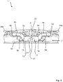
- Figure 4 shows a conductor connection terminal 1 with an insulating housing 19 in a side sectional view with a busbar component 2 arranged in the insulating housing 19.
- Two clamping springs 3a, 3b are arranged on the busbar component 2 at diametrically opposite ends.
- the clamping springs 3a, 3b have a contact leg 4a, 4b which merges into a spring arch 5a, 5b and extends into a clamping leg 6a, 6b.
- the clamping legs 6a, 6b each have a spring clamping edge 7a, 7b, the spring clamping edges 7a, 7b with the busbar component 2 forming a first clamping point for a first electrical conductor to be clamped and a second clamping point for a second electrical conductor to be clamped.
- the conductor connection terminal 1 has two actuation levers 20a, 20b, one actuation lever 20a, 20b each interacting with a clamping spring 3a, 3b, so that the actuation levers 20a, 20b are set up to deflect the clamping legs 6a, 6b.
- the terminal points for the electrical conductors can be opened and / or closed by the operating lever.
- the conductor connection terminal 1 has a conductor stop 21, the conductor stop 21 being arranged on the insulating material housing 2.
- the conductor stop is used to position the first electrical conductor to be clamped and the second electrical conductor to be clamped, the conductor stop 21 being arranged in the region of the recess 14 of the busbar component 2.
- the conductor stop 21 is guided through the recess 14 in the bottom section 12 of the busbar component 14.
- the insulating material housing 19 is designed to be transparent at least in the region of the recess 14. The formation of a transparent insulating housing enables the insertion depth of the electrical conductors to be clamped to be checked, with the user can actively control through the insulating housing 19 whether the respective electrical conductor is positioned on the conductor stop 21.
- a test opening 22 is arranged on the conductor connection terminal 1, the test opening 22 extending from a surface of the insulating material housing 19 through the insulating material housing 19 to the busbar component 2.
- the test opening 22 extends transversely, in particular orthogonally, to the first conductor insertion direction L1. Through the test opening 22, the busbar component 2 can be contacted with external measuring devices, for example.
Landscapes
- Installation Of Bus-Bars (AREA)
- Connections Arranged To Contact A Plurality Of Conductors (AREA)
- Multi-Conductor Connections (AREA)
Abstract
Description
- Die Erfindung betrifft eine Leiteranschlussklemme mit einem Isolierstoffgehäuse, mit einem Stromschienenbauteil, mit einem ersten Klemmschenkel und einem zweiten Klemmschenkel, wobei der erste Klemmschenkel und der zweite Klemmschenkel an einer Klemmfeder oder jeweils an unterschiedlichen Klemmfedern angeordnet sind, wobei der erste Klemmschenkel und das Stromschienenbauteil eine erste Klemmstelle für einen ersten anzuklemmenden elektrischen Leiter und der zweite Klemmschenkel und das Stromschienenbauteil eine zweite Klemmstelle für einen zweiten anzuklemmenden elektrischen Leiter bilden, wobei das Stromschienenbauteil an einander diametral gegenüberliegenden Bereichen einen ersten Leiteraufnahmeabschnitt und einen zweiten Leiteraufnahmeabschnitt hat, wobei der erste Leiteraufnahmeabschnitt und der zweite Leiteraufnahmeabschnitt über einen Verbindungsabschnitt miteinander verbunden sind, wobei der erste elektrische Leiter über den ersten Leiteraufnahmeabschnitt in einer ersten Leitereinführungsrichtung und der zweite elektrische Leiter über den zweiten Leiteraufnahmeabschnitt in einer zweiten Leitereinführungsrichtung der jeweiligen Klemmstelle zuführbar ist und wobei das Stromschienenbauteil eine die Klemmstellen aufweisenden Bodenabschnitt, eine Deckenfläche und zwei einander gegenüberliegende, den Bodenabschnitt mit der Deckelfläche verbindende Seitenflächen hat.
-
DE 20 2016 105 702 U1 offenbart eine Leiteranschlussklemme mit einem Kontakteinsatz, wobei der Kontakteinsatz einen Halterahmen aufweist. Der Halterahmen ist dabei aus mehreren zueinander ausgerichteten Seitenwänden gebildet. Eine der Seitenwände ist dabei formschlüssig mit einer anderen Seitenwand verbunden. - Ausgehend hiervon ist es Aufgabe der vorliegenden Erfindung eine verbesserte Leiteranschlussklemme zu schaffen.
- Die Aufgabe wird mit einer Leiteranschlussklemme mit den Merkmalen des Anspruchs 1 gelöst. Vorteilhafte Ausführungsformen sind in den Unteransprüchen beschrieben.
- Bei der gattungsgemäßen Leiteranschlussklemme wird vorgeschlagen, dass der erste Leiteraufnahmeabschnitt und der zweite Leiteraufnahmeabschnitt umfangsseitig geschlossen ausgebildet sind, wobei der Verbindungsabschnitt zumindest eine Ausnehmung innerhalb des Bodenabschnittes hat.
- Auf diese Weise wird eine Leiteranschlussklemme geschaffen, die einen Stromfluss gewährleistet und gleichzeitig die nötige Stabilität aufweist. Durch die entsprechende Ausnehmung kann Material gespart werden und gleichzeitig Bauraum für zusätzliche Bauteile geschaffen werden. Das Stromschienenbauteil kann dabei insbesondere einteilig ausgebildet sein.
- Weiterhin kann durch die Ausnehmung eine Rastkante am Stromschienenbauteil bereitgestellt werden. Diese Rastkante kann zum Beispiel derart eingesetzt werden, dass am Isolierstoffgehäuse eine oder mehrere Rastverbindungen angeordnet sind, die das Stromschienenbauteil umgreifen und an der Rastkante der Ausnehmung verrasten.
- Das Stromschienenbauteil kann ein Befestigungselement zur Befestigung der Klemmfeder an dem Stromschienenbauteil haben. Insbesondere ist das Befestigungselement als Befestigungslasche ausgebildet.
- Dabei ist denkbar, dass die Klemmfeder selbsttragend in die Befestigungslasche einhängbar ist. Dies hat den Vorteil, dass die Klemmfeder ohne zusätzliche Befestigungsmittel an der Stromschiene befestigt werden kann.
- Die Ausnehmung des Verbindungsabschnittes kann im Wesentlichen mittig zwischen dem ersten Leiteraufnahmeabschnitt und dem zweiten Leiteraufnahmeabschnitt angeordnet sein.
- Die Ausnehmung kann sich über die Seitenflächen erstrecken. Insbesondere ist die Ausnehmung in einem Querschnitt senkrecht zur ersten Leitereinführungsrichtung und/oder zur zweiten Leitereinführungsrichtung U-förmig ausgebildet ist. Durch die U-förmige Ausnehmung kann weiter Material gespart werden und eine höher liegende Rastkante bereitgestellt werden
- Die Deckenfläche kann als Leiterauflaufschräge ausgebildet sein. Insbesondere kann die Deckenfläche in einem Querschnitt in Richtung der ersten Leitereinführrichtungen und/oder der zweiten Leitereinführungsrichtung V-förmig ausgebildet sein.
- Durch die Ausbildung der Deckenfläche als Leiterauflaufschräge können vorhandene Konturen genutzt werden, um die Einführung eines elektrischen Leiters zu erleichtern. Die Deckenfläche kann dabei entgegen der ersten Leitereinführungsrichtung und/oder der zweiten Leitereinführungsrichtung ansteigend ausgebildet sein. Dadurch wird ein entgegen der Leitereinführungsrichtung erweiternder trichterförmiger erster und/oder zweiter Leiteraufnahmeabschnitt zur Führung des ersten elektrischen Leiters und/oder des zweiten elektrischen Leiters geschaffen. Die anzuklemmende elektrischen Leiter können in den jeweiligen Leiteraufnahmeabschnitt mit einem großen Querschnitt eingeführt werden, wobei sich der Querschnitt zur jeweiligen Klemmstelle hin verjüngt, so dass die elektrische Leiter sicher in den jeweiligen Klemmstellen angeklemmt werden können.
- Die Klemmfeder kann einen Anlageschenkel, einen Klemmschenkel und einem zwischen dem Anlageschenkel und Klemmschenkel angeordneten Federbogen haben, wobei sich der Klemmschenkel zum Stromschienenbauteil hin erstreckt und eine Federklemmkante zum Anklemmen des ersten elektrischen Leiters und/oder des zweiten elektrischen Leiters hat.
- An der Leiteranschlussklemme kann ein Leiteranschlag zur Positionierung des anzuklemmenden ersten elektrischen Leiters und/oder des anzuklemmenden zweiten elektrischen Leiters angeordnet sein, wobei der Leiteranschlag im Bereich der Ausnehmung angeordnet ist. Weiterhin kann der Leiteranschlag am Isolierstoffgehäuse angeordnet sein.
- Der Leiteranschlag dient zur richtigen Positionierung der anzuklemmenden elektrischen Leiter. Dabei werden die elektrischen Leiter soweit in die Leiteranschlussklemme geführt bis eine tiefere Führung durch den Leiteranschlag blockiert ist. Die anzuklemmenden elektrischen Leiter können dann in dieser Position festgeklemmt werden. Es ist denkbar, dass ein Leiteranschlag für den ersten anzuklemmenden elektrischen Leiter und für den zweiten anzuklemmenden elektrischen Leiter vorgesehen ist. Gegenüberliegende Seiten des Leiteranschlages sind dann jeweils einem der anzuklemmenden elektrischen Leiter zugeordnet. Es ist aber auch denkbar, dass für jeden anzuklemmenden elektrischen Leiter jeweils ein separater Leiteranschlag zugeordnet ist.
- Um auf baulich einfache Weise ein Leiteranschlag bereitzustellen, kann dieser am Isolierstoffgehäuse angeordnet sein, wobei der Leiteranschlag in die Ausnehmung des Stromschienenbauteils eingreift. Es ist aber auch möglich, dass der Leiteranschlag zum Beispiel am Stromschienenbauteil selbst angeordnet ist und in die Ausnehmung des Stromschienenbauteils hineinragt.
- Das Isolierstoffgehäuse kann zumindest im Bereich des Leiteranschlages transparent ausgebildet sein, wobei der Leiteranschlag durch das Isolierstoffgehäuse sichtbar ist.
- Durch die Ausbildung eines transparenten Isolierstoffgehäuses wird eine Kontrolle der Einstecktiefe der anzuklemmenden elektrischen Leiter geschaffen, wobei der Benutzer durch das Gehäuse aktiv kontrollieren kann, ob der jeweilige elektrische Leiter an dem Leiteranschlag positioniert ist. Dabei ist denkbar, dass an dem Stromschienenbauteil und/oder an dem Isolierstoffgehäuse Markierungen angeordnet sind, wobei die Markierungen die Mindesteinstecktiefe des ersten elektrischen Leiters und/oder des zweiten elektrischen Leiters anzeigen. Die Mindesteinstecktiefe ist die Tiefe, bei der eine sichere Klemmung der elektrischen Leiter an das Stromschienenbauteil gewährleistet werden kann. Derartige Markierungen können zum Beispiel als farbige Markierungen oder als Einkerbungen ausgeführt sein
- An dem Isolierstoffgehäuse kann eine Prüföffnung angeordnet ist, wobei die Prüföffnung quer zum anzuklemmenden ersten elektrischen Leiter und/oder quer zum anzuklemmenden zweiten elektrischen Leiter ausgerichtet ist und sich von der Oberfläche des Isolierstoffgehäuses durch das Isolierstoffgehäuse hindurch zum Stromschienenbauteil hin erstreckt. Durch eine derartige Prüföffnung kann das Stromschienenbauteil mit externen Messgeräten kontaktiert werden.
- Die Leiteranschlussklemme kann einen Betätigungshebel haben, wobei der Betätigungshebel zur Auslenkung des ersten Klemmschenkels und/oder des zweiten Klemmschenkels eingerichtet ist. Insbesondere kann die Leiteranschlussklemme eine Auflagefläche für den Betätigungshebel haben.
- Dies ermöglicht ein einfaches Öffnen und/oder Schließen der Klemmstelle ohne eines weiteren Hilfsmittels. Es ist denkbar, dass die Leiteranschlussklemme wenigstens zwei Betätigungshebel hat, wobei jeweils ein Betätigungshebel mit einem der Klemmschenkel in Wechselwirkung steht, so dass ein Betätigungshebel zum Öffnen und/oder Schließen einer Klemmstelle eingerichtet ist. Die Klemmstellen können dann unabhängig voneinander geöffnet oder geschlossen werden. Ein Lösen des elektrischen Leiters aus der Klemmstelle ist dabei vorzugsweise nicht ohne eine Hebelbetätigung möglich.
- Das Auflager für den Betätigungshebel ermöglicht einen geschlossenen Kraftfluss durch die Leiteranschlussklemme, so dass punktuelle Belastungsspitzen verringert werden können. Das Auflager kann zum Beispiel als Auflagelasche realisiert werden, wobei sich die Auflagelasche in der ersten Leitereinführungsrichtung oder der zweiten Leitereinführungsrichtung oder jeweils eine Auflagelasche in beiden Leitereinführungsrichtungen vor dem Leiteraufnahmeabschnitt angeordnet ist. Es ist denkbar, dass das Auflager zum Beispiel an dem Isolierstoffgehäuse und/oder der Klemmfeder und/oder dem Stromschienenbauteil angeordnet ist. Mehrere Auflager begünstigen eine verbesserte Kraftverteilung, die durch den Betätigungshebel hervorgerufen werden.
- Die Ausnehmung kann durch das Isolierstoffgehäuse geschlossen sein. Dabei kann die Ausnehmung zum Beispiel derart geschlossen werden, dass das Isolierstoffgehäuse in die Ausnehmung hineinragt oder das Isolierstoffgehäuse von außen in unmittelbarer oder mittelbarer Nähe an der Ausnehmung vorbeigeführt wird.
- Der unbestimmte Begriff "ein" ist als solcher und nicht als Zahlwort zu verstehen. So ist auch denkbar, dass die erfindungsgemäße Leiteranschlussklemme eine Vielzahl von nebeneinander angeordneten Stromschienenbauteilen hat. Dabei können zum Beispiel zwei, drei, vier oder fünf Stromschienenbauteile nebeneinander in einem Isolierstoffgehäuse angeordnet sein, wobei die Stromschienenbauteile jeweils zwei Klemmfedern für zwei anzuklemmende elektrische Leiter haben.
- Die Erfindung wird nachfolgend anhand von Ausführungsbeispielen beispielhaft mit den beigefügten Zeichnungen näher erläutert. Es zeigen:
- Figur 1 -
- eine Ausführungsform einer Leiteranschlussklemme in einer perspektivischen Ansicht;
- Figur 2a -
- eine Leiteranschlussklemme nach
Figur 1 in einer geschnittenen Seitenansicht ohne eingesteckten elektrischen Leiter; - Figur 2b -
- ein vergrößerter Ausschnitt einer Leiteranschlussklemme nach
Figur 2a ; - Figur 3a -
- eine Leiteranschlussklemme nach den
Figuren 1-2b in einer geschnittenen Seitenansicht mit eingesteckten elektrischen Leiter; - Figur 3b -
- ein vergrößerter Ausschnitt einer Leiteranschlussklemme nach
Figur 3a ; - Figur 4 -
- eine Leiteranschlussklemme mit einem Isolierstoffgehäuse in einer seitlichen Schnittansicht.
-
Figur 1 zeigt eine Leiteranschlussklemme 1 in einer perspektivischen Ansicht in einer ersten Ausführungsform. Die Leiteranschlussklemme 1 hat ein Stromschienenbauteil 2, wobei an den diametral gegenüberliegenden Enden des Stromschienenbauteils 2 jeweils eine erste Klemmfeder 3a und eine zweite Klemmfeder 3b angeordnet ist. Die Klemmfedern 3a, 3b haben jeweils einen Anlageschenkel 4a, 4b, der in einen Federbogen 5a, 5b übergeht und sich in einen Klemmschenkel 6a, 6b erstreckt. Der Klemmschenkel 6a, 6b erstreckt sich dabei zu einem Abschnitt des Stromschienenbauteils 2, wobei der Klemmschenkel 6a, 6b eine Federklemmkante 7a, 7b hat und mit dem Stromschienenbauteil 2 eine erste Klemmstelle für einen ersten anzuklemmenden elektrischen Leiter und eine zweite Klemmstelle für einen zweiten anzuklemmenden elektrischen Leiter bildet. - Zu erkennen ist, dass jeweils an den diametral gegenüberliegenden Enden des Stromschienenbauteils 2 ein erster Leiteraufnahmeabschnitt 8a für den anzuklemmenden ersten elektrischen Leiter und ein zweiter Leiteraufnahmeabschnitt 8b für den anzuklemmenden zweiten elektrischen Leiter angeordnet ist. Deutlich wird, dass die Leiteraufnahmeabschnitte 8a, 8b umfangsseitig geschlossen ausgebildet sind. Die Leiteraufnahmeabschnitte 8a, 8b weisen dabei einen dem Anlageschenkels 4a, 4b zugeordnetem Deckenabschnitt 9a, 9b einer Deckenfläche 9 und einem der Federklemmkante 7a, 7b zugeordneten Bodenabschnitt 12 auf, wobei der jeweilige Deckenabschnitt 9a, 9b und der Bodenabschnitt 12 über zwei Seitenflächen 13 miteinander verbunden sind und einen durchgängigen umfangseitig geschlossenen Leiteraufnahmeabschnitt 8a, 8b bilden. Die Leiteraufnahmeabschnitte 8a, 8b sind dabei über ein Verbindungsabschnitt 8c miteinander verbunden, wobei die Leiteraufnahmeabschnitte 8a, 8b und der Verbindungsabschnitt 8c die gemeinsame Deckenfläche 9 aufweisen.
- In einer ersten Leitereinführungsrichtung L1 oder einer zweiten Leitereinführungsrichtung L2 betrachtet vor den Leiteraufnahmeabschnitten 8a, 8b, weist das Stromschienenbauteil 2 jeweils einen vorzugsweise einstückig angeformten laschenförmigen Leiteranlageabschnitt 2a, 2b auf, an welchem im geschlossenen Zustand ohne eingeführten elektrischen Leiter vorzugsweise die Federklemmkante 7a, 7b aufliegt.
- Weiterhin zu erkennen ist, dass an der Deckenfläche 9 des Stromschienenbauteils 2 zwei Befestigungslaschen 10a, 10b angeordnet sind, wobei sich die Befestigungslaschen 10a, 10b jeweils an den diametral gegenüberliegenden Enden der Deckenfläche 9 angeordnet sind. In die Befestigungslaschen 10a, 10b ist jeweils eine der Klemmfeder 3a, 3b selbsttragend, das bedeutet ohne zusätzliche Befestigungsmittel, eingehängt.
- Es ist aber auch denkbar, dass die Klemmfedern 3a, 3b als eine einzelne Klemmfeder mit zwei Klemmschenkeln 7a, 7b ausgebildet sind, wobei sich die einzelne Klemmfeder an der Deckenfläche 9 des Stromschienenbauteils 2 erstreckt.
-
Figur 2a zeigt eine Leiteranschlussklemme 1 nachFigur 1 in einer geschnittenen Seitenansicht ohne eingesteckten elektrischen Leiter. Zu erkennen ist, dass das Stromschienenbauteil 2 im Bereich der Federklemmkanten 7a, 7b jeweils eine Stromschienenklemmkante 11a, 11b hat. Die Stromschienenklemmkanten 11a, 11b können vorteilhaft im Bereich der Leiteranlageabschnitte 2a, 2b vorgesehen sein. Die Stromschienenklemmkanten 11a, 11b haben einen Radius kleiner oder gleich 0,2 mm, insbesondere einen Radius kleiner oder gleich 0,1. Durch die Ausbildung der Stromschienenklammkante 11a, 11b mit einem sehr kleinen Radius wird eine Leiteranschlussklemme 1 bereitgestellt, die eine große Leiterhaltekraft hat. Durch die Ausbildung eines kleinen Radius der Stromschienenklemmkante 11a, 11b, sind die Stromschienenklemmkanten 11a, 11b derart scharf ausgebildet, dass diese sich in einen anzuklemmenden elektrischen schneiden können und sich die Stromschienenklemmkante 11a, 11b somit in den anzuklemmenden elektrischen Leiter gräbt, wobei eine entsprechende Leiterhaltekraft erreicht werden kann. - Es ist aber auch denkbar, dass die Stromschienenklemmkanten 11a, 11b noch kleinere Radien aufweisen. Dabei wird der Effekt des Einschneidens in den elektrischen Leiter weiter verbessert.
- Zu erkennen ist weiterhin, dass der Bodenabschnitt 12 des Stromschienenbauteils 2 eine Auflage für die anzuklemmenden elektrischen Leiter bilden kann. Der Bodenabschnitt 12 kann dabei die laschenförmigen Leiteranlageabschnitte 2a, 2b umfassen. Der Bodenabschnitt 12 und die Deckenfläche 9 sind dabei über zwei einander gegenüberliegende Seitenflächen 13 miteinander verbunden. Deutlich wird, dass Bodenabschnitt 12 und die Seitenflächen 13 eine Ausnehmung 14 im Bereich des Verbindungsabschnittes 8c haben. Die Ausnehmung 14 ist dabei im Wesentlichen mittig zwischen dem ersten Leiteraufnahmeabschnitt 8a und dem zweiten Leiteraufnahmeabschnitt 8b angeordnet. Im Wesentlichen mittig bedeutet, dass die Ausnehmung 14 so angeordnet ist, dass die Leiteraufnahmeabschnitte 8a, 8b die gleiche Länge haben. Dabei sind Abweichungen bis zu 15% möglich.
- Die Ausnehmung 14 erstreckt sich dabei über die Hälfte des Verbindungsabschnittes 8c. Die Hälfte bezieht sich dabei auf die Fläche, die die Ausnehmung 14 in der Seitenansicht einnimmt. Das Stromschienenbauteil 2 ist durch die Ausnehmung 14, die sich über den Bodenabschnitt 12 und beide Seitenflächen 13 erstreckt, in einem Querschnitt U-förmig ausgebildet. Durch die U-förmige Ausbildung kann ein guter Stromfluss und eine stabile Leiteranschlussklemme 1 sichergestellt werden.
- Weiterhin deutlich wird, dass die Deckenfläche 9 als Leiterauflaufschräge ausgebildet ist, wobei die Deckenfläche 9 V-förmig ausgebildet ist. Dabei verjüngt sich der Querschnitt der Leiteraufnahmeabschnitte 8a, 8b zur Mitte der Leiteranschlussklemme 1 bis in den Bereich des Verbindungsabschnittes 8c. Auf diese Weise kann ein entsprechender elektrischer Leiter in den größeren Querschnitt der Leiteraufnahmeabschnitte 8a, 8b eingeführt werden, wobei der elektrische Leiter durch den sich verjüngenden Querschnitt zur jeweiligen Klemmstelle hin geführt werden kann.
-
Figur 2b zeigt einen vergrößerten Ausschnitt der Leiteranschlussklemme 1 nach Figur 2a. Dabei ist der Bereich um die Stromschienenklemmkante 11a vergrößert dargestellt. Deutlich würde, dass die Stromschienenklemmkante 11a an einem Stromschienenklemmabschnitt 18 angeordnet ist. Dabei ist der Stromschienenklemmabschnitt 18 aus dem Stromschienenbauteil 2 freigeschnitten oder ausgestanzt. - Weiterhin zu erkennen ist, dass das Stromschienenbauteil 2 eine Absenkung 15 und eine Vertiefung 16 hat, wobei die Absenkung 15 in Bezug auf die erste Leitereinführungsrichtung L1 hinter der Stromschienenklemmkante 11a und die Vertiefung 16 in Bezug auf die erste Leitereinführungsrichtung L1 vor der Stromschienenklemmkante 11a angeordnet sind. Die Vertiefung 16 ist derart ausgebildet, dass diese die Federklemmkante 7a aufnehmen kann, wenn kein elektrischer Leiter in der Leiteranschlussklemme 1 eingesteckt ist. Auf diese Weise kann die Klemmfeder 3a weiter stabilisiert werden, wobei die Transportsicherheit der Leiteranschlussklemme 1 erhöht werden kann.
- Durch die Absenkung 15 kann eine Stromschienenklemmkante 11a in ausreichender Höhe in Bezug zur Stromschiene geschaffen werden, damit sich die Stromschienenklemmkante 11a über diese Höhe in den anzuklemmenden elektrischen Leiter eingraben kann. Dabei gilt es aber zu beachten, die Höhe zu begrenzen, da es ansonsten zu Schäden an dem anzuklemmenden elektrischen Leiter kommen kann.
- Weiterhin deutlich wird, dass der Abstand ΔA2 von einer zur ersten Leitereinführungsrichtung L1 parallelen und durch die Stromschienenklemmkante 11a verlaufenden Ebene E zur Stromschiene 2 hinter der Stromschienenklemmkante 11a größer ist als der Abstand ΔA1 vor der Stromschienenklemmkante 11a.
-
Figur 3a zeigt eine Leiteranschlussklemme 1 nach denFiguren 1-2b in einer geschnittenen Seitenansicht mit einem eingesteckten ersten elektrischen Leiter 17. Figur 3b zeigt einen vergrößerten Ausschnitt der Leiteranschlussklemme 1 nachFigur 3a . Dabei ist der Bereich um die Stromschienenklemmkante 11a vergrößert dargestellt. - Deutlich wird das der erste elektrische Leiter 17 zwischen der Federklemmkante 7a und der Stromschienenklemmkante 11a an dem Bodenabschnitt 12 des Stromschienenbauteils 2 geklemmt gehalten wird. Die Stromschienenklemmkante 11a ist dabei als Widerhaken ausgebildet, wobei die Stromschienenklemmkante 11a bei Zug auf den ersten elektrischen Leiter 17 entgegengesetzt zur ersten Leitereinführungsrichtung L1 in den ersten elektrischen Leiter 17 schneidet und sich somit in den ersten elektrischen Leiter 17 gräbt. Auf diese Weise kann eine entsprechend hohe Haltekraft auf den ersten elektrischen Leiter 17 ausgeübt werden, wobei der erste elektrische Leiter 17 fixiert in der Klemmstelle der Leiteranschlussklemme 1 gehalten werden kann.
- Ein zweiter elektrischer Leiter könnte auf die gleiche Weise an dem diametral gegenüberliegenden Ende des angeklemmten ersten elektrischen Leiters 17 festgeklemmt werden.
- Dabei kann die Stromschienenklemmkante 11a steifer ausgebildet sein als die Federklemmkante 7a. Durch die erhöhte Steifigkeit der Stromschienenklemmkante 11a gegenüber der Klemmfeder 7a kann sichergestellt werden, dass sich die Stromschienenklemmkante 11a in den anzuklemmenden elektrischen Leiter schneidet.
-
Figur 4 zeigt eine Leiteranschlussklemme 1 mit einem Isolierstoffgehäuse 19 in einer seitlichen Schnittansicht mit einem in dem Isolierstoffgehäuse 19 angeordnetem Stromschienenbauteil 2. An dem Stromschienenbauteil 2 sind an einander diametral gegenüberliegenden Enden zwei Klemmfedern 3a, 3b angeordnet. Die Klemmfedern 3a, 3b haben einen Anlageschenkel 4a, 4b, der in einen Federbogen 5a, 5b übergeht und sich in einen Klemmschenkel 6a, 6b erstreckt. Die Klemmschenkel 6a, 6b haben jeweils eine Federklemmkante 7a, 7b, wobei die Federklemmkanten 7a, 7b mit dem Stromschienenbauteil 2 eine erste Klemmstelle für einen ersten anzuklemmende elektrischen Leiter und eine zweite Klemmstelle für einen zweiten anzuklemmenden elektrischen Leiter bilden. - Die Leiteranschlussklemme 1 hat zwei Betätigungshebel 20a, 20b, wobei jeweils ein Betätigungshebel 20a, 20b mit einer Klemmfeder 3a, 3b in Wechselwirkung stehen, sodass die Betätigungshebel 20a, 20b zur Auslenkung der Klemmschenkel 6a, 6b eingerichtet sind. Die Klemmstellen für die elektrischen Leiter können durch die Betätigungshebel geöffnet und/oder geschlossen werden.
- Deutlich wird weiterhin, dass die Leiteranschlussklemme 1 einen Leiteranschlag 21 hat, wobei der Leiteranschlag 21 am Isolierstoffgehäuse 2 angeordnet ist. Der Leiteranschlag dient zur Positionierung des ersten anzuklemmenden elektrischen Leiters und des zweiten anzuklemmenden elektrisch Leiters, wobei der Leiteranschlag 21 im Bereich der Ausnehmung 14 des Stromschienenbauteils 2 angeordnet ist. Der Leiteranschlag 21 ist dabei durch die Ausnehmung 14 in dem Bodenabschnitt 12 des Stromschienenbauteils 14 geführt. In einer vorteilhaften Ausführungsform ist das Isolierstoffgehäuse 19 zumindest im Bereich der Ausnehmung 14 transparent ausgebildet. Durch die Ausbildung eines transparenten Isolierstoffgehäuses wird eine Kontrolle der Einstecktiefe der anzuklemmenden elektrischen Leiter geschaffen, wobei der Benutzer durch das Isolierstoffgehäuse 19 aktiv kontrollieren kann, ob der jeweilige elektrische Leiter an dem Leiteranschlag 21 positioniert ist.
- An der Leiteranschlussklemme 1 ist eine Prüföffnung 22 angeordnet, wobei sich die Prüföffnung 22 von einer Oberfläche des Isolierstoffgehäuses 19 durch das Isolierstoffgehäuse 19 hindurch zum Stromschienenbauteil 2 hin erstreckt. Die Prüföffnung 22 erstreckt sich dabei quer, insbesondere orthogonal zur ersten Leitereinführungsrichtung L1. Durch die Prüföffnung 22 kann das Stromschienenbauteil 2 zum Beispiel mit externen Messgeräten kontaktiert werden.
-
- 1
- Leiteranschlussklemme
- 2
- Stromschienenbauteil
- 2a, 2b
- Leiteranlageabschnitt
- 3a, 3b
- Klemmfeder
- 4a, 4b
- Anlageschenkel
- 5a, 5b
- Federbogen
- 6a, 6b
- Klemmschenkel
- 7a, 7b
- Federklemmkante
- 8a
- erster Leiteraufnahmeabschnitt
- 8b
- zweiter Leiteraufnahmeabschnitt
- 8c
- Verbindungsabschnitt
- 9
- Deckenfläche
- 9a, 9b
- Deckenabschnitt
- 10a, 10b
- Befestigungslasche
- 11a, 11b
- Stromschienenklemmkante
- 12
- Bodenabschnitt
- 13
- Seitenflächen
- 14
- Ausnehmung
- 15
- Absenkung
- 16
- Vertiefung
- 17
- erster elektrischer Leiter
- 18
- Stromschienenklemmabschnitt
- 19
- Isolierstoffgehäuse
- 20a, 20b
- Betätigungshebel
- 21
- Leiteranschlag
- 22
- Prüföffnung
- ΔA1, ΔA2
- Abstand
- E
- Ebene
- L1
- erste Leitereinführungsrichtung
- L2
- zweite Leitereinführungsrichtung
Claims (16)
- Leiteranschlussklemme (1) mit einem Isolierstoffgehäuse (19), mit einem Stromschienenbauteil (2), mit einem ersten Klemmschenkel (6a) und einem zweiten Klemmschenkel (6b), wobei der erste Klemmschenkel (6a) und der zweite Klemmschenkel (6b) an einer Klemmfeder (3a, 3b) oder jeweils an unterschiedlichen Klemmfedern (3a, 3b) angeordnet sind, wobei der erste Klemmschenkel (6a) und das Stromschienenbauteil (2) eine erste Klemmstelle für einen ersten anzuklemmenden elektrischen Leiter (17) und der zweite Klemmschenkel (6b) und das Stromschienenbauteil (2) eine zweite Klemmstelle für einen zweiten anzuklemmenden elektrischen Leiter bilden, wobei das Stromschienenbauteil (2) an einander diametral gegenüberliegenden Bereichen einen ersten Leiteraufnahmeabschnitt (8a) und einen zweiten Leiteraufnahmeabschnitt (8b) hat, wobei der erste Leiteraufnahmeabschnitt (8a) und der zweite Leiteraufnahmeabschnitt (8b) über einen Verbindungsabschnitt (8c) miteinander verbunden sind, wobei der erste elektrische Leiter (17) über den ersten Leiteraufnahmeabschnitt (8a) in einer ersten Leitereinführungsrichtung (L1) und der zweite elektrische Leiter über den zweiten Leiteraufnahmeabschnitt (8b) in einer zweiten Leitereinführungsrichtung (L2) der jeweiligen Klemmstelle zuführbar ist und wobei das Stromschienenbauteil (2) eine die Klemmstellen aufweisenden Bodenabschnitt (12), eine Deckenfläche (9) und zwei einander gegenüberliegende, den Bodenabschnitt (12) mit der Deckenfläche (9) verbindende Seitenflächen (13) hat, dadurch gekennzeichnet, dass der erste Leiteraufnahmeabschnitt (8a) und der zweite Leiteraufnahmeabschnitt (8b) umfangsseitig geschlossen ausgebildet sind, wobei der Verbindungsabschnitt (8c) zumindest eine Ausnehmung (14) innerhalb des Bodenabschnittes (12) hat.
- Leiteranschlussklemme (1) nach Anspruch 1, dadurch gekennzeichnet, dass das Stromschienenbauteil (2) ein Befestigungselement (10a, 10b) zur Befestigung der Klemmfeder (3a, 3b) an dem Stromschienenbauteil (2) hat.
- Leiteranschlussklemme (1) nach Anspruch 2, dadurch gekennzeichnet, dass das Befestigungselement (10a, 10b) als Befestigungslasche (10a, 10b) ausgebildet ist.
- Leiteranschlussklemme (1) nach einem der vorhergehenden Ansprüche, dadurch gekennzeichnet, dass die Ausnehmung (14) des Verbindungsabschnittes (8c) im Wesentlichen mittig zwischen dem ersten Leiteraufnahmeabschnitt (8a) und dem zweiten Leiteraufnahmeabschnitt (8b) angeordnet ist.
- Leiteranschlussklemme (1) nach einem der vorhergehenden Ansprüche, dadurch gekennzeichnet, dass die Ausnehmung (14) sich über die Seitenflächen (13) erstreckt.
- Leiteranschlussklemme (1) nach Anspruch 5, dadurch gekennzeichnet, dass das Stromschienenbauteil (2) in einem Querschnitt senkrecht zur ersten Leitereinführungsrichtung (L1) und/oder zur zweiten Leitereinführungsrichtung (L2) U-förmig ausgebildet ist.
- Leiteranschlussklemme (1) nach einem der vorhergehenden Ansprüche, dadurch gekennzeichnet, dass die Deckenfläche (9) als Leiterauflaufschräge ausgebildet ist.
- Leiteranschlussklemme (1) nach Anspruch 6, dadurch gekennzeichnet, dass die Deckenfläche (9) in einem Querschnitt in Richtung der ersten Leitereinführrichtungen (L1) und/oder der zweiten Leitereinführungsrichtung (L2) V-förmig ausgebildet ist.
- Leiteranschlussklemme (1) nach einem der vorhergehenden Ansprüche, dadurch gekennzeichnet, dass die Klemmfedern (3a, 3b) einen Anlageschenkel (4a, 4b), einen Klemmschenkel (6a, 6b) und einem zwischen dem Anlageschenkel (4a, 4b) und Klemmschenkel (6a, 6b) angeordneten Federbogen (5a, 5b) haben, wobei sich der Klemmschenkel (6a, 6b) zum Stromschienenbauteil (2) hin erstreckt und eine Federklemmkante (7a, 7b) zum Anklemmen des ersten elektrischen Leiters (17) und/oder des zweiten elektrischen Leiters hat.
- Leiteranschlussklemme (1) nach einem der vorhergehenden Ansprüche, dadurch gekennzeichnet, dass an der Leiteranschlussklemme (1) ein Leiteranschlag (21) zur Positionierung des anzuklemmenden ersten elektrischen Leiters (17) und/oder des anzuklemmenden zweiten elektrischen Leiters angeordnet ist, wobei der Leiteranschlag (21) im Bereich der Ausnehmung (14) angeordnet ist.
- Leiteranschlussklemme (1) nach Anspruch 10, dadurch gekennzeichnet, dass der Leiteranschlag (21) am Isolierstoffgehäuse (19) angeordnet ist.
- Leiteranschlussklemme (1) nach einem der Ansprüche 10 oder 11, dadurch gekennzeichnet, dass das Isolierstoffgehäuse (19) zumindest im Bereich des Leiteranschlages (21) transparent ausgebildet ist, wobei der Leiteranschlag (21) durch das Isolierstoffgehäuse (19) sichtbar ist.
- Leiteranschlussklemme (1) nach einem der vorhergehenden Ansprüche, dadurch gekennzeichnet, dass an dem Isolierstoffgehäuse (19) eine Prüföffnung (22) angeordnet ist, wobei die Prüföffnung (22) quer zum anzuklemmenden ersten elektrischen Leiter (17) und/oder quer zum anzuklemmenden zweiten elektrischen Leiter ausgerichtet ist und sich von dem Isolierstoffgehäuse (19) zum Stromschienenbauteil (2) hin erstreckt.
- Leiteranschlussklemme (1) nach einem der vorhergehenden Ansprüche, dadurch gekennzeichnet, dass die Leiteranschlussklemme (1) einen Betätigungshebel (20a, 20b) hat, wobei der Betätigungshebel (20a, 20b) zur Auslenkung des ersten Klemmschenkels (6a) und/oder des zweiten Klemmschenkels (6b) eingerichtet ist.
- Leiteranschlussklemme (1) nach Anspruch 14, dadurch gekennzeichnet, dass das Stromschienenbauteil (2) eine Auflagefläche für den Betätigungshebel (20a, 20b) hat.
- Leiteranschlussklemme (1) nach einem der vorhergehenden Ansprüche, dadurch gekennzeichnet, dass die Ausnehmung (14) durch das Isolierstoffgehäuse (2) geschlossen ist.
Applications Claiming Priority (1)
| Application Number | Priority Date | Filing Date | Title |
|---|---|---|---|
| DE202020100839.0U DE202020100839U1 (de) | 2020-02-17 | 2020-02-17 | Leiteranschlussklemme |
Publications (2)
| Publication Number | Publication Date |
|---|---|
| EP3866267A1 true EP3866267A1 (de) | 2021-08-18 |
| EP3866267B1 EP3866267B1 (de) | 2024-08-07 |
Family
ID=74666522
Family Applications (1)
| Application Number | Title | Priority Date | Filing Date |
|---|---|---|---|
| EP21157524.6A Active EP3866267B1 (de) | 2020-02-17 | 2021-02-17 | Leiteranschlussklemme |
Country Status (5)
| Country | Link |
|---|---|
| US (1) | US11329403B2 (de) |
| EP (1) | EP3866267B1 (de) |
| JP (1) | JP7749327B2 (de) |
| CN (1) | CN113270741A (de) |
| DE (2) | DE202020100839U1 (de) |
Families Citing this family (6)
| Publication number | Priority date | Publication date | Assignee | Title |
|---|---|---|---|---|
| JP2021174693A (ja) * | 2020-04-27 | 2021-11-01 | 株式会社オートネットワーク技術研究所 | 中継コネクタ |
| DE102020120151A1 (de) * | 2020-07-30 | 2022-02-03 | WAGO Verwaltungsgesellschaft mit beschränkter Haftung | Verbindungsklemme zum Verbinden elektrischer Leiter |
| DE202022102833U1 (de) * | 2022-05-23 | 2023-08-25 | Electro Terminal Gmbh & Co Kg | Klemme mit Lösehebel und Drücker |
| CN116667042A (zh) * | 2022-06-06 | 2023-08-29 | 江门市创艺电器有限公司 | 一种连接端子 |
| CN115799853A (zh) * | 2022-12-16 | 2023-03-14 | 尤提乐电气有限公司 | 一种免焊接的互锁装配的夹线结构 |
| DE202025102468U1 (de) | 2025-05-06 | 2026-04-16 | Obo Bettermann Hungary Kft | Anschlusskontakt sowie Steckdose mit mehreren Anschlusskontakten |
Citations (5)
| Publication number | Priority date | Publication date | Assignee | Title |
|---|---|---|---|---|
| US7070463B2 (en) * | 2004-02-18 | 2006-07-04 | Smk Corporation | Waterproof relay connector |
| US7448901B2 (en) * | 2006-12-22 | 2008-11-11 | Tyco Electronics Corporation | Surface mount poke-in connector |
| DE102013101830A1 (de) * | 2013-01-08 | 2014-07-10 | Wago Verwaltungsgesellschaft Mbh | Elektrische Anschlussklemme und Verfahren zu dessen Montage |
| DE102014119421A1 (de) * | 2014-12-22 | 2016-06-23 | Wago Verwaltungsgesellschaft Mbh | Verbindungsklemme und Verfahren zur Montage einer Verbindungsklemme |
| DE202016105702U1 (de) | 2016-10-12 | 2018-01-15 | Wago Verwaltungsgesellschaft Mbh | Kontakteinsatz einer Leiteranschlussklemme und Leiteranschlussklemme |
Family Cites Families (11)
| Publication number | Priority date | Publication date | Assignee | Title |
|---|---|---|---|---|
| JPS52141184U (de) * | 1976-04-21 | 1977-10-26 | ||
| JP2006179337A (ja) * | 2004-12-22 | 2006-07-06 | Kawaguchi:Kk | 電線コネクタ |
| DE102007050683B4 (de) * | 2007-10-22 | 2009-09-03 | Wago Verwaltungsgesellschaft Mbh | Leiteranschlussklemme |
| DE102013111574B4 (de) * | 2013-10-21 | 2017-01-12 | Wago Verwaltungsgesellschaft Mbh | Federkraftklemmanschluss und Steckverbinder |
| LU93039B1 (de) * | 2016-04-22 | 2017-10-27 | Phoenix Contact Gmbh & Co Kg Intellectual Property Licenses & Standards | Steckkontakt |
| CN107819226B (zh) | 2016-09-13 | 2020-01-14 | 进联电子科技(上海)有限公司 | 轨道端子的组合结构 |
| CN106505353B (zh) * | 2016-10-21 | 2019-07-26 | 中航光电科技股份有限公司 | 一种现场做线连接器 |
| EP3460917A1 (de) * | 2017-09-20 | 2019-03-27 | Delphi Technologies, Inc. | Elektrischer steckverbinder |
| CN207753189U (zh) | 2018-01-29 | 2018-08-21 | 余姚市信亿电子科技有限公司 | 导线快速连接器 |
| DE202018106242U1 (de) * | 2018-11-01 | 2020-02-14 | Wago Verwaltungsgesellschaft Mbh | Leiteranschlussklemme |
| DE102020104080C5 (de) * | 2020-02-17 | 2022-05-05 | WAGO Verwaltungsgesellschaft mit beschränkter Haftung | Leiteranschlussklemme und Verfahren zur Montage einer Leiteranschlussklemme |
-
2020
- 2020-02-17 DE DE202020100839.0U patent/DE202020100839U1/de active Active
-
2021
- 2021-02-07 CN CN202110175329.1A patent/CN113270741A/zh active Pending
- 2021-02-12 JP JP2021020437A patent/JP7749327B2/ja active Active
- 2021-02-16 US US17/176,877 patent/US11329403B2/en active Active
- 2021-02-17 EP EP21157524.6A patent/EP3866267B1/de active Active
- 2021-02-17 DE DE202021004452.3U patent/DE202021004452U1/de active Active
Patent Citations (5)
| Publication number | Priority date | Publication date | Assignee | Title |
|---|---|---|---|---|
| US7070463B2 (en) * | 2004-02-18 | 2006-07-04 | Smk Corporation | Waterproof relay connector |
| US7448901B2 (en) * | 2006-12-22 | 2008-11-11 | Tyco Electronics Corporation | Surface mount poke-in connector |
| DE102013101830A1 (de) * | 2013-01-08 | 2014-07-10 | Wago Verwaltungsgesellschaft Mbh | Elektrische Anschlussklemme und Verfahren zu dessen Montage |
| DE102014119421A1 (de) * | 2014-12-22 | 2016-06-23 | Wago Verwaltungsgesellschaft Mbh | Verbindungsklemme und Verfahren zur Montage einer Verbindungsklemme |
| DE202016105702U1 (de) | 2016-10-12 | 2018-01-15 | Wago Verwaltungsgesellschaft Mbh | Kontakteinsatz einer Leiteranschlussklemme und Leiteranschlussklemme |
Also Published As
| Publication number | Publication date |
|---|---|
| EP3866267B1 (de) | 2024-08-07 |
| JP7749327B2 (ja) | 2025-10-06 |
| JP2021144931A (ja) | 2021-09-24 |
| US11329403B2 (en) | 2022-05-10 |
| CN113270741A (zh) | 2021-08-17 |
| DE202021004452U1 (de) | 2024-09-18 |
| DE202020100839U1 (de) | 2021-05-25 |
| US20210257753A1 (en) | 2021-08-19 |
Similar Documents
| Publication | Publication Date | Title |
|---|---|---|
| EP3866267B1 (de) | Leiteranschlussklemme | |
| EP2491619B1 (de) | Federkraftanschlussklemme | |
| EP3118938B1 (de) | Steckverbinder | |
| EP2846408B1 (de) | Elektrische Anschlussklemme | |
| EP3298659B1 (de) | Leiteranschlussklemme | |
| EP3961821B1 (de) | Verbindungsvorrichtung mit einem steckverbinder und einem gegensteckverbinder | |
| DE2925938A1 (de) | Elektrischer flachsteckverbinder | |
| DE102020104080B4 (de) | Leiteranschlussklemme und Verfahren zur Montage einer Leiteranschlussklemme | |
| EP3490075A1 (de) | Set aus steckverbinder und halteelement sowie steckverbinder und halteelement hierzu | |
| DE19714459A1 (de) | Steckverbinder mit einer Gehäuseverriegelung | |
| DE202016100798U1 (de) | Federanschlussklemme | |
| EP3855571A1 (de) | Anschlussklemme und elektronisches gerät | |
| EP3005484B1 (de) | Anschluss- oder verbindungsklemme | |
| EP3866265B1 (de) | Federkraftklemmanschluss | |
| DE102012016281B4 (de) | Elektrische Verbindungsanordnung und deren Bauteile | |
| DE202022101364U1 (de) | Steckverbinder, Halteelement sowie Set aus einem Steckverbinder und einem Halteelement | |
| DE69607895T2 (de) | Elektrischer Verbinder mit zweistufiger Kontakhaltevorrichtung | |
| DE102007039307B4 (de) | Steckverbinder | |
| DE9102716U1 (de) | Vorrichtung zum Verbinden von einer Vielzahl von zumindest teilweise mit einer Isolation versehenen Leitern mit elektrischen Kontakten | |
| DE102018122672A1 (de) | Federkraftklemmanschluss für einen elektrischen Leiter | |
| DE19949386C2 (de) | Geräte-Anschlusskasten mit Schneidtechnik | |
| EP4371189B1 (de) | Klemmkörper und verbindungsklemme für einen elektrischen leiter | |
| DE29802727U1 (de) | Anschlußleiste und auf eine Anschlußleiste aufsteckbares Überspannungsschutzmagazin | |
| DE202017101632U1 (de) | Steckeranordnung und Verriegelungseinrichtung zur Verriegelung eines Gegensteckverbinders an einem Steckverbinder | |
| DE102021111100B4 (de) | Anschlussvorrichtung und Verfahren zum Montieren einer solchen Anschlussvorrichtung |
Legal Events
| Date | Code | Title | Description |
|---|---|---|---|
| REG | Reference to a national code |
Ref country code: DE Ref legal event code: R138 Ref document number: 202021004452 Country of ref document: DE Free format text: GERMAN DOCUMENT NUMBER IS 502021004636 |
|
| PUAI | Public reference made under article 153(3) epc to a published international application that has entered the european phase |
Free format text: ORIGINAL CODE: 0009012 |
|
| STAA | Information on the status of an ep patent application or granted ep patent |
Free format text: STATUS: THE APPLICATION HAS BEEN PUBLISHED |
|
| AK | Designated contracting states |
Kind code of ref document: A1 Designated state(s): AL AT BE BG CH CY CZ DE DK EE ES FI FR GB GR HR HU IE IS IT LI LT LU LV MC MK MT NL NO PL PT RO RS SE SI SK SM TR |
|
| STAA | Information on the status of an ep patent application or granted ep patent |
Free format text: STATUS: REQUEST FOR EXAMINATION WAS MADE |
|
| 17P | Request for examination filed |
Effective date: 20220126 |
|
| RBV | Designated contracting states (corrected) |
Designated state(s): AL AT BE BG CH CY CZ DE DK EE ES FI FR GB GR HR HU IE IS IT LI LT LU LV MC MK MT NL NO PL PT RO RS SE SI SK SM TR |
|
| STAA | Information on the status of an ep patent application or granted ep patent |
Free format text: STATUS: EXAMINATION IS IN PROGRESS |
|
| 17Q | First examination report despatched |
Effective date: 20230413 |
|
| GRAP | Despatch of communication of intention to grant a patent |
Free format text: ORIGINAL CODE: EPIDOSNIGR1 |
|
| STAA | Information on the status of an ep patent application or granted ep patent |
Free format text: STATUS: GRANT OF PATENT IS INTENDED |
|
| RIC1 | Information provided on ipc code assigned before grant |
Ipc: H01R 4/26 20060101ALN20231124BHEP Ipc: H01R 4/48 20060101AFI20231124BHEP |
|
| RIC1 | Information provided on ipc code assigned before grant |
Ipc: H01R 4/26 20060101ALN20231206BHEP Ipc: H01R 4/48 20060101AFI20231206BHEP |
|
| RIC1 | Information provided on ipc code assigned before grant |
Ipc: H01R 4/26 20060101ALN20231211BHEP Ipc: H01R 4/48 20060101AFI20231211BHEP |
|
| INTG | Intention to grant announced |
Effective date: 20240103 |
|
| GRAS | Grant fee paid |
Free format text: ORIGINAL CODE: EPIDOSNIGR3 |
|
| GRAJ | Information related to disapproval of communication of intention to grant by the applicant or resumption of examination proceedings by the epo deleted |
Free format text: ORIGINAL CODE: EPIDOSDIGR1 |
|
| GRAL | Information related to payment of fee for publishing/printing deleted |
Free format text: ORIGINAL CODE: EPIDOSDIGR3 |
|
| STAA | Information on the status of an ep patent application or granted ep patent |
Free format text: STATUS: EXAMINATION IS IN PROGRESS |
|
| GRAP | Despatch of communication of intention to grant a patent |
Free format text: ORIGINAL CODE: EPIDOSNIGR1 |
|
| STAA | Information on the status of an ep patent application or granted ep patent |
Free format text: STATUS: GRANT OF PATENT IS INTENDED |
|
| GRAJ | Information related to disapproval of communication of intention to grant by the applicant or resumption of examination proceedings by the epo deleted |
Free format text: ORIGINAL CODE: EPIDOSDIGR1 |
|
| GRAL | Information related to payment of fee for publishing/printing deleted |
Free format text: ORIGINAL CODE: EPIDOSDIGR3 |
|
| INTC | Intention to grant announced (deleted) | ||
| STAA | Information on the status of an ep patent application or granted ep patent |
Free format text: STATUS: EXAMINATION IS IN PROGRESS |
|
| RIC1 | Information provided on ipc code assigned before grant |
Ipc: H01R 4/26 20060101ALN20240507BHEP Ipc: H01R 4/48 20060101AFI20240507BHEP |
|
| INTG | Intention to grant announced |
Effective date: 20240524 |
|
| GRAP | Despatch of communication of intention to grant a patent |
Free format text: ORIGINAL CODE: EPIDOSNIGR1 |
|
| STAA | Information on the status of an ep patent application or granted ep patent |
Free format text: STATUS: GRANT OF PATENT IS INTENDED |
|
| GRAA | (expected) grant |
Free format text: ORIGINAL CODE: 0009210 |
|
| STAA | Information on the status of an ep patent application or granted ep patent |
Free format text: STATUS: THE PATENT HAS BEEN GRANTED |
|
| INTC | Intention to grant announced (deleted) | ||
| RIC1 | Information provided on ipc code assigned before grant |
Ipc: H01R 4/26 20060101ALN20240606BHEP Ipc: H01R 4/48 20060101AFI20240606BHEP |
|
| INTG | Intention to grant announced |
Effective date: 20240626 |
|
| AK | Designated contracting states |
Kind code of ref document: B1 Designated state(s): AL AT BE BG CH CY CZ DE DK EE ES FI FR GB GR HR HU IE IS IT LI LT LU LV MC MK MT NL NO PL PT RO RS SE SI SK SM TR |
|
| REG | Reference to a national code |
Ref country code: GB Ref legal event code: FG4D Free format text: NOT ENGLISH |
|
| REG | Reference to a national code |
Ref country code: CH Ref legal event code: EP |
|
| REG | Reference to a national code |
Ref country code: IE Ref legal event code: FG4D Free format text: LANGUAGE OF EP DOCUMENT: GERMAN |
|
| REG | Reference to a national code |
Ref country code: DE Ref legal event code: R096 Ref document number: 502021004636 Country of ref document: DE |
|
| REG | Reference to a national code |
Ref country code: LT Ref legal event code: MG9D |
|
| REG | Reference to a national code |
Ref country code: NL Ref legal event code: MP Effective date: 20240807 |
|
| PG25 | Lapsed in a contracting state [announced via postgrant information from national office to epo] |
Ref country code: NO Free format text: LAPSE BECAUSE OF FAILURE TO SUBMIT A TRANSLATION OF THE DESCRIPTION OR TO PAY THE FEE WITHIN THE PRESCRIBED TIME-LIMIT Effective date: 20241107 |
|
| PG25 | Lapsed in a contracting state [announced via postgrant information from national office to epo] |
Ref country code: GR Free format text: LAPSE BECAUSE OF FAILURE TO SUBMIT A TRANSLATION OF THE DESCRIPTION OR TO PAY THE FEE WITHIN THE PRESCRIBED TIME-LIMIT Effective date: 20241108 Ref country code: NL Free format text: LAPSE BECAUSE OF FAILURE TO SUBMIT A TRANSLATION OF THE DESCRIPTION OR TO PAY THE FEE WITHIN THE PRESCRIBED TIME-LIMIT Effective date: 20240807 Ref country code: FI Free format text: LAPSE BECAUSE OF FAILURE TO SUBMIT A TRANSLATION OF THE DESCRIPTION OR TO PAY THE FEE WITHIN THE PRESCRIBED TIME-LIMIT Effective date: 20240807 Ref country code: PL Free format text: LAPSE BECAUSE OF FAILURE TO SUBMIT A TRANSLATION OF THE DESCRIPTION OR TO PAY THE FEE WITHIN THE PRESCRIBED TIME-LIMIT Effective date: 20240807 Ref country code: PT Free format text: LAPSE BECAUSE OF FAILURE TO SUBMIT A TRANSLATION OF THE DESCRIPTION OR TO PAY THE FEE WITHIN THE PRESCRIBED TIME-LIMIT Effective date: 20241209 |
|
| PG25 | Lapsed in a contracting state [announced via postgrant information from national office to epo] |
Ref country code: BG Free format text: LAPSE BECAUSE OF FAILURE TO SUBMIT A TRANSLATION OF THE DESCRIPTION OR TO PAY THE FEE WITHIN THE PRESCRIBED TIME-LIMIT Effective date: 20240807 |
|
| PG25 | Lapsed in a contracting state [announced via postgrant information from national office to epo] |
Ref country code: LV Free format text: LAPSE BECAUSE OF FAILURE TO SUBMIT A TRANSLATION OF THE DESCRIPTION OR TO PAY THE FEE WITHIN THE PRESCRIBED TIME-LIMIT Effective date: 20240807 |
|
| PG25 | Lapsed in a contracting state [announced via postgrant information from national office to epo] |
Ref country code: IS Free format text: LAPSE BECAUSE OF FAILURE TO SUBMIT A TRANSLATION OF THE DESCRIPTION OR TO PAY THE FEE WITHIN THE PRESCRIBED TIME-LIMIT Effective date: 20241207 |
|
| PG25 | Lapsed in a contracting state [announced via postgrant information from national office to epo] |
Ref country code: HR Free format text: LAPSE BECAUSE OF FAILURE TO SUBMIT A TRANSLATION OF THE DESCRIPTION OR TO PAY THE FEE WITHIN THE PRESCRIBED TIME-LIMIT Effective date: 20240807 |
|
| PG25 | Lapsed in a contracting state [announced via postgrant information from national office to epo] |
Ref country code: RS Free format text: LAPSE BECAUSE OF FAILURE TO SUBMIT A TRANSLATION OF THE DESCRIPTION OR TO PAY THE FEE WITHIN THE PRESCRIBED TIME-LIMIT Effective date: 20241107 Ref country code: ES Free format text: LAPSE BECAUSE OF FAILURE TO SUBMIT A TRANSLATION OF THE DESCRIPTION OR TO PAY THE FEE WITHIN THE PRESCRIBED TIME-LIMIT Effective date: 20240807 |
|
| PG25 | Lapsed in a contracting state [announced via postgrant information from national office to epo] |
Ref country code: RS Free format text: LAPSE BECAUSE OF FAILURE TO SUBMIT A TRANSLATION OF THE DESCRIPTION OR TO PAY THE FEE WITHIN THE PRESCRIBED TIME-LIMIT Effective date: 20241107 Ref country code: PT Free format text: LAPSE BECAUSE OF FAILURE TO SUBMIT A TRANSLATION OF THE DESCRIPTION OR TO PAY THE FEE WITHIN THE PRESCRIBED TIME-LIMIT Effective date: 20241209 Ref country code: PL Free format text: LAPSE BECAUSE OF FAILURE TO SUBMIT A TRANSLATION OF THE DESCRIPTION OR TO PAY THE FEE WITHIN THE PRESCRIBED TIME-LIMIT Effective date: 20240807 Ref country code: NO Free format text: LAPSE BECAUSE OF FAILURE TO SUBMIT A TRANSLATION OF THE DESCRIPTION OR TO PAY THE FEE WITHIN THE PRESCRIBED TIME-LIMIT Effective date: 20241107 Ref country code: NL Free format text: LAPSE BECAUSE OF FAILURE TO SUBMIT A TRANSLATION OF THE DESCRIPTION OR TO PAY THE FEE WITHIN THE PRESCRIBED TIME-LIMIT Effective date: 20240807 Ref country code: LV Free format text: LAPSE BECAUSE OF FAILURE TO SUBMIT A TRANSLATION OF THE DESCRIPTION OR TO PAY THE FEE WITHIN THE PRESCRIBED TIME-LIMIT Effective date: 20240807 Ref country code: IS Free format text: LAPSE BECAUSE OF FAILURE TO SUBMIT A TRANSLATION OF THE DESCRIPTION OR TO PAY THE FEE WITHIN THE PRESCRIBED TIME-LIMIT Effective date: 20241207 Ref country code: HR Free format text: LAPSE BECAUSE OF FAILURE TO SUBMIT A TRANSLATION OF THE DESCRIPTION OR TO PAY THE FEE WITHIN THE PRESCRIBED TIME-LIMIT Effective date: 20240807 Ref country code: GR Free format text: LAPSE BECAUSE OF FAILURE TO SUBMIT A TRANSLATION OF THE DESCRIPTION OR TO PAY THE FEE WITHIN THE PRESCRIBED TIME-LIMIT Effective date: 20241108 Ref country code: FI Free format text: LAPSE BECAUSE OF FAILURE TO SUBMIT A TRANSLATION OF THE DESCRIPTION OR TO PAY THE FEE WITHIN THE PRESCRIBED TIME-LIMIT Effective date: 20240807 Ref country code: ES Free format text: LAPSE BECAUSE OF FAILURE TO SUBMIT A TRANSLATION OF THE DESCRIPTION OR TO PAY THE FEE WITHIN THE PRESCRIBED TIME-LIMIT Effective date: 20240807 Ref country code: BG Free format text: LAPSE BECAUSE OF FAILURE TO SUBMIT A TRANSLATION OF THE DESCRIPTION OR TO PAY THE FEE WITHIN THE PRESCRIBED TIME-LIMIT Effective date: 20240807 |
|
| PG25 | Lapsed in a contracting state [announced via postgrant information from national office to epo] |
Ref country code: DK Free format text: LAPSE BECAUSE OF FAILURE TO SUBMIT A TRANSLATION OF THE DESCRIPTION OR TO PAY THE FEE WITHIN THE PRESCRIBED TIME-LIMIT Effective date: 20240807 Ref country code: SM Free format text: LAPSE BECAUSE OF FAILURE TO SUBMIT A TRANSLATION OF THE DESCRIPTION OR TO PAY THE FEE WITHIN THE PRESCRIBED TIME-LIMIT Effective date: 20240807 |
|
| PG25 | Lapsed in a contracting state [announced via postgrant information from national office to epo] |
Ref country code: EE Free format text: LAPSE BECAUSE OF FAILURE TO SUBMIT A TRANSLATION OF THE DESCRIPTION OR TO PAY THE FEE WITHIN THE PRESCRIBED TIME-LIMIT Effective date: 20240807 |
|
| PGFP | Annual fee paid to national office [announced via postgrant information from national office to epo] |
Ref country code: AT Payment date: 20250417 Year of fee payment: 5 |
|
| PG25 | Lapsed in a contracting state [announced via postgrant information from national office to epo] |
Ref country code: CZ Free format text: LAPSE BECAUSE OF FAILURE TO SUBMIT A TRANSLATION OF THE DESCRIPTION OR TO PAY THE FEE WITHIN THE PRESCRIBED TIME-LIMIT Effective date: 20240807 |
|
| PG25 | Lapsed in a contracting state [announced via postgrant information from national office to epo] |
Ref country code: SK Free format text: LAPSE BECAUSE OF FAILURE TO SUBMIT A TRANSLATION OF THE DESCRIPTION OR TO PAY THE FEE WITHIN THE PRESCRIBED TIME-LIMIT Effective date: 20240807 |
|
| REG | Reference to a national code |
Ref country code: DE Ref legal event code: R097 Ref document number: 502021004636 Country of ref document: DE |
|
| PLBE | No opposition filed within time limit |
Free format text: ORIGINAL CODE: 0009261 |
|
| STAA | Information on the status of an ep patent application or granted ep patent |
Free format text: STATUS: NO OPPOSITION FILED WITHIN TIME LIMIT |
|
| 26N | No opposition filed |
Effective date: 20250508 |
|
| PG25 | Lapsed in a contracting state [announced via postgrant information from national office to epo] |
Ref country code: SE Free format text: LAPSE BECAUSE OF FAILURE TO SUBMIT A TRANSLATION OF THE DESCRIPTION OR TO PAY THE FEE WITHIN THE PRESCRIBED TIME-LIMIT Effective date: 20240807 |
|
| PG25 | Lapsed in a contracting state [announced via postgrant information from national office to epo] |
Ref country code: MC Free format text: LAPSE BECAUSE OF FAILURE TO SUBMIT A TRANSLATION OF THE DESCRIPTION OR TO PAY THE FEE WITHIN THE PRESCRIBED TIME-LIMIT Effective date: 20240807 |
|
| P01 | Opt-out of the competence of the unified patent court (upc) registered |
Free format text: CASE NUMBER: UPC_APP_2964_3866267/2025 Effective date: 20250811 |
|
| REG | Reference to a national code |
Ref country code: CH Ref legal event code: PL |
|
| PG25 | Lapsed in a contracting state [announced via postgrant information from national office to epo] |
Ref country code: LU Free format text: LAPSE BECAUSE OF NON-PAYMENT OF DUE FEES Effective date: 20250217 |
|
| PG25 | Lapsed in a contracting state [announced via postgrant information from national office to epo] |
Ref country code: CH Free format text: LAPSE BECAUSE OF NON-PAYMENT OF DUE FEES Effective date: 20250228 |
|
| GBPC | Gb: european patent ceased through non-payment of renewal fee |
Effective date: 20250217 |
|
| REG | Reference to a national code |
Ref country code: BE Ref legal event code: MM Effective date: 20250228 |
|
| PG25 | Lapsed in a contracting state [announced via postgrant information from national office to epo] |
Ref country code: GB Free format text: LAPSE BECAUSE OF NON-PAYMENT OF DUE FEES Effective date: 20250217 |
|
| PG25 | Lapsed in a contracting state [announced via postgrant information from national office to epo] |
Ref country code: FR Free format text: LAPSE BECAUSE OF NON-PAYMENT OF DUE FEES Effective date: 20250228 |
|
| PG25 | Lapsed in a contracting state [announced via postgrant information from national office to epo] |
Ref country code: BE Free format text: LAPSE BECAUSE OF NON-PAYMENT OF DUE FEES Effective date: 20250228 |
|
| PG25 | Lapsed in a contracting state [announced via postgrant information from national office to epo] |
Ref country code: IE Free format text: LAPSE BECAUSE OF NON-PAYMENT OF DUE FEES Effective date: 20250217 |
|
| PG25 | Lapsed in a contracting state [announced via postgrant information from national office to epo] |
Ref country code: IT Free format text: LAPSE BECAUSE OF FAILURE TO SUBMIT A TRANSLATION OF THE DESCRIPTION OR TO PAY THE FEE WITHIN THE PRESCRIBED TIME-LIMIT Effective date: 20240807 |
|
| PGFP | Annual fee paid to national office [announced via postgrant information from national office to epo] |
Ref country code: DE Payment date: 20260220 Year of fee payment: 6 |
|
| PG25 | Lapsed in a contracting state [announced via postgrant information from national office to epo] |
Ref country code: RO Free format text: LAPSE BECAUSE OF FAILURE TO SUBMIT A TRANSLATION OF THE DESCRIPTION OR TO PAY THE FEE WITHIN THE PRESCRIBED TIME-LIMIT Effective date: 20240807 |