EP3865232B1 - Schneideinsatz und innendurchmesser-schneidwerkzeug - Google Patents
Schneideinsatz und innendurchmesser-schneidwerkzeug Download PDFInfo
- Publication number
- EP3865232B1 EP3865232B1 EP19870746.5A EP19870746A EP3865232B1 EP 3865232 B1 EP3865232 B1 EP 3865232B1 EP 19870746 A EP19870746 A EP 19870746A EP 3865232 B1 EP3865232 B1 EP 3865232B1
- Authority
- EP
- European Patent Office
- Prior art keywords
- cutting
- edge portion
- rake face
- contiguous
- rake
- Prior art date
- Legal status (The legal status is an assumption and is not a legal conclusion. Google has not performed a legal analysis and makes no representation as to the accuracy of the status listed.)
- Active
Links
Images


Classifications
-
- B—PERFORMING OPERATIONS; TRANSPORTING
- B23—MACHINE TOOLS; METAL-WORKING NOT OTHERWISE PROVIDED FOR
- B23B—TURNING; BORING
- B23B27/00—Tools for turning or boring machines; Tools of a similar kind in general; Accessories therefor
- B23B27/14—Cutting tools of which the bits or tips or cutting inserts are of special material
- B23B27/141—Specially shaped plate-like cutting inserts, i.e. length greater or equal to width, width greater than or equal to thickness
-
- B—PERFORMING OPERATIONS; TRANSPORTING
- B23—MACHINE TOOLS; METAL-WORKING NOT OTHERWISE PROVIDED FOR
- B23B—TURNING; BORING
- B23B27/00—Tools for turning or boring machines; Tools of a similar kind in general; Accessories therefor
- B23B27/14—Cutting tools of which the bits or tips or cutting inserts are of special material
- B23B27/16—Cutting tools of which the bits or tips or cutting inserts are of special material with exchangeable cutting bits or cutting inserts, e.g. able to be clamped
- B23B27/1603—Cutting tools of which the bits or tips or cutting inserts are of special material with exchangeable cutting bits or cutting inserts, e.g. able to be clamped with specially shaped plate-like exchangeable cutting inserts, e.g. chip-breaking groove
- B23B27/1611—Cutting tools of which the bits or tips or cutting inserts are of special material with exchangeable cutting bits or cutting inserts, e.g. able to be clamped with specially shaped plate-like exchangeable cutting inserts, e.g. chip-breaking groove characterised by having a special shape
-
- B—PERFORMING OPERATIONS; TRANSPORTING
- B23—MACHINE TOOLS; METAL-WORKING NOT OTHERWISE PROVIDED FOR
- B23B—TURNING; BORING
- B23B27/00—Tools for turning or boring machines; Tools of a similar kind in general; Accessories therefor
- B23B27/007—Tools for turning or boring machines; Tools of a similar kind in general; Accessories therefor for internal turning
-
- B—PERFORMING OPERATIONS; TRANSPORTING
- B23—MACHINE TOOLS; METAL-WORKING NOT OTHERWISE PROVIDED FOR
- B23B—TURNING; BORING
- B23B2200/00—Details of cutting inserts
- B23B2200/04—Overall shape
- B23B2200/049—Triangular
-
- B—PERFORMING OPERATIONS; TRANSPORTING
- B23—MACHINE TOOLS; METAL-WORKING NOT OTHERWISE PROVIDED FOR
- B23B—TURNING; BORING
- B23B2200/00—Details of cutting inserts
- B23B2200/04—Overall shape
- B23B2200/049—Triangular
- B23B2200/0495—Triangular rounded
-
- B—PERFORMING OPERATIONS; TRANSPORTING
- B23—MACHINE TOOLS; METAL-WORKING NOT OTHERWISE PROVIDED FOR
- B23B—TURNING; BORING
- B23B2200/00—Details of cutting inserts
- B23B2200/20—Top or side views of the cutting edge
- B23B2200/201—Details of the nose radius and immediately surrounding area
-
- B—PERFORMING OPERATIONS; TRANSPORTING
- B23—MACHINE TOOLS; METAL-WORKING NOT OTHERWISE PROVIDED FOR
- B23B—TURNING; BORING
- B23B2200/00—Details of cutting inserts
- B23B2200/28—Angles
- B23B2200/283—Negative cutting angles
-
- B—PERFORMING OPERATIONS; TRANSPORTING
- B23—MACHINE TOOLS; METAL-WORKING NOT OTHERWISE PROVIDED FOR
- B23B—TURNING; BORING
- B23B2200/00—Details of cutting inserts
- B23B2200/28—Angles
- B23B2200/286—Positive cutting angles
-
- B—PERFORMING OPERATIONS; TRANSPORTING
- B23—MACHINE TOOLS; METAL-WORKING NOT OTHERWISE PROVIDED FOR
- B23C—MILLING
- B23C2200/00—Details of milling cutting inserts
- B23C2200/08—Rake or top surfaces
-
- B—PERFORMING OPERATIONS; TRANSPORTING
- B23—MACHINE TOOLS; METAL-WORKING NOT OTHERWISE PROVIDED FOR
- B23C—MILLING
- B23C2200/00—Details of milling cutting inserts
- B23C2200/20—Top or side views of the cutting edge
-
- B—PERFORMING OPERATIONS; TRANSPORTING
- B23—MACHINE TOOLS; METAL-WORKING NOT OTHERWISE PROVIDED FOR
- B23C—MILLING
- B23C2200/00—Details of milling cutting inserts
- B23C2200/28—Angles
- B23C2200/291—Variable rake angles
-
- B—PERFORMING OPERATIONS; TRANSPORTING
- B23—MACHINE TOOLS; METAL-WORKING NOT OTHERWISE PROVIDED FOR
- B23C—MILLING
- B23C5/00—Milling-cutters
- B23C5/02—Milling-cutters characterised by the shape of the cutter
Definitions
- a cutting insert according to the preamble of claim 1 is known from document EP 0 914 227 B1 .
- Japanese Patent Laying-Open No. 2007-185766 discloses a turning insert having a main clearance surface and a secondary clearance surface. According to the turning insert, the secondary clearance surface has a clearance angle larger by at least 1° than that of the main clearance surface.
- a cutting insert includes a seating surface, an outer peripheral surface, a top surface, and an attachment hole.
- the outer peripheral surface is contiguous to the seating surface.
- the top surface is contiguous to the outer peripheral surface and is opposite to the seating surface with the outer peripheral surface posed therebetween.
- the attachment hole penetrates the cutting insert between the top surface and the seating surface.
- the top surface has an external shape in the form of a polygon in a top view in which the top surface is viewed in a direction perpendicular to the seating surface and extending from the top surface toward the seating surface.
- the top surface and the outer peripheral surface form a ridge line configuring a cutting edge.
- the cutting edge includes a curved cutting corner edge portion formed at one vertex of the polygon, a first cutting edge portion contiguous to one end of the cutting corner edge portion and extending linearly, and a second cutting edge portion contiguous to the other end of the cutting corner edge portion and extending linearly.
- the top surface includes a first rake face contiguous to the first cutting edge portion, a second rake face contiguous to the second cutting edge portion, and a third rake face contiguous to the cutting corner edge portion and also contiguous to the first and second rake faces.
- the third rake face has a first region contiguous to the first rake face and a second region contiguous to the second rake face.
- the first rake face and the first region each have a rake angle which is a positive angle.
- the second rake face and the second region each have a rake angle which is a negative angle.
- the third inclined surface is located opposite to the first cutting edge portion with the first rake face posed there between, the third inclined surface having a portion raised to have a larger distance to the seating surface as the third inclined surface is farther away from the first cutting edge portion, and the first rake face having a portion that changes to have a rake angle increasing as the first rake surface approaches the third rake face.
- a cutting insert according to claim 1 and a boring tool capable of reducing boundary wear can be provided.
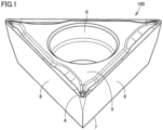
- Fig. 1 is a schematic perspective view of a configuration of a cutting insert according to the present embodiment.
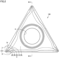
- Fig. 2 is a schematic plan view of a configuration of the cutting insert according to the present embodiment.
- Fig. 3 is a schematic cross section taken along a line III-III in Fig. 2 .
- cutting insert 100 mainly has a seating surface 7, an outer peripheral surface 8, a top surface 5, and an attachment hole 6.
- Seating surface 7 is a flat surface.
- Seating surface 7 is a surface on which cutting insert 100 is attached to a holder 70 (see Fig. 13 ).
- Outer peripheral surface 8 is contiguous to seating surface 7.
- Top surface 5 is contiguous to outer peripheral surface 8 and is opposite to seating surface 7 with outer peripheral surface 8 posed therebetween.
- Attachment hole 6 penetrates the cutting insert between top surface 5 and seating surface 7.
- Outer peripheral surface 8 surrounds attachment hole 6.
- top surface 5 has an external shape in the form of a polygon.
- a top view means that the direction in which top surface 5 is viewed is a direction perpendicular to seating surface 7 and extending from top surface 5 toward seating surface 7.
- a diagram showing a top surface of cutting insert 100 when cutting insert 100 is placed so that seating surface 7 is entirely in contact with a flat plane shows the figure of top surface 5 seen in a top view.
- the top view means viewing top surface 5 in the same direction. That is, it means that the direction in which top surface 5 is viewed is a direction perpendicular to seating surface 7 and extending from top surface 5 toward seating surface 7.
- Top surface 5 and outer peripheral surface 8 form a ridge line configuring cutting edge 4.
- top surface 5 has an external shape in the form of triangle, for example.
- the triangle has its three vertices used as cutting edge 4.
- Top surface 5 mainly has a first rake face 10, a second rake face 20, a third rake face 30, a breaker portion 40, and a flat surface 50.
- Flat surface 50 surrounds attachment hole 6.
- the external shape of top surface 5 is not limited to a triangle.
- Top surface 5 may have an external shape in the form of a square, for example.
- outer peripheral surface 8 has a tapered shape for example. Outer peripheral surface 8 is inclined for example so that it is reduced in width from top surface 5 toward seating surface 7. Attachment hole 6 is opened through top surface 5 and seating surface 7. Attachment hole 6 is a through hole. Attachment hole 6 has a larger diameter at top surface 5 than at seating surface 7.
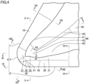
- Fig. 4 is an enlarged schematic plan view of a region IV in Fig. 2 .
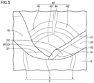
- Fig. 5 is an enlarged perspective schematic view of a region IV in Fig. 2 .
- cutting edge 4 includes a cutting corner edge portion 3 formed at one vertex of a polygon, a first cutting edge portion 1, and a second cutting edge portion 2.
- First rake face 10 is contiguous to first cutting edge portion 1.
- Second rake face 20 is contiguous to second cutting edge portion 2.
- Third rake face 30 is contiguous to cutting corner edge portion 3.
- Third rake face 30 is contiguous to each of first rake face 10 and second rake face 20.
- Third rake face 30 is located between first rake face 10 and second rake face 20.
- Outer peripheral surface 8 and first rake face 10 form a ridge line configuring first cutting edge portion 1.
- Outer peripheral surface 8 and second rake face 20 form a ridge line configuring second cutting edge portion 2.
- Outer peripheral surface 8 and third rake face 30 form a ridge line configuring cutting corner edge portion 3.
- Outer peripheral surface 8 serves as a flank. It has a clearance angle for example of 11°.
- Cutting corner edge portion 3 is curved.
- First cutting edge portion 1 is straight.
- First cutting edge portion 1 is one side of the polygon and is contiguous to one end of cutting corner edge portion 3.
- Second cutting edge portion 2 is straight.
- Second cutting edge portion 2 is another side of the polygon and is contiguous to the other end of cutting corner edge portion 3.
- Cutting corner edge portion 3 is located between first cutting edge portion 1 and second cutting edge portion 2.
- Third rake face 30 has a first region 31, a second region 32, and a third region 33.
- First region 31 is contiguous to first rake face 10.
- Second region 32 is contiguous to second rake face 20.
- Third region 33 is contiguous to second region 32.
- Third region 33 is located opposite to cutting corner edge portion 3 with second region 32 posed therebetween.
- Third region 33 is located between first region 31 and second region 32.
- second region 32 and third region 33 may form a ridge line (a first ridge line) connected to a boundary of first and second regions 31 and 32 of cutting corner edge portion 3.
- Top surface 5 has a fifth inclined surface 21 contiguous to breaker portion 40 and second rake face 20.
- Fifth inclined surface 21 is located between breaker portion 40 and second rake face 20.
- Second rake face 20 and fifth inclined surface 21 form a ridge line (a second ridge line 52) contiguous to first ridge line 51.
- Breaker portion 40 is a raised portion.
- Breaker portion 40 has a first inclined surface 41, a second inclined surface 42, a third inclined surface 43, and a fourth inclined surface 44.
- First inclined surface 41 is contiguous to first rake face 10.
- Second inclined surface 42 is contiguous to fifth inclined surface 21.
- Third inclined surface 43 is contiguous to first rake face 10, fifth inclined surface 21, first region 31, and third region 33.
- Fourth inclined surface 44 is contiguous to first inclined surface 41, second inclined surface 42, third inclined surface 43, and flat surface 50.
- Fourth inclined surface 44 is located between first inclined surface 41 and second inclined surface 42.
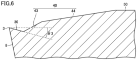
- Fig. 6 is a schematic cross section taken along the line VI-VI in Fig. 4 .
- the Fig. 6 cross section is a cross section which includes a straight line halving an angle formed by a straight line extending along first cutting edge portion 1 and a straight line extending along second cutting edge portion 2 and is also perpendicular to seating surface 7.
- third rake face 30 has a rake angle (a third rake angle ⁇ 3) which is a positive angle.
- Third rake angle ⁇ 3 is, for example, 15°.
- Third rake angle ⁇ 3 may be, for example, 10° or more and 20° or less.
- a surface having a positive angle means that the surface is inclined to have a smaller distance to seating surface 7 as the surface having the angle is farther away from cutting edge 4.
- a surface having a negative angle means that the surface is inclined to have a larger distance to seating surface 7 as the surface having the angle is farther away from cutting edge 4.
- An angle ⁇ of a surface contiguous to a point P located on cutting edge 4 is defined as follows: Initially, in the top view, a normal N is determined for a specific point P on cutting edge 4. The normal N is parallel to seating surface 7. Subsequently, a cross section including the point P and the normal N and perpendicular to seating surface 7 is determined. An angle formed in the cross section by the surface contiguous to the point P and seating surface 7 is angle ⁇ .
- the sign of the angle ⁇ that is, whether the angle ⁇ is a positive angle or a negative angle, is defined as follows: Initially, in the cross section, a direction parallel to seating surface 7 and extending from the point P toward breaker portion 40 is defined as X. Subsequently, when the surface contiguous to the point P is differentiated with respect to X, and the differential coefficient is negative, the angle ⁇ of the surface is a positive angle. In contrast, when the differential coefficient is positive, the angle ⁇ of the surface is a negative angle.
- the point P on cutting edge 4 is determined to be a single point on cutting edge 4 selected from first cutting edge portion 1, second cutting edge portion 2 or cutting corner edge portion 3.
- a broken line in the horizontal direction is a part of the normal N and is also parallel to seating surface 7.
- third inclined surface 43 is contiguous to third rake face 30.
- Third inclined surface 43 is raised to have a larger distance to seating surface 7 as third inclined surface 43 is farther away from third cutting edge portion 3.
- Fourth inclined surface 44 is contiguous to third inclined surface 43.
- Third inclined surface 43 is located between third rake face 30 and fourth inclined surface 44.
- Fourth inclined surface 44 is contiguous to flat surface 50.
- Fourth inclined surface 44 is located between third inclined surface 43 and flat surface 50.
- Flat surface 50 and third inclined surface 43 may form an angle larger than that formed by flat surface 50 and fourth inclined surface 44.
- Third inclined surface 43 and fourth inclined surface 44 each have a negative inclination angle.
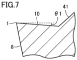
- Fig. 7 is a schematic cross section taken along the line VII-VII of Fig. 4 .
- the Fig. 7 cross section is a cross section perpendicular to first cutting edge portion 1, transverse to first inclined surface 41, and perpendicular to seating surface 7.
- first rake face 10 has a rake angle (a first rake angle ⁇ 1) which is a positive angle.
- First rake angle ⁇ 1 is, for example, 5°.
- First rake angle ⁇ 1 may for example be larger than 0° and smaller than 20°.
- First rake angle ⁇ 1 may be 15° or less, and may be 10° or less.
- First inclined surface 41 is contiguous to first rake face 10.
- First inclined surface 41 is located opposite to first cutting edge portion 1 with first rake face 10 posed therebetween. First inclined surface 41 is raised to have a larger distance to seating surface 7 as first inclined surface 41 is farther away from first cutting edge portion 1. First inclined surface 41 has a negative inclination angle.
- Fig. 8 is a schematic cross section taken along the line VIII-VIII in Fig. 4 .
- the Fig. 8 cross section is a cross section perpendicular to first cutting edge portion 1, transverse to third inclined surface 43, and perpendicular to seating surface 7.
- first rake face 10 has a rake angle (a fourth rake angle ⁇ 4) which is a positive angle.
- Fourth rake angle ⁇ 4 is, for example, 10°.
- Fourth rake angle ⁇ 4 may for example be larger than 0° and 15° or less.
- Fourth rake angle ⁇ 4 is larger than first rake angle ⁇ 1.
- First rake face 10 has a portion that changes to have a rake angle increasing as first rake surface 10 approaches third rake face 30.
- Third inclined surface 43 is contiguous to first rake face 10.
- Third inclined surface 43 is located opposite to first cutting edge portion 1 with first rake face 10 posed therebetween.
- Third inclined surface 43 has a portion raised to have a larger distance to seating surface 7 as third inclined surface 43 is farther away from first cutting edge portion 1.
- Fig. 9 is a schematic cross section taken along the line IX-IX of Fig. 4 .
- the Fig. 9 cross section is a cross section perpendicular to second cutting edge portion 2, transverse to second inclined surface 42, and perpendicular to seating surface 7.
- second rake face 20 has a rake angle (a second rake angle ⁇ 2) which is a negative angle.
- Second rake angle ⁇ 2 is, for example, - 5°.
- Second rake angle ⁇ 2 may be larger than - 10° and smaller than 0°, for example.
- Fifth inclined surface 21 is contiguous to second rake face 20.
- Fifth inclined surface 21 is located opposite to second cutting edge portion 2 with second rake face 20 posed therebetween.
- Fifth inclined surface 21 is inclined to have a smaller distance to seating surface 7 as fifth inclined surface 21 is farther away from second cutting edge portion 2.
- Second inclined surface 42 is contiguous to fifth inclined surface 21.
- Fifth inclined surface 21 is located between second rake face 20 and second inclined surface 42.
- Second inclined surface 42 is raised to have a larger distance to seating surface 7 as second inclined surface 42 is farther away from second cutting edge portion 2.
- Fifth inclined surface 21 has an inclination angle which is a positive angle.
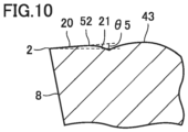
- Fig. 10 is a schematic cross section taken along the line X-X in Fig. 4 .
- the Fig. 10 cross section is a cross section perpendicular to second cutting edge portion 2, transverse to third inclined surface 43, and perpendicular to seating surface 7.
- second rake face 20 has a rake angle (a fifth rake angle ⁇ 5) which is a negative angle.
- Fifth rake angle ⁇ 5 is, for example, - 5°.
- Fifth rake angle ⁇ 5 may be larger than - 10° and smaller than 0°, for example.
- Fifth rake angle ⁇ 5 may be equal to second rake angle ⁇ 2.
- Third inclined surface 43 is contiguous to fifth inclined surface 21.
- Fifth inclined surface 21 is located between second rake face 20 and third inclined surface 43.
- Third inclined surface 43 has a portion raised so that a distance between third inclined surface 43 and seating surface 7 increases as third inclined surface 43 is farther away from second cutting edge portion 2.
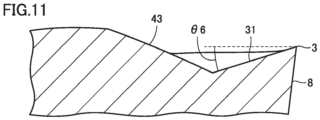
- Fig. 11 is a schematic cross section taken along the line XI-XI in Fig. 4 .
- the Fig. 11 cross section is a cross section transverse to first region 31 and third inclined surface 43 and perpendicular to seating surface 7.
- first region 31 has a rake angle (a sixth rake angle ⁇ 6) which is a positive angle.
- Sixth rake angle ⁇ 6 is, for example, 17°.
- Sixth rake angle ⁇ 6 may for example be 10° or more and 20° or less.
- Third inclined surface 43 is contiguous to first region 31.
- Third inclined surface 43 is located opposite to cutting corner edge portion 3 with first region 31 posed therebetween.
- Third inclined surface 43 is raised to have a larger distance to seating surface 7 as third inclined surface 43 is farther away from cutting corner edge portion 3.
- Third inclined surface 43 has an inclination angle which is a negative angle.
- Fig. 12 is a schematic cross section taken along the line XII-XII in Fig. 4 .
- the Fig. 12 cross section is a cross section transverse to second region 32, third region 33 and third inclined surface 43 and perpendicular to seating surface 7.
- second region 32 has a rake angle (a seventh rake angle ⁇ 7) which is a negative angle.
- Seventh rake angle ⁇ 7 is, for example, - 5.4°.
- Seventh rake angle ⁇ 7 may be larger than - 10° and smaller than 0°, for example.
- Third region 33 is contiguous to second region 32. Third region 33 is located opposite to cutting corner edge portion 3 with second region 32 posed therebetween. Third region 33 is inclined to have a smaller distance to seating surface 7 as third region 33 is farther away from cutting corner edge portion 3. In other words, third region 33 has a positive inclination angle. Third inclined surface 43 is located opposite to second region 32 with third region 33 posed therebetween. In other words, third region 33 is located between second region 32 and third inclined surface 43.
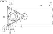
- FIG. 13 is a schematic plan view of a configuration of a boring tool according to the present embodiment.
- a boring tool 200 mainly includes cutting insert 100, holder 70, and a fastening screw 60.
- Holder 70 supports cutting insert 100.
- Holder 70 is provided with a cutting insert attachment portion 71.
- Cutting insert attachment portion 71 is a recess provided in holder 70.
- Cutting insert attachment portion 71 is provided at a front 91 of holder 70.
- Cutting insert 100 is disposed at cutting insert attachment portion 71.
- Fastening screw 60 is disposed in attachment hole 6 of cutting insert 100.
- Cutting insert 100 is fixed to holder 70 by screwing fastening screw 60 into a screw hole (not shown) provided in holder 70.
- second cutting edge portion 2 is provided along a side surface of cutting insert attachment portion 71.
- first cutting edge portion 1 is provided at front 91 of holder 70 with respect to attachment hole 6.
- Cutting insert 100 has a function and an effect as follows:
- cutting insert 100 has first rake face 10 and first region 31 each having a rake angle which is a positive angle and second rake face 20 and second region 32 each having a rake angle which is a negative angle.
- First rake face 10 and first region 31 each having a rake angle which is a positive angle allow sharpness and chip control to be maintained satisfactorily.
- Second rake face 20 and second region 32 each having a rake angle which is a negative angle allow boundary wear to be reduced.
- Cutting inserts 100 according to samples 1-1, 1-2, 1-3, 2-1, 2-2, and 2-3 were prepared.
- Cutting inserts 100 according to the samples 1-1, 1-2, and 1-3 had first rake angle ⁇ 1 set to 5°, second rake angle ⁇ 2 set to - 5°, third rake angle ⁇ 3 set to 15°, fourth rake angle ⁇ 4 set to 10°, and fifth rake angle ⁇ 5 set to - 5°.
- Cutting inserts 100 according to the samples 2-1, 2-2, and 2-3 had first rake angle ⁇ 1 set to 5°, second rake angle ⁇ 2 set to 5°, third rake angle ⁇ 3 set to 15°, fourth rake angle ⁇ 4 set to 10°, and fifth rake angle ⁇ 5 set to 10°. That is, cutting inserts 100 according to the samples 1-1, 1-2, and 1-3 and cutting inserts 100 according to the samples 2-1, 2-2, and 2-3 differ in second rake angle ⁇ 2 and fifth rake angle ⁇ 5, and have the remainder in configuration identical to that of cutting insert 100 shown in Fig. 1 .
- a boring head set manufactured by BIG DAISHOWA SEIKI CO., LTD. (model number: EWN32-60CKB3) and a shank holder manufactured by BIG DAISHOWA SEIKI CO., LTD. (model number: BT40-CK3-135) were used as a tool.
- a machining center manufactured by DMG MORI. CO. LTD. (model number: NV5000/BBT40) was used as a machine.
- the workpiece was formed of S50C.
- Cutting insert 100 was formed of non-coated cermet.
- FIG. 14 is a schematic diagram showing a state in which cutting insert 100 is used to process the workpiece for an internal diameter.
- cutting insert 100 had cutting corner edge portion 3 brought into contact with a bore surface 81 of a workpiece 80 to finish bore surface 81.
- the cutting speed (Vc) was set to 200 m/min.
- the feed rate (f) was set to 0.06 mm/rotation.
- the cutting depth was set to 0.2 mm.
- a water-soluble cutting fluid was used. Internal lubrication (2 MPa) was applied.
- the cutting length was set to 1 m.
- An arrow 92 in Fig. 14 indicates a direction in which cutting insert 100 is moved.
- a rake angle of first region 31 in a cross section taken along the line XI-XI shown in Fig. 14 (sixth rake angle ⁇ 6) is a positive angle (see Fig. 11 ).
- a rake angle of second region 32 in a cross section taken along the line XII-XII shown in Fig. 14 (seventh rake angle ⁇ 7) is a negative angle (see Fig. 12 ).
Landscapes
- Engineering & Computer Science (AREA)
- Mechanical Engineering (AREA)
- Cutting Tools, Boring Holders, And Turrets (AREA)
- Turning (AREA)
- Milling Processes (AREA)
Claims (7)
- Schneideinsatz (100), umfassend:eine Sitzfläche (7);eine Außenumfangsfläche (8), die an die Sitzfläche (7) angrenzt; undeine Oberseite (5), die an die Außenumfangsfläche (8) angrenzt und gegenüber der Sitzfläche (7) angeordnet ist, wobei die Außenumfangsfläche (8) dazwischen angeordnet ist;die Oberseite (5) eine äußere Form in Gestalt eines Polygons in einer Draufsicht hat, bei der die Oberseite (5) in einer Richtung senkrecht zu der Sitzfläche (7) betrachtet wird und sich von der Oberseite (5) zu der Sitzfläche (7) erstreckt,wobei die Oberseite (5) und die Außenumfangsfläche (8) eine Gratlinie bilden, die eine Schneidkante (4) darstellt,die Schneidkante (4) einen gekrümmten Schneideckenkantenabschnitt (3), der an einem Scheitelpunkt des Polygons ausgebildet ist, einen ersten Schneidkantenabschnitt (1), der an ein Ende des Schneideckenkantenabschnitts (3) angrenzt und sich linear erstreckt, und einen zweiten Schneidkantenabschnitt (2), der an das andere Ende des Schneideckenkantenabschnitts (3) angrenzt und sich linear erstreckt, umfasst,die Oberseite (5) eine erste Spanfläche (10), die an den ersten Schneidkantenabschnitt (1) angrenzt, eine zweite Spanfläche (20), die an den zweiten Schneidkantenabschnitt (2) angrenzt, und eine dritte Spanfläche (30) umfasst, die an den Schneideckenkantenabschnitt (3) angrenzt und zudem an die erste und zweite Spanfläche (10, 20) angrenzt,die dritte Spanfläche (30) einen ersten Bereich (31), der an die erste Spanfläche (10) angrenzt, und einen zweiten Bereich (32) hat, der an die zweite Spanfläche (20) angrenzt,die erste Spanfläche (10) und der erste Bereich (31) jeweils einen Spanwinkel haben, der ein positiver Winkel ist,die zweite Spanfläche (20) und der zweite Bereich (32) jeweils einen Spanwinkel haben, der ein negativer Winkel ist,die Oberseite (5) eine dritte geneigte Fläche (43) hat, die an die erste Spanfläche (10) angrenzt, unddie dritte geneigte Fläche (43) gegenüber dem ersten Schneidkantenabschnitt (1) angeordnet ist, wobei die erste Spanfläche (10) dazwischen angeordnet ist und einen Abschnitt hat, der erhöht ist, um einen größeren Abstand zu der Sitzfläche (7) zu haben, wenn die dritte geneigte Fläche (43) weiter von dem ersten Schneidkantenabschnitt (1) entfernt ist,dadurch gekennzeichnet, dass der Schneideinsatz zudem ein Befestigungsloch (6) umfasst, das den Schneideinsatz (100) zwischen der Oberseite (5) und der Sitzfläche (7) durchdringt, und dassdie erste Spanfläche (10) einen Abschnitt hat, der sich so verändert, dass der Spanwinkel zunimmt, wenn sich die erste Spanfläche (10) der dritten Spanfläche (30) nähert.
- Schneideinsatz (100) nach Anspruch 1, bei demdie dritte Spanfläche (30) einen dritten Bereich (33) umfasst, der an den zweiten Bereich (32) angrenzt, undder dritte Bereich (33) einen Neigungswinkel hat, der ein positiver Winkel ist.
- Schneideinsatz (100) nach Anspruch 2, bei dem in der Draufsicht der zweite Bereich (32) und der dritte Bereich (33) eine Gratlinie bilden, die mit einer Grenze zwischen dem ersten und dem zweiten Bereich (31, 32) des Schneideckenrandabschnitts (3) verbunden ist.
- Schneideinsatz (100) nach einem der Ansprüche 1 bis 3, bei dem die erste Spanfläche (10) einen Spanwinkel größer als 0° und kleiner als 20° aufweist.
- Schneideinsatz (100) nach einem der Ansprüche 1 bis 4, bei dem die zweite Spanfläche (20) einen Spanwinkel größer als - 10° und kleiner als 0° aufweist.
- Schneideinsatz (100) nach einem der Ansprüche 1 bis 5, bei dem die Oberseite (5) in der Draufsicht die äußere Form eines Dreiecks hat.
- Bohrwerkzeug (200), umfassend einen Schneideinsatz (100) nach einem der Ansprüche 1 bis 6 und einen Halter (70), der den Schneideinsatz (100) hält,wobei der Schneideinsatz (100) an einem Schneideinsatz-Befestigungsabschnitt (71) angeordnet ist, der an einer Vorderseite (91) des Halters (70) vorgesehen ist,in der Draufsicht der zweite Schneidkantenabschnitt (2) entlang einer Seitenfläche des Schneideinsatz-Befestigungsabschnitts (71) angeordnet ist und der erste Schneidkantenabschnitt (1) in Bezug auf das Befestigungsloch (6) an der Vorderseite (91) angeordnet ist.
Applications Claiming Priority (2)
| Application Number | Priority Date | Filing Date | Title |
|---|---|---|---|
| JP2018192619 | 2018-10-11 | ||
| PCT/JP2019/036128 WO2020075445A1 (ja) | 2018-10-11 | 2019-09-13 | 切削インサートおよび内径切削用工具 |
Publications (3)
| Publication Number | Publication Date |
|---|---|
| EP3865232A1 EP3865232A1 (de) | 2021-08-18 |
| EP3865232A4 EP3865232A4 (de) | 2022-07-27 |
| EP3865232B1 true EP3865232B1 (de) | 2024-09-18 |
Family
ID=70164558
Family Applications (1)
| Application Number | Title | Priority Date | Filing Date |
|---|---|---|---|
| EP19870746.5A Active EP3865232B1 (de) | 2018-10-11 | 2019-09-13 | Schneideinsatz und innendurchmesser-schneidwerkzeug |
Country Status (6)
| Country | Link |
|---|---|
| US (1) | US11040404B2 (de) |
| EP (1) | EP3865232B1 (de) |
| JP (1) | JP6799285B2 (de) |
| CN (1) | CN112805110B (de) |
| TW (1) | TWI798495B (de) |
| WO (1) | WO2020075445A1 (de) |
Families Citing this family (4)
| Publication number | Priority date | Publication date | Assignee | Title |
|---|---|---|---|---|
| US11446745B2 (en) * | 2018-09-27 | 2022-09-20 | Iscar, Ltd. | Turning insert having peninsula and island protrusions, and turning tool |
| US11819927B2 (en) * | 2021-06-11 | 2023-11-21 | Taegutec Ltd. | Cutting insert and cutting tool assembly including same |
| USD1082874S1 (en) * | 2022-04-05 | 2025-07-08 | Sumitomo Electric Hardmetal Corp. | Cutting tool |
| CN117921044A (zh) * | 2024-03-25 | 2024-04-26 | 赣州澳克泰工具技术有限公司 | 一种可转位切削刀片和切削刀具 |
Family Cites Families (23)
| Publication number | Priority date | Publication date | Assignee | Title |
|---|---|---|---|---|
| JPH0128961Y2 (de) * | 1985-03-04 | 1989-09-04 | ||
| JPH0574708U (ja) * | 1992-03-25 | 1993-10-12 | 三菱マテリアル株式会社 | スローアウェイチップ |
| IL103008A (en) * | 1992-09-01 | 1996-12-05 | Iscar Ltd | Cutting insert for a milling cutter tool |
| SE500719C2 (sv) * | 1993-01-27 | 1994-08-15 | Sandvik Ab | Skär med skruvformigt vriden spånyta |
| IL110785A (en) * | 1994-08-25 | 1998-04-05 | Iscar Ltd | Cutting insert for a rotary milling cutter |
| JPH09290312A (ja) * | 1996-04-26 | 1997-11-11 | Mitsubishi Materials Corp | スローアウェイチップおよびスローアウェイ式穴明け工具 |
| IL118797A (en) * | 1996-07-05 | 1999-10-28 | Iscar Ltd | Cutting insert |
| JPH11197909A (ja) * | 1998-01-19 | 1999-07-27 | Mitsubishi Materials Corp | スローアウェイチップ |
| JP3483859B2 (ja) | 2001-03-06 | 2004-01-06 | オーエスジー株式会社 | スローアウェイ式チップ、及び、そのスローアウェイ式チップが装着されるフライス工具 |
| JP4678095B2 (ja) * | 2001-04-16 | 2011-04-27 | 株式会社タンガロイ | スローアウェイ式ドリル用の切刃チップ |
| US6742970B2 (en) * | 2002-06-12 | 2004-06-01 | Kennametal Inc. | Cutting tool |
| DE202004002491U1 (de) * | 2004-02-17 | 2005-08-18 | Kennametal Inc. | Schneidplatte, insbesondere für ein Ausdrehwerkzeug |
| SE530780C2 (sv) | 2006-01-10 | 2008-09-09 | Sandvik Intellectual Property | Indexerbart skär med olika släppningsvinklar samt svarvverktyg |
| EP2258504B1 (de) * | 2008-03-31 | 2017-10-04 | Mitsubishi Materials Corporation | Schaftfräser und schneideeinsatz dafür |
| JP5309820B2 (ja) * | 2008-09-12 | 2013-10-09 | 三菱マテリアル株式会社 | 切削インサートおよびインサート着脱式転削工具 |
| EP2446992B1 (de) * | 2009-06-26 | 2017-09-20 | Kyocera Corporation | Schneideeinsatz, schneidewerkzeug sowie herstellungsverfahren für schneideprodukte damit |
| JP5853613B2 (ja) * | 2010-11-15 | 2016-02-09 | 三菱マテリアル株式会社 | 切削インサート |
| EP2492035B1 (de) * | 2011-02-24 | 2016-01-13 | Seco Tools AB | Achteckiger Schneideinsatz mit Kantenabschnitt mit variablem Keilwinkel und Schneidwerkzeug |
| WO2015037617A1 (ja) * | 2013-09-11 | 2015-03-19 | 日立ツール株式会社 | 刃先交換式回転切削工具及びそれに用いるインサート |
| US10232445B2 (en) * | 2014-02-26 | 2019-03-19 | Kyocera Corporation | Cutting insert, cutting tool, and method for manufacturing machined product |
| US10688570B2 (en) * | 2016-02-12 | 2020-06-23 | Mitsubishi Hitachi Tool Engineering, Ltd. | Indexable rotary cutting tool and insert |
| US11179785B2 (en) * | 2016-12-09 | 2021-11-23 | Moldino Tool Engineering, Ltd. | Cutting insert and indexable edge rotary cutting tool |
| JP6626938B2 (ja) | 2018-08-23 | 2019-12-25 | 株式会社高井製作所 | 豆腐の切断装置及び豆腐のパック詰め装置 |
-
2019
- 2019-09-13 EP EP19870746.5A patent/EP3865232B1/de active Active
- 2019-09-13 CN CN201980066761.8A patent/CN112805110B/zh active Active
- 2019-09-13 US US16/957,902 patent/US11040404B2/en active Active
- 2019-09-13 JP JP2020533865A patent/JP6799285B2/ja active Active
- 2019-09-13 WO PCT/JP2019/036128 patent/WO2020075445A1/ja not_active Ceased
- 2019-10-07 TW TW108136237A patent/TWI798495B/zh active
Also Published As
| Publication number | Publication date |
|---|---|
| TW202026122A (zh) | 2020-07-16 |
| WO2020075445A1 (ja) | 2020-04-16 |
| US20200406368A1 (en) | 2020-12-31 |
| US11040404B2 (en) | 2021-06-22 |
| JPWO2020075445A1 (ja) | 2021-02-15 |
| JP6799285B2 (ja) | 2020-12-16 |
| CN112805110A (zh) | 2021-05-14 |
| TWI798495B (zh) | 2023-04-11 |
| CN112805110B (zh) | 2023-07-14 |
| EP3865232A1 (de) | 2021-08-18 |
| EP3865232A4 (de) | 2022-07-27 |
Similar Documents
| Publication | Publication Date | Title |
|---|---|---|
| EP3865232B1 (de) | Schneideinsatz und innendurchmesser-schneidwerkzeug | |
| EP3150317B1 (de) | Schneideinsatz und fräswerkzeug | |
| EP1575728B1 (de) | Werkzeugeinsatz und werkzeug | |
| EP1931487B1 (de) | Fräsplatte | |
| EP3351328B1 (de) | Schneideinsatz und schneidwerkzeug mit auswechselbarer klinge | |
| EP3006140B1 (de) | Dreheinsatz und Drehwerkzeug | |
| US9744597B2 (en) | Cutting tool insert and cutting tool insert holder | |
| EP2576113B1 (de) | Fräswerkzeug und schneideeinsatz | |
| EP3677368B1 (de) | Schneideinsatz und kugelfräser mit austauschbarem schneideinsatz | |
| EP3450065A1 (de) | Schneideinsatz | |
| EP3612334B1 (de) | Rampeneinsatz mit nicht-positiver schneidgeometrie und rampenwerkzeug | |
| EP2832482A1 (de) | Schneidwerkzeug mit auswechselbarem kopf | |
| WO2020196597A1 (ja) | 切削工具用ボディ、切削インサートおよび切削工具 | |
| EP3512656B1 (de) | Schneidwerkzeug mit einer wendeschneidplatte | |
| EP1355755B1 (de) | Schneidwerkzeug und schneideinsätze | |
| US11534838B1 (en) | Indexable lay-down cutting insert having a central body portion and three circumferentially spaced cutting portions, and cutting tool | |
| CA3057000C (en) | Ramping insert having non-positive cutting geometry and ramping tool |
Legal Events
| Date | Code | Title | Description |
|---|---|---|---|
| STAA | Information on the status of an ep patent application or granted ep patent |
Free format text: STATUS: THE INTERNATIONAL PUBLICATION HAS BEEN MADE |
|
| PUAI | Public reference made under article 153(3) epc to a published international application that has entered the european phase |
Free format text: ORIGINAL CODE: 0009012 |
|
| STAA | Information on the status of an ep patent application or granted ep patent |
Free format text: STATUS: REQUEST FOR EXAMINATION WAS MADE |
|
| 17P | Request for examination filed |
Effective date: 20210325 |
|
| AK | Designated contracting states |
Kind code of ref document: A1 Designated state(s): AL AT BE BG CH CY CZ DE DK EE ES FI FR GB GR HR HU IE IS IT LI LT LU LV MC MK MT NL NO PL PT RO RS SE SI SK SM TR |
|
| DAV | Request for validation of the european patent (deleted) | ||
| DAX | Request for extension of the european patent (deleted) | ||
| A4 | Supplementary search report drawn up and despatched |
Effective date: 20220624 |
|
| RIC1 | Information provided on ipc code assigned before grant |
Ipc: B23B 29/04 20060101ALI20220620BHEP Ipc: B23B 27/14 20060101AFI20220620BHEP |
|
| STAA | Information on the status of an ep patent application or granted ep patent |
Free format text: STATUS: EXAMINATION IS IN PROGRESS |
|
| 17Q | First examination report despatched |
Effective date: 20230222 |
|
| GRAP | Despatch of communication of intention to grant a patent |
Free format text: ORIGINAL CODE: EPIDOSNIGR1 |
|
| STAA | Information on the status of an ep patent application or granted ep patent |
Free format text: STATUS: GRANT OF PATENT IS INTENDED |
|
| INTG | Intention to grant announced |
Effective date: 20240424 |
|
| GRAS | Grant fee paid |
Free format text: ORIGINAL CODE: EPIDOSNIGR3 |
|
| GRAA | (expected) grant |
Free format text: ORIGINAL CODE: 0009210 |
|
| STAA | Information on the status of an ep patent application or granted ep patent |
Free format text: STATUS: THE PATENT HAS BEEN GRANTED |
|
| AK | Designated contracting states |
Kind code of ref document: B1 Designated state(s): AL AT BE BG CH CY CZ DE DK EE ES FI FR GB GR HR HU IE IS IT LI LT LU LV MC MK MT NL NO PL PT RO RS SE SI SK SM TR |
|
| REG | Reference to a national code |
Ref country code: GB Ref legal event code: FG4D |
|
| REG | Reference to a national code |
Ref country code: CH Ref legal event code: EP |
|
| P01 | Opt-out of the competence of the unified patent court (upc) registered |
Free format text: CASE NUMBER: APP_48268/2024 Effective date: 20240822 |
|
| REG | Reference to a national code |
Ref country code: IE Ref legal event code: FG4D |
|
| REG | Reference to a national code |
Ref country code: DE Ref legal event code: R096 Ref document number: 602019059241 Country of ref document: DE |
|
| REG | Reference to a national code |
Ref country code: LT Ref legal event code: MG9D |
|
| PG25 | Lapsed in a contracting state [announced via postgrant information from national office to epo] |
Ref country code: NO Free format text: LAPSE BECAUSE OF FAILURE TO SUBMIT A TRANSLATION OF THE DESCRIPTION OR TO PAY THE FEE WITHIN THE PRESCRIBED TIME-LIMIT Effective date: 20241218 |
|
| PG25 | Lapsed in a contracting state [announced via postgrant information from national office to epo] |
Ref country code: GR Free format text: LAPSE BECAUSE OF FAILURE TO SUBMIT A TRANSLATION OF THE DESCRIPTION OR TO PAY THE FEE WITHIN THE PRESCRIBED TIME-LIMIT Effective date: 20241219 Ref country code: FI Free format text: LAPSE BECAUSE OF FAILURE TO SUBMIT A TRANSLATION OF THE DESCRIPTION OR TO PAY THE FEE WITHIN THE PRESCRIBED TIME-LIMIT Effective date: 20240918 |
|
| PG25 | Lapsed in a contracting state [announced via postgrant information from national office to epo] |
Ref country code: BG Free format text: LAPSE BECAUSE OF FAILURE TO SUBMIT A TRANSLATION OF THE DESCRIPTION OR TO PAY THE FEE WITHIN THE PRESCRIBED TIME-LIMIT Effective date: 20240918 |
|
| PG25 | Lapsed in a contracting state [announced via postgrant information from national office to epo] |
Ref country code: LV Free format text: LAPSE BECAUSE OF FAILURE TO SUBMIT A TRANSLATION OF THE DESCRIPTION OR TO PAY THE FEE WITHIN THE PRESCRIBED TIME-LIMIT Effective date: 20240918 |
|
| PG25 | Lapsed in a contracting state [announced via postgrant information from national office to epo] |
Ref country code: HR Free format text: LAPSE BECAUSE OF FAILURE TO SUBMIT A TRANSLATION OF THE DESCRIPTION OR TO PAY THE FEE WITHIN THE PRESCRIBED TIME-LIMIT Effective date: 20240918 |
|
| REG | Reference to a national code |
Ref country code: NL Ref legal event code: MP Effective date: 20240918 |
|
| PG25 | Lapsed in a contracting state [announced via postgrant information from national office to epo] |
Ref country code: RS Free format text: LAPSE BECAUSE OF FAILURE TO SUBMIT A TRANSLATION OF THE DESCRIPTION OR TO PAY THE FEE WITHIN THE PRESCRIBED TIME-LIMIT Effective date: 20241218 |
|
| PG25 | Lapsed in a contracting state [announced via postgrant information from national office to epo] |
Ref country code: RS Free format text: LAPSE BECAUSE OF FAILURE TO SUBMIT A TRANSLATION OF THE DESCRIPTION OR TO PAY THE FEE WITHIN THE PRESCRIBED TIME-LIMIT Effective date: 20241218 Ref country code: NO Free format text: LAPSE BECAUSE OF FAILURE TO SUBMIT A TRANSLATION OF THE DESCRIPTION OR TO PAY THE FEE WITHIN THE PRESCRIBED TIME-LIMIT Effective date: 20241218 Ref country code: LV Free format text: LAPSE BECAUSE OF FAILURE TO SUBMIT A TRANSLATION OF THE DESCRIPTION OR TO PAY THE FEE WITHIN THE PRESCRIBED TIME-LIMIT Effective date: 20240918 Ref country code: HR Free format text: LAPSE BECAUSE OF FAILURE TO SUBMIT A TRANSLATION OF THE DESCRIPTION OR TO PAY THE FEE WITHIN THE PRESCRIBED TIME-LIMIT Effective date: 20240918 Ref country code: GR Free format text: LAPSE BECAUSE OF FAILURE TO SUBMIT A TRANSLATION OF THE DESCRIPTION OR TO PAY THE FEE WITHIN THE PRESCRIBED TIME-LIMIT Effective date: 20241219 Ref country code: FI Free format text: LAPSE BECAUSE OF FAILURE TO SUBMIT A TRANSLATION OF THE DESCRIPTION OR TO PAY THE FEE WITHIN THE PRESCRIBED TIME-LIMIT Effective date: 20240918 Ref country code: BG Free format text: LAPSE BECAUSE OF FAILURE TO SUBMIT A TRANSLATION OF THE DESCRIPTION OR TO PAY THE FEE WITHIN THE PRESCRIBED TIME-LIMIT Effective date: 20240918 |
|
| REG | Reference to a national code |
Ref country code: AT Ref legal event code: MK05 Ref document number: 1724261 Country of ref document: AT Kind code of ref document: T Effective date: 20240918 |
|
| PG25 | Lapsed in a contracting state [announced via postgrant information from national office to epo] |
Ref country code: NL Free format text: LAPSE BECAUSE OF FAILURE TO SUBMIT A TRANSLATION OF THE DESCRIPTION OR TO PAY THE FEE WITHIN THE PRESCRIBED TIME-LIMIT Effective date: 20240918 |
|
| PG25 | Lapsed in a contracting state [announced via postgrant information from national office to epo] |
Ref country code: IS Free format text: LAPSE BECAUSE OF FAILURE TO SUBMIT A TRANSLATION OF THE DESCRIPTION OR TO PAY THE FEE WITHIN THE PRESCRIBED TIME-LIMIT Effective date: 20250118 Ref country code: PT Free format text: LAPSE BECAUSE OF FAILURE TO SUBMIT A TRANSLATION OF THE DESCRIPTION OR TO PAY THE FEE WITHIN THE PRESCRIBED TIME-LIMIT Effective date: 20250120 |
|
| PG25 | Lapsed in a contracting state [announced via postgrant information from national office to epo] |
Ref country code: RO Free format text: LAPSE BECAUSE OF FAILURE TO SUBMIT A TRANSLATION OF THE DESCRIPTION OR TO PAY THE FEE WITHIN THE PRESCRIBED TIME-LIMIT Effective date: 20240918 Ref country code: SM Free format text: LAPSE BECAUSE OF FAILURE TO SUBMIT A TRANSLATION OF THE DESCRIPTION OR TO PAY THE FEE WITHIN THE PRESCRIBED TIME-LIMIT Effective date: 20240918 |
|
| PG25 | Lapsed in a contracting state [announced via postgrant information from national office to epo] |
Ref country code: ES Free format text: LAPSE BECAUSE OF FAILURE TO SUBMIT A TRANSLATION OF THE DESCRIPTION OR TO PAY THE FEE WITHIN THE PRESCRIBED TIME-LIMIT Effective date: 20240918 |
|
| PG25 | Lapsed in a contracting state [announced via postgrant information from national office to epo] |
Ref country code: EE Free format text: LAPSE BECAUSE OF FAILURE TO SUBMIT A TRANSLATION OF THE DESCRIPTION OR TO PAY THE FEE WITHIN THE PRESCRIBED TIME-LIMIT Effective date: 20240918 Ref country code: AT Free format text: LAPSE BECAUSE OF FAILURE TO SUBMIT A TRANSLATION OF THE DESCRIPTION OR TO PAY THE FEE WITHIN THE PRESCRIBED TIME-LIMIT Effective date: 20240918 |
|
| PG25 | Lapsed in a contracting state [announced via postgrant information from national office to epo] |
Ref country code: PL Free format text: LAPSE BECAUSE OF FAILURE TO SUBMIT A TRANSLATION OF THE DESCRIPTION OR TO PAY THE FEE WITHIN THE PRESCRIBED TIME-LIMIT Effective date: 20240918 Ref country code: CZ Free format text: LAPSE BECAUSE OF FAILURE TO SUBMIT A TRANSLATION OF THE DESCRIPTION OR TO PAY THE FEE WITHIN THE PRESCRIBED TIME-LIMIT Effective date: 20240918 |
|
| PG25 | Lapsed in a contracting state [announced via postgrant information from national office to epo] |
Ref country code: IT Free format text: LAPSE BECAUSE OF FAILURE TO SUBMIT A TRANSLATION OF THE DESCRIPTION OR TO PAY THE FEE WITHIN THE PRESCRIBED TIME-LIMIT Effective date: 20240918 Ref country code: SK Free format text: LAPSE BECAUSE OF FAILURE TO SUBMIT A TRANSLATION OF THE DESCRIPTION OR TO PAY THE FEE WITHIN THE PRESCRIBED TIME-LIMIT Effective date: 20240918 |
|
| REG | Reference to a national code |
Ref country code: DE Ref legal event code: R097 Ref document number: 602019059241 Country of ref document: DE |
|
| PG25 | Lapsed in a contracting state [announced via postgrant information from national office to epo] |
Ref country code: DK Free format text: LAPSE BECAUSE OF FAILURE TO SUBMIT A TRANSLATION OF THE DESCRIPTION OR TO PAY THE FEE WITHIN THE PRESCRIBED TIME-LIMIT Effective date: 20240918 |
|
| PLBE | No opposition filed within time limit |
Free format text: ORIGINAL CODE: 0009261 |
|
| STAA | Information on the status of an ep patent application or granted ep patent |
Free format text: STATUS: NO OPPOSITION FILED WITHIN TIME LIMIT |
|
| 26N | No opposition filed |
Effective date: 20250619 |
|
| PG25 | Lapsed in a contracting state [announced via postgrant information from national office to epo] |
Ref country code: SE Free format text: LAPSE BECAUSE OF FAILURE TO SUBMIT A TRANSLATION OF THE DESCRIPTION OR TO PAY THE FEE WITHIN THE PRESCRIBED TIME-LIMIT Effective date: 20240918 |
|
| REG | Reference to a national code |
Ref country code: CH Ref legal event code: U11 Free format text: ST27 STATUS EVENT CODE: U-0-0-U10-U11 (AS PROVIDED BY THE NATIONAL OFFICE) Effective date: 20251001 |
|
| PGFP | Annual fee paid to national office [announced via postgrant information from national office to epo] |
Ref country code: DE Payment date: 20250730 Year of fee payment: 7 |
|
| PGFP | Annual fee paid to national office [announced via postgrant information from national office to epo] |
Ref country code: CH Payment date: 20251001 Year of fee payment: 7 |