EP3862494A1 - Bouche d'incendie - Google Patents
Bouche d'incendie Download PDFInfo
- Publication number
- EP3862494A1 EP3862494A1 EP21154784.9A EP21154784A EP3862494A1 EP 3862494 A1 EP3862494 A1 EP 3862494A1 EP 21154784 A EP21154784 A EP 21154784A EP 3862494 A1 EP3862494 A1 EP 3862494A1
- Authority
- EP
- European Patent Office
- Prior art keywords
- shut
- line
- riser pipe
- rotation
- axis
- Prior art date
- Legal status (The legal status is an assumption and is not a legal conclusion. Google has not performed a legal analysis and makes no representation as to the accuracy of the status listed.)
- Granted
Links
- 239000007788 liquid Substances 0.000 claims abstract description 65
- 230000005540 biological transmission Effects 0.000 claims description 15
- 238000010276 construction Methods 0.000 description 5
- 230000001174 ascending effect Effects 0.000 description 4
- 230000008878 coupling Effects 0.000 description 4
- 238000010168 coupling process Methods 0.000 description 4
- 238000005859 coupling reaction Methods 0.000 description 4
- 238000007789 sealing Methods 0.000 description 3
- 238000006073 displacement reaction Methods 0.000 description 2
- 230000000694 effects Effects 0.000 description 2
- 230000009969 flowable effect Effects 0.000 description 2
- 239000012530 fluid Substances 0.000 description 2
- XLYOFNOQVPJJNP-UHFFFAOYSA-N water Substances O XLYOFNOQVPJJNP-UHFFFAOYSA-N 0.000 description 2
- 238000000418 atomic force spectrum Methods 0.000 description 1
- 239000006260 foam Substances 0.000 description 1
- 238000004519 manufacturing process Methods 0.000 description 1
- 230000001681 protective effect Effects 0.000 description 1
- 230000001105 regulatory effect Effects 0.000 description 1
- 230000035939 shock Effects 0.000 description 1
- 239000000126 substance Substances 0.000 description 1
- 239000000725 suspension Substances 0.000 description 1
Images


Classifications
-
- E—FIXED CONSTRUCTIONS
- E03—WATER SUPPLY; SEWERAGE
- E03B—INSTALLATIONS OR METHODS FOR OBTAINING, COLLECTING, OR DISTRIBUTING WATER
- E03B9/00—Methods or installations for drawing-off water
- E03B9/02—Hydrants; Arrangements of valves therein; Keys for hydrants
- E03B9/14—Draining devices for hydrants
-
- E—FIXED CONSTRUCTIONS
- E03—WATER SUPPLY; SEWERAGE
- E03B—INSTALLATIONS OR METHODS FOR OBTAINING, COLLECTING, OR DISTRIBUTING WATER
- E03B9/00—Methods or installations for drawing-off water
- E03B9/02—Hydrants; Arrangements of valves therein; Keys for hydrants
- E03B9/04—Column hydrants
-
- E—FIXED CONSTRUCTIONS
- E03—WATER SUPPLY; SEWERAGE
- E03B—INSTALLATIONS OR METHODS FOR OBTAINING, COLLECTING, OR DISTRIBUTING WATER
- E03B9/00—Methods or installations for drawing-off water
- E03B9/02—Hydrants; Arrangements of valves therein; Keys for hydrants
-
- E—FIXED CONSTRUCTIONS
- E03—WATER SUPPLY; SEWERAGE
- E03B—INSTALLATIONS OR METHODS FOR OBTAINING, COLLECTING, OR DISTRIBUTING WATER
- E03B9/00—Methods or installations for drawing-off water
- E03B9/02—Hydrants; Arrangements of valves therein; Keys for hydrants
- E03B9/025—Taps specially designed for outdoor use, e.g. wall hydrants, sill cocks
- E03B9/027—Taps specially designed for outdoor use, e.g. wall hydrants, sill cocks with features preventing frost damage
-
- E—FIXED CONSTRUCTIONS
- E03—WATER SUPPLY; SEWERAGE
- E03B—INSTALLATIONS OR METHODS FOR OBTAINING, COLLECTING, OR DISTRIBUTING WATER
- E03B9/00—Methods or installations for drawing-off water
- E03B9/02—Hydrants; Arrangements of valves therein; Keys for hydrants
- E03B2009/022—Hydrants with a tubular valve seat
Definitions
- the invention relates to a hydrant according to the preamble of the independent claim.
- Hydrants are usually used to provide access to a pipe for liquids laid in the ground, in particular a water pipe.
- conventional hydrants each include a riser pipe that extends from the underground liquid line to the surface and, as a rule, also to a certain operating height.
- hydrants corresponding to the prior art comprise a shut-off device, such as a piston valve, which can be operated via an actuating element.
- a shut-off device such as a piston valve
- Conventional shut-off devices are usually operated in such a way that a shut-off element is moved against the liquid pressure and pressed onto a valve seat. Overcoming the forces emanating from the fluid pressure makes operation more difficult.
- the valve seat and the The sealing element is excessively stressed, which reduces the service life of these elements.
- hydrants it is necessary to ensure a seal over a long period of time, which can also be problematic when valve seats are under pressure.
- Conventional hydrants also have a drain line that allows the riser pipe to be drained when the fluid supply is shut off. This in particular to prevent the liquid or ice remaining in the riser pipe from damaging the hydrant.
- Liquids in the context of the invention are in particular liquid substances such as water, flowable suspensions, flowable foams or the like.
- the object of the invention is now to provide a hydrant, the operability and safety of which is improved compared to conventional hydrants.
- the shut-off element is rotatably mounted about an axis of rotation, that the shut-off element optionally has a first rotary position in which the liquid supply from the liquid line into the riser is closed by the shut-off element and the drainage line is open, and that the shut-off element optionally has a has second rotational position in which the Liquid supply from the liquid line into the riser is opened through the shut-off element and the drainage line is closed.
- the emptying line is closed by the shut-off element in the second rotary position, and in particular that the emptying line is released by the shut-off element in the first rotary position.
- shut-off element follows, at least in sections, a surface in the form of a rotational body, the axis of rotation of which runs concentrically with the axis of rotation.
- the shut-off element is cylindrical and / or bell-shaped, that the shut-off element has at least one passage opening in its jacket for opening the liquid supply and a continuous area for closing the liquid supply.
- the shut-off element has at least one clearance for opening the drainage line and a continuous area for closing the drainage line, and in particular that the clearance for opening the drainage line and the continuous area for closing the drainage line is provided in the jacket or part of the Coat is.
- a feed line to be provided for feeding the liquid into the riser pipe, for the feed line to extend into the riser pipe in the shape of a connector, for the feed line, in particular its lateral surface, to have a feed opening, and for the feed opening to pass through in the first rotational position of the shut-off element the shut-off element is closed, in particular by the continuous area for closing the liquid supply.
- a feed line is provided for feeding the liquid into the riser pipe.
- the supply line extends into the riser pipe in the shape of a connector.
- the feed line in particular in its jacket surface, has a feed opening.
- the through-opening of the shut-off element and the feed opening are positioned relative to one another in the second rotational position of the shut-off element in such a way that the liquid feed into the riser pipe is opened.
- the actuating element is rotatably coupled to the shut-off element via a gear and in particular also via a shaft.
- the transmission has a reduction ratio by which, when the actuating element is rotated through an actuating angle, the shut-off element is rotated through a shut-off angle which is smaller than the actuation angle.
- the reduction is between 1:10 and 1:50, preferably 1:40.
- the transmission includes at least one gate.
- the transmission comprises a scanning element which is in operative contact with the link.
- the transmission includes a spindle drive for moving the scanning element along the axis of rotation.
- the link runs obliquely and / or helically to the axis of rotation.
- the scanning element is mounted in such a way that it is pivoted about the axis of rotation (6) when it moves along the axis of rotation and along the link.
- the scanning element for actuating the shut-off device is rotatably connected or rotatably coupled to the shut-off element.
- the link is designed as an inclined or helical groove arranged in a sleeve, and that in particular several such grooves are provided in the sleeve, which rotate the scanning elements about the axis of rotation when the scanning element moves along the axis of rotation.
- the shaft has a variable length and, in particular, is designed to be telescopic.
- the riser pipe has a variable length and, in particular, is designed to be telescopic.
- shut-off element is preferably a rotatably mounted shut-off element which at least in sections follows a surface in the form of a rotational body, the axis of rotation of the surface running concentrically with the axis of rotation of the movement of the shut-off element.
- this form of the shut-off device means that the shut-off element moves essentially normal to the direction of flow of the exiting liquid. In this way, the forces required to shut off can be reduced.
- the liquid pressure preferably acts normal to the direction of movement of the shut-off element, in particular to the only degree of freedom of the shut-off element, so that these forces are not in or against the Direction of movement of the shut-off element but essentially normal to this. This improves the operability when opening and closing on the one hand, but also improves the reliability of the shut-off on the other hand.
- the shut-off element of the shut-off device has at least two rotary positions into which it can be moved as required. In a first rotary position, the liquid supply from the liquid line into the riser pipe is closed by the shut-off element. In the second rotary position, the liquid supply from the liquid line into the riser pipe is open. In addition, there is optionally also at least one intermediate position between the first and the second rotary position, in which an opening only takes place partially, with which, for example, the flow rate or the volume flow can be regulated.
- the hydrant comprises a supply line which, for example, has a tubular, round cross section and protrudes into the riser pipe in the shape of a nozzle.
- the feed line comprises a feed opening which, for example, penetrates the jacket of the feed line.
- the supply line is preferably tubular with a round tube cross-section, the supply opening being designed as a through opening running through the jacket of the tube.
- the shut-off element can, for example, be in the form of a body of revolution, hollow cylindrical, tubular, ring-shaped or bell-shaped and encompass the supply line from the outside or also be arranged inside the supply line. Because the shut-off element has a through opening and a continuous area in its jacket, the liquid supply can be opened or closed by rotating the shut-off element.
- the feed opening is closed by the continuous area of the shut-off element. If the shut-off element is rotated from this first rotational position, then in an intermediate position the passage opening and the supply opening first overlap, which in turn leads to an overlap a certain volume flow of liquid can enter the riser pipe. If the shut-off element is moved further, the intersection of the passage opening and the supply opening becomes larger and larger, which also increases the volume flow entering.
- the through opening of the shut-off element is preferably above or concentric to the feed opening of the feed line.
- the drain line is also actuated by actuating the shut-off element.
- the shut-off element preferably has an opening for opening the drainage line and a continuous area for closing the drainage line.
- the emptying line is preferably arranged in the lower region of the ascending pipe in order to enable emptying, in particular complete emptying, of the ascending pipe.
- shut-off elements are preferably arranged on the shut-off element in such a way that the emptying line is closed when the liquid supply into the riser pipe is open, and that the emptying line is open when the liquid supply into the riser pipe is closed. As a result, the riser pipe can be automatically emptied when the supply of liquid is stopped.
- the actuating element is preferably coupled to the shut-off element via a transmission.
- a transmission is arranged along the force or torque curve acting from the actuating element to the shut-off element.
- one or more shafts or other elements such as, for example, couplings, telescopic connections and / or plug connections, can also be provided in addition to a transmission.
- the transmission preferably has a reduction. This means that when the operating element is rotated through a certain operating angle, the Shut-off element is rotated by a shut-off angle, the shut-off angle, however, being smaller than the actuation angle.
- An exemplary reduction is 1:40. This means that when the actuating element is rotated ten times, the shut-off element is rotated by a quarter of a turn, that is to say by 90 °.
- shut-off element In order to move the shut-off element from the first rotational position into the second rotational position, it is preferable for the shut-off element to pivot through 90 °. According to further embodiments, pivoting from the first rotational position into the second rotational position can be approximately 45 °, approximately 90 ° or approximately 180 °.
- An exemplary transmission includes a spindle drive, a gate and a sensing element.
- a spindle can be driven by the actuating element, by means of which a link is displaced linearly and in particular translationally along the axis of rotation.
- the backdrop is, for example, an obliquely or helically extending groove or an obliquely or helically extending web which is provided, for example, in the inside of a sleeve.
- this transmission comprises at least one scanning element which is in operative contact with the link in such a way that it is pivoted about or about an axis of rotation when the link is displaced.
- the pivoting of the scanning element takes place to a very limited extent in comparison to the actuation of the actuating element, which is due to the reduction.
- the sensing element is then coupled to the shut-off element, so that when the sensing element is rotated / pivoted, the shut-off element is also rotated / pivoted.
- the scanning element when the actuating element is rotated, the scanning element can be moved along the axis of rotation via the spindle drive.
- the link and / or the sleeve preferably remain rigid or immobile. If the scanning element is displaced along the axis of rotation, the scanning elements are moved along the backdrop and / or guided. Since the link is arranged helically or at an angle, this results in a pivoting or rotation of the scanning element or the scanning elements. This pivoting is then transmitted to the shut-off element, the transmission preferably taking place via a shaft.
- the shaft or at least one shaft of the hydrant is adjustable in length and, in particular, designed to be telescopic.
- the shaft is preferably provided between the scanning element and the shut-off element and preferably rigidly couples the shut-off element to the scanning element.
- this construction can also make the riser pipe adjustable in length, with the length of the shaft changing automatically or automatically when the riser pipe is adjusted in length.
- the riser pipe can be designed in several parts for this purpose, one part being arranged so as to be displaceable relative to the other part along the axis of rotation.
- the shift can be made possible, for example, via a screw connection.
- the length adjustment is preferably carried out along the axis of rotation
- the liquid column does not have to be compressed or displaced in order to shut off the liquid supply. Rather, in the construction according to the invention, the shut-off takes place without a change in volume and, to put it simply, by cutting off the flow of liquid.
- the riser pipe can be adjusted in length, it is possible to flexibly adapt the hydrant to the position of the underground liquid line on the one hand and to to carry out the earth level.
- two sections of the riser pipe are telescopically connected to one another via a thread.
- the outer pipe preferably remains fixed, which also enables a subsequent height adjustment without the hydrant having to be dug to the ground.
- the length of the internal shaft automatically adapts to the change in length without the system having to be dismantled or excavated.
- the segment design of the rack-like thread segments reduces the frictional forces and also the necessary manufacturing accuracy, so that the system can easily be locked or actuated with hand tools even after long periods of inactivity.
- the configuration according to the invention preferably enables a lubricant-free mechanism for actuating the hydrant.
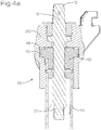
- FIGS. 4a and 4b show sectional views of an exemplary transmission in two different positions.
- the reference symbols correspond to the following components: Riser pipe 1, shut-off device 2, shut-off element 3, drain line 4, actuating element 5, axis of rotation 6, surface 7 in the form of a rotational body, jacket 8, through opening 9, continuous area (to close the liquid supply) 10, clearance 11, continuous area (to close the drain line) 12 , Feed line 13, feed opening 14, gear 15, shaft 16, spindle drive 17, gate 18, scanning element 19, sleeve 20, adjusting thread 21.
- Fig. 1 shows a sectional representation of an embodiment of a hydrant according to the invention, the representation being interrupted at two points so that relevant components can be represented without the full length of the hydrant having to be mapped.
- the hydrant comprises a riser pipe 1, which in the present embodiment is constructed in several parts.
- This riser pipe 1 extends essentially from an actuating element 5 to the supply line 13, which protrudes into the riser pipe 1 on one side like a nozzle and on its other side can be connected to a subterranean liquid line.
- the connection can take place in a conventional manner, for example via a pipe coupling and in particular via a flange connection.
- the hydrant also comprises a shut-off device 2.
- the shut-off device 2 comprises a shut-off element 3, which in the present embodiment is bell-shaped and has a jacket 8, the jacket being delimited at least on its inner jacket surface by a surface 7 in the form of a rotational body.
- the shut-off element 3 is connected to a shaft 16. This shaft 16 is used for coupling or torque transmission from the actuating element 5 to the shut-off element 3.
- the shaft 16 is constructed in several parts.
- the shaft 16 is telescopic and comprises two subregions that can be pushed into one another.
- the parts of the shaft 16 are coupled to one another in such a way that they have a degree of freedom with respect to one another along the longitudinal extent, in particular along the axis of rotation 6, and are displaced telescopically with respect to one another.
- This degree of freedom or this mobility can optionally be locked using a suitable means such as a clamping screw.
- a suitable means such as a clamping screw.
- the parts of the shaft 16 are not round but equipped with a polygonal plug-in connection, with which a rotary connection can be established.
- the hydrant of the Fig. 1 comprises an emptying line 4 which is designed for emptying the riser pipe 1.
- the hydrant preferably comprises a connection or outlet in the upper region of the riser pipe 1 through which the liquid flowing into the riser pipe 1 can be removed.
- the shut-off element 3 can be shifted into different rotational positions, as will be discussed in detail in the following figures.
- the displacement takes place by rotating the shut-off element 3 about the axis of rotation 6.
- the feed opening 14 of the feed line 13 can optionally be closed or opened by the shut-off element 3.
- this gear mechanism 15 comprises a spindle drive 17, a gate 18 and a scanning element 19 which is not visible in this illustration.
- Fig. 2 shows an oblique view of an embodiment of a hydrant according to the invention, in particular the embodiment from FIG Fig. 1 , in which, however, some components are partially hidden for better visibility.
- the hydrant in particular the shut-off device 2 is in the first rotational position. In this the liquid supply is blocked. In this rotational position, the shut-off element 3 is arranged opposite the feed line 13 in such a way that a continuous area 10 of the shut-off element 3, in particular a continuous area 10 of the jacket 8 of the shut-off element 3, closes the feed opening 14 of the feed line 13, which is not visible here.
- the through opening 9 of the shut-off element 3 in particular does not overlap with the supply opening 14 in this position.
- the shut-off element 3 has a surface 7 in the form of a rotational body, the axis of rotation of which coincides with the axis of rotation 6.
- the shaft 16 is polygonal, in particular square, in order to enable a torque transmission, although the shaft 16 is telescopic and is therefore adjustable in length along the axis of rotation 6.
- the hydrant of the Fig. 2 comprises an emptying line 4.
- This emptying line 4 is arranged in the lower region of the ascending pipe 1 in order to enable emptying, in particular complete emptying, of the ascending pipe 1.
- the drain line 4 can be opened and closed by actuating the shut-off device 2.
- the shut-off element 3 or the shut-off device 2 comprises an exposure 11 which, in the present position, is arranged in the area of the inlet of the drainage line 4. In this position the drain line 4 is open. In addition, however, the shut-off device 2 also comprises a continuous area 12 for closing the emptying line 4.
- the riser pipe 1 is constructed in several parts, whereby a length adjustment of the riser pipe 1 is made possible.
- the riser pipe 1 comprises an adjusting thread 21, which causes a change in length when one part of the riser pipe 1 is rotated relative to the other part of the riser pipe 1.
- Fig. 3 shows the embodiment of Fig. 2 but in the second rotary position.
- the liquid supply into the riser pipe 1 is open.
- liquid can flow from the subterranean liquid line (not shown) through the supply line 13 and its supply opening 14 and then through the through opening 9 of the shut-off element 3 of the shut-off device 2 into the riser pipe 1.
- the through opening 9 of the shut-off element 3 is located in the area of the feed opening 14 of the feed line 13.
- a liquid supply is given in particular when the supply opening 14 and the through opening 9 have an overlap and thus overlap one another.
- the shut-off device 2 is completely open and the passage opening 9 is located centrally above or in front of the feed opening 14, whereby a maximum cross section is released.
- the drain line 4 is closed in that the continuous area 12 of the shut-off device 2 closes the inlet of the drain line 4.
- the shut-off device 2 is actuated by rotating the shut-off element 3, with the between the rotational position of the Fig. 2 and the rotational position of the Fig. 3 further intermediate positions can occur in which the flow or the volume flow can be reduced compared to a full flow.
- the Figures 4a and 4b show sectional views to explain the function of a preferred gear 15.
- the gear 15 comprises a spindle drive 17 which is driven by actuating or rotating the actuating element 5.
- the scanning element 19 is moved along the axis of rotation 6 via the spindle drive 17.
- the link 18 is provided in a sleeve 20, the scanning element 19 being displaced along the axis of rotation 6 by actuating the spindle drive 17.
- the scanning element 19 is moved along the link 18 without the sleeve 20 or the link 18 being rotated or moved.
- the link 18 is designed as a helical groove in the interior of the sleeve 20.
- At least one scanning element 19 is provided, two scanning elements 19 being provided in the present embodiment, which protrude on both sides on diametrically opposite sides.
- the cutting plane is in the Figures 4a and 4b selected so that it runs through the scanning element 19 and through the scanning elements 19 in both representations. If the scanning element 19 is now displaced along the axis of rotation 6, the scanning elements 19 are moved or guided along the link 18. Since the link 18 is arranged helically or at an angle, the scanning elements 19 pivot or rotate.
- a hydrant according to the invention in particular a preferred embodiment of a hydrant according to the invention, is operated as follows: In a first step, the actuating element 5 is actuated. It may be necessary for this to remove a protective cap and, in particular, to use a suitable tool to rotate the actuating element 5. The rotation of the actuating element 5 actuates a spindle drive 17 which displaces at least one scanning element 19 along the axis of rotation 6.
- the scanning elements 19 are pivoted about the axis of rotation 6 by the movement along the link 18. By rotating the scanning elements 19 and connecting the scanning elements 19 to the shut-off element 3, the shut-off element 3 is also moved.
- the shut-off element 3 comprises a passage opening 9. This is rotated by turning the shut-off element 3 to a feed opening 14 of a feed line 13 so that the liquid can enter the riser 1 of the hydrant through the feed line 13.
- the liquid can then be withdrawn from the riser pipe 1 via a suitable opening. If the hydrant is to be shut off again, the actuating element 5 is rotated in the opposite direction. As a result, the shut-off device 2 is closed again in a manner analogous to that described above. At the same time or after the shut-off device 2 has been closed, an emptying line 4 is opened. In particular, this emptying line 4 is opened via a clearance 11 provided in the shut-off element 3. The liquid located in the riser pipe 1 after the shut-off can be discharged through the emptying line 4.
- the shut-off device 2 and the gear 15 as well as the shaft 16 are arranged within the riser pipe 1, whereby the riser pipe 1 also acts as a housing for the components of the hydrant.
- the axes of rotation 6 of the shut-off element 3, the spindle drive 17, the scanning element 19, the shut-off element 3 and the shaft 16 preferably run coaxially.
Landscapes
- Health & Medical Sciences (AREA)
- Life Sciences & Earth Sciences (AREA)
- Engineering & Computer Science (AREA)
- Hydrology & Water Resources (AREA)
- Public Health (AREA)
- Water Supply & Treatment (AREA)
- Mechanically-Actuated Valves (AREA)
Applications Claiming Priority (1)
| Application Number | Priority Date | Filing Date | Title |
|---|---|---|---|
| ATA50094/2020A AT523451B1 (de) | 2020-02-07 | 2020-02-07 | Hydrant |
Publications (2)
| Publication Number | Publication Date |
|---|---|
| EP3862494A1 true EP3862494A1 (fr) | 2021-08-11 |
| EP3862494B1 EP3862494B1 (fr) | 2022-09-07 |
Family
ID=74505112
Family Applications (1)
| Application Number | Title | Priority Date | Filing Date |
|---|---|---|---|
| EP21154784.9A Active EP3862494B1 (fr) | 2020-02-07 | 2021-02-02 | Bouche d'incendie |
Country Status (2)
| Country | Link |
|---|---|
| EP (1) | EP3862494B1 (fr) |
| AT (1) | AT523451B1 (fr) |
Cited By (1)
| Publication number | Priority date | Publication date | Assignee | Title |
|---|---|---|---|---|
| EP4245928A1 (fr) * | 2022-03-15 | 2023-09-20 | Düker GmbH | Bouche d'incendie |
Citations (5)
| Publication number | Priority date | Publication date | Assignee | Title |
|---|---|---|---|---|
| US609104A (en) * | 1898-08-16 | Henry max kunz | ||
| DE732663C (de) * | 1936-10-06 | 1943-03-09 | Wilhelm Koechling | Wasserpfosten |
| US20180148910A1 (en) * | 2016-11-28 | 2018-05-31 | 9309-0983 Québec Inc. | Fire hydrant valve and method for controlling a water flow in a fire hydrant conduit |
| WO2018202264A1 (fr) * | 2017-05-01 | 2018-11-08 | Avk Holding A/S | Vanne quart de tour à engrenage spécial |
| WO2019160800A1 (fr) * | 2018-02-13 | 2019-08-22 | Cheney Dale S | Vanne anti coup de bélier et procédé |
Family Cites Families (5)
| Publication number | Priority date | Publication date | Assignee | Title |
|---|---|---|---|---|
| JP2772467B2 (ja) * | 1995-02-17 | 1998-07-02 | 株式会社竹村製作所 | 不凍水栓柱と該不凍水栓柱用弁構造 |
| JP4157643B2 (ja) * | 1999-03-17 | 2008-10-01 | 株式会社日邦バルブ | 不凍水栓柱 |
| DE102006015802B4 (de) * | 2006-04-03 | 2012-05-03 | Norbert Schütz | Rohrverbindung |
| JP5055395B2 (ja) * | 2010-03-08 | 2012-10-24 | 株式会社竹村製作所 | 不凍水栓柱 |
| US9920868B2 (en) * | 2016-06-01 | 2018-03-20 | Mark Shawn Sutton | Extendable stand pipe and flex joint modules |
-
2020
- 2020-02-07 AT ATA50094/2020A patent/AT523451B1/de active
-
2021
- 2021-02-02 EP EP21154784.9A patent/EP3862494B1/fr active Active
Patent Citations (5)
| Publication number | Priority date | Publication date | Assignee | Title |
|---|---|---|---|---|
| US609104A (en) * | 1898-08-16 | Henry max kunz | ||
| DE732663C (de) * | 1936-10-06 | 1943-03-09 | Wilhelm Koechling | Wasserpfosten |
| US20180148910A1 (en) * | 2016-11-28 | 2018-05-31 | 9309-0983 Québec Inc. | Fire hydrant valve and method for controlling a water flow in a fire hydrant conduit |
| WO2018202264A1 (fr) * | 2017-05-01 | 2018-11-08 | Avk Holding A/S | Vanne quart de tour à engrenage spécial |
| WO2019160800A1 (fr) * | 2018-02-13 | 2019-08-22 | Cheney Dale S | Vanne anti coup de bélier et procédé |
Cited By (1)
| Publication number | Priority date | Publication date | Assignee | Title |
|---|---|---|---|---|
| EP4245928A1 (fr) * | 2022-03-15 | 2023-09-20 | Düker GmbH | Bouche d'incendie |
Also Published As
| Publication number | Publication date |
|---|---|
| AT523451B1 (de) | 2021-11-15 |
| EP3862494B1 (fr) | 2022-09-07 |
| AT523451A1 (de) | 2021-08-15 |
Similar Documents
| Publication | Publication Date | Title |
|---|---|---|
| EP0397915B1 (fr) | Actionneur pneumatique | |
| DE7710413U1 (de) | Vorrichtung zur anzeige der stellung eines betaetigungsgliedes | |
| WO2016131472A1 (fr) | Soupape pour réguler le flux d'eau dans une conduite sanitaire | |
| DE10028655B4 (de) | Rohrverbindung und eine solche Rohrverbindung aufweisende, höhenverstellbare Hydranten | |
| EP3862494B1 (fr) | Bouche d'incendie | |
| EP1726725B1 (fr) | Vanne résistant au gel pour utilisation extérieur | |
| EP2183509A2 (fr) | Dispositif de restriction de la section transversale libre d'une conduite de vapeur ou analogue | |
| DE102006015802B4 (de) | Rohrverbindung | |
| WO2018083255A1 (fr) | Soupape d'arrêt | |
| EP0877126B1 (fr) | Dispositif d'infiltration | |
| EP1722140B1 (fr) | Valve protégée du gel | |
| AT413237B (de) | Absperrschieber für druckrohrleitungen | |
| DE102004060517B3 (de) | Absperrorgan aus Kunststoff für Fluidleitungen | |
| DE3119579A1 (de) | Anbohrarmatur | |
| DE102008006450B4 (de) | Mehrwegeventil für einen Flüssigkeitskreislauf | |
| DE102012014515A1 (de) | Anordnung zum Antrieb eines Absperrhahns mit Kegelküken | |
| DE2426473A1 (de) | Ventil | |
| DE102017219254B4 (de) | Drosseleinrichtung | |
| DE3500156A1 (de) | Unterflurhydrant | |
| EP0668462B1 (fr) | Robinet | |
| EP1793150A1 (fr) | Dispositif d'arrêt, notamment pour conduites sous pression | |
| LU88432A1 (de) | Hydrant | |
| WO2022117174A1 (fr) | Borne d'incendie, procédé de démontage d'un agencement de broche à partir d'une borne d'incendie et procédé d'assemblage d'un agencement de broche dans une borne d'incendie | |
| DE10245766A1 (de) | Absperrorgan | |
| DE4404051A1 (de) | Anbohrarmatur |
Legal Events
| Date | Code | Title | Description |
|---|---|---|---|
| PUAI | Public reference made under article 153(3) epc to a published international application that has entered the european phase |
Free format text: ORIGINAL CODE: 0009012 |
|
| STAA | Information on the status of an ep patent application or granted ep patent |
Free format text: STATUS: THE APPLICATION HAS BEEN PUBLISHED |
|
| AK | Designated contracting states |
Kind code of ref document: A1 Designated state(s): AL AT BE BG CH CY CZ DE DK EE ES FI FR GB GR HR HU IE IS IT LI LT LU LV MC MK MT NL NO PL PT RO RS SE SI SK SM TR |
|
| STAA | Information on the status of an ep patent application or granted ep patent |
Free format text: STATUS: REQUEST FOR EXAMINATION WAS MADE |
|
| 17P | Request for examination filed |
Effective date: 20220126 |
|
| RBV | Designated contracting states (corrected) |
Designated state(s): AL AT BE BG CH CY CZ DE DK EE ES FI FR GB GR HR HU IE IS IT LI LT LU LV MC MK MT NL NO PL PT RO RS SE SI SK SM TR |
|
| GRAP | Despatch of communication of intention to grant a patent |
Free format text: ORIGINAL CODE: EPIDOSNIGR1 |
|
| STAA | Information on the status of an ep patent application or granted ep patent |
Free format text: STATUS: GRANT OF PATENT IS INTENDED |
|
| INTG | Intention to grant announced |
Effective date: 20220513 |
|
| GRAS | Grant fee paid |
Free format text: ORIGINAL CODE: EPIDOSNIGR3 |
|
| GRAA | (expected) grant |
Free format text: ORIGINAL CODE: 0009210 |
|
| STAA | Information on the status of an ep patent application or granted ep patent |
Free format text: STATUS: THE PATENT HAS BEEN GRANTED |
|
| AK | Designated contracting states |
Kind code of ref document: B1 Designated state(s): AL AT BE BG CH CY CZ DE DK EE ES FI FR GB GR HR HU IE IS IT LI LT LU LV MC MK MT NL NO PL PT RO RS SE SI SK SM TR |
|
| REG | Reference to a national code |
Ref country code: GB Ref legal event code: FG4D Free format text: NOT ENGLISH |
|
| REG | Reference to a national code |
Ref country code: CH Ref legal event code: EP Ref country code: AT Ref legal event code: REF Ref document number: 1517146 Country of ref document: AT Kind code of ref document: T Effective date: 20220915 |
|
| REG | Reference to a national code |
Ref country code: DE Ref legal event code: R096 Ref document number: 502021000138 Country of ref document: DE |
|
| REG | Reference to a national code |
Ref country code: IE Ref legal event code: FG4D Free format text: LANGUAGE OF EP DOCUMENT: GERMAN |
|
| REG | Reference to a national code |
Ref country code: LT Ref legal event code: MG9D |
|
| REG | Reference to a national code |
Ref country code: NL Ref legal event code: MP Effective date: 20220907 |
|
| PG25 | Lapsed in a contracting state [announced via postgrant information from national office to epo] |
Ref country code: SE Free format text: LAPSE BECAUSE OF FAILURE TO SUBMIT A TRANSLATION OF THE DESCRIPTION OR TO PAY THE FEE WITHIN THE PRESCRIBED TIME-LIMIT Effective date: 20220907 Ref country code: RS Free format text: LAPSE BECAUSE OF FAILURE TO SUBMIT A TRANSLATION OF THE DESCRIPTION OR TO PAY THE FEE WITHIN THE PRESCRIBED TIME-LIMIT Effective date: 20220907 Ref country code: NO Free format text: LAPSE BECAUSE OF FAILURE TO SUBMIT A TRANSLATION OF THE DESCRIPTION OR TO PAY THE FEE WITHIN THE PRESCRIBED TIME-LIMIT Effective date: 20221207 Ref country code: LV Free format text: LAPSE BECAUSE OF FAILURE TO SUBMIT A TRANSLATION OF THE DESCRIPTION OR TO PAY THE FEE WITHIN THE PRESCRIBED TIME-LIMIT Effective date: 20220907 Ref country code: LT Free format text: LAPSE BECAUSE OF FAILURE TO SUBMIT A TRANSLATION OF THE DESCRIPTION OR TO PAY THE FEE WITHIN THE PRESCRIBED TIME-LIMIT Effective date: 20220907 Ref country code: FI Free format text: LAPSE BECAUSE OF FAILURE TO SUBMIT A TRANSLATION OF THE DESCRIPTION OR TO PAY THE FEE WITHIN THE PRESCRIBED TIME-LIMIT Effective date: 20220907 |
|
| PG25 | Lapsed in a contracting state [announced via postgrant information from national office to epo] |
Ref country code: HR Free format text: LAPSE BECAUSE OF FAILURE TO SUBMIT A TRANSLATION OF THE DESCRIPTION OR TO PAY THE FEE WITHIN THE PRESCRIBED TIME-LIMIT Effective date: 20220907 Ref country code: GR Free format text: LAPSE BECAUSE OF FAILURE TO SUBMIT A TRANSLATION OF THE DESCRIPTION OR TO PAY THE FEE WITHIN THE PRESCRIBED TIME-LIMIT Effective date: 20221208 |
|
| PG25 | Lapsed in a contracting state [announced via postgrant information from national office to epo] |
Ref country code: SM Free format text: LAPSE BECAUSE OF FAILURE TO SUBMIT A TRANSLATION OF THE DESCRIPTION OR TO PAY THE FEE WITHIN THE PRESCRIBED TIME-LIMIT Effective date: 20220907 Ref country code: RO Free format text: LAPSE BECAUSE OF FAILURE TO SUBMIT A TRANSLATION OF THE DESCRIPTION OR TO PAY THE FEE WITHIN THE PRESCRIBED TIME-LIMIT Effective date: 20220907 Ref country code: PT Free format text: LAPSE BECAUSE OF FAILURE TO SUBMIT A TRANSLATION OF THE DESCRIPTION OR TO PAY THE FEE WITHIN THE PRESCRIBED TIME-LIMIT Effective date: 20230109 Ref country code: ES Free format text: LAPSE BECAUSE OF FAILURE TO SUBMIT A TRANSLATION OF THE DESCRIPTION OR TO PAY THE FEE WITHIN THE PRESCRIBED TIME-LIMIT Effective date: 20220907 Ref country code: CZ Free format text: LAPSE BECAUSE OF FAILURE TO SUBMIT A TRANSLATION OF THE DESCRIPTION OR TO PAY THE FEE WITHIN THE PRESCRIBED TIME-LIMIT Effective date: 20220907 |
|
| PG25 | Lapsed in a contracting state [announced via postgrant information from national office to epo] |
Ref country code: SK Free format text: LAPSE BECAUSE OF FAILURE TO SUBMIT A TRANSLATION OF THE DESCRIPTION OR TO PAY THE FEE WITHIN THE PRESCRIBED TIME-LIMIT Effective date: 20220907 Ref country code: PL Free format text: LAPSE BECAUSE OF FAILURE TO SUBMIT A TRANSLATION OF THE DESCRIPTION OR TO PAY THE FEE WITHIN THE PRESCRIBED TIME-LIMIT Effective date: 20220907 Ref country code: IS Free format text: LAPSE BECAUSE OF FAILURE TO SUBMIT A TRANSLATION OF THE DESCRIPTION OR TO PAY THE FEE WITHIN THE PRESCRIBED TIME-LIMIT Effective date: 20230107 Ref country code: EE Free format text: LAPSE BECAUSE OF FAILURE TO SUBMIT A TRANSLATION OF THE DESCRIPTION OR TO PAY THE FEE WITHIN THE PRESCRIBED TIME-LIMIT Effective date: 20220907 |
|
| REG | Reference to a national code |
Ref country code: DE Ref legal event code: R097 Ref document number: 502021000138 Country of ref document: DE |
|
| PG25 | Lapsed in a contracting state [announced via postgrant information from national office to epo] |
Ref country code: NL Free format text: LAPSE BECAUSE OF FAILURE TO SUBMIT A TRANSLATION OF THE DESCRIPTION OR TO PAY THE FEE WITHIN THE PRESCRIBED TIME-LIMIT Effective date: 20220907 Ref country code: AL Free format text: LAPSE BECAUSE OF FAILURE TO SUBMIT A TRANSLATION OF THE DESCRIPTION OR TO PAY THE FEE WITHIN THE PRESCRIBED TIME-LIMIT Effective date: 20220907 |
|
| PLBE | No opposition filed within time limit |
Free format text: ORIGINAL CODE: 0009261 |
|
| STAA | Information on the status of an ep patent application or granted ep patent |
Free format text: STATUS: NO OPPOSITION FILED WITHIN TIME LIMIT |
|
| PG25 | Lapsed in a contracting state [announced via postgrant information from national office to epo] |
Ref country code: DK Free format text: LAPSE BECAUSE OF FAILURE TO SUBMIT A TRANSLATION OF THE DESCRIPTION OR TO PAY THE FEE WITHIN THE PRESCRIBED TIME-LIMIT Effective date: 20220907 |
|
| 26N | No opposition filed |
Effective date: 20230608 |
|
| PG25 | Lapsed in a contracting state [announced via postgrant information from national office to epo] |
Ref country code: SI Free format text: LAPSE BECAUSE OF FAILURE TO SUBMIT A TRANSLATION OF THE DESCRIPTION OR TO PAY THE FEE WITHIN THE PRESCRIBED TIME-LIMIT Effective date: 20220907 |
|
| PG25 | Lapsed in a contracting state [announced via postgrant information from national office to epo] |
Ref country code: MC Free format text: LAPSE BECAUSE OF FAILURE TO SUBMIT A TRANSLATION OF THE DESCRIPTION OR TO PAY THE FEE WITHIN THE PRESCRIBED TIME-LIMIT Effective date: 20220907 |
|
| REG | Reference to a national code |
Ref country code: BE Ref legal event code: MM Effective date: 20230228 |
|
| PG25 | Lapsed in a contracting state [announced via postgrant information from national office to epo] |
Ref country code: LU Free format text: LAPSE BECAUSE OF NON-PAYMENT OF DUE FEES Effective date: 20230202 |
|
| REG | Reference to a national code |
Ref country code: IE Ref legal event code: MM4A |
|
| PG25 | Lapsed in a contracting state [announced via postgrant information from national office to epo] |
Ref country code: IE Free format text: LAPSE BECAUSE OF NON-PAYMENT OF DUE FEES Effective date: 20230202 Ref country code: FR Free format text: LAPSE BECAUSE OF NON-PAYMENT OF DUE FEES Effective date: 20230228 |
|
| PG25 | Lapsed in a contracting state [announced via postgrant information from national office to epo] |
Ref country code: BE Free format text: LAPSE BECAUSE OF NON-PAYMENT OF DUE FEES Effective date: 20230228 |
|
| PGFP | Annual fee paid to national office [announced via postgrant information from national office to epo] |
Ref country code: DE Payment date: 20240201 Year of fee payment: 4 Ref country code: CH Payment date: 20240301 Year of fee payment: 4 |