EP3862494A1 - Hydrant - Google Patents
Hydrant Download PDFInfo
- Publication number
- EP3862494A1 EP3862494A1 EP21154784.9A EP21154784A EP3862494A1 EP 3862494 A1 EP3862494 A1 EP 3862494A1 EP 21154784 A EP21154784 A EP 21154784A EP 3862494 A1 EP3862494 A1 EP 3862494A1
- Authority
- EP
- European Patent Office
- Prior art keywords
- shut
- line
- riser pipe
- rotation
- axis
- Prior art date
- Legal status (The legal status is an assumption and is not a legal conclusion. Google has not performed a legal analysis and makes no representation as to the accuracy of the status listed.)
- Granted
Links
- 239000007788 liquid Substances 0.000 claims abstract description 65
- 230000005540 biological transmission Effects 0.000 claims description 15
- 238000010276 construction Methods 0.000 description 5
- 230000001174 ascending effect Effects 0.000 description 4
- 230000008878 coupling Effects 0.000 description 4
- 238000010168 coupling process Methods 0.000 description 4
- 238000005859 coupling reaction Methods 0.000 description 4
- 238000007789 sealing Methods 0.000 description 3
- 238000006073 displacement reaction Methods 0.000 description 2
- 230000000694 effects Effects 0.000 description 2
- 230000009969 flowable effect Effects 0.000 description 2
- 239000012530 fluid Substances 0.000 description 2
- XLYOFNOQVPJJNP-UHFFFAOYSA-N water Substances O XLYOFNOQVPJJNP-UHFFFAOYSA-N 0.000 description 2
- 238000000418 atomic force spectrum Methods 0.000 description 1
- 239000006260 foam Substances 0.000 description 1
- 238000004519 manufacturing process Methods 0.000 description 1
- 230000001681 protective effect Effects 0.000 description 1
- 230000001105 regulatory effect Effects 0.000 description 1
- 230000035939 shock Effects 0.000 description 1
- 239000000126 substance Substances 0.000 description 1
- 239000000725 suspension Substances 0.000 description 1
Images


Classifications
-
- E—FIXED CONSTRUCTIONS
- E03—WATER SUPPLY; SEWERAGE
- E03B—INSTALLATIONS OR METHODS FOR OBTAINING, COLLECTING, OR DISTRIBUTING WATER
- E03B9/00—Methods or installations for drawing-off water
- E03B9/02—Hydrants; Arrangements of valves therein; Keys for hydrants
- E03B9/14—Draining devices for hydrants
-
- E—FIXED CONSTRUCTIONS
- E03—WATER SUPPLY; SEWERAGE
- E03B—INSTALLATIONS OR METHODS FOR OBTAINING, COLLECTING, OR DISTRIBUTING WATER
- E03B9/00—Methods or installations for drawing-off water
- E03B9/02—Hydrants; Arrangements of valves therein; Keys for hydrants
- E03B9/04—Column hydrants
-
- E—FIXED CONSTRUCTIONS
- E03—WATER SUPPLY; SEWERAGE
- E03B—INSTALLATIONS OR METHODS FOR OBTAINING, COLLECTING, OR DISTRIBUTING WATER
- E03B9/00—Methods or installations for drawing-off water
- E03B9/02—Hydrants; Arrangements of valves therein; Keys for hydrants
-
- E—FIXED CONSTRUCTIONS
- E03—WATER SUPPLY; SEWERAGE
- E03B—INSTALLATIONS OR METHODS FOR OBTAINING, COLLECTING, OR DISTRIBUTING WATER
- E03B9/00—Methods or installations for drawing-off water
- E03B9/02—Hydrants; Arrangements of valves therein; Keys for hydrants
- E03B9/025—Taps specially designed for outdoor use, e.g. wall hydrants, sill cocks
- E03B9/027—Taps specially designed for outdoor use, e.g. wall hydrants, sill cocks with features preventing frost damage
-
- E—FIXED CONSTRUCTIONS
- E03—WATER SUPPLY; SEWERAGE
- E03B—INSTALLATIONS OR METHODS FOR OBTAINING, COLLECTING, OR DISTRIBUTING WATER
- E03B9/00—Methods or installations for drawing-off water
- E03B9/02—Hydrants; Arrangements of valves therein; Keys for hydrants
- E03B2009/022—Hydrants with a tubular valve seat
Definitions
- the invention relates to a hydrant according to the preamble of the independent claim.
- Hydrants are usually used to provide access to a pipe for liquids laid in the ground, in particular a water pipe.
- conventional hydrants each include a riser pipe that extends from the underground liquid line to the surface and, as a rule, also to a certain operating height.
- hydrants corresponding to the prior art comprise a shut-off device, such as a piston valve, which can be operated via an actuating element.
- a shut-off device such as a piston valve
- Conventional shut-off devices are usually operated in such a way that a shut-off element is moved against the liquid pressure and pressed onto a valve seat. Overcoming the forces emanating from the fluid pressure makes operation more difficult.
- the valve seat and the The sealing element is excessively stressed, which reduces the service life of these elements.
- hydrants it is necessary to ensure a seal over a long period of time, which can also be problematic when valve seats are under pressure.
- Conventional hydrants also have a drain line that allows the riser pipe to be drained when the fluid supply is shut off. This in particular to prevent the liquid or ice remaining in the riser pipe from damaging the hydrant.
- Liquids in the context of the invention are in particular liquid substances such as water, flowable suspensions, flowable foams or the like.
- the object of the invention is now to provide a hydrant, the operability and safety of which is improved compared to conventional hydrants.
- the shut-off element is rotatably mounted about an axis of rotation, that the shut-off element optionally has a first rotary position in which the liquid supply from the liquid line into the riser is closed by the shut-off element and the drainage line is open, and that the shut-off element optionally has a has second rotational position in which the Liquid supply from the liquid line into the riser is opened through the shut-off element and the drainage line is closed.
- the emptying line is closed by the shut-off element in the second rotary position, and in particular that the emptying line is released by the shut-off element in the first rotary position.
- shut-off element follows, at least in sections, a surface in the form of a rotational body, the axis of rotation of which runs concentrically with the axis of rotation.
- the shut-off element is cylindrical and / or bell-shaped, that the shut-off element has at least one passage opening in its jacket for opening the liquid supply and a continuous area for closing the liquid supply.
- the shut-off element has at least one clearance for opening the drainage line and a continuous area for closing the drainage line, and in particular that the clearance for opening the drainage line and the continuous area for closing the drainage line is provided in the jacket or part of the Coat is.
- a feed line to be provided for feeding the liquid into the riser pipe, for the feed line to extend into the riser pipe in the shape of a connector, for the feed line, in particular its lateral surface, to have a feed opening, and for the feed opening to pass through in the first rotational position of the shut-off element the shut-off element is closed, in particular by the continuous area for closing the liquid supply.
- a feed line is provided for feeding the liquid into the riser pipe.
- the supply line extends into the riser pipe in the shape of a connector.
- the feed line in particular in its jacket surface, has a feed opening.
- the through-opening of the shut-off element and the feed opening are positioned relative to one another in the second rotational position of the shut-off element in such a way that the liquid feed into the riser pipe is opened.
- the actuating element is rotatably coupled to the shut-off element via a gear and in particular also via a shaft.
- the transmission has a reduction ratio by which, when the actuating element is rotated through an actuating angle, the shut-off element is rotated through a shut-off angle which is smaller than the actuation angle.
- the reduction is between 1:10 and 1:50, preferably 1:40.
- the transmission includes at least one gate.
- the transmission comprises a scanning element which is in operative contact with the link.
- the transmission includes a spindle drive for moving the scanning element along the axis of rotation.
- the link runs obliquely and / or helically to the axis of rotation.
- the scanning element is mounted in such a way that it is pivoted about the axis of rotation (6) when it moves along the axis of rotation and along the link.
- the scanning element for actuating the shut-off device is rotatably connected or rotatably coupled to the shut-off element.
- the link is designed as an inclined or helical groove arranged in a sleeve, and that in particular several such grooves are provided in the sleeve, which rotate the scanning elements about the axis of rotation when the scanning element moves along the axis of rotation.
- the shaft has a variable length and, in particular, is designed to be telescopic.
- the riser pipe has a variable length and, in particular, is designed to be telescopic.
- shut-off element is preferably a rotatably mounted shut-off element which at least in sections follows a surface in the form of a rotational body, the axis of rotation of the surface running concentrically with the axis of rotation of the movement of the shut-off element.
- this form of the shut-off device means that the shut-off element moves essentially normal to the direction of flow of the exiting liquid. In this way, the forces required to shut off can be reduced.
- the liquid pressure preferably acts normal to the direction of movement of the shut-off element, in particular to the only degree of freedom of the shut-off element, so that these forces are not in or against the Direction of movement of the shut-off element but essentially normal to this. This improves the operability when opening and closing on the one hand, but also improves the reliability of the shut-off on the other hand.
- the shut-off element of the shut-off device has at least two rotary positions into which it can be moved as required. In a first rotary position, the liquid supply from the liquid line into the riser pipe is closed by the shut-off element. In the second rotary position, the liquid supply from the liquid line into the riser pipe is open. In addition, there is optionally also at least one intermediate position between the first and the second rotary position, in which an opening only takes place partially, with which, for example, the flow rate or the volume flow can be regulated.
- the hydrant comprises a supply line which, for example, has a tubular, round cross section and protrudes into the riser pipe in the shape of a nozzle.
- the feed line comprises a feed opening which, for example, penetrates the jacket of the feed line.
- the supply line is preferably tubular with a round tube cross-section, the supply opening being designed as a through opening running through the jacket of the tube.
- the shut-off element can, for example, be in the form of a body of revolution, hollow cylindrical, tubular, ring-shaped or bell-shaped and encompass the supply line from the outside or also be arranged inside the supply line. Because the shut-off element has a through opening and a continuous area in its jacket, the liquid supply can be opened or closed by rotating the shut-off element.
- the feed opening is closed by the continuous area of the shut-off element. If the shut-off element is rotated from this first rotational position, then in an intermediate position the passage opening and the supply opening first overlap, which in turn leads to an overlap a certain volume flow of liquid can enter the riser pipe. If the shut-off element is moved further, the intersection of the passage opening and the supply opening becomes larger and larger, which also increases the volume flow entering.
- the through opening of the shut-off element is preferably above or concentric to the feed opening of the feed line.
- the drain line is also actuated by actuating the shut-off element.
- the shut-off element preferably has an opening for opening the drainage line and a continuous area for closing the drainage line.
- the emptying line is preferably arranged in the lower region of the ascending pipe in order to enable emptying, in particular complete emptying, of the ascending pipe.
- shut-off elements are preferably arranged on the shut-off element in such a way that the emptying line is closed when the liquid supply into the riser pipe is open, and that the emptying line is open when the liquid supply into the riser pipe is closed. As a result, the riser pipe can be automatically emptied when the supply of liquid is stopped.
- the actuating element is preferably coupled to the shut-off element via a transmission.
- a transmission is arranged along the force or torque curve acting from the actuating element to the shut-off element.
- one or more shafts or other elements such as, for example, couplings, telescopic connections and / or plug connections, can also be provided in addition to a transmission.
- the transmission preferably has a reduction. This means that when the operating element is rotated through a certain operating angle, the Shut-off element is rotated by a shut-off angle, the shut-off angle, however, being smaller than the actuation angle.
- An exemplary reduction is 1:40. This means that when the actuating element is rotated ten times, the shut-off element is rotated by a quarter of a turn, that is to say by 90 °.
- shut-off element In order to move the shut-off element from the first rotational position into the second rotational position, it is preferable for the shut-off element to pivot through 90 °. According to further embodiments, pivoting from the first rotational position into the second rotational position can be approximately 45 °, approximately 90 ° or approximately 180 °.
- An exemplary transmission includes a spindle drive, a gate and a sensing element.
- a spindle can be driven by the actuating element, by means of which a link is displaced linearly and in particular translationally along the axis of rotation.
- the backdrop is, for example, an obliquely or helically extending groove or an obliquely or helically extending web which is provided, for example, in the inside of a sleeve.
- this transmission comprises at least one scanning element which is in operative contact with the link in such a way that it is pivoted about or about an axis of rotation when the link is displaced.
- the pivoting of the scanning element takes place to a very limited extent in comparison to the actuation of the actuating element, which is due to the reduction.
- the sensing element is then coupled to the shut-off element, so that when the sensing element is rotated / pivoted, the shut-off element is also rotated / pivoted.
- the scanning element when the actuating element is rotated, the scanning element can be moved along the axis of rotation via the spindle drive.
- the link and / or the sleeve preferably remain rigid or immobile. If the scanning element is displaced along the axis of rotation, the scanning elements are moved along the backdrop and / or guided. Since the link is arranged helically or at an angle, this results in a pivoting or rotation of the scanning element or the scanning elements. This pivoting is then transmitted to the shut-off element, the transmission preferably taking place via a shaft.
- the shaft or at least one shaft of the hydrant is adjustable in length and, in particular, designed to be telescopic.
- the shaft is preferably provided between the scanning element and the shut-off element and preferably rigidly couples the shut-off element to the scanning element.
- this construction can also make the riser pipe adjustable in length, with the length of the shaft changing automatically or automatically when the riser pipe is adjusted in length.
- the riser pipe can be designed in several parts for this purpose, one part being arranged so as to be displaceable relative to the other part along the axis of rotation.
- the shift can be made possible, for example, via a screw connection.
- the length adjustment is preferably carried out along the axis of rotation
- the liquid column does not have to be compressed or displaced in order to shut off the liquid supply. Rather, in the construction according to the invention, the shut-off takes place without a change in volume and, to put it simply, by cutting off the flow of liquid.
- the riser pipe can be adjusted in length, it is possible to flexibly adapt the hydrant to the position of the underground liquid line on the one hand and to to carry out the earth level.
- two sections of the riser pipe are telescopically connected to one another via a thread.
- the outer pipe preferably remains fixed, which also enables a subsequent height adjustment without the hydrant having to be dug to the ground.
- the length of the internal shaft automatically adapts to the change in length without the system having to be dismantled or excavated.
- the segment design of the rack-like thread segments reduces the frictional forces and also the necessary manufacturing accuracy, so that the system can easily be locked or actuated with hand tools even after long periods of inactivity.
- the configuration according to the invention preferably enables a lubricant-free mechanism for actuating the hydrant.
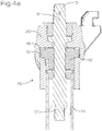
- FIGS. 4a and 4b show sectional views of an exemplary transmission in two different positions.
- the reference symbols correspond to the following components: Riser pipe 1, shut-off device 2, shut-off element 3, drain line 4, actuating element 5, axis of rotation 6, surface 7 in the form of a rotational body, jacket 8, through opening 9, continuous area (to close the liquid supply) 10, clearance 11, continuous area (to close the drain line) 12 , Feed line 13, feed opening 14, gear 15, shaft 16, spindle drive 17, gate 18, scanning element 19, sleeve 20, adjusting thread 21.
- Fig. 1 shows a sectional representation of an embodiment of a hydrant according to the invention, the representation being interrupted at two points so that relevant components can be represented without the full length of the hydrant having to be mapped.
- the hydrant comprises a riser pipe 1, which in the present embodiment is constructed in several parts.
- This riser pipe 1 extends essentially from an actuating element 5 to the supply line 13, which protrudes into the riser pipe 1 on one side like a nozzle and on its other side can be connected to a subterranean liquid line.
- the connection can take place in a conventional manner, for example via a pipe coupling and in particular via a flange connection.
- the hydrant also comprises a shut-off device 2.
- the shut-off device 2 comprises a shut-off element 3, which in the present embodiment is bell-shaped and has a jacket 8, the jacket being delimited at least on its inner jacket surface by a surface 7 in the form of a rotational body.
- the shut-off element 3 is connected to a shaft 16. This shaft 16 is used for coupling or torque transmission from the actuating element 5 to the shut-off element 3.
- the shaft 16 is constructed in several parts.
- the shaft 16 is telescopic and comprises two subregions that can be pushed into one another.
- the parts of the shaft 16 are coupled to one another in such a way that they have a degree of freedom with respect to one another along the longitudinal extent, in particular along the axis of rotation 6, and are displaced telescopically with respect to one another.
- This degree of freedom or this mobility can optionally be locked using a suitable means such as a clamping screw.
- a suitable means such as a clamping screw.
- the parts of the shaft 16 are not round but equipped with a polygonal plug-in connection, with which a rotary connection can be established.
- the hydrant of the Fig. 1 comprises an emptying line 4 which is designed for emptying the riser pipe 1.
- the hydrant preferably comprises a connection or outlet in the upper region of the riser pipe 1 through which the liquid flowing into the riser pipe 1 can be removed.
- the shut-off element 3 can be shifted into different rotational positions, as will be discussed in detail in the following figures.
- the displacement takes place by rotating the shut-off element 3 about the axis of rotation 6.
- the feed opening 14 of the feed line 13 can optionally be closed or opened by the shut-off element 3.
- this gear mechanism 15 comprises a spindle drive 17, a gate 18 and a scanning element 19 which is not visible in this illustration.
- Fig. 2 shows an oblique view of an embodiment of a hydrant according to the invention, in particular the embodiment from FIG Fig. 1 , in which, however, some components are partially hidden for better visibility.
- the hydrant in particular the shut-off device 2 is in the first rotational position. In this the liquid supply is blocked. In this rotational position, the shut-off element 3 is arranged opposite the feed line 13 in such a way that a continuous area 10 of the shut-off element 3, in particular a continuous area 10 of the jacket 8 of the shut-off element 3, closes the feed opening 14 of the feed line 13, which is not visible here.
- the through opening 9 of the shut-off element 3 in particular does not overlap with the supply opening 14 in this position.
- the shut-off element 3 has a surface 7 in the form of a rotational body, the axis of rotation of which coincides with the axis of rotation 6.
- the shaft 16 is polygonal, in particular square, in order to enable a torque transmission, although the shaft 16 is telescopic and is therefore adjustable in length along the axis of rotation 6.
- the hydrant of the Fig. 2 comprises an emptying line 4.
- This emptying line 4 is arranged in the lower region of the ascending pipe 1 in order to enable emptying, in particular complete emptying, of the ascending pipe 1.
- the drain line 4 can be opened and closed by actuating the shut-off device 2.
- the shut-off element 3 or the shut-off device 2 comprises an exposure 11 which, in the present position, is arranged in the area of the inlet of the drainage line 4. In this position the drain line 4 is open. In addition, however, the shut-off device 2 also comprises a continuous area 12 for closing the emptying line 4.
- the riser pipe 1 is constructed in several parts, whereby a length adjustment of the riser pipe 1 is made possible.
- the riser pipe 1 comprises an adjusting thread 21, which causes a change in length when one part of the riser pipe 1 is rotated relative to the other part of the riser pipe 1.
- Fig. 3 shows the embodiment of Fig. 2 but in the second rotary position.
- the liquid supply into the riser pipe 1 is open.
- liquid can flow from the subterranean liquid line (not shown) through the supply line 13 and its supply opening 14 and then through the through opening 9 of the shut-off element 3 of the shut-off device 2 into the riser pipe 1.
- the through opening 9 of the shut-off element 3 is located in the area of the feed opening 14 of the feed line 13.
- a liquid supply is given in particular when the supply opening 14 and the through opening 9 have an overlap and thus overlap one another.
- the shut-off device 2 is completely open and the passage opening 9 is located centrally above or in front of the feed opening 14, whereby a maximum cross section is released.
- the drain line 4 is closed in that the continuous area 12 of the shut-off device 2 closes the inlet of the drain line 4.
- the shut-off device 2 is actuated by rotating the shut-off element 3, with the between the rotational position of the Fig. 2 and the rotational position of the Fig. 3 further intermediate positions can occur in which the flow or the volume flow can be reduced compared to a full flow.
- the Figures 4a and 4b show sectional views to explain the function of a preferred gear 15.
- the gear 15 comprises a spindle drive 17 which is driven by actuating or rotating the actuating element 5.
- the scanning element 19 is moved along the axis of rotation 6 via the spindle drive 17.
- the link 18 is provided in a sleeve 20, the scanning element 19 being displaced along the axis of rotation 6 by actuating the spindle drive 17.
- the scanning element 19 is moved along the link 18 without the sleeve 20 or the link 18 being rotated or moved.
- the link 18 is designed as a helical groove in the interior of the sleeve 20.
- At least one scanning element 19 is provided, two scanning elements 19 being provided in the present embodiment, which protrude on both sides on diametrically opposite sides.
- the cutting plane is in the Figures 4a and 4b selected so that it runs through the scanning element 19 and through the scanning elements 19 in both representations. If the scanning element 19 is now displaced along the axis of rotation 6, the scanning elements 19 are moved or guided along the link 18. Since the link 18 is arranged helically or at an angle, the scanning elements 19 pivot or rotate.
- a hydrant according to the invention in particular a preferred embodiment of a hydrant according to the invention, is operated as follows: In a first step, the actuating element 5 is actuated. It may be necessary for this to remove a protective cap and, in particular, to use a suitable tool to rotate the actuating element 5. The rotation of the actuating element 5 actuates a spindle drive 17 which displaces at least one scanning element 19 along the axis of rotation 6.
- the scanning elements 19 are pivoted about the axis of rotation 6 by the movement along the link 18. By rotating the scanning elements 19 and connecting the scanning elements 19 to the shut-off element 3, the shut-off element 3 is also moved.
- the shut-off element 3 comprises a passage opening 9. This is rotated by turning the shut-off element 3 to a feed opening 14 of a feed line 13 so that the liquid can enter the riser 1 of the hydrant through the feed line 13.
- the liquid can then be withdrawn from the riser pipe 1 via a suitable opening. If the hydrant is to be shut off again, the actuating element 5 is rotated in the opposite direction. As a result, the shut-off device 2 is closed again in a manner analogous to that described above. At the same time or after the shut-off device 2 has been closed, an emptying line 4 is opened. In particular, this emptying line 4 is opened via a clearance 11 provided in the shut-off element 3. The liquid located in the riser pipe 1 after the shut-off can be discharged through the emptying line 4.
- the shut-off device 2 and the gear 15 as well as the shaft 16 are arranged within the riser pipe 1, whereby the riser pipe 1 also acts as a housing for the components of the hydrant.
- the axes of rotation 6 of the shut-off element 3, the spindle drive 17, the scanning element 19, the shut-off element 3 and the shaft 16 preferably run coaxially.
Abstract
Hydrant, umfassend: ein Steigrohr (1), eine Absperrvorrichtung (2) mit einem Absperrelement (3) zum wahlweisen Öffnen oder Schließen der Flüssigkeitszufuhr aus einer unterirdisch verlaufenden Flüssigkeitsleitung in das Steigrohr (1), eine Entleerungsleitung (4) zur Entleerung des Steigrohrs (1) bei geschlossener Absperrvorrichtung (2), und ein Betätigungselement (5) zur Betätigung der Absperrvorrichtung (2), wobei das Absperrelement (3) um eine Drehachse (6) drehbar gelagert ist, wobei das Absperrelement (3) wahlweise eine erste Drehstellung aufweist, in der die Flüssigkeitszufuhr aus der Flüssigkeitsleitung in das Steigrohr (1) durch das Absperrelement (3) geschlossen ist und die Entleerungsleitung (4) geöffnet ist, und wobei das Absperrelement (3) wahlweise eine zweite Drehstellung aufweist, in der die Flüssigkeitszufuhr aus der Flüssigkeitsleitung in das Steigrohr (1) durch das Absperrelement (3) geöffnet ist und die Entleerungsleitung (4) geschlossen ist. Das Betätigungselement (5) ist mit dem Absperrelement (3) über ein Getriebe (15) und insbesondere auch über eine Welle (16) drehbar gekoppelt und das Getriebe (15) weist eine Untersetzung auf, durch die bei einer Drehung des Betätigungselements (5) um einen Betätigungswinkel das Absperrelement (3) um einen Absperrwinkel gedreht wird, der kleiner ist als der Betätigungswinkel.Hydrant, comprising: a riser pipe (1), a shut-off device (2) with a shut-off element (3) for optionally opening or closing the liquid supply from an underground liquid line into the riser pipe (1), an emptying line (4) for emptying the riser pipe ( 1) with the shut-off device (2) closed, and an actuating element (5) for actuating the shut-off device (2), the shut-off element (3) being rotatably mounted about an axis of rotation (6), the shut-off element (3) optionally having a first rotary position , in which the liquid supply from the liquid line into the riser pipe (1) is closed by the shut-off element (3) and the drainage line (4) is open, and the shut-off element (3) optionally has a second rotary position in which the liquid feed from the The liquid line in the riser pipe (1) is opened by the shut-off element (3) and the drainage line (4) is closed. The actuating element (5) is rotatably coupled to the shut-off element (3) via a gear (15) and in particular also via a shaft (16), and the gear (15) has a reduction ratio which, when the actuating element (5) rotates, the shut-off element (3) is rotated by an actuation angle by a shut-off angle which is smaller than the actuation angle.
Description
Die Erfindung betrifft einen Hydranten gemäß dem Oberbegriff des unabhängigen Patentanspruchs.The invention relates to a hydrant according to the preamble of the independent claim.
Hydranten sind in unterschiedlichen Ausführungsformen seit langer Zeit bekannt und publiziert. Hydranten werden in der Regel dazu verwendet, einen Zugang zu einer im Boden verlegten Leitung für Flüssigkeiten, insbesondere einer Wasserleitung, herzustellen.Various forms of hydrants have been known and published for a long time. Hydrants are usually used to provide access to a pipe for liquids laid in the ground, in particular a water pipe.
Hierzu umfassen herkömmliche Hydranten jeweils ein Steigrohr, das sich von der unterirdisch verlaufenden Flüssigkeitsleitung bis an die Oberfläche und in der Regel auch bis zu einer gewissen Bedienhöhe erstreckt.For this purpose, conventional hydrants each include a riser pipe that extends from the underground liquid line to the surface and, as a rule, also to a certain operating height.
Zum Herstellen bzw. Absperren der Flüssigkeitszufuhr in das Steigrohr umfassen dem Stand der Technik entsprechende Hydranten eine über ein Betätigungselement bedienbare Absperrvorrichtung, wie beispielsweise ein Kolbenventil. Herkömmliche Absperrvorrichtungen werden in der Regel derart betätigt, dass ein Absperrelement gegen den Flüssigkeitsdruck bewegt und auf einen Ventilsitz aufgepresst wird. Das Überwinden der vom Flüssigkeitsdruck ausgehenden Kräfte erschwert die Bedienung. Zudem werden in der Praxis durch die hohen Bedienkräfte auch der Ventilsitz und das Dichtelement übermäßig beansprucht, wodurch sich die Lebensdauer dieser Elemente reduziert. Darüber hinaus ist es bei Hydranten notwendig, eine Abdichtung über lange Zeit zu gewährleisten, was bei unter Druck stehenden Ventilsitzen ebenfalls problematisch sein kann.To establish or shut off the liquid supply into the riser pipe, hydrants corresponding to the prior art comprise a shut-off device, such as a piston valve, which can be operated via an actuating element. Conventional shut-off devices are usually operated in such a way that a shut-off element is moved against the liquid pressure and pressed onto a valve seat. Overcoming the forces emanating from the fluid pressure makes operation more difficult. In addition, the valve seat and the The sealing element is excessively stressed, which reduces the service life of these elements. In addition, with hydrants it is necessary to ensure a seal over a long period of time, which can also be problematic when valve seats are under pressure.
Herkömmliche Hydranten verfügen auch über eine Entleerungsleitung, die eine Entleerung des Steigrohrs ermöglicht, wenn die Flüssigkeitszufuhr abgesperrt ist. Dies insbesondere, um zu verhindern, dass im Steigrohr verbleibende Flüssigkeit bzw. Eis zu einer Beschädigung des Hydranten führt. Als Flüssigkeiten im Sinne der Erfindung gelten insbesondere flüssige Stoffe wie Wasser, fließfähige Suspensionen, fließfähige Schäume oder dergleichen.Conventional hydrants also have a drain line that allows the riser pipe to be drained when the fluid supply is shut off. This in particular to prevent the liquid or ice remaining in the riser pipe from damaging the hydrant. Liquids in the context of the invention are in particular liquid substances such as water, flowable suspensions, flowable foams or the like.
Aufgabe der Erfindung ist es nun, einen Hydranten bereitzustellen, dessen Bedienbarkeit und Sicherheit gegenüber herkömmlichen Hydranten verbessert ist.The object of the invention is now to provide a hydrant, the operability and safety of which is improved compared to conventional hydrants.
Die erfindungsgemäße Aufgabe wird insbesondere durch die Merkmale des unabhängigen Patentanspruchs gelöst.The object according to the invention is achieved in particular by the features of the independent patent claim.
Die Erfindung betrifft insbesondere einen Hydranten, umfassend:
- ein Steigrohr,
- eine Absperrvorrichtung mit einem Absperrelement zum wahlweisen Öffnen oder Schließen der Flüssigkeitszufuhr aus einer unterirdisch verlaufenden Flüssigkeitsleitung in das Steigrohr,
- eine Entleerungsleitung zur Entleerung des Steigrohrs bei geschlossener Absperrvorrichtung,
- und ein Betätigungselement zur Betätigung der Absperrvorrichtung.
- a riser pipe,
- a shut-off device with a shut-off element for the optional opening or closing of the liquid supply from an underground liquid line into the riser pipe,
- an emptying line for emptying the riser pipe when the shut-off device is closed,
- and an actuating element for actuating the shut-off device.
Bevorzugt ist vorgesehen, dass das Absperrelement um eine Drehachse drehbar gelagert ist, dass das Absperrelement wahlweise eine erste Drehstellung aufweist, in der die Flüssigkeitszufuhr aus der Flüssigkeitsleitung in das Steigrohr durch das Absperrelement geschlossen ist und die Entleerungsleitung geöffnet ist, und dass das Absperrelement wahlweise eine zweite Drehstellung aufweist, in der die Flüssigkeitszufuhr aus der Flüssigkeitsleitung in das Steigrohr durch das Absperrelement geöffnet ist und die Entleerungsleitung geschlossen ist.It is preferably provided that the shut-off element is rotatably mounted about an axis of rotation, that the shut-off element optionally has a first rotary position in which the liquid supply from the liquid line into the riser is closed by the shut-off element and the drainage line is open, and that the shut-off element optionally has a has second rotational position in which the Liquid supply from the liquid line into the riser is opened through the shut-off element and the drainage line is closed.
Gegebenenfalls ist vorgesehen, dass die Entleerungsleitung in der zweiten Drehstellung durch das Absperrelement geschlossen ist, und insbesondere dass die Entleerungsleitung in der ersten Drehstellung durch das Absperrelement freigegeben ist.If necessary, it is provided that the emptying line is closed by the shut-off element in the second rotary position, and in particular that the emptying line is released by the shut-off element in the first rotary position.
Gegebenenfalls ist vorgesehen, dass das Absperrelement zumindest abschnittsweise einer rotationskörperförmigen Fläche folgt, deren Rotationsachse konzentrisch mit der Drehachse verläuft.If necessary, it is provided that the shut-off element follows, at least in sections, a surface in the form of a rotational body, the axis of rotation of which runs concentrically with the axis of rotation.
Gegebenenfalls ist vorgesehen, dass das Absperrelement zylinderförmig und/oder glockenförmig ausgebildet ist, dass das Absperrelement in seinem Mantel mindestens eine Durchgangsöffnung zum Öffnen der Flüssigkeitszufuhr und einen durchgehenden Bereich zum Schließen der Flüssigkeitszufuhr aufweist.If necessary, it is provided that the shut-off element is cylindrical and / or bell-shaped, that the shut-off element has at least one passage opening in its jacket for opening the liquid supply and a continuous area for closing the liquid supply.
Gegebenenfalls ist vorgesehen, dass das Absperrelement mindestens eine Freistellung zum Öffnen der Entleerungsleitung und einen durchgehenden Bereich zum Schließen der Entleerungsleitung aufweist, und insbesondere dass die Freistellung zum Öffnen der Entleerungsleitung und der durchgehenden Bereich zum Schließen der Entleerungsleitung in dem Mantel vorgesehen ist oder ein Teil des Mantels ist.If necessary, it is provided that the shut-off element has at least one clearance for opening the drainage line and a continuous area for closing the drainage line, and in particular that the clearance for opening the drainage line and the continuous area for closing the drainage line is provided in the jacket or part of the Coat is.
Gegebenenfalls ist vorgesehen, dass eine Zuführungsleitung zur Zuführung der Flüssigkeit in das Steigrohr vorgesehen ist, dass sich die Zuführungsleitung stutzenförmig in das Steigrohr erstreckt, dass die Zuführungsleitung, insbesondere ihre Mantelfläche, eine Zuführungsöffnung aufweist, und dass die Zuführungsöffnung in der ersten Drehstellung des Absperrelements durch das Absperrelement, insbesondere durch den durchgehenden Bereich zum Schließen der Flüssigkeitszufuhr, verschlossen ist.If necessary, provision is made for a feed line to be provided for feeding the liquid into the riser pipe, for the feed line to extend into the riser pipe in the shape of a connector, for the feed line, in particular its lateral surface, to have a feed opening, and for the feed opening to pass through in the first rotational position of the shut-off element the shut-off element is closed, in particular by the continuous area for closing the liquid supply.
Gegebenenfalls ist vorgesehen, dass eine Zuführungsleitung zur Zuführung der Flüssigkeit in das Steigrohr vorgesehen ist.If necessary, it is provided that a feed line is provided for feeding the liquid into the riser pipe.
Gegebenenfalls ist vorgesehen, dass sich die Zuführungsleitung stutzenförmig in das Steigrohr erstreckt.If necessary, it is provided that the supply line extends into the riser pipe in the shape of a connector.
Gegebenenfalls ist vorgesehen, dass die Zuführungsleitung, insbesondere in ihrer Mantelfläche, eine Zuführungsöffnung aufweist.If necessary, it is provided that the feed line, in particular in its jacket surface, has a feed opening.
Gegebenenfalls ist vorgesehen, dass die Durchgangsöffnung des Absperrelements und die Zuführungsöffnung in der zweiten Drehstellung des Absperrelements derart zueinander positioniert sind, dass die Flüssigkeitszufuhr in das Steigrohr geöffnet ist.If necessary, it is provided that the through-opening of the shut-off element and the feed opening are positioned relative to one another in the second rotational position of the shut-off element in such a way that the liquid feed into the riser pipe is opened.
Bevorzugt ist vorgesehen, dass das Betätigungselement mit dem Absperrelement über ein Getriebe und insbesondere auch über eine Welle drehbar gekoppelt ist.It is preferably provided that the actuating element is rotatably coupled to the shut-off element via a gear and in particular also via a shaft.
Bevorzugt ist vorgesehen, dass das Getriebe eine Untersetzung aufweist, durch die bei einer Drehung des Betätigungselements um einen Betätigungswinkel das Absperrelement um einen Absperrwinkel gedreht wird, der kleiner ist als der Betätigungswinkel.It is preferably provided that the transmission has a reduction ratio by which, when the actuating element is rotated through an actuating angle, the shut-off element is rotated through a shut-off angle which is smaller than the actuation angle.
Gegebenenfalls ist vorgesehen, dass die Untersetzung zwischen 1:10 bis 1:50, vorzugsweise 1:40 beträgt.If necessary, it is provided that the reduction is between 1:10 and 1:50, preferably 1:40.
Gegebenenfalls ist vorgesehen, dass das Getriebe mindestens eine Kulisse umfasst.If necessary, it is provided that the transmission includes at least one gate.
Gegebenenfalls ist vorgesehen, dass das Getriebe ein mit der Kulisse in Wirkkontakt stehendes Abtastelement umfasst.If necessary, it is provided that the transmission comprises a scanning element which is in operative contact with the link.
Gegebenenfalls ist vorgesehen, dass das Getriebe einen Spindelantrieb zur Bewegung des Abtastelements entlang der Drehachse umfasst.If necessary, it is provided that the transmission includes a spindle drive for moving the scanning element along the axis of rotation.
Gegebenenfalls ist vorgesehen, dass die Kulisse schräg und/oder schraubenförmig zur Drehachse verläuft.If necessary, it is provided that the link runs obliquely and / or helically to the axis of rotation.
Gegebenenfalls ist vorgesehen, dass das Abtastelement derart gelagert ist, dass es bei einer Bewegung entlang der Drehachse und entlang der Kulisse um die Drehachse (6) verschwenkt wird.If necessary, it is provided that the scanning element is mounted in such a way that it is pivoted about the axis of rotation (6) when it moves along the axis of rotation and along the link.
Gegebenenfalls ist vorgesehen, dass das Abtastelement zur Betätigung der Absperrvorrichtung mit dem Absperrelement drehverbunden bzw. drehgekoppelt ist.If necessary, it is provided that the scanning element for actuating the shut-off device is rotatably connected or rotatably coupled to the shut-off element.
Gegebenenfalls ist vorgesehen, dass die Kulisse als in einer Hülse angeordnete schräg oder schraubenförmig verlaufende Nut ausgebildet ist, und dass insbesondere mehrere derartiger Nuten in der Hülse vorgesehen sind, die bei einer Bewegung des Abtastelements entlang der Drehachse die Abtastelemente um die Drehachse verdrehen.If necessary, it is provided that the link is designed as an inclined or helical groove arranged in a sleeve, and that in particular several such grooves are provided in the sleeve, which rotate the scanning elements about the axis of rotation when the scanning element moves along the axis of rotation.
Gegebenenfalls ist vorgesehen, dass die Welle eine veränderbare Länge aufweist und insbesondere teleskopisch ausgebildet ist.If necessary, it is provided that the shaft has a variable length and, in particular, is designed to be telescopic.
Gegebenenfalls ist vorgesehen, dass das Steigrohr eine veränderbare Länge aufweist und insbesondere teleskopisch ausgebildet ist.If necessary, it is provided that the riser pipe has a variable length and, in particular, is designed to be telescopic.
Durch die erfindungsgemäße Konstruktion wird eine Absperrvorrichtung geschaffen, deren Absperrelement nicht gegen den Flüssigkeitsdruck bewegt werden muss, um eine Absperrung des Hydranten herbeizuführen. So ist das Absperrelement bevorzugt ein drehbar gelagertes Absperrelement, das zumindest abschnittsweise einer rotationskörperförmigen Fläche folgt, wobei die Rotationsachse der Fläche konzentrisch mit der Drehachse der Bewegung des Absperrelements verläuft. Im Gegensatz zu herkömmlichen Ventilen wird durch diese Form der Absperrvorrichtung zur Absperrung eine Bewegung des Absperrelements im Wesentlichen normal zur Strömungsrichtung der austretenden Flüssigkeit ausgeführt. Dadurch können die zum Absperren benötigten Kräfte reduziert werden.The construction according to the invention creates a shut-off device, the shut-off element of which does not have to be moved against the pressure of the liquid in order to shut off the hydrant. Thus, the shut-off element is preferably a rotatably mounted shut-off element which at least in sections follows a surface in the form of a rotational body, the axis of rotation of the surface running concentrically with the axis of rotation of the movement of the shut-off element. In contrast to conventional valves, this form of the shut-off device means that the shut-off element moves essentially normal to the direction of flow of the exiting liquid. In this way, the forces required to shut off can be reduced.
Überdies wirkt auch im abgesperrten Zustand der Flüssigkeitsdruck bevorzugt normal zur Bewegungsrichtung des Absperrelements, insbesondere zum einzigen Freiheitsgrad des Absperrelements, womit diese Kräfte nicht in oder gegen die Bewegungsrichtung des Absperrelements sondern im Wesentlichen normal zu dieser verlaufen. Dadurch ist einerseits die Bedienbarkeit beim Öffnen und Schließen, andererseits aber auch die Zuverlässigkeit der Absperrung verbessert.In addition, even in the shut-off state, the liquid pressure preferably acts normal to the direction of movement of the shut-off element, in particular to the only degree of freedom of the shut-off element, so that these forces are not in or against the Direction of movement of the shut-off element but essentially normal to this. This improves the operability when opening and closing on the one hand, but also improves the reliability of the shut-off on the other hand.
Das Absperrelement der Absperrvorrichtung weist zumindest zwei Drehstellungen auf, in die es wahlweise bewegt werden kann. In einer ersten Drehstellung ist die Flüssigkeitszufuhr aus der Flüssigkeitsleitung in das Steigrohr durch das Absperrelement geschlossen. In der zweiten Drehstellung ist die Flüssigkeitszufuhr aus der Flüssigkeitsleitung in das Steigrohr geöffnet. Zudem gibt es gegebenenfalls auch mindestens eine Zwischenstellung zwischen der ersten und der zweiten Drehstellung, in der eine Öffnung nur teilweise erfolgt, womit beispielsweise der Durchfluss bzw. der Volumenstrom reguliert werden kann.The shut-off element of the shut-off device has at least two rotary positions into which it can be moved as required. In a first rotary position, the liquid supply from the liquid line into the riser pipe is closed by the shut-off element. In the second rotary position, the liquid supply from the liquid line into the riser pipe is open. In addition, there is optionally also at least one intermediate position between the first and the second rotary position, in which an opening only takes place partially, with which, for example, the flow rate or the volume flow can be regulated.
Insbesondere umfasst der Hydrant eine Zuführungsleitung, die beispielsweise einen rohrförmigen, runden Querschnitt aufweist und stutzenförmig in das Steigrohr ragt. Die Zuführungsleitung umfasst eine Zuführungsöffnung, die beispielsweise den Mantel der Zuführungsleitung durchsetzt. Die Zuführungsleitung ist in dieser Ausführungsform bevorzugt rohrförmig mit einem runden Rohrquerschnitt ausgebildet, wobei die Zuführungsöffnung als durch den Mantel des Rohrs verlaufende Durchgangsöffnung ausgebildet ist.In particular, the hydrant comprises a supply line which, for example, has a tubular, round cross section and protrudes into the riser pipe in the shape of a nozzle. The feed line comprises a feed opening which, for example, penetrates the jacket of the feed line. In this embodiment, the supply line is preferably tubular with a round tube cross-section, the supply opening being designed as a through opening running through the jacket of the tube.
Das Absperrelement kann beispielsweise rotationskörperförmig, hohlzylinderförmig, rohrförmig, ringförmig oder glockenförmig ausgebildet sein und die Zuführungsleitung von außen umgreifen oder auch innerhalb der Zuführungsleitung angeordnet sein. Dadurch, dass das Absperrelement in seinem Mantel eine Durchgangsöffnung und einen durchgehenden Bereich aufweist, kann durch Verdrehen des Absperrelements ein Öffnen bzw. ein Schließen der Flüssigkeitszufuhr bewirkt werden.The shut-off element can, for example, be in the form of a body of revolution, hollow cylindrical, tubular, ring-shaped or bell-shaped and encompass the supply line from the outside or also be arranged inside the supply line. Because the shut-off element has a through opening and a continuous area in its jacket, the liquid supply can be opened or closed by rotating the shut-off element.
Wird der durchgehende Bereich des Absperrelements vor die Zuführungsöffnung der Zuführungsleitung gedreht, so ist die Zuführungsöffnung durch den durchgehenden Bereich des Absperrelements verschlossen. Wird das Absperrelement aus dieser ersten Drehstellung verdreht, so kommt es in einer Zwischenstellung zuerst zu einer Überschneidung der Durchgangsöffnung und der Zuführungsöffnung, womit ein gewisser Volumenstrom an Flüssigkeit in das Steigrohr eintreten kann. Wird das Absperrelement weiter bewegt, so wird die Überschneidung der Durchgangsöffnung und der Zuführungsöffnung immer größer, womit auch der eintretende Volumenstrom erhöht wird.If the continuous area of the shut-off element is rotated in front of the feed opening of the feed line, the feed opening is closed by the continuous area of the shut-off element. If the shut-off element is rotated from this first rotational position, then in an intermediate position the passage opening and the supply opening first overlap, which in turn leads to an overlap a certain volume flow of liquid can enter the riser pipe. If the shut-off element is moved further, the intersection of the passage opening and the supply opening becomes larger and larger, which also increases the volume flow entering.
In der komplett geöffneten Stellung liegt die Durchgangsöffnung des Absperrelements bevorzugt über der oder konzentrisch zur Zuführungsöffnung der Zuführungsleitung.In the completely open position, the through opening of the shut-off element is preferably above or concentric to the feed opening of the feed line.
Zudem kann erfindungsgemäß vorgesehen sein, dass auch die Entleerungsleitung durch die Betätigung des Absperrelements betätigt wird. So weist das Absperrelement bevorzugt eine Freistellung zum Öffnen der Entleerungsleitung und einen durchgehenden Bereich zum Schließen der Entleerungsleitung auf.In addition, it can be provided according to the invention that the drain line is also actuated by actuating the shut-off element. Thus, the shut-off element preferably has an opening for opening the drainage line and a continuous area for closing the drainage line.
Die Entleerungsleitung ist bevorzugt im unteren Bereich des Steigrohrs angeordnet, um eine Entleerung, insbesondere eine vollständige Entleerung, des Steigrohrs zu ermöglichen.The emptying line is preferably arranged in the lower region of the ascending pipe in order to enable emptying, in particular complete emptying, of the ascending pipe.
Bevorzugt sind diese Elemente derart am Absperrelement angeordnet, dass die Entleerungsleitung geschlossen ist, wenn die Flüssigkeitszufuhr in das Steigrohr geöffnet ist, und dass die Entleerungsleitung geöffnet ist, wenn die Flüssigkeitszufuhr in das Steigrohr verschlossen ist. Dadurch kann eine selbsttätige Entleerung des Steigrohrs bewirkt werden, wenn die Flüssigkeitszufuhr gestoppt ist.These elements are preferably arranged on the shut-off element in such a way that the emptying line is closed when the liquid supply into the riser pipe is open, and that the emptying line is open when the liquid supply into the riser pipe is closed. As a result, the riser pipe can be automatically emptied when the supply of liquid is stopped.
Das Betätigungselement ist mit dem Absperrelement bevorzugt über ein Getriebe gekoppelt. Dies bedeutet, dass entlang des vom Betätigungselement zum Absperrelement wirkenden Kraft- bzw. Drehmomentverlaufs ein Getriebe angeordnet ist. Entlang dieses Antriebsstrangs zur Betätigung des Absperrelements können neben einem Getriebe auch noch eine oder mehrere Wellen oder andere Elemente, wie beispielsweise Kupplungen, teleskopische Verbindungen und/oder Steckverbindungen vorgesehen sein.The actuating element is preferably coupled to the shut-off element via a transmission. This means that a transmission is arranged along the force or torque curve acting from the actuating element to the shut-off element. Along this drive train for actuating the shut-off element, one or more shafts or other elements, such as, for example, couplings, telescopic connections and / or plug connections, can also be provided in addition to a transmission.
Das Getriebe weist bevorzugt eine Untersetzung auf. Dies bedeutet, dass bei einer Drehung des Betätigungselements um einen gewissen Betätigungswinkel das Absperrelement um einen Absperrwinkel gedreht wird, wobei der Absperrwinkel jedoch kleiner ist als der Betätigungswinkel. Eine beispielhafte Untersetzung beträgt 1:40. Dies bedeutet, dass bei zehn Umdrehungen des Betätigungselements das Absperrelement um eine Viertelumdrehung, also um 90°, verdreht wird.The transmission preferably has a reduction. This means that when the operating element is rotated through a certain operating angle, the Shut-off element is rotated by a shut-off angle, the shut-off angle, however, being smaller than the actuation angle. An exemplary reduction is 1:40. This means that when the actuating element is rotated ten times, the shut-off element is rotated by a quarter of a turn, that is to say by 90 °.
Bevorzugt ist zur Verlagerung des Absperrelements von der ersten Drehstellung in die zweite Drehstellung eine Verschwenkung des Absperrelements um 90° vonnöten. Gemäß weiterer Ausführungsformen kann Verschwenkung von der ersten Drehstellung in die zweite Drehstellung etwa 45°, etwa 90° oder etwa 180° betragen.In order to move the shut-off element from the first rotational position into the second rotational position, it is preferable for the shut-off element to pivot through 90 °. According to further embodiments, pivoting from the first rotational position into the second rotational position can be approximately 45 °, approximately 90 ° or approximately 180 °.
Grundsätzlich kann hierfür jedes Getriebe eingesetzt werden, das den technischen Anforderungen bezüglich Untersetzung, Standzeit, Drehmoment etc. entspricht. Ein beispielhaftes Getriebe umfasst einen Spindelantrieb, eine Kulisse und ein Abtastelement.In principle, any gear can be used that meets the technical requirements in terms of reduction, service life, torque, etc. An exemplary transmission includes a spindle drive, a gate and a sensing element.
Durch das Betätigungselement kann eine Spindel angetrieben werden, durch die eine Kulisse entlang der Drehachse linear und insbesondere translatorisch verschoben wird. Die Kulisse ist beispielsweise eine schräg- oder schraubförmig verlaufende Nut oder ein schräg- oder schraubförmig verlaufender Steg, die /der beispielsweise in der Innenseite einer Hülse vorgesehen ist. Bei der Bewegung entlang der Drehachse wird die Kulisse bevorzugt gerade geführt und daher nicht verdreht. Ferner umfasst dieses Getriebe mindestens ein Abtastelement, das derart mit der Kulisse in Wirkkontakt steht, dass es bei dem Verschieben der Kulisse um die oder um eine Drehachse verschwenkt wird. Die Verschwenkung des Abtastelements erfolgt im Vergleich zur Betätigung des Betätigungselements jedoch in stark eingeschränktem Umfang, was auf die Untersetzung zurückzuführen ist. Das Abtastelement ist in weiterer Folge mit dem Absperrelement gekoppelt, womit bei einer Verdrehung/Verschwenkung des Abtastelements auch das Absperrelement verdreht/verschwenkt wird.A spindle can be driven by the actuating element, by means of which a link is displaced linearly and in particular translationally along the axis of rotation. The backdrop is, for example, an obliquely or helically extending groove or an obliquely or helically extending web which is provided, for example, in the inside of a sleeve. When moving along the axis of rotation, the link is preferably guided straight and therefore not rotated. Furthermore, this transmission comprises at least one scanning element which is in operative contact with the link in such a way that it is pivoted about or about an axis of rotation when the link is displaced. The pivoting of the scanning element takes place to a very limited extent in comparison to the actuation of the actuating element, which is due to the reduction. The sensing element is then coupled to the shut-off element, so that when the sensing element is rotated / pivoted, the shut-off element is also rotated / pivoted.
Alternativ kann bei einer Verdrehung des Betätigungselements über den Spindelantrieb das Abtastelement entlang der Drehachse bewegt werden. Die Kulisse und/oder die Hülse bleiben dabei bevorzugt starr bzw. unbewegt. Wird das Abtastelement entlang der Drehachse verschoben, so werden die Abtastelemente entlang der Kulisse bewegt und/oder geführt. Da die Kulisse schraubförmig bzw. schräg angeordnet ist, kommt es hierbei zu einer Verschwenkung bzw. Verdrehung des Abtastelements bzw. der Abtastelemente. Diese Verschwenkung wird in weiterer Folge auf das Absperrelement übertragen, wobei die Übertragung bevorzugt über eine Welle geschieht. Zum Ausgleich der Verschiebung der Kulisse entlang der Drehachse ist die Welle oder zumindest eine Welle des Hydranten längenverstellbar und insbesondere teleskopisch ausgebildet. Bevorzugt ist die Welle zwischen dem Abtastelement und dem Absperrelement vorgesehen und koppelt das Absperrelement bevorzugt starr mit dem Abtastelement.Alternatively, when the actuating element is rotated, the scanning element can be moved along the axis of rotation via the spindle drive. The link and / or the sleeve preferably remain rigid or immobile. If the scanning element is displaced along the axis of rotation, the scanning elements are moved along the backdrop and / or guided. Since the link is arranged helically or at an angle, this results in a pivoting or rotation of the scanning element or the scanning elements. This pivoting is then transmitted to the shut-off element, the transmission preferably taking place via a shaft. To compensate for the displacement of the link along the axis of rotation, the shaft or at least one shaft of the hydrant is adjustable in length and, in particular, designed to be telescopic. The shaft is preferably provided between the scanning element and the shut-off element and preferably rigidly couples the shut-off element to the scanning element.
Zudem kann durch diese Konstruktion auch das Steigrohr längenverstellbar ausgebildet sein, wobei sich bei einer Längenverstellung des Steigrohrs die Länge der Welle automatisch bzw. selbsttätig mitändert. Beispielsweise kann das Steigrohr hierzu mehrteilig ausgebildet sein, wobei der eine Teil gegenüber dem anderen Teil entlang der Drehachse verlagerbar angeordnet ist. Die Verschiebung kann beispielsweise über eine Schraubverbindung ermöglicht sein. Die Längenverstellung erfolgt bevorzugt entlang der DrehachseIn addition, this construction can also make the riser pipe adjustable in length, with the length of the shaft changing automatically or automatically when the riser pipe is adjusted in length. For example, the riser pipe can be designed in several parts for this purpose, one part being arranged so as to be displaceable relative to the other part along the axis of rotation. The shift can be made possible, for example, via a screw connection. The length adjustment is preferably carried out along the axis of rotation
Durch die erfindungsgemäße Konstruktion muss zum Absperren der Flüssigkeitszufuhr die Flüssigkeitssäule nicht komprimiert oder verschoben werden. Vielmehr geschieht bei der erfindungsgemäßen Konstruktion die Absperrung ohne Volumensänderung und vereinfacht ausgedrückt durch Abschneiden des Flüssigkeitsstroms.Due to the construction according to the invention, the liquid column does not have to be compressed or displaced in order to shut off the liquid supply. Rather, in the construction according to the invention, the shut-off takes place without a change in volume and, to put it simply, by cutting off the flow of liquid.
Durch die Verwendung eines Getriebes mit einer Untersetzung wird die nachteilige Wirkung von herkömmlichen Kugelhähnen unterbunden, bei denen durch zu schnelles Schließen oder Öffnen Druckschläge hervorgerufen werden, die bei einer langsamen Betätigung, wie sie durch das Getriebe hervorgerufen wird, nicht oder nur in stark vermindertem Ausmaß auftreten. Durch die Untersetzung kann die Schließgeschwindigkeit bei manueller Betätigung so weit herabgesetzt werden, dass sich Drucksteigerungen in vertretbaren Grenzen halten.By using a gear with a reduction, the disadvantageous effect of conventional ball valves, in which closing or opening too quickly, pressure shocks are caused which, when actuated slowly, such as that caused by the gear, either not at all or only to a greatly reduced extent appear. With the reduction, the closing speed can be reduced so far with manual actuation that pressure increases are kept within acceptable limits.
Durch die Längenverstellbarkeit des Steigrohrs ist es möglich, eine flexible Anpassung des Hydranten einerseits an die Lage der unterirdischen Flüssigkeitsleitung als auch an das Erdniveau durchzuführen. Hierbei sind zwei Abschnitte des Steigrohrs teleskopisch miteinander über ein Gewinde verbunden. Durch Drehen des Hydranten kann die Höhe noch am Einsatzort stufenlos angepasst werden. Feststehend bleibt bevorzugt das Außenrohr, was auch eine nachträgliche Höhenanpassung ermöglicht, ohne dass der Hydrant bis zum Boden freigegraben werden muss. Die Länge der innenliegenden Welle passt sich automatisch an die Längenveränderung an, ohne dass das System zerlegt oder ausgegraben werden muss.As the riser pipe can be adjusted in length, it is possible to flexibly adapt the hydrant to the position of the underground liquid line on the one hand and to to carry out the earth level. Here, two sections of the riser pipe are telescopically connected to one another via a thread. By turning the hydrant, the height can be continuously adjusted at the place of use. The outer pipe preferably remains fixed, which also enables a subsequent height adjustment without the hydrant having to be dug to the ground. The length of the internal shaft automatically adapts to the change in length without the system having to be dismantled or excavated.
Durch die Segmentbauweise der zahnstangenartigen Gewindesegmente werden die Reibkräfte und auch die notwendigen Fertigungsgenauigkeiten reduziert, sodass das System auch noch nach längeren Standzeiten leicht mit Handwerkzeugen arretiert bzw. betätigt werden kann.The segment design of the rack-like thread segments reduces the frictional forces and also the necessary manufacturing accuracy, so that the system can easily be locked or actuated with hand tools even after long periods of inactivity.
Bevorzugt sind über den Umfang vier vertikal verlaufende zahnstangenartige Gewindesegmente verteilt. Diese greifen in Gewinde des jeweils anderen Teils ein.Preferably, four vertically running rack-like thread segments are distributed over the circumference. These engage in the thread of the other part.
Bevorzugt ermöglicht die erfindungsgemäße Ausgestaltung eine schmiermittelfreie Mechanik zur Betätigung des Hydranten.The configuration according to the invention preferably enables a lubricant-free mechanism for actuating the hydrant.
Weitere Details der Konstruktion können den Figuren und den Patentansprüchen entnommen werden.
-
Fig. 1 zeigt eine Schnittdarstellung einer Ausführungsform eines erfindungsgemäßen Hydranten. -
Fig. 2 zeigt eine Schrägansicht mit teilweise ausgeblendeten Komponenten, bei der sich das Absperrelement in der ersten Drehstellung befindet. -
Fig. 3 zeigt eine Schrägansicht mit teilweise ausgeblendeten Komponenten, bei der sich das Absperrelement in seiner zweiten Drehstellung befindet.
-
Fig. 1 shows a sectional view of an embodiment of a hydrant according to the invention. -
Fig. 2 shows an oblique view with partially hidden components, in which the shut-off element is in the first rotational position. -
Fig. 3 shows an oblique view with partially hidden components, in which the shut-off element is in its second rotational position.
Die
Wenn nicht anders angegeben, so entsprechen die Bezugszeichen folgenden Komponenten:
Steigrohr 1, Absperrvorrichtung 2, Absperrelement 3, Entleerungsleitung 4, Betätigungselement 5, Drehachse 6, rotationskörperförmige Fläche 7, Mantel 8, Durchgangsöffnung 9, durchgehender Bereich (zum Schließen der Flüssigkeitszufuhr) 10, Freistellung 11, durchgehender Bereich (zum Schließen der Entleerungsleitung) 12, Zuführungsleitung 13, Zuführungsöffnung 14, Getriebe 15, Welle 16, Spindelantrieb 17, Kulisse 18, Abtastelement 19, Hülse 20, Verstellgewinde 21.Unless otherwise stated, the reference symbols correspond to the following components:
Der Hydrant umfasst ein Steigrohr 1, das in der vorliegenden Ausführungsform mehrteilig ausgebildet ist. Dieses Steigrohr 1 erstreckt sich im Wesentlichen von einem Betätigungselement 5 bis zur Zuführungsleitung 13, die einseitig stutzenförmig in das Steigrohr 1 ragt und an ihrer anderen Seite mit einer unterirdisch verlaufenden Flüssigkeitsleitung verbunden werden kann. Die Verbindung kann in herkömmlicher Weise, beispielsweise über eine Rohrkupplung und insbesondere über eine Flanschverbindung, erfolgen.The hydrant comprises a
Der Hydrant umfasst zudem eine Absperrvorrichtung 2. Die Absperrvorrichtung 2 umfasst ein Absperrelement 3, das in der vorliegenden Ausführungsform glockenförmig ausgebildet ist und einen Mantel 8 aufweist, wobei der Mantel zumindest an seiner inneren Mantelfläche von einer rotationskörperförmigen Fläche 7 begrenzt ist. Im zusammenlaufenden Bereich der Glockenform ist das Absperrelement 3 mit einer Welle 16 verbunden. Diese Welle 16 dient der Koppelung bzw. der Drehmomentübertragung von dem Betätigungselement 5 auf das Absperrelement 3.The hydrant also comprises a shut-off
In der vorliegenden Ausführungsform ist die Welle 16 mehrteilig ausgebildet. Insbesondere ist die Welle 16 teleskopisch ausgebildet und umfasst zwei ineinander schiebbare Teilbereiche. Dabei sind die Teile der Welle 16 derart miteinander gekoppelt, dass sie entlang der Längserstreckung, insbesondere entlang der Drehachse 6 einen Freiheitsgrad gegenüber einander aufweisen und teleskopisch gegenüber einander verschoben werden. Dieser Freiheitsgrad bzw. diese Bewegbarkeit kann gegebenenfalls über ein geeignetes Mittel wie beispielsweise über eine Klemmschraube arretiert werden. Bei einer Drehung des einen Teils der Welle 16 gegenüber dem anderen Teil ist eine formschlüssige oder kraftschlüssige Kopplung gegeben, sodass die Welle 16 ihrer Funktion entsprechend ein Drehmoment übertragen kann. Beispielsweise sind die Teile der Welle 16 nicht rund sondern mit einer polygonförmige Steckverbindung ausgestattet, womit eine Drehverbindung hergestellt werden kann.In the present embodiment, the
Der Hydrant der
Zur Betätigung der Absperrvorrichtung 2 kann das Absperrelement 3 in unterschiedliche Drehstellungen verlagert werden, wie in den nachfolgenden Figuren im Detail erörtert wird. Die Verlagerung erfolgt durch Drehung des Absperrelements 3 um die Drehachse 6. Hierbei kann die Zuführungsöffnung 14 der Zuführungsleitung 13 wahlweise durch das Absperrelement 3 verschlossen oder geöffnet werden.To operate the shut-off
Zur Betätigung des Absperrelements 3 ist entlang des Kraftverlaufs zwischen dem Betätigungselement 5 und dem Absperrelement 3 ein Getriebe 15 vorgesehen. Dieses Getriebe 15 umfasst in der vorliegenden Ausführungsform einen Spindelantrieb 17, eine Kulisse 18 und ein in dieser Darstellung nicht sichtbares Abtastelement 19.To actuate the shut-off
Der Hydrant, insbesondere die Absperrvorrichtung 2, befindet sich in der ersten Drehstellung. In dieser ist die Flüssigkeitszufuhr abgesperrt. In dieser Drehstellung ist das Absperrelement 3 derart gegenüber der Zuführungsleitung 13 angeordnet, dass ein durchgehender Bereich 10 des Absperrelements 3, insbesondere ein durchgehender Bereich 10 des Mantels 8 des Absperrelements 3, die hier nicht sichtbare Zuführungsöffnung 14 der Zuführungsleitung 13 verschließt.The hydrant, in particular the shut-off
Die Durchgangsöffnung 9 des Absperrelements 3 weist in dieser Stellung insbesondere keine Überschneidung mit der Zuführungsöffnung 14 auf. Das Absperrelement 3 weist eine rotationskörperförmige Fläche 7 auf, deren Rotationsachse mit der Drehachse 6 übereinstimmt. Dadurch kann durch Verdrehen bzw. Verschwenken des Absperrelements 3 eine geführte und insbesondere dichtende Relativbewegung zwischen dem Absperrelement 3 und der Zuführungsleitung 13 erfolgen. Das Absperrelement 3 und die Zuführungsleitung 13 sowie auch weitere Komponenten können Dichtungen umfassen, um die Dichtwirkung zu verbessern.The through
Die Welle 16 ist in der vorliegenden Ausführungsform polygonförmig, insbesondere vierkantförmig ausgebildet, um eine Drehmomentübertragung zu ermöglichen, obwohl die Welle 16 teleskopisch und dadurch entlang der Drehachse 6 längenverstellbar ist.In the present embodiment, the
Der Hydrant der
In der vorliegenden Stellung ist die Entleerungsleitung 4 geöffnet, sodass im Steigrohr 1 befindliche Flüssigkeit selbsttätig durch die Entleerungsleitung 4 austreten kann. Hierzu umfasst das Absperrelement 3 bzw. die Absperrvorrichtung 2 eine Freistellung 11, die in der vorliegenden Stellung im Bereich des Eintritts der Entleerungsleitung 4 angeordnet ist. In dieser Stellung ist die Entleerungsleitung 4 geöffnet. Zusätzlich umfasst die Absperrvorrichtung 2 jedoch auch einen durchgehenden Bereich 12 zum Schließen der Entleerungsleitung 4.In the present position, the emptying
Das Steigrohr 1 ist mehrteilig ausgebildet, wodurch eine Längenverstellung des Steigrohrs 1 ermöglicht wird. Hierzu umfasst das Steigrohr 1 ein Verstellgewinde 21, das bei Verdrehen des einen Teils des Steigrohrs 1 gegenüber dem anderen Teil des Steigrohrs 1 eine Längenveränderung bewirkt.The
Eine Flüssigkeitszufuhr ist insbesondere dann gegeben, wenn die Zuführungsöffnung 14 und die Durchgangsöffnung 9 eine Überschneidung aufweisen und damit einander überlappen. In der vorliegenden Drehstellung ist die Absperrvorrichtung 2 komplett geöffnet und die Durchgangsöffnung 9 befindet sich mittig über oder vor der Zuführungsöffnung 14, womit ein maximaler Querschnitt freigegeben ist.A liquid supply is given in particular when the
In dieser Drehstellung ist die Entleerungsleitung 4 dadurch verschlossen, dass der durchgehende Bereich 12 der Absperrvorrichtung 2 den Eintritt der Entleerungsleitung 4 verschließt.In this rotational position, the
Grundsätzlich erfolgt die Betätigung der Absperrvorrichtung 2 durch Verdrehung des Absperrelements 3, wobei zwischen der Drehstellung der
Die
Bei einer Verdrehung des Betätigungselements 5 wird über den Spindelantrieb 17 das Abtastelement 19 entlang der Drehachse 6 bewegt. Die Kulisse 18 ist in der vorliegenden Ausführungsform in einer Hülse 20 vorgesehen, wobei durch Betätigung des Spindelantriebs 17 das Abtastelement 19 entlang der Drehachse 6 verschoben wird. Dabei wird das Abtastelement 19 entlang der Kulisse 18 bewegt, ohne dass die Hülse 20 oder die Kulisse 18 verdreht oder bewegt werden. Die Kulisse 18 ist in der vorliegenden Ausführungsform als schraubenförmige Nut im Inneren der Hülse 20 ausgebildet.When the
Zur Abtastung der Kulisse 18 ist zumindest ein Abtastelement 19 vorgesehen, wobei in der vorliegenden Ausführungsform zwei Abtastelemente 19 vorgesehen sind, die beidseitig an diametral gegenüberliegenden Seiten auskragen.For scanning the
Die Schnittebene ist in den
In der Praxis geschieht die Betätigung eines erfindungsgemäßen Hydranten, insbesondere einer bevorzugten Ausführungsform eines erfindungsgemäßen Hydranten, wie folgt:
In einem ersten Schritt wird das Betätigungselement 5 betätigt. Gegebenenfalls ist es hierfür notwendig, eine Schutzkappe abzunehmen und insbesondere ein passendes Werkzeug zur Verdrehung des Betätigungselements 5 zu benutzen. Die Drehung des Betätigungselements 5 betätigt einen Spindelantrieb 17, der mindestens ein Abtastelement 19 entlang der Drehachse 6 verschiebt.In practice, a hydrant according to the invention, in particular a preferred embodiment of a hydrant according to the invention, is operated as follows:
In a first step, the
Die Abtastelemente 19 werden durch die Bewegung entlang der Kulisse 18 um die Drehachse 6 verschwenkt. Durch die Verdrehung der Abtastelemente 19 und die Verbindung der Abtastelemente 19 mit dem Absperrelement 3 wird auch das Absperrelement 3 bewegt. Das Absperrelement 3 umfasst eine Durchgangsöffnung 9. Diese wird durch Verdrehung des Absperrelements 3 derart zu einer Zuführungsöffnung 14 einer Zuführungsleitung 13 verdreht, dass die Flüssigkeit durch die Zuführungsleitung 13 in das Steigrohr 1 des Hydranten eintreten kann.The
In weiterer Folge kann die Flüssigkeit aus dem Steigrohr 1 über eine geeignete Öffnung entnommen werden. Soll der Hydrant wieder abgesperrt werden, so wird das Betätigungselement 5 in die Gegenrichtung gedreht. Hierdurch wird, in analog zur zuvor beschriebenen Weise, die Absperrvorrichtung 2 wieder geschlossen. Gleichzeitig oder nach dem Schließen der Absperrvorrichtung 2 wird eine Entleerungsleitung 4 geöffnet. Insbesondere wird diese Entleerungsleitung 4 über eine im Absperrelement 3 vorgesehene Freistellung 11 geöffnet. Durch die Entleerungsleitung 4 kann das nach der Absperrung im Steigrohr 1 befindliche Flüssigkeit abgeleitet werden.The liquid can then be withdrawn from the
Gemäß einer bevorzugten Ausführungsform sind die Absperrvorrichtung 2 und das Getriebe 15 sowie die Welle 16 innerhalb des Steigrohrs 1 angeordnet, womit das Steigrohr 1 zusätzlich auch als Gehäuse für die Komponenten des Hydranten wirkt.According to a preferred embodiment, the shut-off
Bevorzugt verlaufen die Drehachsen 6 des Absperrelements 3, des Spindelantriebs 17, des Abtastelements 19, des Absperrelements 3 und der Welle 16 koaxial.The axes of
Claims (12)
Applications Claiming Priority (1)
| Application Number | Priority Date | Filing Date | Title |
|---|---|---|---|
| ATA50094/2020A AT523451B1 (en) | 2020-02-07 | 2020-02-07 | hydrant |
Publications (2)
| Publication Number | Publication Date |
|---|---|
| EP3862494A1 true EP3862494A1 (en) | 2021-08-11 |
| EP3862494B1 EP3862494B1 (en) | 2022-09-07 |
Family
ID=74505112
Family Applications (1)
| Application Number | Title | Priority Date | Filing Date |
|---|---|---|---|
| EP21154784.9A Active EP3862494B1 (en) | 2020-02-07 | 2021-02-02 | Hydrant |
Country Status (2)
| Country | Link |
|---|---|
| EP (1) | EP3862494B1 (en) |
| AT (1) | AT523451B1 (en) |
Cited By (1)
| Publication number | Priority date | Publication date | Assignee | Title |
|---|---|---|---|---|
| EP4245928A1 (en) * | 2022-03-15 | 2023-09-20 | Düker GmbH | Hydrant |
Citations (5)
| Publication number | Priority date | Publication date | Assignee | Title |
|---|---|---|---|---|
| US609104A (en) * | 1898-08-16 | Henry max kunz | ||
| DE732663C (en) * | 1936-10-06 | 1943-03-09 | Wilhelm Koechling | Water post |
| US20180148910A1 (en) * | 2016-11-28 | 2018-05-31 | 9309-0983 Québec Inc. | Fire hydrant valve and method for controlling a water flow in a fire hydrant conduit |
| WO2018202264A1 (en) * | 2017-05-01 | 2018-11-08 | Avk Holding A/S | A quarter-turn valve with special gearing |
| WO2019160800A1 (en) * | 2018-02-13 | 2019-08-22 | Cheney Dale S | Water hammer prevention valve and method |
Family Cites Families (5)
| Publication number | Priority date | Publication date | Assignee | Title |
|---|---|---|---|---|
| JP2772467B2 (en) * | 1995-02-17 | 1998-07-02 | 株式会社竹村製作所 | Antifreeze faucet column and valve structure for the antifreeze faucet column |
| JP4157643B2 (en) * | 1999-03-17 | 2008-10-01 | 株式会社日邦バルブ | Antifreeze faucet column |
| DE102006015802B4 (en) * | 2006-04-03 | 2012-05-03 | Norbert Schütz | pipe connection |
| JP5055395B2 (en) * | 2010-03-08 | 2012-10-24 | 株式会社竹村製作所 | Antifreeze faucet column |
| US9920868B2 (en) * | 2016-06-01 | 2018-03-20 | Mark Shawn Sutton | Extendable stand pipe and flex joint modules |
-
2020
- 2020-02-07 AT ATA50094/2020A patent/AT523451B1/en active
-
2021
- 2021-02-02 EP EP21154784.9A patent/EP3862494B1/en active Active
Patent Citations (5)
| Publication number | Priority date | Publication date | Assignee | Title |
|---|---|---|---|---|
| US609104A (en) * | 1898-08-16 | Henry max kunz | ||
| DE732663C (en) * | 1936-10-06 | 1943-03-09 | Wilhelm Koechling | Water post |
| US20180148910A1 (en) * | 2016-11-28 | 2018-05-31 | 9309-0983 Québec Inc. | Fire hydrant valve and method for controlling a water flow in a fire hydrant conduit |
| WO2018202264A1 (en) * | 2017-05-01 | 2018-11-08 | Avk Holding A/S | A quarter-turn valve with special gearing |
| WO2019160800A1 (en) * | 2018-02-13 | 2019-08-22 | Cheney Dale S | Water hammer prevention valve and method |
Cited By (1)
| Publication number | Priority date | Publication date | Assignee | Title |
|---|---|---|---|---|
| EP4245928A1 (en) * | 2022-03-15 | 2023-09-20 | Düker GmbH | Hydrant |
Also Published As
| Publication number | Publication date |
|---|---|
| AT523451B1 (en) | 2021-11-15 |
| AT523451A1 (en) | 2021-08-15 |
| EP3862494B1 (en) | 2022-09-07 |
Similar Documents
| Publication | Publication Date | Title |
|---|---|---|
| EP0397915B1 (en) | Pneumatic actuator | |
| EP2529136B1 (en) | Shut-off valve for the installation field | |
| DE7710413U1 (en) | DEVICE FOR INDICATING THE POSITION OF AN ACTUATOR | |
| EP3259506A1 (en) | Valve for controlling the water flow in a sanitary line | |
| DE10028655B4 (en) | Pipe connection and such a pipe connection having height-adjustable hydrant | |
| EP3862494B1 (en) | Hydrant | |
| EP1726725B1 (en) | Freeze resistant valve for external use | |
| WO2009030629A2 (en) | Device for throttling the free cross section of a steam pipe or the like | |
| DE102006015802B4 (en) | pipe connection | |
| WO2018083255A1 (en) | Shut-off valve | |
| EP0877126B1 (en) | Infiltration device | |
| EP1722140B1 (en) | Nonfreezing valve | |
| AT413237B (en) | DISCONNECTORS FOR PRESSURE PIPES | |
| DE102004060517B3 (en) | Plastic shut-off device used as a tap or sliding valve for water lines held under pressure comprises a housing containing a valve body having a bore which is concentric to its axis of rotation with a toothed segment | |
| DE3119579A1 (en) | Tapping fitting | |
| DE102008006450B4 (en) | Multiway valve for a fluid circuit | |
| DE102012014515A1 (en) | Arrangement for driving stopcock using cone plug, has driven cylinder, which is connected to upper end of spindle in rotationally fixed manner, which carries tapered plug at lower end | |
| DE2426473A1 (en) | VALVE | |
| DE102017219254B4 (en) | Throttle device | |
| DE3500156A1 (en) | Underground hydrant | |
| EP0668462B1 (en) | Valve | |
| LU88432A1 (en) | hydrant | |
| EP4256143A1 (en) | Hydrant, method for disassembly of a spindle arrangement from a hydrant and method for assembly of a spindle arrangement in a hydrant | |
| DE10245766A1 (en) | Tap for water or gas systems has indicator showing on or off position from outside, has seat with a moveable closure body and head with an axially movable guide coupled to spindle | |
| DE4404051A1 (en) | Boring attachment |
Legal Events
| Date | Code | Title | Description |
|---|---|---|---|
| PUAI | Public reference made under article 153(3) epc to a published international application that has entered the european phase |
Free format text: ORIGINAL CODE: 0009012 |
|
| STAA | Information on the status of an ep patent application or granted ep patent |
Free format text: STATUS: THE APPLICATION HAS BEEN PUBLISHED |
|
| AK | Designated contracting states |
Kind code of ref document: A1 Designated state(s): AL AT BE BG CH CY CZ DE DK EE ES FI FR GB GR HR HU IE IS IT LI LT LU LV MC MK MT NL NO PL PT RO RS SE SI SK SM TR |
|
| STAA | Information on the status of an ep patent application or granted ep patent |
Free format text: STATUS: REQUEST FOR EXAMINATION WAS MADE |
|
| 17P | Request for examination filed |
Effective date: 20220126 |
|
| RBV | Designated contracting states (corrected) |
Designated state(s): AL AT BE BG CH CY CZ DE DK EE ES FI FR GB GR HR HU IE IS IT LI LT LU LV MC MK MT NL NO PL PT RO RS SE SI SK SM TR |
|
| GRAP | Despatch of communication of intention to grant a patent |
Free format text: ORIGINAL CODE: EPIDOSNIGR1 |
|
| STAA | Information on the status of an ep patent application or granted ep patent |
Free format text: STATUS: GRANT OF PATENT IS INTENDED |
|
| INTG | Intention to grant announced |
Effective date: 20220513 |
|
| GRAS | Grant fee paid |
Free format text: ORIGINAL CODE: EPIDOSNIGR3 |
|
| GRAA | (expected) grant |
Free format text: ORIGINAL CODE: 0009210 |
|
| STAA | Information on the status of an ep patent application or granted ep patent |
Free format text: STATUS: THE PATENT HAS BEEN GRANTED |
|
| AK | Designated contracting states |
Kind code of ref document: B1 Designated state(s): AL AT BE BG CH CY CZ DE DK EE ES FI FR GB GR HR HU IE IS IT LI LT LU LV MC MK MT NL NO PL PT RO RS SE SI SK SM TR |
|
| REG | Reference to a national code |
Ref country code: GB Ref legal event code: FG4D Free format text: NOT ENGLISH |
|
| REG | Reference to a national code |
Ref country code: CH Ref legal event code: EP Ref country code: AT Ref legal event code: REF Ref document number: 1517146 Country of ref document: AT Kind code of ref document: T Effective date: 20220915 |
|
| REG | Reference to a national code |
Ref country code: DE Ref legal event code: R096 Ref document number: 502021000138 Country of ref document: DE |
|
| REG | Reference to a national code |
Ref country code: IE Ref legal event code: FG4D Free format text: LANGUAGE OF EP DOCUMENT: GERMAN |
|
| REG | Reference to a national code |
Ref country code: LT Ref legal event code: MG9D |
|
| REG | Reference to a national code |
Ref country code: NL Ref legal event code: MP Effective date: 20220907 |
|
| PG25 | Lapsed in a contracting state [announced via postgrant information from national office to epo] |
Ref country code: SE Free format text: LAPSE BECAUSE OF FAILURE TO SUBMIT A TRANSLATION OF THE DESCRIPTION OR TO PAY THE FEE WITHIN THE PRESCRIBED TIME-LIMIT Effective date: 20220907 Ref country code: RS Free format text: LAPSE BECAUSE OF FAILURE TO SUBMIT A TRANSLATION OF THE DESCRIPTION OR TO PAY THE FEE WITHIN THE PRESCRIBED TIME-LIMIT Effective date: 20220907 Ref country code: NO Free format text: LAPSE BECAUSE OF FAILURE TO SUBMIT A TRANSLATION OF THE DESCRIPTION OR TO PAY THE FEE WITHIN THE PRESCRIBED TIME-LIMIT Effective date: 20221207 Ref country code: LV Free format text: LAPSE BECAUSE OF FAILURE TO SUBMIT A TRANSLATION OF THE DESCRIPTION OR TO PAY THE FEE WITHIN THE PRESCRIBED TIME-LIMIT Effective date: 20220907 Ref country code: LT Free format text: LAPSE BECAUSE OF FAILURE TO SUBMIT A TRANSLATION OF THE DESCRIPTION OR TO PAY THE FEE WITHIN THE PRESCRIBED TIME-LIMIT Effective date: 20220907 Ref country code: FI Free format text: LAPSE BECAUSE OF FAILURE TO SUBMIT A TRANSLATION OF THE DESCRIPTION OR TO PAY THE FEE WITHIN THE PRESCRIBED TIME-LIMIT Effective date: 20220907 |
|
| PG25 | Lapsed in a contracting state [announced via postgrant information from national office to epo] |
Ref country code: HR Free format text: LAPSE BECAUSE OF FAILURE TO SUBMIT A TRANSLATION OF THE DESCRIPTION OR TO PAY THE FEE WITHIN THE PRESCRIBED TIME-LIMIT Effective date: 20220907 Ref country code: GR Free format text: LAPSE BECAUSE OF FAILURE TO SUBMIT A TRANSLATION OF THE DESCRIPTION OR TO PAY THE FEE WITHIN THE PRESCRIBED TIME-LIMIT Effective date: 20221208 |
|
| PG25 | Lapsed in a contracting state [announced via postgrant information from national office to epo] |
Ref country code: SM Free format text: LAPSE BECAUSE OF FAILURE TO SUBMIT A TRANSLATION OF THE DESCRIPTION OR TO PAY THE FEE WITHIN THE PRESCRIBED TIME-LIMIT Effective date: 20220907 Ref country code: RO Free format text: LAPSE BECAUSE OF FAILURE TO SUBMIT A TRANSLATION OF THE DESCRIPTION OR TO PAY THE FEE WITHIN THE PRESCRIBED TIME-LIMIT Effective date: 20220907 Ref country code: PT Free format text: LAPSE BECAUSE OF FAILURE TO SUBMIT A TRANSLATION OF THE DESCRIPTION OR TO PAY THE FEE WITHIN THE PRESCRIBED TIME-LIMIT Effective date: 20230109 Ref country code: ES Free format text: LAPSE BECAUSE OF FAILURE TO SUBMIT A TRANSLATION OF THE DESCRIPTION OR TO PAY THE FEE WITHIN THE PRESCRIBED TIME-LIMIT Effective date: 20220907 Ref country code: CZ Free format text: LAPSE BECAUSE OF FAILURE TO SUBMIT A TRANSLATION OF THE DESCRIPTION OR TO PAY THE FEE WITHIN THE PRESCRIBED TIME-LIMIT Effective date: 20220907 |
|
| PG25 | Lapsed in a contracting state [announced via postgrant information from national office to epo] |
Ref country code: SK Free format text: LAPSE BECAUSE OF FAILURE TO SUBMIT A TRANSLATION OF THE DESCRIPTION OR TO PAY THE FEE WITHIN THE PRESCRIBED TIME-LIMIT Effective date: 20220907 Ref country code: PL Free format text: LAPSE BECAUSE OF FAILURE TO SUBMIT A TRANSLATION OF THE DESCRIPTION OR TO PAY THE FEE WITHIN THE PRESCRIBED TIME-LIMIT Effective date: 20220907 Ref country code: IS Free format text: LAPSE BECAUSE OF FAILURE TO SUBMIT A TRANSLATION OF THE DESCRIPTION OR TO PAY THE FEE WITHIN THE PRESCRIBED TIME-LIMIT Effective date: 20230107 Ref country code: EE Free format text: LAPSE BECAUSE OF FAILURE TO SUBMIT A TRANSLATION OF THE DESCRIPTION OR TO PAY THE FEE WITHIN THE PRESCRIBED TIME-LIMIT Effective date: 20220907 |
|
| PGFP | Annual fee paid to national office [announced via postgrant information from national office to epo] |
Ref country code: DE Payment date: 20230207 Year of fee payment: 3 |
|
| REG | Reference to a national code |
Ref country code: DE Ref legal event code: R097 Ref document number: 502021000138 Country of ref document: DE |
|
| PG25 | Lapsed in a contracting state [announced via postgrant information from national office to epo] |
Ref country code: NL Free format text: LAPSE BECAUSE OF FAILURE TO SUBMIT A TRANSLATION OF THE DESCRIPTION OR TO PAY THE FEE WITHIN THE PRESCRIBED TIME-LIMIT Effective date: 20220907 Ref country code: AL Free format text: LAPSE BECAUSE OF FAILURE TO SUBMIT A TRANSLATION OF THE DESCRIPTION OR TO PAY THE FEE WITHIN THE PRESCRIBED TIME-LIMIT Effective date: 20220907 |
|
| PLBE | No opposition filed within time limit |
Free format text: ORIGINAL CODE: 0009261 |
|
| STAA | Information on the status of an ep patent application or granted ep patent |
Free format text: STATUS: NO OPPOSITION FILED WITHIN TIME LIMIT |
|
| PG25 | Lapsed in a contracting state [announced via postgrant information from national office to epo] |
Ref country code: DK Free format text: LAPSE BECAUSE OF FAILURE TO SUBMIT A TRANSLATION OF THE DESCRIPTION OR TO PAY THE FEE WITHIN THE PRESCRIBED TIME-LIMIT Effective date: 20220907 |
|
| 26N | No opposition filed |
Effective date: 20230608 |
|
| PG25 | Lapsed in a contracting state [announced via postgrant information from national office to epo] |
Ref country code: SI Free format text: LAPSE BECAUSE OF FAILURE TO SUBMIT A TRANSLATION OF THE DESCRIPTION OR TO PAY THE FEE WITHIN THE PRESCRIBED TIME-LIMIT Effective date: 20220907 |
|
| PG25 | Lapsed in a contracting state [announced via postgrant information from national office to epo] |
Ref country code: MC Free format text: LAPSE BECAUSE OF FAILURE TO SUBMIT A TRANSLATION OF THE DESCRIPTION OR TO PAY THE FEE WITHIN THE PRESCRIBED TIME-LIMIT Effective date: 20220907 |
|
| REG | Reference to a national code |
Ref country code: BE Ref legal event code: MM Effective date: 20230228 |
|
| PG25 | Lapsed in a contracting state [announced via postgrant information from national office to epo] |
Ref country code: LU Free format text: LAPSE BECAUSE OF NON-PAYMENT OF DUE FEES Effective date: 20230202 |
|
| REG | Reference to a national code |
Ref country code: IE Ref legal event code: MM4A |
|
| PG25 | Lapsed in a contracting state [announced via postgrant information from national office to epo] |
Ref country code: IE Free format text: LAPSE BECAUSE OF NON-PAYMENT OF DUE FEES Effective date: 20230202 Ref country code: FR Free format text: LAPSE BECAUSE OF NON-PAYMENT OF DUE FEES Effective date: 20230228 |
|
| PG25 | Lapsed in a contracting state [announced via postgrant information from national office to epo] |
Ref country code: BE Free format text: LAPSE BECAUSE OF NON-PAYMENT OF DUE FEES Effective date: 20230228 |