EP3860891B1 - Method for controlling a braking system of a vehicle and system thereof - Google Patents
Method for controlling a braking system of a vehicle and system thereof Download PDFInfo
- Publication number
- EP3860891B1 EP3860891B1 EP19794647.8A EP19794647A EP3860891B1 EP 3860891 B1 EP3860891 B1 EP 3860891B1 EP 19794647 A EP19794647 A EP 19794647A EP 3860891 B1 EP3860891 B1 EP 3860891B1
- Authority
- EP
- European Patent Office
- Prior art keywords
- force
- vehicle
- force value
- module
- basis
- Prior art date
- Legal status (The legal status is an assumption and is not a legal conclusion. Google has not performed a legal analysis and makes no representation as to the accuracy of the status listed.)
- Active
Links
- 238000000034 method Methods 0.000 title claims description 52
- 238000010200 validation analysis Methods 0.000 claims description 42
- 239000008186 active pharmaceutical agent Substances 0.000 description 12
- 230000001133 acceleration Effects 0.000 description 7
- 238000004364 calculation method Methods 0.000 description 6
- 238000012545 processing Methods 0.000 description 5
- 239000012530 fluid Substances 0.000 description 4
- 230000006870 function Effects 0.000 description 4
- 230000008901 benefit Effects 0.000 description 3
- 230000009467 reduction Effects 0.000 description 3
- 238000001914 filtration Methods 0.000 description 2
- 238000005259 measurement Methods 0.000 description 2
- 239000013598 vector Substances 0.000 description 2
- 230000003044 adaptive effect Effects 0.000 description 1
- 238000004891 communication Methods 0.000 description 1
- 230000036461 convulsion Effects 0.000 description 1
- 230000001419 dependent effect Effects 0.000 description 1
- 238000011161 development Methods 0.000 description 1
- 238000006073 displacement reaction Methods 0.000 description 1
- 238000005516 engineering process Methods 0.000 description 1
- 238000010801 machine learning Methods 0.000 description 1
- 230000008569 process Effects 0.000 description 1
- 230000004044 response Effects 0.000 description 1
- 230000003068 static effect Effects 0.000 description 1
- 238000011144 upstream manufacturing Methods 0.000 description 1
Images


Classifications
-
- B—PERFORMING OPERATIONS; TRANSPORTING
- B60—VEHICLES IN GENERAL
- B60T—VEHICLE BRAKE CONTROL SYSTEMS OR PARTS THEREOF; BRAKE CONTROL SYSTEMS OR PARTS THEREOF, IN GENERAL; ARRANGEMENT OF BRAKING ELEMENTS ON VEHICLES IN GENERAL; PORTABLE DEVICES FOR PREVENTING UNWANTED MOVEMENT OF VEHICLES; VEHICLE MODIFICATIONS TO FACILITATE COOLING OF BRAKES
- B60T8/00—Arrangements for adjusting wheel-braking force to meet varying vehicular or ground-surface conditions, e.g. limiting or varying distribution of braking force
- B60T8/17—Using electrical or electronic regulation means to control braking
- B60T8/172—Determining control parameters used in the regulation, e.g. by calculations involving measured or detected parameters
-
- B—PERFORMING OPERATIONS; TRANSPORTING
- B60—VEHICLES IN GENERAL
- B60T—VEHICLE BRAKE CONTROL SYSTEMS OR PARTS THEREOF; BRAKE CONTROL SYSTEMS OR PARTS THEREOF, IN GENERAL; ARRANGEMENT OF BRAKING ELEMENTS ON VEHICLES IN GENERAL; PORTABLE DEVICES FOR PREVENTING UNWANTED MOVEMENT OF VEHICLES; VEHICLE MODIFICATIONS TO FACILITATE COOLING OF BRAKES
- B60T13/00—Transmitting braking action from initiating means to ultimate brake actuator with power assistance or drive; Brake systems incorporating such transmitting means, e.g. air-pressure brake systems
- B60T13/74—Transmitting braking action from initiating means to ultimate brake actuator with power assistance or drive; Brake systems incorporating such transmitting means, e.g. air-pressure brake systems with electrical assistance or drive
- B60T13/741—Transmitting braking action from initiating means to ultimate brake actuator with power assistance or drive; Brake systems incorporating such transmitting means, e.g. air-pressure brake systems with electrical assistance or drive acting on an ultimate actuator
-
- B—PERFORMING OPERATIONS; TRANSPORTING
- B60—VEHICLES IN GENERAL
- B60T—VEHICLE BRAKE CONTROL SYSTEMS OR PARTS THEREOF; BRAKE CONTROL SYSTEMS OR PARTS THEREOF, IN GENERAL; ARRANGEMENT OF BRAKING ELEMENTS ON VEHICLES IN GENERAL; PORTABLE DEVICES FOR PREVENTING UNWANTED MOVEMENT OF VEHICLES; VEHICLE MODIFICATIONS TO FACILITATE COOLING OF BRAKES
- B60T13/00—Transmitting braking action from initiating means to ultimate brake actuator with power assistance or drive; Brake systems incorporating such transmitting means, e.g. air-pressure brake systems
- B60T13/10—Transmitting braking action from initiating means to ultimate brake actuator with power assistance or drive; Brake systems incorporating such transmitting means, e.g. air-pressure brake systems with fluid assistance, drive, or release
- B60T13/66—Electrical control in fluid-pressure brake systems
- B60T13/662—Electrical control in fluid-pressure brake systems characterised by specified functions of the control system components
-
- B—PERFORMING OPERATIONS; TRANSPORTING
- B60—VEHICLES IN GENERAL
- B60T—VEHICLE BRAKE CONTROL SYSTEMS OR PARTS THEREOF; BRAKE CONTROL SYSTEMS OR PARTS THEREOF, IN GENERAL; ARRANGEMENT OF BRAKING ELEMENTS ON VEHICLES IN GENERAL; PORTABLE DEVICES FOR PREVENTING UNWANTED MOVEMENT OF VEHICLES; VEHICLE MODIFICATIONS TO FACILITATE COOLING OF BRAKES
- B60T2270/00—Further aspects of brake control systems not otherwise provided for
- B60T2270/82—Brake-by-Wire, EHB
Definitions
- the present invention relates to a braking system of a vehicle, in particular to a method for controlling a braking system of a vehicle and system thereof.
- BBW Brain By Wire
- BBW electronic braking system there are typically force sensors which detect the force applied by a pair of brake pads on a respective brake disc.
- EP 1911645 A1 discloses a system and a method for controlling an electromechanical braking system of a B-b-W (Brake-by-Wire) type.
- US 2004/245850 A1 discloses a vehicle braking force control device for executing a follow-up (or servo) control of braking force for individual wheels.
- US 2007/278855 A1 discloses a brake system having a master cylinder for generating brake fluid pressure based on a brake operation of a driver, and an electrical fluid pressure generation device for generating brake fluid pressure by an electrically controllable actuator.
- EP 2995516 A1 discloses a vehicle brake device having a master cylinder including pressurizing chambers and atmospheric pressure chambers which are in communication with a reservoir provided upstream.
- EP 3009314 A1 discloses an automatically controlled braking system for motor vehicles and related method of actuating and controlling such a system.
- the present invention also relates to an electronic system for controlling a braking system of a vehicle.
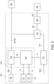
- reference numeral 100 indicates as a whole an electronic system for controlling a braking system of a vehicle, hereinafter also electronic system or simply system, according to the present invention.
- vehicle means any vehicle or motorcycle, also of commercial type, having two, three, four or more wheels.
- braking system means the whole of all the components (mechanical and/or electric or electronic, also the brake fluid) which contribute to generating the service braking of a vehicle or to generating the parking-braking of a vehicle.
- the system 100 comprises a vehicle control module 101.
- the vehicle control module 101 e.g. a hardware module or software logic in a main hardware module, is configured, as one of its intended tasks, to receive a braking request RF (deceleration request).
- a braking request RF deceleration request
- Such a braking request RF may come from a brake pedal (not shown in the figures) which can be actuated by the vehicle driver and, for example, may be processed by a logic of the EBD (Electronic Brake-force Distribution) type (not shown in the figures) implemented by the vehicle control module 101 or may come from an automatic driver assistant logic of the vehicle, e.g. a logic of the AEB (Autonomous Emergency Brake) type (also not shown in the figures).
- EBD Electronic Brake-force Distribution
- AEB Automatic Emergency Brake
- the vehicle control module 101 is further configured to receive first input information I1 representative of the vehicle.
- first input information I1 representative of the vehicle means information detected and/or estimated coming from detecting devices (real or virtual sensors) installed on the vehicle, i.e. at the corners (front or rear of the vehicle), but not necessarily related to the braking system of the vehicle.
- Examples of such first input information I1 representative of the vehicle are:
- the vehicle control module 101 is configured to determine first intermediate information I1' on the basis of said first input information I1.
- Such first intermediate information I1' is mathematical processing of such first input information I1, e.g. a derivative, a filtering (e.g. mean, median, FIR filter, IIR filter and so on).
- a filtering e.g. mean, median, FIR filter, IIR filter and so on.
- the first intermediate information I1' comprises:
- the vehicle control module 101 is configured to determine a reference force value FS on the basis of the first input information I1 and of the braking request RF.
- the system 100 further comprises a first plurality P1 of detecting devices operationally associated with a corner of a vehicle.
- the first plurality P1 of detecting devices are configured to detect second input information I2 representative of the braking system at a vehicle corner.
- second input information I2 representative of the braking system at a vehicle corner means information located at the vehicle corner.
- the first plurality P1 of detecting devices comprises a first plurality P1' of physical sensors or switches, e.g. such as, for example, position sensors, electrical voltage sensors, electrical current sensors, temperature sensors and so on.
- the second input information I2 representative of the braking system is, for example:
- the first plurality P1 of detecting devices may comprise, in addition to the first plurality P1' of physical sensors, a second plurality P1" of force sensors or switches, which can be made for example in hardware or by implementing a software logic.
- Examples of such force sensors or switches are a start of load force switch, a force sensor with a limited range in the first part of the stroke of the electro-mechanical actuator piston, a software estimator passing from the gap zone (no-load position) to the load zone by the electro-mechanical actuator piston.
- the second input information I1 representative of the braking system comprises, for example, information representative of the start of the force step from the electro-mechanical actuator, i.e. information (for example, a flag) representative of the start of the load step, in which the electro-mechanical actuator piston starts to apply force and moves from a no-load position to a position in which it starts to load on the brake caliper.
- the information representative of the start of the force step by the electro-mechanical actuator is determined by a force sensor or switch P1" by comparing quantities, such as speed, acceleration, gradients, current, position, application time or derivatives of these quantities, with their respective reference thresholds.
- system 100 further comprises a force estimation and validation module 102.
- the force estimation and validation module 102 e.g. a hardware module or a software logic in a main hardware module, is configured to determine a value of an estimated force ST on the basis of said first intermediate information I1' and said first input information I2.
- the force estimation and validation module 102 is further configured to determine a control quantity GC.
- the system 100 further comprises a brake control module 103.
- the brake control module 103 e.g. a hardware module or software logic in a main hardware module, is configured to determine a control signal SC of an electro-mechanical actuator of a brake caliper of the braking system (diagrammatically shown outside the system 100 and indicated by reference A) based on the control quantity GC and of the reference force value FS.
- the SC control signal is, for example, the reference value (set point) of electrical current or electrical voltage (PWM) to be supplied to the electro-mechanical actuator AE of the brake caliper.
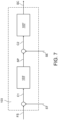
- control signal SC A calculation example of the control signal SC will be provided below with reference to figure 7 .
- the brake control module 103 is configured to provide such a control signal SC to the electro-mechanical actuator AE.
- system 100 further comprises an electronic drive module DR for the electro-mechanical actuator.
- the brake control module 103 is configured to provide the electro-mechanical actuator AE with the control signal SC by means of the electronic drive module DR.
- the drive module DR is configured to receive the control signal SC, thus a braking request level (percentage/PWM), whereby generating a drive signal SC' to be provided to the AE electro-mechanical actuator, e.g. an electric current drive to be provided to the electric motor to move the electro-mechanical actuator AE.
- the force estimation and validation module 102 comprises a first force estimation submodule 104.
- the first force estimation submodule 104 e.g. a hardware module or a software logic within a main hardware module, is configured to determine the value of an estimated force ST on the basis of said first intermediate information I1' and said first input information I2.
- the first force estimate submodule 104 is configured to determine the control quantity GC on the basis of the estimated force value ST.
- the vehicle control module 101 is configured to provide the determined reference force value FS, on the basis of the first input information I1 and of the braking request RF, directly to the brake control module 103.
- control braking control module 103 is configured to determine the control signal SC of an electro-mechanical actuator AE of a brake caliper of the braking system on the basis of the control quantity GC and of the reference force value FS.
- control quantity representative of the validated force value is the estimated force value which is still validated by the first force estimation submodule so as to ensure a sufficient robust force level for controlling the electro-mechanical actuator AE.
- Such an estimated force value is validated by the feedback received from other sensors and/or the dynamic response of the vehicle.
- the first force estimation submodule 104 is configured to provide the estimated force value to a vehicle diagnostics and safety module DS with which the vehicle is equipped.
- the vehicle diagnostics and safety module DS e.g. a hardware module or software logic module in a main hardware module, is diagrammatically shown in figure 1 outside the system 100.
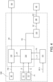
- the force estimation and validation module 102 comprises a first force estimation submodule 104 and a second force validation submodule 105.
- the first force estimation submodule 104 is configured to determine an estimated force value ST on the basis of said first intermediate information I1' and said second input information I2.
- system 100 further comprises at least one force sensor SF operatively connected to the second force validation submodule 105.
- the at least one force sensor SF has a low ASIL (Automotive Safety Integrity Level) and is therefore low cost.
- Examples of said at least one force sensor SF are force sensors with variable robustness from QM (Quality Management) or ASIL type safety level reduced from A to C, such as strain gage, piezo, magneto-elastic and so forth.
- the at least one force sensor SF is configured to detect a force value FM applied by the electro-mechanical actuator AE onto the brake caliper of the braking system.
- the second force validation submodule 105 e.g. a hardware module or software logic in a main hardware module, is configured to determine the control quantity GC on the basis of the estimated force value ST and of the detected force value FM applied by the electro-mechanical actuator AE onto the brake caliper of the braking system.
- the first force estimation submodule 104 is configured to determine the estimated force value ST without using the information provided by said at least one force sensor SF, i.e. without using the detected force value FM.
- the estimated force value ST is instead used by the second force validation submodule 105 to validate the detected force value FM coming from at least one force sensor SF.
- the system 100 by having redundant force information, allows the lowering of the safety level requirements of the at least one force sensor SF which, as mentioned above, may have a low ASIL type safety level, therefore low cost.
- the second force validation submodule 105 is configured to compare the estimated force value ST and the force value FM detected by at least one force sensor SF and to establish from the result of such a comparison, performed on the basis of acceptance thresholds, how correct is the force value FM detected by at least one force sensor SF with respect to the estimated force value ST and consequently to perform a mathematical processing of the two values, e.g. simple average, weighted average or other types of filtering.
- the vehicle control module 101 is further configured to provide the reference force value FS determined on the basis of the first input information I1 and of the braking request RF, directly to the brake control module 103.
- the braking control module 103 is configured to determine a control signal SC of an electro-mechanical actuator AE of a brake caliper of the braking system on the basis of the control quantity GC and of the determined reference force value FS.
- control quantity GC is the validated force value VD.
- the second force validation submodule 105 is configured to provide the validated force value VD to a vehicle diagnostics and safety module DS with which the vehicle is equipped.
- the vehicle diagnostics and safety module DS e.g. a hardware module or software logic module in a main hardware module, is diagrammatically shown in figure 2 outside the system 100.
- the vehicle control module 101 is configured to provide the reference force value FS, determined on the basis of the first input information I1 and of the braking request RF, directly to the first force estimation submodule 104.
- the first force estimation submodule 104 is configured to determine the control quantity GC on the basis of the determined reference force value FS.
- the validated force value VD is the estimated force value ST.
- control quantity GC is a position value of the electro-mechanical actuator AE of the brake caliper of the braking system corresponding to the determined reference force value.
- control braking control module 103 is configured to determine the control signal SC of an electro-mechanical actuator AE of a brake caliper of the braking system on the basis of the control quantity GC.
- the first force estimation submodule 104 is configured to provide the estimated force value ST to a vehicle diagnostics and safety module DS with which the vehicle is equipped.
- the vehicle diagnostics and safety module DS e.g. a hardware module or software logic module in a main hardware module, is diagrammatically shown in figure 3 outside the system 100.
- the vehicle control module 101 is configured to provide the reference force value FS determined on the basis of the first input information I1 and of the braking request RF, directly to the first force estimation submodule 104.
- the first force estimation submodule 104 is configured to determine the control quantity GC based on the estimated force value ST and the determined reference force value FS.
- control quantity GC is a position value of the electro-mechanical actuator AE of the brake caliper of the braking system corresponding to the determined reference force value FS.
- system 100 further comprises at least one force sensor SF operatively connected to the second force validation submodule 105.
- the at least one force sensor SF has a low ASIL (Automotive Safety Integrity Level) and is therefore low cost.
- Examples of said at least one force sensor SF are force sensors with variable robustness from QM (Quality Management) or ASIL type safety level reduced from A to C, such as strain gage, piezo, magneto-elastic and so forth.
- the at least one force sensor SF is configured to detect a force value FM applied by the electro-mechanical actuator AE onto the brake caliper of the braking system.
- the second force validation submodule 105 is configured to determine the validated force value VD on the basis of the estimated force value ST and of the detected force value FM applied by the electro-mechanical actuator AE onto the brake caliper of the braking system.
- the second force estimation submodule 105 is configured to provide the validated force value VD to a vehicle diagnostics and safety module DS with which the vehicle is equipped.
- the vehicle diagnostics and safety module DS e.g. a hardware module or software logic module in a main hardware module, is diagrammatically shown in figure 4 outside the system 100.
- each described module may be, for example, a hardware module or a software logic in a main hardware module and these modules can be organized according to different hardware and/or logic architectures.
- a first example of architecture could comprise a first electronic control unit ECU1 configured as master unit of the rear axle of the vehicle and a second electronic control unit ECU2, operationally connected to the first electronic control unit EC1, configured as slave unit of the front axle of the vehicle.
- the first electronic control unit EC1 may comprise:
- the second electronic control unit EC2 may comprise:
- a second example of architecture may comprise:
- the first electronic control unit EC1 may comprise:
- a method 500 for controlling a braking system of a vehicle according to the present invention will be described with reference to the aforesaid figures and to the block chart in figure 5 .
- the method 500 comprises a symbolic step of starting STR.
- the method 500 comprises a step of receiving 501, by a vehicle control module 101, a braking request RF.
- control module 101 The control module 101 and the RF braking request were described above.
- the method 500 further comprises a step of receiving 502, by the vehicle control module 101, first input information I1 representative of the vehicle.
- the method 500 further comprises a step of determining 503, by the vehicle control module 101, first intermediate information I1' on the basis of said first input information I1.
- the first intermediate information I1' was described above.
- the method 500 comprises a step of determining 504, by the vehicle control module 101, a reference force value FS on the basis of the first input information I1 and of the braking request RF.
- the vehicle control module 101 determines, by means of a respective processing block 101', the reference force value FS as a function of the following information representative of the vehicle dynamics, i.e.:
- the method 500 further comprises a step of detecting 505, by a first plurality P1 of the detecting devices operatively associated with a corner of a vehicle, second input information I2 representative of the braking system at the corner of the vehicle.
- the first plurality of detecting devices P1 and the second input information I2 were described above.
- the method 500 further comprises a step of determining 506, by a force estimation and validation module 102, an estimated force value ST on the basis of said first intermediate information I1' and said second input information I2.
- the estimation and validation module 102 was described above.
- the method 500 further comprises a step of determining 507, by the force estimation and validation module 102, a control quantity GC.
- control quantity was described above but will also be described below with reference to different embodiments of the method 500.
- the method 500 in figure 5 further comprises a step of determining 508, by a braking control module 103, a control signal SC of an electro-mechanical actuator AE of a brake caliper of the braking system on the basis of the control quantity GC and of the reference force value FS.
- the brake control module 103, the control signal SC of an electro-mechanical actuator AE of a brake caliper of the braking system and the electro-mechanical actuator AE have been described above.
- control signal SC A calculation example of the control signal SC will be described below with reference to figure 7 .
- the brake control module 103 compares the reference force value FS with the estimated force value ST and the result of such first comparison C1 is sent as input to a first processing block 103', e.g. a force controller, which generates a reference speed value SP as a function of the first comparison C1.
- a first processing block 103' e.g. a force controller, which generates a reference speed value SP as a function of the first comparison C1.
- the brake control module 103 compares the reference speed value SP with an estimated speed value SE and the result of this second comparison C2 is sent as input to a second processing block 103", e.g. a speed controller, which generates the control signal SC to be sent to the electro-mechanical actuator AE as a function of the result of the second comparison C2.
- a second processing block 103 e.g. a speed controller, which generates the control signal SC to be sent to the electro-mechanical actuator AE as a function of the result of the second comparison C2.
- the estimated speed value SE is determined, by the first force estimation submodule 104, on the basis of the second input information I2 provided by the first plurality P1 of detecting devices.
- the method 500 further comprises a step of providing 509, by the control module braking 103, said control signal SC to said electro-mechanical actuator AE.
- the method 500 thus ends with a symbolic step of ending ED.
- the force estimation and validation module 102 comprises a first force estimation submodule 104 (already described above).
- the step of determining 507, by the force estimation and validation module 102, a control quantity GC comprises the steps of:
- the method further comprises the steps of:
- the method 500 further comprises a step of providing 604, by the first force estimation submodule 104, the estimated force value ST to a vehicle diagnostics and safety module DS with which the vehicle is equipped.
- the force estimation and validation module 102 comprises a first force estimation submodule 104 and a second force validation submodule 105 (already described above).
- the step of determining 507, by the force estimation and validation module 104, a control quantity GC comprises the steps of:
- the method 500 comprises the steps of:
- the method 500 comprises a step of providing 705, by the second force validation submodule 105, the validated force value VD to a vehicle diagnostics and safety module DS (already described above) with which the vehicle is equipped.
- the method 500 comprises the steps of:
- the validated force value VD is the estimated force value ST.
- control quantity GC is a position value of the electro-mechanical actuator AE of the brake caliper of the braking system corresponding to the determined reference force value FS.
- the method 500 further comprises a step of determining 802, by a braking control module 103, the control signal SC of the electro-mechanical actuator AE of a brake caliper of the braking system on the basis of the control quantity GC.
- the method 500 comprises a step of providing 604, by the first force estimation submodule 104, the estimated force value ST to a vehicle diagnostics and safety module DS with which the vehicle is equipped.
- the method 500 comprises the steps of:
- control quantity GC is a position value of the electro-mechanical actuator AE of the brake caliper of the braking system corresponding to the determined reference force value FS.
- the method 500 further comprises the steps of:
- the method 500 comprises a step of providing 904, by the second force validation submodule 105, the validated force value VD to a vehicle diagnostics and safety module DS (described above) with which the vehicle is equipped.
- a first example relates to the use of a logic/model based on a theoretical stiffness curve Fx, i.e. a relation between the force F applied by the electro-mechanical actuator AE and the position P of the piston of the electro-mechanical actuator AE.
- stiffness curve Fx is shown in the chart in figure 8 .
- a second example relates to the use of a logic/model based on a mechanical equation (dynamic model) of the electro-mechanical actuator AE.
- the estimated force value ST is a function of the following quantities:
- a third example relates to the use of a logic/model based on models with parameter estimation.
- a last example relates to the use of a logic/model based on an adaptive model by means of machine learning techniques for real-time variation of the parameters of the estimation techniques according to the examples described above.
- the estimated force value ST can be used in two different ways:
- the method and system thereof which are the object of this invention allows controlling a braking system with BBW type electronic braking system by estimating the force without using the traditionally employed sensors, typically very reliable but also very expensive, but exploiting a hardware/software model estimating the force which makes use of the measurements of other sensors installed on the vehicle.
- the advantage of the method and of the system thereof according to the present invention is to be able to partially replace, or in some cases eliminate, the sensors traditionally used in brake calipers and to use sensors having lower quality and reliability requirements instead, which are for this reason less expensive, ensuring the same required safety level and allowing a reduction in system costs.
- the method and the system according to the present invention considering the possibility of being able to reduce the requirements of the force sensor to be applied or even to eliminate the force sensor itself, advantageously allow a considerable reduction in terms of weight and size of the electro-mechanical actuator which can be used (as well as cost as already mentioned).
- teachings of the present invention may be used to make a method and system thereof for estimating the pressure in a hydraulic system and closed-loop control of the pressure to be applied to an electro-
Landscapes
- Engineering & Computer Science (AREA)
- Transportation (AREA)
- Mechanical Engineering (AREA)
- Regulating Braking Force (AREA)
- Valves And Accessory Devices For Braking Systems (AREA)
- Braking Systems And Boosters (AREA)
Applications Claiming Priority (2)
| Application Number | Priority Date | Filing Date | Title |
|---|---|---|---|
| IT102018000009105A IT201800009105A1 (it) | 2018-10-02 | 2018-10-02 | Metodo di controllo di un impianto frenante di un veicolo e relativo sistema |
| PCT/IB2019/058279 WO2020070613A1 (en) | 2018-10-02 | 2019-09-30 | Method for controlling a braking system of a vehicle and system thereof |
Publications (2)
| Publication Number | Publication Date |
|---|---|
| EP3860891A1 EP3860891A1 (en) | 2021-08-11 |
| EP3860891B1 true EP3860891B1 (en) | 2023-08-02 |
Family
ID=65244438
Family Applications (1)
| Application Number | Title | Priority Date | Filing Date |
|---|---|---|---|
| EP19794647.8A Active EP3860891B1 (en) | 2018-10-02 | 2019-09-30 | Method for controlling a braking system of a vehicle and system thereof |
Country Status (7)
| Country | Link |
|---|---|
| US (1) | US20220017049A1 (zh) |
| EP (1) | EP3860891B1 (zh) |
| JP (1) | JP7498168B2 (zh) |
| CN (1) | CN113165616B (zh) |
| ES (1) | ES2962146T3 (zh) |
| IT (1) | IT201800009105A1 (zh) |
| WO (1) | WO2020070613A1 (zh) |
Families Citing this family (3)
| Publication number | Priority date | Publication date | Assignee | Title |
|---|---|---|---|---|
| DE102020214518A1 (de) | 2020-11-18 | 2022-03-17 | Vitesco Technologies GmbH | Sensoranordnung und Verfahren zum Erfassen der Last und einer Laständerung eines Fahrzeugs |
| DE102020214522B3 (de) | 2020-11-18 | 2022-01-13 | Vitesco Technologies GmbH | Verfahren und Sensoranordnung zum Ermitteln einer tatsächlichen Einbauposition eines an einer Fahrzeugachse eines Fahrzeugs anbringbaren Lastsensors |
| DE102020134639B4 (de) | 2020-12-22 | 2022-10-27 | Continental Automotive Technologies GmbH | Verfahren zum Ermitteln eines Fehlers einer Gewichtserfassungsvorrichtung und eines Gewichtserfassungssystem eines Fahrzeugs sowie eine Gewichtserfassungsvorrichtung und ein Gewichtserfassungssystem für ein Fahrzeug |
Family Cites Families (15)
| Publication number | Priority date | Publication date | Assignee | Title |
|---|---|---|---|---|
| JP4345416B2 (ja) * | 2003-06-03 | 2009-10-14 | トヨタ自動車株式会社 | 車輌の制動力制御装置 |
| JP4834397B2 (ja) * | 2005-12-15 | 2011-12-14 | 日立オートモティブシステムズ株式会社 | 車両のブレーキ制御装置 |
| US8328297B2 (en) * | 2006-06-06 | 2012-12-11 | Honda Motor Co., Ltd. | Brake system |
| ITTO20060735A1 (it) * | 2006-10-13 | 2008-04-14 | St Microelectronics Srl | Sistema e metodo di controllo autoadattativo di un freno elettromeccanico |
| US20130133965A1 (en) * | 2011-11-30 | 2013-05-30 | Martin T. Books | Vehicle braking management for a hybrid power train system |
| JP5983476B2 (ja) * | 2013-03-15 | 2016-08-31 | 株式会社アドヴィックス | 車両の電動制動装置 |
| DE102013205245A1 (de) * | 2013-03-25 | 2014-09-25 | Continental Teves Ag & Co. Ohg | Fahrzeugreferenzgeschwindigkeitsbestimmungsverfahren und Fahrzeugsteuergerät mit einem solchen Verfahren |
| WO2014181397A1 (ja) * | 2013-05-08 | 2014-11-13 | トヨタ自動車株式会社 | 車両のブレーキ装置 |
| EP3009314B8 (en) * | 2014-10-17 | 2021-09-01 | BREMBO S.p.A. | Automatically controlled braking sytem for motor vehicles and related method of actuating and controlling such a system |
| GB2536008B (en) * | 2015-03-03 | 2019-06-12 | Jaguar Land Rover Ltd | Vehicle state estimation apparatus and method |
| DE102015113587A1 (de) * | 2015-08-17 | 2017-02-23 | Knorr-Bremse Systeme für Nutzfahrzeuge GmbH | Linearsensor für eine Bremse |
| JP6644502B2 (ja) * | 2015-09-10 | 2020-02-12 | Ntn株式会社 | 電動ブレーキ装置 |
| US10144402B2 (en) * | 2016-08-29 | 2018-12-04 | GM Global Technology Operations LLC | Brake-by-wire system |
| US20180056964A1 (en) * | 2016-08-31 | 2018-03-01 | GM Global Technology Operations LLC | Brake-by-wire system |
| US10173661B2 (en) * | 2016-11-23 | 2019-01-08 | GM Global Technology Operations LLC | Brake fade management system for a brake-by-wire system |
-
2018
- 2018-10-02 IT IT102018000009105A patent/IT201800009105A1/it unknown
-
2019
- 2019-09-30 ES ES19794647T patent/ES2962146T3/es active Active
- 2019-09-30 WO PCT/IB2019/058279 patent/WO2020070613A1/en unknown
- 2019-09-30 JP JP2021518105A patent/JP7498168B2/ja active Active
- 2019-09-30 EP EP19794647.8A patent/EP3860891B1/en active Active
- 2019-09-30 US US17/281,695 patent/US20220017049A1/en active Pending
- 2019-09-30 CN CN201980078730.4A patent/CN113165616B/zh active Active
Also Published As
| Publication number | Publication date |
|---|---|
| US20220017049A1 (en) | 2022-01-20 |
| ES2962146T3 (es) | 2024-03-15 |
| WO2020070613A1 (en) | 2020-04-09 |
| IT201800009105A1 (it) | 2020-04-02 |
| JP7498168B2 (ja) | 2024-06-11 |
| EP3860891A1 (en) | 2021-08-11 |
| CN113165616B (zh) | 2024-08-30 |
| CN113165616A (zh) | 2021-07-23 |
| JP2022504083A (ja) | 2022-01-13 |
Similar Documents
| Publication | Publication Date | Title |
|---|---|---|
| EP3860891B1 (en) | Method for controlling a braking system of a vehicle and system thereof | |
| EP3472008B1 (en) | A wheel controller for a vehicle | |
| EP2112053B1 (en) | Yaw stability control system | |
| US8442737B2 (en) | Method for operating a vehicle brake system and vehicle brake system | |
| US8504273B2 (en) | Coefficient of friction based limitation of the torque of a vehicle control loop | |
| EP2612796A1 (en) | Braking force control device for vehicle | |
| KR101732832B1 (ko) | 차량 운동 역학 제어 방법 | |
| US9895978B2 (en) | Braking force control method for vehicle | |
| US8812211B2 (en) | Adapting a braking process | |
| CN103380034A (zh) | 用于识别和校正车辆参考速度的方法以及车辆系统 | |
| US20200086885A1 (en) | Vehicle Control Device | |
| DE102014003992B4 (de) | System und Verfahren zur Antriebs- und Bremsmomentregelung in Elektrofahrzeugen mit Einzelradantrieb | |
| CN112298162A (zh) | 车辆用干扰应对系统 | |
| CN114537345A (zh) | 制动方法、制动系统以及车辆 | |
| JP2007106338A (ja) | 車輌の車体速度推定装置 | |
| CN112298163A (zh) | 车辆用干扰应对系统 | |
| JP2006501094A5 (zh) | ||
| JP2006501094A (ja) | 操舵トルクを決定する方法 | |
| JP6801113B2 (ja) | 車両のブレーキシステムの電気機械式ブレーキ倍力装置を動作させるための制御装置及び方法 | |
| Kant | Sensotronic brake control (SBC) | |
| EP2565091B1 (en) | Method and system for controlling brake fluid pressure | |
| JP5495027B2 (ja) | 車輪の制動力推定装置、及び、該装置を備えた車両の運動制御装置 | |
| JPWO2014188923A1 (ja) | 車両の挙動制御装置 | |
| JP2015216724A (ja) | 制駆動力制御装置 | |
| US20100320833A1 (en) | Method and device for stabilizing a vehicle |
Legal Events
| Date | Code | Title | Description |
|---|---|---|---|
| STAA | Information on the status of an ep patent application or granted ep patent |
Free format text: STATUS: UNKNOWN |
|
| STAA | Information on the status of an ep patent application or granted ep patent |
Free format text: STATUS: THE INTERNATIONAL PUBLICATION HAS BEEN MADE |
|
| PUAI | Public reference made under article 153(3) epc to a published international application that has entered the european phase |
Free format text: ORIGINAL CODE: 0009012 |
|
| STAA | Information on the status of an ep patent application or granted ep patent |
Free format text: STATUS: REQUEST FOR EXAMINATION WAS MADE |
|
| 17P | Request for examination filed |
Effective date: 20210330 |
|
| AK | Designated contracting states |
Kind code of ref document: A1 Designated state(s): AL AT BE BG CH CY CZ DE DK EE ES FI FR GB GR HR HU IE IS IT LI LT LU LV MC MK MT NL NO PL PT RO RS SE SI SK SM TR |
|
| RAP3 | Party data changed (applicant data changed or rights of an application transferred) |
Owner name: BREMBO S.P.A. |
|
| DAV | Request for validation of the european patent (deleted) | ||
| DAX | Request for extension of the european patent (deleted) | ||
| GRAP | Despatch of communication of intention to grant a patent |
Free format text: ORIGINAL CODE: EPIDOSNIGR1 |
|
| STAA | Information on the status of an ep patent application or granted ep patent |
Free format text: STATUS: GRANT OF PATENT IS INTENDED |
|
| INTG | Intention to grant announced |
Effective date: 20230331 |
|
| GRAS | Grant fee paid |
Free format text: ORIGINAL CODE: EPIDOSNIGR3 |
|
| GRAA | (expected) grant |
Free format text: ORIGINAL CODE: 0009210 |
|
| STAA | Information on the status of an ep patent application or granted ep patent |
Free format text: STATUS: THE PATENT HAS BEEN GRANTED |
|
| P01 | Opt-out of the competence of the unified patent court (upc) registered |
Effective date: 20230526 |
|
| AK | Designated contracting states |
Kind code of ref document: B1 Designated state(s): AL AT BE BG CH CY CZ DE DK EE ES FI FR GB GR HR HU IE IS IT LI LT LU LV MC MK MT NL NO PL PT RO RS SE SI SK SM TR |
|
| REG | Reference to a national code |
Ref country code: GB Ref legal event code: FG4D |
|
| REG | Reference to a national code |
Ref country code: CH Ref legal event code: EP |
|
| REG | Reference to a national code |
Ref country code: DE Ref legal event code: R096 Ref document number: 602019034147 Country of ref document: DE |
|
| REG | Reference to a national code |
Ref country code: IE Ref legal event code: FG4D |
|
| REG | Reference to a national code |
Ref country code: LT Ref legal event code: MG9D |
|
| REG | Reference to a national code |
Ref country code: NL Ref legal event code: MP Effective date: 20230802 |
|
| REG | Reference to a national code |
Ref country code: AT Ref legal event code: MK05 Ref document number: 1594361 Country of ref document: AT Kind code of ref document: T Effective date: 20230802 |
|
| PG25 | Lapsed in a contracting state [announced via postgrant information from national office to epo] |
Ref country code: GR Free format text: LAPSE BECAUSE OF FAILURE TO SUBMIT A TRANSLATION OF THE DESCRIPTION OR TO PAY THE FEE WITHIN THE PRESCRIBED TIME-LIMIT Effective date: 20231103 |
|
| PGFP | Annual fee paid to national office [announced via postgrant information from national office to epo] |
Ref country code: ES Payment date: 20231005 Year of fee payment: 5 |
|
| PG25 | Lapsed in a contracting state [announced via postgrant information from national office to epo] |
Ref country code: IS Free format text: LAPSE BECAUSE OF FAILURE TO SUBMIT A TRANSLATION OF THE DESCRIPTION OR TO PAY THE FEE WITHIN THE PRESCRIBED TIME-LIMIT Effective date: 20231202 |
|
| PG25 | Lapsed in a contracting state [announced via postgrant information from national office to epo] |
Ref country code: SE Free format text: LAPSE BECAUSE OF FAILURE TO SUBMIT A TRANSLATION OF THE DESCRIPTION OR TO PAY THE FEE WITHIN THE PRESCRIBED TIME-LIMIT Effective date: 20230802 Ref country code: RS Free format text: LAPSE BECAUSE OF FAILURE TO SUBMIT A TRANSLATION OF THE DESCRIPTION OR TO PAY THE FEE WITHIN THE PRESCRIBED TIME-LIMIT Effective date: 20230802 Ref country code: PT Free format text: LAPSE BECAUSE OF FAILURE TO SUBMIT A TRANSLATION OF THE DESCRIPTION OR TO PAY THE FEE WITHIN THE PRESCRIBED TIME-LIMIT Effective date: 20231204 Ref country code: NO Free format text: LAPSE BECAUSE OF FAILURE TO SUBMIT A TRANSLATION OF THE DESCRIPTION OR TO PAY THE FEE WITHIN THE PRESCRIBED TIME-LIMIT Effective date: 20231102 Ref country code: NL Free format text: LAPSE BECAUSE OF FAILURE TO SUBMIT A TRANSLATION OF THE DESCRIPTION OR TO PAY THE FEE WITHIN THE PRESCRIBED TIME-LIMIT Effective date: 20230802 Ref country code: LV Free format text: LAPSE BECAUSE OF FAILURE TO SUBMIT A TRANSLATION OF THE DESCRIPTION OR TO PAY THE FEE WITHIN THE PRESCRIBED TIME-LIMIT Effective date: 20230802 Ref country code: LT Free format text: LAPSE BECAUSE OF FAILURE TO SUBMIT A TRANSLATION OF THE DESCRIPTION OR TO PAY THE FEE WITHIN THE PRESCRIBED TIME-LIMIT Effective date: 20230802 Ref country code: IS Free format text: LAPSE BECAUSE OF FAILURE TO SUBMIT A TRANSLATION OF THE DESCRIPTION OR TO PAY THE FEE WITHIN THE PRESCRIBED TIME-LIMIT Effective date: 20231202 Ref country code: HR Free format text: LAPSE BECAUSE OF FAILURE TO SUBMIT A TRANSLATION OF THE DESCRIPTION OR TO PAY THE FEE WITHIN THE PRESCRIBED TIME-LIMIT Effective date: 20230802 Ref country code: GR Free format text: LAPSE BECAUSE OF FAILURE TO SUBMIT A TRANSLATION OF THE DESCRIPTION OR TO PAY THE FEE WITHIN THE PRESCRIBED TIME-LIMIT Effective date: 20231103 Ref country code: FI Free format text: LAPSE BECAUSE OF FAILURE TO SUBMIT A TRANSLATION OF THE DESCRIPTION OR TO PAY THE FEE WITHIN THE PRESCRIBED TIME-LIMIT Effective date: 20230802 Ref country code: AT Free format text: LAPSE BECAUSE OF FAILURE TO SUBMIT A TRANSLATION OF THE DESCRIPTION OR TO PAY THE FEE WITHIN THE PRESCRIBED TIME-LIMIT Effective date: 20230802 |
|
| PG25 | Lapsed in a contracting state [announced via postgrant information from national office to epo] |
Ref country code: PL Free format text: LAPSE BECAUSE OF FAILURE TO SUBMIT A TRANSLATION OF THE DESCRIPTION OR TO PAY THE FEE WITHIN THE PRESCRIBED TIME-LIMIT Effective date: 20230802 |
|
| REG | Reference to a national code |
Ref country code: ES Ref legal event code: FG2A Ref document number: 2962146 Country of ref document: ES Kind code of ref document: T3 Effective date: 20240315 |
|
| PG25 | Lapsed in a contracting state [announced via postgrant information from national office to epo] |
Ref country code: SM Free format text: LAPSE BECAUSE OF FAILURE TO SUBMIT A TRANSLATION OF THE DESCRIPTION OR TO PAY THE FEE WITHIN THE PRESCRIBED TIME-LIMIT Effective date: 20230802 Ref country code: RO Free format text: LAPSE BECAUSE OF FAILURE TO SUBMIT A TRANSLATION OF THE DESCRIPTION OR TO PAY THE FEE WITHIN THE PRESCRIBED TIME-LIMIT Effective date: 20230802 Ref country code: EE Free format text: LAPSE BECAUSE OF FAILURE TO SUBMIT A TRANSLATION OF THE DESCRIPTION OR TO PAY THE FEE WITHIN THE PRESCRIBED TIME-LIMIT Effective date: 20230802 Ref country code: DK Free format text: LAPSE BECAUSE OF FAILURE TO SUBMIT A TRANSLATION OF THE DESCRIPTION OR TO PAY THE FEE WITHIN THE PRESCRIBED TIME-LIMIT Effective date: 20230802 Ref country code: CZ Free format text: LAPSE BECAUSE OF FAILURE TO SUBMIT A TRANSLATION OF THE DESCRIPTION OR TO PAY THE FEE WITHIN THE PRESCRIBED TIME-LIMIT Effective date: 20230802 Ref country code: SK Free format text: LAPSE BECAUSE OF FAILURE TO SUBMIT A TRANSLATION OF THE DESCRIPTION OR TO PAY THE FEE WITHIN THE PRESCRIBED TIME-LIMIT Effective date: 20230802 |
|
| REG | Reference to a national code |
Ref country code: CH Ref legal event code: PL |
|
| REG | Reference to a national code |
Ref country code: DE Ref legal event code: R097 Ref document number: 602019034147 Country of ref document: DE |
|
| PG25 | Lapsed in a contracting state [announced via postgrant information from national office to epo] |
Ref country code: LU Free format text: LAPSE BECAUSE OF NON-PAYMENT OF DUE FEES Effective date: 20230930 |
|
| REG | Reference to a national code |
Ref country code: BE Ref legal event code: MM Effective date: 20230930 |
|
| PG25 | Lapsed in a contracting state [announced via postgrant information from national office to epo] |
Ref country code: LU Free format text: LAPSE BECAUSE OF NON-PAYMENT OF DUE FEES Effective date: 20230930 Ref country code: IT Free format text: LAPSE BECAUSE OF FAILURE TO SUBMIT A TRANSLATION OF THE DESCRIPTION OR TO PAY THE FEE WITHIN THE PRESCRIBED TIME-LIMIT Effective date: 20230802 Ref country code: MC Free format text: LAPSE BECAUSE OF FAILURE TO SUBMIT A TRANSLATION OF THE DESCRIPTION OR TO PAY THE FEE WITHIN THE PRESCRIBED TIME-LIMIT Effective date: 20230802 |
|
| PLBE | No opposition filed within time limit |
Free format text: ORIGINAL CODE: 0009261 |
|
| STAA | Information on the status of an ep patent application or granted ep patent |
Free format text: STATUS: NO OPPOSITION FILED WITHIN TIME LIMIT |
|
| REG | Reference to a national code |
Ref country code: IE Ref legal event code: MM4A |
|
| PG25 | Lapsed in a contracting state [announced via postgrant information from national office to epo] |
Ref country code: IE Free format text: LAPSE BECAUSE OF NON-PAYMENT OF DUE FEES Effective date: 20230930 |
|
| 26N | No opposition filed |
Effective date: 20240503 |
|
| PG25 | Lapsed in a contracting state [announced via postgrant information from national office to epo] |
Ref country code: CH Free format text: LAPSE BECAUSE OF NON-PAYMENT OF DUE FEES Effective date: 20230930 |
|
| PG25 | Lapsed in a contracting state [announced via postgrant information from national office to epo] |
Ref country code: IE Free format text: LAPSE BECAUSE OF NON-PAYMENT OF DUE FEES Effective date: 20230930 Ref country code: CH Free format text: LAPSE BECAUSE OF NON-PAYMENT OF DUE FEES Effective date: 20230930 Ref country code: SI Free format text: LAPSE BECAUSE OF FAILURE TO SUBMIT A TRANSLATION OF THE DESCRIPTION OR TO PAY THE FEE WITHIN THE PRESCRIBED TIME-LIMIT Effective date: 20230802 |
|
| PG25 | Lapsed in a contracting state [announced via postgrant information from national office to epo] |
Ref country code: BE Free format text: LAPSE BECAUSE OF NON-PAYMENT OF DUE FEES Effective date: 20230930 |
|
| PGFP | Annual fee paid to national office [announced via postgrant information from national office to epo] |
Ref country code: DE Payment date: 20240911 Year of fee payment: 6 |
|
| PGFP | Annual fee paid to national office [announced via postgrant information from national office to epo] |
Ref country code: GB Payment date: 20240920 Year of fee payment: 6 |
|
| PGFP | Annual fee paid to national office [announced via postgrant information from national office to epo] |
Ref country code: FR Payment date: 20240829 Year of fee payment: 6 |