EP3859102A1 - Türschliesssystem - Google Patents
Türschliesssystem Download PDFInfo
- Publication number
- EP3859102A1 EP3859102A1 EP21151279.3A EP21151279A EP3859102A1 EP 3859102 A1 EP3859102 A1 EP 3859102A1 EP 21151279 A EP21151279 A EP 21151279A EP 3859102 A1 EP3859102 A1 EP 3859102A1
- Authority
- EP
- European Patent Office
- Prior art keywords
- pin
- coupling
- door
- door handle
- locking system
- Prior art date
- Legal status (The legal status is an assumption and is not a legal conclusion. Google has not performed a legal analysis and makes no representation as to the accuracy of the status listed.)
- Granted
Links
Images


Classifications
-
- E—FIXED CONSTRUCTIONS
- E05—LOCKS; KEYS; WINDOW OR DOOR FITTINGS; SAFES
- E05B—LOCKS; ACCESSORIES THEREFOR; HANDCUFFS
- E05B13/00—Devices preventing the key or the handle or both from being used
- E05B13/002—Devices preventing the key or the handle or both from being used locking the handle
- E05B13/004—Devices preventing the key or the handle or both from being used locking the handle by locking the spindle, follower, or the like
-
- E—FIXED CONSTRUCTIONS
- E05—LOCKS; KEYS; WINDOW OR DOOR FITTINGS; SAFES
- E05B—LOCKS; ACCESSORIES THEREFOR; HANDCUFFS
- E05B1/00—Knobs or handles for wings; Knobs, handles, or press buttons for locks or latches on wings
- E05B1/003—Handles pivoted about an axis perpendicular to the wing
-
- E—FIXED CONSTRUCTIONS
- E05—LOCKS; KEYS; WINDOW OR DOOR FITTINGS; SAFES
- E05B—LOCKS; ACCESSORIES THEREFOR; HANDCUFFS
- E05B13/00—Devices preventing the key or the handle or both from being used
- E05B13/10—Devices preventing the key or the handle or both from being used formed by a lock arranged in the handle
- E05B13/101—Devices preventing the key or the handle or both from being used formed by a lock arranged in the handle for disconnecting the handle
-
- E—FIXED CONSTRUCTIONS
- E05—LOCKS; KEYS; WINDOW OR DOOR FITTINGS; SAFES
- E05B—LOCKS; ACCESSORIES THEREFOR; HANDCUFFS
- E05B15/00—Other details of locks; Parts for engagement by bolts of fastening devices
- E05B15/0053—Other details of locks; Parts for engagement by bolts of fastening devices means providing a stable, i.e. indexed, position of lock parts
- E05B15/006—Spring-biased ball or roller entering a notch
-
- E—FIXED CONSTRUCTIONS
- E05—LOCKS; KEYS; WINDOW OR DOOR FITTINGS; SAFES
- E05B—LOCKS; ACCESSORIES THEREFOR; HANDCUFFS
- E05B63/00—Locks or fastenings with special structural characteristics
- E05B63/16—Locks or fastenings with special structural characteristics with the handles on opposite sides moving independently
-
- E—FIXED CONSTRUCTIONS
- E05—LOCKS; KEYS; WINDOW OR DOOR FITTINGS; SAFES
- E05B—LOCKS; ACCESSORIES THEREFOR; HANDCUFFS
- E05B65/00—Locks or fastenings for special use
- E05B65/0035—Locks or fastenings for special use for privacy rooms, e.g. bathrooms
-
- E—FIXED CONSTRUCTIONS
- E05—LOCKS; KEYS; WINDOW OR DOOR FITTINGS; SAFES
- E05B—LOCKS; ACCESSORIES THEREFOR; HANDCUFFS
- E05B15/00—Other details of locks; Parts for engagement by bolts of fastening devices
- E05B15/0033—Spindles for handles, e.g. square spindles
-
- E—FIXED CONSTRUCTIONS
- E05—LOCKS; KEYS; WINDOW OR DOOR FITTINGS; SAFES
- E05B—LOCKS; ACCESSORIES THEREFOR; HANDCUFFS
- E05B63/00—Locks or fastenings with special structural characteristics
- E05B63/0065—Operating modes; Transformable to different operating modes
- E05B63/0069—Override systems, e.g. allowing opening from inside without the key, even when locked from outside
Definitions
- the invention relates to a door locking system for opening and closing a door lock in a door according to the preamble of claim 1.
- a door locking system usually comprises a first door handle unit with a first door handle and a second door handle unit with a second door handle.
- the door handles are then arranged on both sides of the door and connected to one another in a rotationally fixed manner via a polygonal pin. This allows the door handles to be pivoted together on the door.
- the polygonal pin is then effectively connected to a door lock so that the closed door lock can be opened when one of the door handles is pivoted.
- a locking system can also be mounted on the door.
- the locking system can lock or unlock the door independently of the door locking system.
- a door with a door locking system and an additional locking system is off EP 2 182 144 A1 famous.
- Such additional locking systems are usually installed below the door locking system and accordingly require additional installation space.
- the object of the invention is therefore to provide an improved or at least alternative embodiment for a door locking system of the generic type in which the disadvantages described are overcome.
- the door locking system should be designed to be compact and enable the door lock to be locked.
- a door locking system for opening and closing a door lock in a door.
- the door locking system comprises a first door handle unit with a first door handle and a second door handle unit with a second door handle.
- the first door handle and the second door handle can be pivoted about a common axis of rotation.
- the door locking system also includes a coupling device with an axially aligned polygonal pin which has a first pin piece and a second pin piece.
- the first pin piece is connected to the first door handle and the second pin piece is non-rotatably connected to the second door handle.
- the pin pieces of the polygonal pin are separated from one another and only the first pin piece of the polygonal pin can be coupled to the door lock.
- the coupling device also comprises an axially aligned coupling pin which is arranged in the polygonal pin and can be axially adjusted into a coupling position and a decoupling position.
- the pin pieces of the polygonal pin are non-rotatably connected to one another in the coupling position of the coupling pin and can be rotated relative to one another in the uncoupling position of the coupling pin.
- the coupling pin is in the coupling position, the pin pieces and thereby also the door handles are connected to one another in a rotationally fixed manner.
- the two pin pieces of the polygonal pin and the other door handle are pivoted about the common axis of rotation.
- the door lock can be coupled to the first pin piece and can therefore be opened when one of the door handles is pivoted.
- the coupling pin is in the decoupling position, the pin pieces and thereby also the door handles can be rotated relative to one another.
- the second door handle is pivoted, only the second pin piece is pivoted, and the first pin piece and the first door handle pivot however not.
- the door lock can be or is coupled to the first pin piece, the door lock cannot be opened when the second door handle is pivoted.
- the first pin piece of the polygonal pin is always pivoted and the door lock that can be coupled to it is thereby opened.
- the door lock can advantageously be opened in the coupling position of the coupling pin by the two door handles and in the decoupling position of the coupling pin exclusively by the first door handle.
- This advantageous effect is achieved by the coupling pin, which is arranged in the polygonal pin and therefore does not require any additional installation space.
- the door locking system according to the invention is more compact than a conventional door locking system with an additional locking system.
- the first door handle or the first door handle unit are provided for assembly on the inside and the second door handle or the second door handle unit for assembly on the outside.
- the door locking system according to the invention can be used to implement a private function.
- a person who wants privacy in a room - such as a washroom or toilet, for example - can set the decoupling position. In the decoupling position, the door to this room cannot be opened with the second door handle on the outside.
- the door locking system according to the invention provides an emergency opening function, since the trapped person can always open the door lock with the first door handle on the inside. In particular, this can reduce the risk of children locking themselves up.
- the coupling pin protrudes axially outward from the first door handle and from the outside is manually adjustable from the coupling position into the decoupling position.
- the coupling pin can be adjusted into the decoupling position on the inside and the pin pieces can thereby be rotatably connected to one another or decoupled from one another. If the coupling pin is now adjusted to the decoupling position, the door lock can no longer be opened by the second door handle or on the outside. The coupling pin remains in the decoupling position until it is moved into the coupling position.
- the coupling device can advantageously comprise a reset unit.
- the resetting unit can adjust the coupling pin from the decoupling position into the coupling position when the first door handle is pivoted. If the coupling pin is in the decoupling position and the first door handle is pivoted, the coupling pin automatically moves into the coupling position. As a result, the adjustment of the coupling pin from the decoupling position into the coupling position can be simplified. Furthermore, unwanted locking of the door can also be prevented, since as soon as a person swings the first interior-side door handle when leaving a room, the coupling pin automatically moves into the coupling position and the door can also be opened on the outside. If the coupling pin is in the coupling position and the first door handle is operated, the coupling pin remains in the coupling position. The coupling pin can be adjusted manually from the coupling position into the decoupling position, as described above.
- the resetting unit comprises a formation and a ramp.
- the formation can be formed or arranged on the coupling pin and protrude radially therefrom.
- the ramp can be designed transversely to the axis of rotation on the first pin piece of the polygonal pin facing the first door handle. The formation is then in the uncoupling position of the coupling pin on the ramp and slides axially on the ramp when the first door handle is pivoted. Since the first pin piece is pivoted when the first door handle is pivoted, the ramp also rotates about the axis of rotation and moves the formation axially out of its position. As a result, the coupling pin is also axially displaced from the decoupling position into the coupling position.
- the resetting unit comprises a helical spring.
- the helical spring can be arranged around the coupling pin and is then supported axially on one side on the ramp and on the other side on a radially circumferential stop edge of the coupling pin.
- the helical spring is axially clamped in the decoupling position of the coupling pin and supports the axial displacement of the coupling pin from the decoupling position into the coupling position when the first door handle is pivoted.
- the coupling pin has a rotation area and a rotationally asymmetrical coupling area that is axially adjacent thereto.
- the coupling pin and the first pin piece can then be rotatably connected to one another via the rotation range.
- the range of rotation of the coupling pin can be cylindrical, for example. It is conceivable that a counter-rotation contour is formed in the first pin piece for the rotation range of the coupling pin.
- the range of rotation of the coupling pin is then received within the counter contour of rotation of the first pin piece in a radially fixed, axially displaceable and rotatable manner.
- a first mating contour is also formed in the first pin piece and a second mating contour for the coupling area is formed in the second pin piece.
- the coupling pin and the respective pin piece can then be connected to one another in a rotationally fixed manner.
- the respective mating contour and the coupling area can have a non-rotatable and form-fitting connection with one another enter.
- the mating contours in the two pin pieces can be identical to one another.
- the coupling area in the decoupling position of the coupling pin, can be arranged outside the first mating contour of the first pin piece and, as a result, the pin pieces can be rotated relative to one another.
- the rotation area can be arranged in the first pin piece.
- the coupling area In the coupling position of the coupling pin, the coupling area can then be arranged in some areas in the first counter contour of the first pin piece and in some areas in the second counter contour of the second pin piece, and the pin pieces can thereby be connected to one another in a rotationally fixed manner.
- the respective mating contours and the coupling area of the coupling pin form a non-rotatable positive connection that enables the two pin pieces and also the door handles to pivot about the common axis of rotation.
- the range of rotation of the coupling pin can be arranged completely in the first pin piece. Due to the connection of the first mating contour of the first pin piece to the coupling area, the first pin piece nevertheless remains non-rotatably connected to the second pin piece.
- the coupling device has a latching unit which axially fixes the coupling pin in the coupling position and in the decoupling position. This can prevent the coupling pin from inadvertently moving from the decoupling position into the coupling position and vice versa.
- the latching unit can advantageously comprise a radially resilient ball and two axially adjacent and radially aligned openings.
- the ball is locked in the coupling position in one opening and in the decoupling position in the other opening.
- the openings are then in the coupling pin formed and the ball is fixed on the second pin piece of the polygonal pin or on the second door handle and the second pin piece of the polygonal pin penetrating radially resiliently.
- the openings are formed in the coupling pin and the ball is fixed to the first pin piece of the polygonal pin or to the first door handle and the first pin piece of the polygonal pin penetrating radially resiliently.
- the openings are formed in the first or in the second pin piece and the ball is fixed in a radially resilient manner on the coupling pin.
- the door locking system includes the door lock.
- the door lock is then coupled to the first pin piece of the polygonal pin.
- the door lock can then be opened in the decoupling position of the coupling pin exclusively by pivoting the first door handle and in the coupling position of the coupling pin by pivoting the first door handle or by pivoting the second door handle.
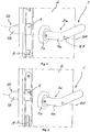
- FIGS. 1 and 2 show views of a door locking system 1 according to the invention.
- the door locking system 1 is mounted on a door 2 and comprises a first door handle unit 3a and a second door handle unit 3b.
- the first door handle unit 3a comprises a first door handle 4a and a first cover unit 5a which fixes the door handle 4a on the door 2 so as to be pivotable about an axis of rotation DA.
- the second door handle unit 3b comprises a second door handle 4b and a second cover unit 5b - shown in FIG Fig. 3-6 - Which fixes the door handle 4b on the door 2 so that it can pivot about the axis of rotation DA.
- the door locking system 1 further comprises a door lock 6 which can be opened by pivoting the door handles 4a and 4b about the axis of rotation DA.
- the door handle units 3a and 3b are coupled to one another via a coupling device 7 with a coupling pin 8.
- the coupling pin 8 is in a decoupling position and in Fig. 2 adjusted in a coupling position axially to the axis of rotation DA.
- the structure and the mode of operation of the door locking system 1 according to the invention are based on the following Fig. 3-11 explained in more detail.
- a lock system 9 which can be actuated independently of the door locking system 1 according to the invention and which is not part of the invention.
- FIGS. 3 to 6 show sectional views of the door locking system 1.
- the coupling device 7 connects the two door handles 4a and 4b axially to one another.
- the coupling device 7 has an axially aligned polygonal pin 10 which has a first pin piece 11 a and a second pin piece 11 b.
- the first pin piece 11a is connected to the first door handle 4a and the second pin piece 11b is connected to the second door handle 4b in a non-rotatable and axially positive manner.
- a pivoting of the respective door handle 4a or 4b causes a pivoting of the respective pin piece 11a or 11b.
- the two pin pieces 11 a and 11 b are separated from one another or are components that are independent of one another and are connected to one another via the coupling pin 8.
- the door lock 6 is coupled to the first pin piece 11a, so that the door lock 6 can only be opened when the first pin piece 11a is pivoted.
- the coupling pin 8 is adjusted to the coupling position.
- the two pin pieces 11a and 11b of the polygonal pin 10 are non-rotatably connected to one another and the two door handles 4a and 4b can be pivoted together about the axis of rotation DA.
- the door lock 6 can be opened by pivoting the first door handle 4a or by pivoting the second door handle 4b.
- the door locking system 1 acts like a conventional door locking system with a one-piece polygonal pin.
- the coupling pin 8 is adjusted into the decoupling position, for which purpose the coupling pin is axially displaced towards the second door handle 4b.
- the two pin pieces 11a and 11b of the polygonal pin 10 can be rotated relative to one another.
- the second door handle 4b and thereby the second pin piece 11b can be pivoted about the axis of rotation DA, but the first pin piece 11a and the first door handle 4a are not pivoted.
- the door lock 6 cannot be opened when the second door handle 4b is pivoted. If, however, the first door handle 4a is pivoted, the first pin piece 11a is also pivoted and the door lock 6 is opened as a result.
- the coupling pin 8 has a rotary area 12 and a non-rotationally symmetrical coupling area 13 and is arranged in the polygonal pin 10.
- a first mating contour 14a is formed in the first pin piece 11a and a second mating contour 14b for the coupling area is formed in the second pin piece 11b.
- the mating contours 14a and 14b are identical to one another and can accommodate the coupling area 13 of the coupling pin 8 in a form-fitting manner.
- the first pin piece 11a there is also a counter contour 15 of rotation formed, in which the rotary area 12 of the coupling pin 8 is received in a radially fixed, axially displaceable and rotatable manner.
- the coupling pin 8 is shown in the coupling position.
- the coupling pin 8 is axially displaced towards the first door handle 4a, so that the coupling area 13 is received in the first mating contour 14a and in the second mating contour 14b.
- the pin pieces 11a and 11b are connected to one another in a rotationally fixed manner due to the form fit between the coupling region 13 and the mating contours 14a and 14b.
- the coupling pin is in the decoupling position and axially moved towards the second door handle 4b.
- the coupling area 13 of the coupling pin 8 is only in positive engagement with the second mating contour 14b.
- the rotary area 13 of the coupling pin 8 is arranged in some areas in the mating contour 14a and cannot prevent the coupling pin 8 from rotating in the first pin piece 11a.
- the two pin pieces 11a and 11b can be rotated relative to one another.
- the coupling pin 8 is axially fixed in the coupling position and in the decoupling position on the second pin piece 11b by means of a latching unit 16.
- the structure and the mode of operation of the locking unit 16 are based on the following Fig. 7 explained in more detail.
- the latching unit prevents the coupling pin 8 from inadvertently moving from the decoupling position into the coupling position and vice versa.
- the coupling pin 8 can be adjusted manually from the coupling position into the decoupling position.
- the coupling pin 8 protrudes axially out of the first door handle 4a in the coupling position and can be adjusted towards the second door handle 4b into the decoupling position.
- a reset unit 17 is provided for adjusting the coupling pin 8 from the decoupling position into the coupling position.
- the resetting unit 17 comprises a radially aligned formation 18 on the coupling pin 8 and a ramp 19 formed transversely to the axis of rotation DA on the first pin piece 11a. Is the coupling pin 8 in the decoupling position and when the first door handle 4a is pivoted, the first pin piece 11a also pivots.
- the ramp 19 is rotated about the axis of rotation DA and shifts the formation 18 and thereby the coupling pin 8 towards the first door handle 4a.
- a helical spring 20 of the restoring unit 17 supports the axial movement of the coupling pin 8.
- the helical spring 20 In the decoupling position, the helical spring 20 is clamped between the ramp 19 and a circumferential stop edge 21 of the coupling pin 8 and the recess 18 rests against the ramp 19, as in FIG Fig. 6 is recognizable.
- the helical spring 20 is relaxed and the recess 18 is removed from the ramp 19, as in FIG Fig. 4 is recognizable.
- Fig. 7 shows an exploded view of the coupling device 7.
- the coupling pin 8 is held in the decoupling position and in the coupling position by means of the latching unit 16.
- the locking unit 16 comprises a radially resilient ball 22 and two axially adjacent and radially aligned openings 23 and 24.
- the ball 22 engages in the coupling position in the opening 23 and in the decoupling position in the opening 24, as in FIG Fig. 4 and Fig. 6 is recognizable.
- the openings 23 and 24 are formed in the coupling pin 8 and the ball 22 in this exemplary embodiment is fastened in a radially resilient manner to the second pin piece 11b of the polygonal pin 10 by means of a spring 27 and a screw 28.
- the coupling pin 8 is in several parts and comprises an axial stop 25, a coupling pin part 29, a stop nut 30 and an actuating screw 31.
- the axial stop 25 is formed facing the second pin piece 11b by means of a screw and a nut and is fixed on the coupling pin part 29.
- the stop nut 30, which forms the stop edge 21 for the helical spring 20 of the resetting unit 17, is screwed onto the coupling pin part 29, facing the first pin piece 11a.
- the actuating screw 31 with the stop nut 21 faces away from the coupling pin part 29 screwed.
- the actuating screw 31 protrudes from the first door handle 4a in some areas.
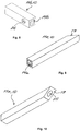
- Fig. 8 shows a view of the second pin piece 11b of the polygonal pin 10.
- a ball opening 26 can be seen, which is provided for fastening the latching unit 16 to the second pin piece 11b.
- Figures 9 and 10 show views of the first pin piece 11a of the polygonal pin 10.
- the second mating contour 14a and the rotating mating contour 15 can be seen here.
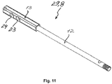
- Fig. 11 shows a view of one of the coupling pin part 29 of the coupling pin 8 of the coupling device 7.
- the door lock 6 can advantageously be opened in the coupling position of the coupling pin 8 by the two door handles 4a and 4b and in the decoupling position of the coupling pin 8 exclusively by the first door handle 4a.
- the door locking system 1 according to the invention is constructed in a compact and material-saving manner in comparison to conventional door locking systems.
Landscapes
- Engineering & Computer Science (AREA)
- Structural Engineering (AREA)
- Lock And Its Accessories (AREA)
Abstract
Description
- Die Erfindung betrifft ein Türschließsystem zum Öffnen und zum Schließen eines Türschlosses in einer Tür gemäß dem Oberbegriff des Anspruchs 1.
- Ein Türschließsystem umfasst üblicherweise eine erste Türgriffeinheit mit einem ersten Türgriff und eine zweite Türgriffeinheit mit einem zweiten Türgriff. Die Türgriffe sind dann beidseitig an der Tür angeordnet und über einen Vielkantstift miteinander drehfest verbunden. Dadurch können die Türgriffe gemeinsam an der Tür verschwenkt werden. Der Vielkantstift ist dann mit einem Türschloss wirksam verbunden, so dass beim Verschwenken eines der Türgriffe das geschlossene Türschloss geöffnet werden kann. Zusätzlich zum Türschließsystem kann auch ein Schließsystem an der Tür montiert sein. Das Schließsystem kann dabei unabhängig von dem Türschließsystem die Tür sperren oder freigeben. Eine Tür mit einem Türschließsystem und mit einem zusätzlichen Schließsystem ist beispielweise aus
EP 2 182 144 A1 bekannt. Derartige zusätzliche Schließsysteme sind üblicherweise unterhalb des Türschließsystems verbaut und beanspruchen demnach einen zusätzlichen Bauraum. - Die Aufgabe der Erfindung ist es daher, für ein Türschließsystem der gattungsgemäßen Art eine verbesserte oder zumindest alternative Ausführungsform anzugeben, bei der die beschriebenen Nachteile überwunden werden. Insbesondere soll das Türschließsystem kompakt ausgestaltet sein und ein Versperren des Türschlosses ermöglichen.
- Diese Aufgabe wird erfindungsgemäß durch den Gegenstand des unabhängigen Anspruchs 1 gelöst. Vorteilhafte Ausführungsformen sind Gegenstand der abhängigen Ansprüche.
- Ein Türschließsystem ist zum Öffnen und zum Schließen eines Türschlosses in einer Tür vorgesehen. Das Türschließsystem umfasst eine erste Türgriffeinheit mit einem ersten Türgriff und eine zweite Türgriffeinheit mit einem zweiten Türgriff. Der erste Türgriff und der zweite Türgriff sind dabei um eine gemeinsame Drehachse schwenkbar. Das Türschließsystem umfasst zudem eine Koppelvorrichtung mit einem axial ausgerichteten Vielkantstift, der ein erstes Stiftstück und ein zweites Stiftstück aufweist. Das erste Stiftstück ist dabei mit dem ersten Türgriff und das zweite Stiftstück ist mit dem zweiten Türgriff drehfest verbunden. Erfindungsgemäß sind die Stiftstücke des Vielkantstifts voneinander getrennt und ausschließlich das erste Stiftstück des Vielkantstifts ist mit dem Türschloss koppelbar. In einem eingebauten Zustand des Türschließsystems, also bei dem in die Tür mit einem Türschloss eingebauten Türschließsystem, ist das erste Stiftstück des Vielkantstifts mit dem Türschloss zu dessen Öffnungsbetätigung gekoppelt. Die Koppelvorrichtung umfasst zudem einen axial ausgerichteten Koppelstift, der in dem Vielkantstift angeordnet und axial in eine Kopplungsposition und in eine Entkopplungsposition verstellbar ist. Die Stiftstücke des Vielkantstifts sind dabei in der Kopplungsposition des Koppelstifts drehfest miteinander verbunden und in der Entkopplungsposition des Koppelstifts relativ zueinander verdrehbar.
- Ist der Koppelstift in der Kopplungsposition, so sind die Stiftstücke und dadurch auch die Türgriffe drehfest miteinander verbunden. Beim Verschwenken eines der beiden Türgriffe werden die beiden Stiftstücke des Vielkantstifts und der andere Türgriff um die gemeinsame Drehachse verschwenkt. Das Türschloss ist dabei mit dem ersten Stiftstück koppelbar und kann also beim Verschwenken eines der Türgriffe geöffnet werden. Ist der Koppelstift in der Entkopplungsposition, so sind die Stiftstücke und dadurch auch die Türgriffe relativ zueinander verdrehbar. Beim Verschwenken des zweiten Türgriffs wird ausschließlich das zweite Stiftstück verschwenkt, das erste Stiftstück und der erste Türgriff verschwenken sich dabei jedoch nicht. Da das Türschloss mit dem ersten Stiftstück koppelbar bzw. gekoppelt ist, kann beim Verschwenken des zweiten Türgriffs das Türschloss nicht geöffnet werden. Beim Verschwenken des ersten Türgriffs wird jedoch stets das erste Stiftstück des Vielkantstifts verschwenkt und dadurch das mit diesem koppelbare Türschloss geöffnet.
- Mit dem erfindungsgemäßen Türschließsystem kann das Türschloss vorteilhafterweise in der Kopplungsposition des Koppelstifts durch die beiden Türgriffe und in der Entkopplungsposition des Koppelstifts ausschließlich durch den ersten Türgriff geöffnet werden. Diese vorteilhafte Wirkung wird durch den Koppelstift erreicht, der in dem Vielkantstift angeordnet ist und dadurch keinen zusätzlichen Bauraum benötigt. Das erfindungsgemäße Türschließsystem ist dadurch im Vergleich zu einem herkömmlichen Türschließsystem mit einem zusätzlichen Schließsystem kompakter aufgebaut. Zweckgemäß sind der erste Türgriff bzw. die erste Türgriffeinheit zur innenraumseitigen Montage und der zweite Türgriff bzw. die zweite Türgriffeinheit zur außenraumseitigen Montage vorgesehen.
- Das erfindungsgemäße Türschließsystem kann zur Realisierung einer Privatfunktion eingesetzt werden. So kann eine Person, die in einem Raum - wie beispielweise in einem Waschraum oder in einer Toilette - Privatsphäre wünscht, die Entkopplungsposition einstellen. In der Entkopplungsposition kann dann die Tür zu diesem Raum mit dem außenraumseitigen zweiten Türgriff nicht geöffnet werden. Zusätzlich stellt das erfindungsgemäße Türschließsystem eine Notöffnungsfunktion bereit, da die eingeschlossene Person mit dem innenraumseitigen ersten Türgriff das Türschloss immer öffnen kann. Insbesondere kann dadurch die Gefahr reduziert werden, dass sich Kinder selbst einsperren.
- Bei einer vorteilhaften Weiterbildung des Türschließsystems ist vorgesehen, dass der Koppelstift aus dem ersten Türgriff axial nach außen herausragt und von außen manuell aus der Kopplungsposition in die Entkopplungsposition verstellbar ist. Dadurch kann der Koppelstift innenraumseitig in die Entkopplungsposition verstellt werden und dadurch die Stiftstücke drehbar miteinander verbunden bzw. voneinander entkoppelt werden. Ist der Koppelstift nun in die Entkopplungsposition verstellt, so kann das Türschloss durch den zweiten Türgriff bzw. außenraumseitig nicht mehr geöffnet werden. Der Koppelstift bleibt dabei in der Entkopplungsposition, bis er in die Kopplungsposition verstellt wird.
- Vorteilhafterweise kann die Koppelvorrichtung eine Rückstelleinheit umfassen. Die Rückstelleinheit kann dabei beim Verschwenken des ersten Türgriffs den Koppelstift aus der Entkopplungsposition in die Kopplungsposition verstellen. Ist also der Koppelstift in der Entkopplungsposition und wird der erste Türgriff verschwenkt, so geht der Koppelstift automatisch in die Kopplungsposition über. Dadurch kann das Verstellen des Koppelstifts aus der Entkopplungsposition in die Kopplungsposition vereinfacht werden. Ferner kann auch ein ungewolltes Versperren der Tür verhindert werden, da sobald eine Person beim Verlassen eines Raums den ersten innenraumseitigen Türgriff verschwenkt, geht der Koppelstift automatisch in die Kopplungsposition über und die Tür kann auch außenraumseitig geöffnet werden. Ist der Koppelstift in der Kopplungsposition und wird der erste Türgriff betätigt, so bleibt der Koppelstift weiterhin in der Kopplungsposition. Ein Verstellen des Koppelstifts aus der Kopplungsposition in die Entkopplungsposition kann - wie oben beschrieben - manuell erfolgen.
- Bei einer Weiterbildung der Rückstelleinheit kann vorgesehen sein, dass die Rückstelleinheit eine Ausformung und eine Rampe umfasst. Dabei kann die Ausformung an dem Koppelstift ausgebildet oder angeordnet sein und von diesem radial abstehen. Die Rampe kann quer zur Drehachse an dem ersten Stiftstück des Vielkantstifts zu dem ersten Türgriff zugewandt ausgebildet sein. Die Ausformung liegt dann in der Entkopplungsposition des Koppelstifts an der Rampe an und gleitet beim Verschwenken des ersten Türgriffs an der Rampe axial ab. Da beim Verschwenken des ersten Türgriffs das erste Stiftstück verschwenkt wird, verdreht sich auch die Rampe um die Drehachse und verschiebt die Ausformung axial aus ihrer Stellung. Dadurch wird auch der Koppelstift aus der Entkopplungsposition in die Kopplungsposition axial verschoben.
- Zusätzlich kann vorgesehen sein, dass die Rückstelleinheit eine Schraubenfeder umfasst. Die Schraubenfeder kann um den Koppelstift angeordnet sein und stützt sich dann axial einseitig an die Rampe und andersseitig an einen radial umlaufenden Anschlagrand des Koppelstifts ab. Die Schraubenfeder ist in der Entkopplungsposition des Koppelstifts axial eingespannt und unterstützt beim Verschwenken des ersten Türgriffs das axiale Verschieben des Koppelstifts aus der Entkopplungsposition in die Kopplungsposition.
- Bei einer vorteilhaften Weiterbildung des Türschließsystems ist vorgesehen, dass der Koppelstift einen Drehbereich und einen dazu axial benachbarten und rotationsunsymmetrischen Koppelbereich aufweist. Über den Drehbereich sind dann der Koppelstift und das erste Stiftstück drehbar miteinander verbindbar. Der Drehbereich des Koppelstifts kann beispielweise zylindrisch sein. Denkbar ist dabei, dass für den Drehbereich des Koppelstifts in dem ersten Stiftstück eine Drehgegenkontur gebildet ist. Der Drehbereich des Koppelstifts ist dann innerhalb der Drehgegenkontur des ersten Stiftstücks radial fest, axial verschiebbar und drehbar aufgenommen. In dem ersten Stiftstück ist zudem eine erste Gegenkontur und in dem zweiten Stiftstück ist eine zweite Gegenkontur für den Koppelbereich ausgebildet. Beim Eingreifen des Koppelbereichs in die jeweilige Gegenkontur können dann der Koppelstift und das jeweilige Stiftstück drehfest miteinander verbunden sein. Mit anderen Worten können die jeweilige Gegenkontur und der Koppelbereich eine drehfeste und formschlüssige Verbindung miteinander eingehen. Die Gegenkonturen in den beiden Stiftstücken können dabei zueinander identisch sein.
- Vorteilhafterweise kann in der Entkopplungsposition des Koppelstifts der Koppelbereich außerhalb der ersten Gegenkontur des ersten Stiftstücks angeordnet sein und dadurch können die Stiftstücke relativ zueinander verdrehbar sein. Der Drehbereich kann dabei in dem ersten Stiftstück angeordnet sein. In der Kopplungsposition des Koppelstifts kann dann der Koppelbereich bereichsweise in der ersten Gegenkontur des ersten Stiftstücks und bereichsweise in der zweiten Gegenkontur des zweiten Stiftstücks angeordnet sein und dadurch können die Stiftstücke miteinander drehfest verbunden sein. In der Kopplungsposition des Koppelstifts gehen die jeweiligen Gegenkonturen und der Koppelbereich des Koppelstifts eine drehfeste formschlüssige Verbindung ein, die ein gemeinsames Verschwenken der beiden Stiftstücke und auch der Türgriffe um die gemeinsame Drehachse ermöglicht. Der Drehbereich des Koppelstifts kann dabei vollständig in dem ersten Stiftstück angeordnet sein. Durch die Verbindung der ersten Gegenkontur des ersten Stiftsstücks mit dem Koppelbereich bleibt das erste Stiftstück mit dem zweiten Stiftstück dennoch drehfest verbunden.
- Bei einer vorteilhaften Weiterbildung des Türschließsystems ist vorgesehen, dass die Koppelvorrichtung eine Rasteinheit aufweist, die den Koppelstift in der Kopplungsposition und in der Entkopplungsposition axial fixiert. Dadurch kann verhindert werden, dass der Koppelstift ungewollt aus der Entkopplungsposition in die Kopplungsposition übergeht und umgekehrt.
- Vorteilhafterweise kann die Rasteinheit eine radial federnde Kugel und zwei axial zueinander benachbarte und radial ausgerichtete Öffnungen umfassen. Dabei ist die Kugel in der Kopplungsposition in die eine Öffnung und in der Entkopplungsposition in die andere Öffnung eingerastet. Die Öffnungen sind dann in dem Koppelstift ausgebildet und die Kugel ist an dem zweiten Stiftstück des Vielkantstifts oder an dem zweiten Türgriff und das zweite Stiftstück des Vielkantstifts durchdringend radial federnd festgelegt. Alternativ ist auch denkbar, dass die Öffnungen in dem Koppelstift ausgebildet sind und die Kugel an dem ersten Stiftstück des Vielkantstifts oder an dem ersten Türgriff und das erste Stiftstück des Vielkantstifts durchdringend radial federnd festgelegt ist. Alternativ ist auch denkbar, dass die Öffnungen in dem ersten oder in dem zweiten Stiftstück ausgebildet sind und die Kugel an dem Koppelstift radial federnd festgelegt ist.
- Bei einer vorteilhaften Ausgestaltung des Türschließsystems ist vorgesehen, dass das Türschließsystem das Türschloss umfasst. Das Türschloss ist dann mit dem ersten Stiftstück des Vielkantstifts gekoppelt. Das Türschloss kann dann in der Entkopplungsposition des Koppelstifts ausschließlich durch das Verschwenken des ersten Türgriffs und in der Kopplungsposition des Koppelstifts durch das Verschwenken des ersten Türgriffs oder durch das Verschwenken des zweiten Türgriffs geöffnet werden.
- Weitere wichtige Merkmale und Vorteile der Erfindung ergeben sich aus den Unteransprüchen, aus den Zeichnungen und aus der zugehörigen Figurenbeschreibung anhand der Zeichnungen.
- Es versteht sich, dass die vorstehend genannten und die nachstehend noch zu erläuternden Merkmale nicht nur in der jeweils angegebenen Kombination, sondern auch in anderen Kombinationen oder in Alleinstellung verwendbar sind, ohne den Rahmen der vorliegenden Erfindung zu verlassen.
- Bevorzugte Ausführungsbeispiele der Erfindung sind in den Zeichnungen dargestellt und werden in der nachfolgenden Beschreibung näher erläutert, wobei sich gleiche Bezugszeichen auf gleiche oder ähnliche oder funktional gleiche Komponenten beziehen.
-
- Fig. 1
- eine Ansicht eines erfindungsgemäßen Türschließsystems mit einem Koppelstift in einer Kopplungsposition;
- Fig. 2
- eine Ansicht des erfindungsgemäßen Türschließsystems mit dem Koppelstift in einer Entkopplungsposition;
- Fig. 3 und 4
- Schnittansichten des erfindungsgemäßen Türschließsystems mit dem Koppelstift in der Kopplungsposition;
- Fig. 5 und 6
- Schnittansichten des erfindungsgemäßen Türschließsystems mit dem Koppelstift in der Entkopplungsposition;
- Fig. 7
- eine Explosionsansicht einer Koppelvorrichtung in dem erfindungsgemäßen Türschließsystem;
- Fig. 8 bis 10
- Ansichten von Stiftstücken eines Vielkantstifts der Koppelvorrichtung des erfindungsgemäßen Türschließsystems;
- Fig. 11
- eine Ansicht eines Teils eines Koppelstifts der Koppelvorrichtung des erfindungsgemäßen Türschließsystems.
-
Fig. 1 und Fig. 2 zeigen Ansichten eines erfindungsgemäßen Türschließsystems 1. Das Türschließsystem 1 ist an einer Tür 2 montiert und umfasst eine erste Türgriffeinheit 3a und eine zweite Türgriffeinheit 3b. Die erste Türgriffeinheit 3a umfasst einen ersten Türgriff 4a und eine erste Abdeckeinheit 5a, die den Türgriff 4a um eine Drehachse DA schwenkbar an der Tür 2 festlegt. Die zweite Türgriffeinheit 3b umfasst einen zweiten Türgriff 4b und eine zweite Abdeckeinheit 5b - gezeigt inFig. 3-6 , - die den Türgriff 4b um die Drehachse DA schwenkbar an der Tür 2 festlegt. Das Türschließsystem 1 umfasst ferner ein Türschloss 6, der durch das Verschwenken der Türgriffe 4a und 4b um die Drehachse DA geöffnet werden kann. Die Türgriffeinheiten 3a und 3b sind über eine Koppelvorrichtung 7 mit einem Koppelstift 8 miteinander gekoppelt. InFig. 1 ist der Koppelstift 8 in eine Entkopplungsposition und inFig. 2 in eine Kopplungsposition axial zur Drehachse DA verstellt. Den Aufbau und die Wirkungsweise des erfindungsgemäßen Türschließsystems 1 werden im Folgenden anhandFig. 3-11 näher erläutert. Unterhalb des Türschließsystems 1 ist zudem ein Schlosssystem 9 angeordnet, das unabhängig von dem erfindungsgemäßen Türschließsystem 1 betätigbar ist und kein Teil der Erfindung ist. -
Fig. 3 bis Fig. 6 zeigen Schnittansichten des Türschließsystems 1. Wie hier erkennbar, verbindet die Koppelvorrichtung 7 die beiden Türgriffe 4a und 4b axial miteinander. Dazu weist die Koppelvorrichtung 7 einen axial ausgerichteten Vielkantstift 10 auf, der ein erstes Stiftstück 11 a und ein zweites Stiftstück 11b aufweist. Das erste Stiftstück 11a ist mit dem ersten Türgriff 4a und das zweite Stiftstück 11b ist mit dem zweiten Türgriff 4b jeweils formschlüssig drehfest und axial verbunden. Ein Verschwenken des jeweiligen Türgriffs 4a bzw. 4b bewirkt dabei ein Verschwenken des jeweiligen Stiftstücks 11a bzw. 11b. Die beiden Stiftstücke 11 a und 11b sind voneinander getrennt bzw. sind voneinander unabhängige Bauteile und sind über den Koppelstift 8 miteinander verbunden. Das Türschloss 6 ist dabei mit dem ersten Stiftstück 11a gekoppelt, so dass das Türschloss 6 nur beim Verschwenken des ersten Stiftstücks 11a geöffnet werden kann. - In
Fig. 3 und Fig. 4 ist der Koppelstift 8 in die Kopplungsposition verstellt. In der Kopplungsposition sind die beiden Stiftstücke 11 a und 11b des Vielkantstifts 10 drehfest miteinander verbunden und die beiden Türgriffe 4a und 4b können gemeinsam um die Drehachse DA verschwenkt werden. Das Türschloss 6 kann durch das Verschwenken des ersten Türgriffs 4a oder durch das Verschwenken des zweiten Türgriffs 4b geöffnet werden. Mit anderen Worten wirkt das Türschließsystem 1 in der Kopplungsposition des Koppelstifts 8 wie ein herkömmliches Türschließsystem mit einem einteiligen Vielkantstift. - In
Fig. 5 und Fig. 6 ist der Koppelstift 8 in die Entkopplungsposition verstellt, wozu der Koppelstift axial zu dem zweiten Türgriff 4b hin verschoben ist. In der Entkopplungsposition sind die beiden Stiftstücke 11a und 11b des Vielkantstifts 10 relativ zueinander verdrehbar. In der Entkopplungsposition des Koppelstifts 8 kann zwar der zweite Türgriff 4b und dadurch das zweite Stiftstück 11b um die Drehachse DA verschwenkt werden, das erste Stiftstück 11a und der erste Türgriff 4a werden jedoch nicht verschwenkt. Dadurch kann in der Entkopplungsposition des Koppelstifts 8 das Türschloss 6 beim Verschwenken des zweiten Türgriffs 4b nicht geöffnet werden. Wird jedoch das erste Türgriff 4a verschwenkt, so wird auch das erste Stiftsstück 11a verschwenkt und dadurch das Türschloss 6 geöffnet. - Wie in
Fig. 4 undFig. 6 gezeigt, weist der Koppelstift 8 einen Drehbereich 12 und einen nicht rotationssymmetrischen Koppelbereich 13 auf und ist in dem Vielkantstift 10 angeordnet. In dem ersten Stiftstück 11a ist dabei eine erste Gegenkontur 14a und in dem zweiten Stiftstück 11b ist eine zweite Gegenkontur 14b für den Koppelbereich ausgebildet. Die Gegenkonturen 14a und 14b sind zueinander identisch und können den Koppelbereich 13 des Koppelstifts 8 formschlüssig aufnehmen. In dem ersten Stiftstück 11a ist zudem eine Drehgegenkontur 15 ausgebildet, in der der Drehbereich 12 des Koppelstifts 8 radial fest, axial verschiebbar und drehbar aufgenommen ist. - In
Fig. 4 ist der Koppelstift 8 in der Kopplungsposition gezeigt. Hier ist der Koppelstift 8 axial zu dem ersten Türgriff 4a hin verschoben, so dass der Koppelbereich 13 in der ersten Gegenkontur 14a und in der zweiten Gegenkontur 14b aufgenommen ist. Durch den Formschluss zwischen dem Koppelbereich 13 und den Gegenkonturen 14a und 14b sind die Stiftstücke 11a und 11b drehfest miteinander verbunden. InFig. 6 ist der Koppelstift in der Entkopplungsposition und axial zu dem zweiten Türgriff 4b hin verschoben. Der Koppelbereich 13 des Koppelstifts 8 steht nur mit der zweiten Gegenkontur 14b formschlüssig im Eingriff. Der Drehbereich 13 des Koppelstifts 8 ist dabei bereichsweise in der Gegenkontur 14a angeordnet und kann das Verdrehen des Koppelstifts 8 in dem ersten Stiftstück 11a nicht verhindern. Die beiden Stiftstücke 11a und 11b sind relativ zueinander verdrehbar. Der Koppelstift 8 ist in der Kopplungsposition und in der Entkopplungsposition an dem zweiten Stiftstück 11b mittels einer Rasteinheit 16 axial festgelegt. Den Aufbau und die Wirkungsweise der Rasteinheit 16 werden im Folgenden anhandFig. 7 näher erläutert. Die Rasteinheit verhindert, dass der Koppelstift 8 ungewollt aus der Entkopplungsposition in die Kopplungsposition und umgekehrt übergeht. - Der Koppelstift 8 kann aus der Kopplungsposition in die Entkopplungsposition manuell verstellt werden. Dazu ragt der Koppelstift 8 in der Kopplungsposition aus dem ersten Türgriff 4a axial heraus und kann zu dem zweiten Türgriff 4b hin in die Entkopplungsposition verstellt werden. Zum Verstellen des Koppelstifts 8 aus der Entkopplungsposition in die Kopplungsposition ist eine Rückstelleinheit 17 vorgesehen. Die Rückstelleinheit 17 umfasst eine radial ausgerichtete Ausformung 18 an dem Koppelstift 8 und eine quer zur Drehachse DA ausgebildete Rampe 19 an dem ersten Stiftstück 11a. Ist das Koppelstift 8 in der Entkopplungsposition und wird das erste Türgriff 4a verschwenkt, so verschwenkt sich auch das erste Stiftstück 11a. Die Rampe 19 wird um die Drehachse DA verdreht und verschiebt die Ausformung 18 und dadurch den Koppelstift 8 zu dem ersten Türgriff 4a hin. Eine Schraubenfeder 20 der Rückstelleinheit 17 unterstützt dabei die axiale Bewegung des Koppelstifts 8. In der Entkopplungsposition ist die Schraubenfeder 20 zwischen der Rampe 19 und einem umlaufenden Anschlagrand 21 des Koppelstifts 8 eingespannt und die Ausformung 18 liegt an der Rampe 19 an, wie in
Fig. 6 erkennbar ist. In der Kopplungsposition ist die Schraubenfeder 20 entspannt und die Ausformung 18 ist von der Rampe 19 entfernt, wie inFig. 4 erkennbar ist. -
Fig. 7 zeigt eine Explosionsansicht der Koppelvorrichtung 7. Wie oben bereits beschrieben, wird der Koppelstift 8 in der Entkopplungsposition und in der Kopplungsposition mittels der Rasteinheit 16 gehalten. Die Rasteinheit 16 umfasst dabei eine radial federnde Kugel 22 und zwei axial zueinander benachbarte und radial ausgerichtete Öffnungen 23 und 24. Die Kugel 22 rastet dabei in der Kopplungsposition in die Öffnung 23 und in der Entkopplungsposition in die Öffnung 24 ein, wie inFig. 4 undFig. 6 erkennbar ist. Die Öffnungen 23 und 24 sind in dem Koppelstift 8 ausgebildet und die Kugel 22 ist in diesem Ausführungsbeispiel an dem zweiten Stiftstück 11b des Vielkantstifts 10 mittels einer Feder 27 und einer Schraube 28 radial federnd befestigt. Der Koppelstift 8 ist mehrteilig und umfasst einen axialen Anschlag 25, ein Koppelstiftteil 29, eine Anschlagmutter 30 und eine Betätigungsschraube 31. Der axiale Anschlag 25 ist dem zweiten Stiftstück 11b zugewandt mittels einer Schraube und einer Mutter gebildet und ist an dem Koppelstiftteil 29 festgelegt. Dem ersten Stiftstück 11a zugewandt ist an dem Koppelstiftteil 29 die Anschlagmutter 30 aufgeschraubt, die den Anschlagrand 21 für die Schraubenfeder 20 der Rückstelleinheit 17 bildet. Von dem Koppelstiftteil 29 abgewandt ist zudem die Betätigungsschraube 31 mit der Anschlagmutter 21 verschraubt. Die Betätigungsschraube 31 ragt bereichsweise aus dem ersten Türgriff 4a heraus. -
Fig. 8 zeigt eine Ansicht des zweiten Stiftstücks 11b des Vielkantstifts 10. Hier ist eine Kugelöffnung 26 zu sehen, die zum Befestigen der Rasteinheit 16 an dem zweiten Stiftstück 11b vorgesehen ist.Fig. 9 und Fig. 10 zeigen Ansichten des ersten Stiftstücks 11a des Vielkantstifts 10. Insbesondere sind hier die zweite Gegenkontur 14a und die Drehgegenkontur 15 erkennbar.Fig. 11 zeigt eine Ansicht eines des Koppelstiftsteils 29 des Koppelstiftes 8 der Koppelvorrichtung 7. - Mit dem erfindungsgemäßen Türschließsystem 1 kann das Türschloss 6 vorteilhafterweise in der Kopplungsposition des Koppelstifts 8 durch die beiden Türgriffe 4a und 4b und in der Entkopplungsposition des Koppelstifts 8 ausschließlich durch den ersten Türgriff 4a geöffnet werden. Das erfindungsgemäße Türschließsystem 1 ist im Vergleich zu herkömmlichen Türschließsystemen kompakt und materialsparend aufgebaut.
Claims (10)
- Türschließsystem (1) zum Öffnen und zum Schließen eines Türschlosses (6) in einer Tür (2),- wobei das Türschließsystem (1) eine erste Türgriffeinheit (3a) mit einem ersten Türgriff (4a) und eine zweite Türgriffeinheit (3b) mit einem zweiten Türgriff (4b) umfasst,- wobei der erste Türgriff (4a) und der zweite Türgriff (4b) um eine gemeinsame Drehachse (DA) schwenkbar sind,- wobei das Türschließsystem (1) eine Koppelvorrichtung (7) mit einem axial ausgerichteten Vielkantstift (10) umfasst, der ein erstes Stiftstück (11a) und ein zweites Stiftstück (11b) aufweist,- wobei das erste Stiftstück (11a) mit dem ersten Türgriff (4a) und das zweite Stiftstück (11b) mit dem zweiten Türgriff (4b) drehfest verbunden sind,dadurch gekennzeichnet,- dass die Stiftstücke (11a, 11b) des Vielkantstifts (10) voneinander getrennt sind und ausschließlich das erste Stiftstück (11a) des Vielkantstifts (10) mit dem Türschloss (6) koppelbar ist,- dass die Koppelvorrichtung (7) einen axial ausgerichteten Koppelstift (8) umfasst, der in dem Vielkantstift (10) angeordnet und axial in eine Kopplungsposition und in eine Entkopplungsposition verstellbar ist, und- dass die Stiftstücke (11a, 11b) des Vielkantstifts (10) in der Kopplungsposition des Koppelstifts (8) drehfest miteinander verbunden sind und in der Entkopplungsposition des Koppelstifts (8) relativ zueinander verdrehbar sind.
- Türschließsystem nach Anspruch 1,
dadurch gekennzeichnet,
dass der Koppelstift (8) aus dem ersten Türgriff (4a) axial nach außen herausragt und von außen manuell aus der Kopplungsposition in die Entkopplungsposition verstellbar ist. - Türschließsystem nach Anspruch 1 oder 2,
dadurch gekennzeichnet,
dass die Koppelvorrichtung (7) eine Rückstelleinheit (17) umfasst, die beim Verschwenken des ersten Türgriffs (4a) den Koppelstift (8) aus der Entkopplungsposition in die Kopplungsposition verstellt. - Türschließsystem nach Anspruch 3,
dadurch gekennzeichnet,- dass die Rückstelleinheit (17) eine Ausformung (18) und eine Rampe (19) umfasst, wobei die Ausformung (18) an dem Koppelstift (8) angeordnet ist und von diesem radial absteht und die Rampe (19) quer zur Drehachse (DA) an dem ersten Stiftstück (11a) des Vielkantstifts (10) zu dem ersten Türgriff (4a) zugewandt ausgebildet ist, und- dass die Ausformung (18) in der Entkopplungsposition des Koppelstifts (8) an der Rampe (19) anliegt und beim Verschwenken des ersten Türgriffs (4a) an der Rampe (19) axial abgleitet und dadurch der Koppelstift (8) aus der Entkopplungsposition in die Kopplungsposition verstellt wird. - Türschließsystem nach Anspruch 4,
dadurch gekennzeichnet,- dass die Rückstelleinheit (17) eine Schraubenfeder (20) umfasst, die um den Koppelstift (8) angeordnet ist und sich axial einseitig an die Rampe (19) und andersseitig an einen radial umlaufenden Anschlagrand (21) des Koppelstifts (8) abstützt, und- dass die Schraubenfeder (20) in der Entkopplungsposition des Koppelstifts axial eingespannt ist und beim Verschwenken des ersten Türgriffs (4a) das axiale Verschieben des Koppelstifts (8) aus der Entkopplungsposition in die Kopplungsposition unterstützt. - Türschließsystem nach einem der Ansprüche 1 bis 5,
dadurch gekennzeichnet,- dass der Koppelstift (8) einen Drehbereich (12) und einen dazu axial benachbarten und rotationsunsymmetrischen Koppelbereich (13) aufweist, und- dass über den Drehbereich (12) der Koppelstift (8) und das erste Stiftstück (11a) drehbar miteinander verbindbar sind, und- dass in dem ersten Stiftstück (11a) eine erste Gegenkontur (14a) und in dem zweiten Stiftstück eine zweite Gegenkontur (14b) für den Koppelbereich (13) ausgebildet sind, so dass beim Eingreifen des Koppelbereichs (13) in die jeweilige Gegenkontur (14a, 14b) der Koppelstift (8) und das jeweilige Stiftstück (11a, 11b) drehfest miteinander verbindbar sind. - Türschließsystem nach Anspruch 6,
dadurch gekennzeichnet,- dass in der Entkopplungsposition des Koppelstifts (8) der Koppelbereich (13) außerhalb der ersten Gegenkontur (14a) des ersten Stiftstücks (11a) angeordnet ist und dadurch die Stiftstücke (11a, 11b) relativ zueinander verdrehbar sind, und- dass in der Kopplungsposition des Koppelstifts (8) der Koppelbereich (13) bereichsweise in der ersten Gegenkontur (14a) des ersten Stiftstücks (11a) und bereichsweise in der zweiten Gegenkontur (14b) des zweiten Stiftstück (11b) angeordnet ist und dadurch die Stiftstücke (11a, 11b) miteinander drehfest verbunden sind. - Türschließsystem nach einem der Ansprüche 1 bis 7,
dadurch gekennzeichnet,
dass die Koppelvorrichtung (7) eine Rasteinheit (16) aufweist, die den Koppelstift (8) in der Kopplungsposition und in der Entkopplungsposition axial fixiert. - Türschließsystem nach Anspruch 8,
dadurch gekennzeichnet,- dass die Rasteinheit (16) eine radial federnde Kugel (22) und zwei axial zueinander benachbarte und radial ausgerichtete Öffnungen (23, 24) umfasst, wobei die Kugel (22) in der Kopplungsposition in die eine Öffnung (23) und in der Entkopplungsposition in die andere Öffnung (24) eingerastet ist, und- dass die Öffnungen (23, 24) in dem Koppelstift (8) ausgebildet sind und die Kugel (22) an dem zweiten Stiftstück (11b) des Vielkantstifts (10) oder an dem zweiten Türgriff (4b) und das zweite Stiftstück (11b) des Vielkantstifts (10) durchdringend radial federnd festgelegt ist. - Türschließsystem nach einem der Ansprüche 1 bis 9,
dadurch gekennzeichnet,- dass das Türschließsystem (1) das Türschloss (6) umfasst, das mit dem ersten Stiftstück (11a) des Vielkantstifts (10) gekoppelt ist, und- dass das Türschloss (6) in der Entkopplungsposition des Koppelstifts (8) ausschließlich durch das Verschwenken des ersten Türgriffs (4a) und in der Kopplungsposition des Koppelstifts (8) durch das Verschwenken des ersten Türgriffs (4a) oder durch das Verschwenken des zweiten Türgriffs (4b) geöffnet werden kann.
Applications Claiming Priority (1)
| Application Number | Priority Date | Filing Date | Title |
|---|---|---|---|
| DE102020201152.4A DE102020201152A1 (de) | 2020-01-30 | 2020-01-30 | Türschließsystem |
Publications (3)
| Publication Number | Publication Date |
|---|---|
| EP3859102A1 true EP3859102A1 (de) | 2021-08-04 |
| EP3859102B1 EP3859102B1 (de) | 2023-09-27 |
| EP3859102C0 EP3859102C0 (de) | 2023-09-27 |
Family
ID=74175707
Family Applications (1)
| Application Number | Title | Priority Date | Filing Date |
|---|---|---|---|
| EP21151279.3A Active EP3859102B1 (de) | 2020-01-30 | 2021-01-13 | Türschliesssystem |
Country Status (4)
| Country | Link |
|---|---|
| US (1) | US20210238882A1 (de) |
| EP (1) | EP3859102B1 (de) |
| DE (1) | DE102020201152A1 (de) |
| PL (1) | PL3859102T3 (de) |
Cited By (2)
| Publication number | Priority date | Publication date | Assignee | Title |
|---|---|---|---|---|
| EP4124706A1 (de) * | 2021-07-29 | 2023-02-01 | Karcher GmbH | Türschliesssystem |
| GB2606214B (en) * | 2021-04-29 | 2024-10-02 | Kingsway Enterprises Uk Ltd | Lock |
Families Citing this family (6)
| Publication number | Priority date | Publication date | Assignee | Title |
|---|---|---|---|---|
| US11313149B2 (en) * | 2017-01-20 | 2022-04-26 | Sam Morrison | Systems, devices, and/or methods for managing door locks |
| USD965410S1 (en) * | 2021-07-09 | 2022-10-04 | Jiangmen Pengjiang MTT Gloria Trading Co., Ltd. | Fingerprint lock |
| DE202022103552U1 (de) | 2022-06-27 | 2022-07-19 | C & F Köhn Design GmbH & Co.KG | Türschließsystem |
| PL4438836T3 (pl) * | 2023-03-27 | 2026-04-20 | Hermat-Metallwaren B. Porst GmbH | Układ zamykający oraz drzwi lub okno z takim układem zamykającym |
| DE202023102812U1 (de) | 2023-05-22 | 2023-06-26 | C & F Köhn Design GmbH & Co.KG | Türschließsystem |
| CN221096120U (zh) * | 2023-10-24 | 2024-06-07 | 江门市蓬江区惠华建筑五金有限公司 | 配合门锁使用的门配件 |
Citations (6)
| Publication number | Priority date | Publication date | Assignee | Title |
|---|---|---|---|---|
| US1387888A (en) * | 1920-10-26 | 1921-08-16 | Annon W Holt | Door-latch |
| DE369871C (de) * | 1921-09-04 | 1923-02-24 | Franz Kubin | Riegelfallenschloss mit unter Ausschaltung des aeusseren Drueckers feststellbarer Falle |
| US2469601A (en) * | 1945-07-02 | 1949-05-10 | Gustav A Lee | Door latch |
| DE3844281A1 (de) * | 1988-12-30 | 1989-06-01 | Rupert Meyr | Tuerverriegelungsvorrichtung zum einseitigen verschliessen von tueren aller art |
| WO1997004203A1 (de) * | 1995-07-19 | 1997-02-06 | Hartmut Trilk | Umschaltvorrichtung für einen tür- oder fensterbeschlag |
| EP2182144A1 (de) | 2008-10-31 | 2010-05-05 | ALMAR s.p.a. | Tür- oder Fensterbeschlag |
Family Cites Families (7)
| Publication number | Priority date | Publication date | Assignee | Title |
|---|---|---|---|---|
| US3024055A (en) * | 1958-03-22 | 1962-03-06 | Novarino Giacomo Cipriano | Lock for doors, with a handle disengageable from the control member |
| JPS50108890U (de) | 1974-02-20 | 1975-09-05 | ||
| US5816086A (en) * | 1996-08-15 | 1998-10-06 | Schlage Lock Company | Axial moving pushbutton for a lock having rotary locking and release motions |
| GB2332470A (en) * | 1997-11-12 | 1999-06-23 | R G Trade Supplies And Enginee | Latch member restraint |
| US6802194B1 (en) | 2003-10-16 | 2004-10-12 | Shen Mu-Lin | Clutch mechanism for a lock |
| DE202013004101U1 (de) * | 2013-05-03 | 2013-06-26 | Volker Grittner | Schubriegelverschluß zur Schubkasten- und Möbelverriegelung |
| US11035149B2 (en) * | 2017-11-03 | 2021-06-15 | Schlage Lock Company Llc | Modular cylindrical lockset |
-
2020
- 2020-01-30 DE DE102020201152.4A patent/DE102020201152A1/de active Pending
-
2021
- 2021-01-13 EP EP21151279.3A patent/EP3859102B1/de active Active
- 2021-01-13 PL PL21151279.3T patent/PL3859102T3/pl unknown
- 2021-01-26 US US17/158,532 patent/US20210238882A1/en not_active Abandoned
Patent Citations (6)
| Publication number | Priority date | Publication date | Assignee | Title |
|---|---|---|---|---|
| US1387888A (en) * | 1920-10-26 | 1921-08-16 | Annon W Holt | Door-latch |
| DE369871C (de) * | 1921-09-04 | 1923-02-24 | Franz Kubin | Riegelfallenschloss mit unter Ausschaltung des aeusseren Drueckers feststellbarer Falle |
| US2469601A (en) * | 1945-07-02 | 1949-05-10 | Gustav A Lee | Door latch |
| DE3844281A1 (de) * | 1988-12-30 | 1989-06-01 | Rupert Meyr | Tuerverriegelungsvorrichtung zum einseitigen verschliessen von tueren aller art |
| WO1997004203A1 (de) * | 1995-07-19 | 1997-02-06 | Hartmut Trilk | Umschaltvorrichtung für einen tür- oder fensterbeschlag |
| EP2182144A1 (de) | 2008-10-31 | 2010-05-05 | ALMAR s.p.a. | Tür- oder Fensterbeschlag |
Cited By (2)
| Publication number | Priority date | Publication date | Assignee | Title |
|---|---|---|---|---|
| GB2606214B (en) * | 2021-04-29 | 2024-10-02 | Kingsway Enterprises Uk Ltd | Lock |
| EP4124706A1 (de) * | 2021-07-29 | 2023-02-01 | Karcher GmbH | Türschliesssystem |
Also Published As
| Publication number | Publication date |
|---|---|
| DE102020201152A1 (de) | 2021-08-05 |
| US20210238882A1 (en) | 2021-08-05 |
| EP3859102B1 (de) | 2023-09-27 |
| PL3859102T3 (pl) | 2024-03-04 |
| EP3859102C0 (de) | 2023-09-27 |
Similar Documents
| Publication | Publication Date | Title |
|---|---|---|
| EP3859102B1 (de) | Türschliesssystem | |
| DE19823188C2 (de) | Kraftfahrzeugtürverschluß | |
| EP3784855B1 (de) | Kraftfahrzeugschloss | |
| EP4124706B1 (de) | Türschliesssystem | |
| EP3258036B1 (de) | Beschlag mit einer beschlagsicherung | |
| DE102013112570A1 (de) | Vorrichtung zum Betätigen eines in einem Schaltschrank befindlichen Schaltgeräts | |
| EP4159957B1 (de) | Türschliesssystem | |
| EP3498941B1 (de) | Betätigungshandhabe mit sperrvorrichtung | |
| DE102015108675A1 (de) | Zylinderschlossanordnung | |
| EP2050704A1 (de) | Notentriegelung | |
| EP3450659B1 (de) | Verschlussvorrichtung | |
| WO2020249165A1 (de) | Hebelanordnung für kraftfahrzeugtechnische anwendungen | |
| DE69611147T2 (de) | Schloss vom Typ eines entkuppelbaren Rotors | |
| DE102019200115B4 (de) | Türschließsystem | |
| DE69320077T2 (de) | Kraftfahrzeug-Türschloss mit einer Vorrichtung, zur Verhinderung jeglicher Betätigung des Sicherheitshebels | |
| DE102024122121B3 (de) | Endbeschlagstraffer | |
| DE102014115489B4 (de) | Kraftfahrzeugtürverschluss | |
| EP2788568B1 (de) | Aussenverriegelungsmodul für ein schloss | |
| EP2251517B1 (de) | Halteelement | |
| EP1163863A1 (de) | Karussellvorrichtung für einen Eckschrank | |
| WO2025046483A1 (de) | Türbeschlageinheit und zugehöriger türbeschlag | |
| DE1201146B (de) | Ventil, Hahn oder dergleichen Absperrorgan | |
| DE102018201186A1 (de) | Türschließsystem | |
| DE102020204648A1 (de) | Türschließsystem | |
| DE102022122496A1 (de) | Kraftfahrzeug-Schloss |
Legal Events
| Date | Code | Title | Description |
|---|---|---|---|
| PUAI | Public reference made under article 153(3) epc to a published international application that has entered the european phase |
Free format text: ORIGINAL CODE: 0009012 |
|
| STAA | Information on the status of an ep patent application or granted ep patent |
Free format text: STATUS: THE APPLICATION HAS BEEN PUBLISHED |
|
| AK | Designated contracting states |
Kind code of ref document: A1 Designated state(s): AL AT BE BG CH CY CZ DE DK EE ES FI FR GB GR HR HU IE IS IT LI LT LU LV MC MK MT NL NO PL PT RO RS SE SI SK SM TR |
|
| STAA | Information on the status of an ep patent application or granted ep patent |
Free format text: STATUS: REQUEST FOR EXAMINATION WAS MADE |
|
| 17P | Request for examination filed |
Effective date: 20211208 |
|
| RBV | Designated contracting states (corrected) |
Designated state(s): AL AT BE BG CH CY CZ DE DK EE ES FI FR GB GR HR HU IE IS IT LI LT LU LV MC MK MT NL NO PL PT RO RS SE SI SK SM TR |
|
| GRAP | Despatch of communication of intention to grant a patent |
Free format text: ORIGINAL CODE: EPIDOSNIGR1 |
|
| STAA | Information on the status of an ep patent application or granted ep patent |
Free format text: STATUS: GRANT OF PATENT IS INTENDED |
|
| RIC1 | Information provided on ipc code assigned before grant |
Ipc: E05B 63/00 20060101ALI20230501BHEP Ipc: E05B 65/00 20060101ALI20230501BHEP Ipc: E05B 13/10 20060101ALI20230501BHEP Ipc: E05B 63/16 20060101ALI20230501BHEP Ipc: E05B 15/00 20060101AFI20230501BHEP |
|
| INTG | Intention to grant announced |
Effective date: 20230601 |
|
| GRAS | Grant fee paid |
Free format text: ORIGINAL CODE: EPIDOSNIGR3 |
|
| GRAA | (expected) grant |
Free format text: ORIGINAL CODE: 0009210 |
|
| STAA | Information on the status of an ep patent application or granted ep patent |
Free format text: STATUS: THE PATENT HAS BEEN GRANTED |
|
| AK | Designated contracting states |
Kind code of ref document: B1 Designated state(s): AL AT BE BG CH CY CZ DE DK EE ES FI FR GB GR HR HU IE IS IT LI LT LU LV MC MK MT NL NO PL PT RO RS SE SI SK SM TR |
|
| REG | Reference to a national code |
Ref country code: GB Ref legal event code: FG4D Free format text: NOT ENGLISH |
|
| REG | Reference to a national code |
Ref country code: CH Ref legal event code: EP |
|
| REG | Reference to a national code |
Ref country code: DE Ref legal event code: R096 Ref document number: 502021001532 Country of ref document: DE |
|
| REG | Reference to a national code |
Ref country code: IE Ref legal event code: FG4D Free format text: LANGUAGE OF EP DOCUMENT: GERMAN |
|
| U01 | Request for unitary effect filed |
Effective date: 20231026 |
|
| U07 | Unitary effect registered |
Designated state(s): AT BE BG DE DK EE FI FR IT LT LU LV MT NL PT SE SI Effective date: 20231102 |
|
| PG25 | Lapsed in a contracting state [announced via postgrant information from national office to epo] |
Ref country code: GR Free format text: LAPSE BECAUSE OF FAILURE TO SUBMIT A TRANSLATION OF THE DESCRIPTION OR TO PAY THE FEE WITHIN THE PRESCRIBED TIME-LIMIT Effective date: 20231228 |
|
| PG25 | Lapsed in a contracting state [announced via postgrant information from national office to epo] |
Ref country code: RS Free format text: LAPSE BECAUSE OF FAILURE TO SUBMIT A TRANSLATION OF THE DESCRIPTION OR TO PAY THE FEE WITHIN THE PRESCRIBED TIME-LIMIT Effective date: 20230927 Ref country code: NO Free format text: LAPSE BECAUSE OF FAILURE TO SUBMIT A TRANSLATION OF THE DESCRIPTION OR TO PAY THE FEE WITHIN THE PRESCRIBED TIME-LIMIT Effective date: 20231227 Ref country code: HR Free format text: LAPSE BECAUSE OF FAILURE TO SUBMIT A TRANSLATION OF THE DESCRIPTION OR TO PAY THE FEE WITHIN THE PRESCRIBED TIME-LIMIT Effective date: 20230927 Ref country code: GR Free format text: LAPSE BECAUSE OF FAILURE TO SUBMIT A TRANSLATION OF THE DESCRIPTION OR TO PAY THE FEE WITHIN THE PRESCRIBED TIME-LIMIT Effective date: 20231228 |
|
| U20 | Renewal fee for the european patent with unitary effect paid |
Year of fee payment: 4 Effective date: 20240131 |
|
| PG25 | Lapsed in a contracting state [announced via postgrant information from national office to epo] |
Ref country code: IS Free format text: LAPSE BECAUSE OF FAILURE TO SUBMIT A TRANSLATION OF THE DESCRIPTION OR TO PAY THE FEE WITHIN THE PRESCRIBED TIME-LIMIT Effective date: 20240127 |
|
| PG25 | Lapsed in a contracting state [announced via postgrant information from national office to epo] |
Ref country code: ES Free format text: LAPSE BECAUSE OF FAILURE TO SUBMIT A TRANSLATION OF THE DESCRIPTION OR TO PAY THE FEE WITHIN THE PRESCRIBED TIME-LIMIT Effective date: 20230927 |
|
| PG25 | Lapsed in a contracting state [announced via postgrant information from national office to epo] |
Ref country code: SM Free format text: LAPSE BECAUSE OF FAILURE TO SUBMIT A TRANSLATION OF THE DESCRIPTION OR TO PAY THE FEE WITHIN THE PRESCRIBED TIME-LIMIT Effective date: 20230927 Ref country code: RO Free format text: LAPSE BECAUSE OF FAILURE TO SUBMIT A TRANSLATION OF THE DESCRIPTION OR TO PAY THE FEE WITHIN THE PRESCRIBED TIME-LIMIT Effective date: 20230927 Ref country code: IS Free format text: LAPSE BECAUSE OF FAILURE TO SUBMIT A TRANSLATION OF THE DESCRIPTION OR TO PAY THE FEE WITHIN THE PRESCRIBED TIME-LIMIT Effective date: 20240127 Ref country code: ES Free format text: LAPSE BECAUSE OF FAILURE TO SUBMIT A TRANSLATION OF THE DESCRIPTION OR TO PAY THE FEE WITHIN THE PRESCRIBED TIME-LIMIT Effective date: 20230927 Ref country code: CZ Free format text: LAPSE BECAUSE OF FAILURE TO SUBMIT A TRANSLATION OF THE DESCRIPTION OR TO PAY THE FEE WITHIN THE PRESCRIBED TIME-LIMIT Effective date: 20230927 Ref country code: SK Free format text: LAPSE BECAUSE OF FAILURE TO SUBMIT A TRANSLATION OF THE DESCRIPTION OR TO PAY THE FEE WITHIN THE PRESCRIBED TIME-LIMIT Effective date: 20230927 |
|
| REG | Reference to a national code |
Ref country code: DE Ref legal event code: R097 Ref document number: 502021001532 Country of ref document: DE |
|
| PLBE | No opposition filed within time limit |
Free format text: ORIGINAL CODE: 0009261 |
|
| STAA | Information on the status of an ep patent application or granted ep patent |
Free format text: STATUS: NO OPPOSITION FILED WITHIN TIME LIMIT |
|
| PG25 | Lapsed in a contracting state [announced via postgrant information from national office to epo] |
Ref country code: MC Free format text: LAPSE BECAUSE OF FAILURE TO SUBMIT A TRANSLATION OF THE DESCRIPTION OR TO PAY THE FEE WITHIN THE PRESCRIBED TIME-LIMIT Effective date: 20230927 |
|
| PG25 | Lapsed in a contracting state [announced via postgrant information from national office to epo] |
Ref country code: MC Free format text: LAPSE BECAUSE OF FAILURE TO SUBMIT A TRANSLATION OF THE DESCRIPTION OR TO PAY THE FEE WITHIN THE PRESCRIBED TIME-LIMIT Effective date: 20230927 |
|
| REG | Reference to a national code |
Ref country code: CH Ref legal event code: PL |
|
| 26N | No opposition filed |
Effective date: 20240628 |
|
| U20 | Renewal fee for the european patent with unitary effect paid |
Year of fee payment: 5 Effective date: 20250127 |
|
| PGFP | Annual fee paid to national office [announced via postgrant information from national office to epo] |
Ref country code: IE Payment date: 20250128 Year of fee payment: 5 |
|
| PGFP | Annual fee paid to national office [announced via postgrant information from national office to epo] |
Ref country code: CH Payment date: 20250201 Year of fee payment: 5 |
|
| PG25 | Lapsed in a contracting state [announced via postgrant information from national office to epo] |
Ref country code: CY Free format text: LAPSE BECAUSE OF FAILURE TO SUBMIT A TRANSLATION OF THE DESCRIPTION OR TO PAY THE FEE WITHIN THE PRESCRIBED TIME-LIMIT; INVALID AB INITIO Effective date: 20210113 |
|
| PG25 | Lapsed in a contracting state [announced via postgrant information from national office to epo] |
Ref country code: HU Free format text: LAPSE BECAUSE OF FAILURE TO SUBMIT A TRANSLATION OF THE DESCRIPTION OR TO PAY THE FEE WITHIN THE PRESCRIBED TIME-LIMIT; INVALID AB INITIO Effective date: 20210113 |
|
| GBPC | Gb: european patent ceased through non-payment of renewal fee |
Effective date: 20250113 |
|
| PG25 | Lapsed in a contracting state [announced via postgrant information from national office to epo] |
Ref country code: GB Free format text: LAPSE BECAUSE OF NON-PAYMENT OF DUE FEES Effective date: 20250113 |
|
| PG25 | Lapsed in a contracting state [announced via postgrant information from national office to epo] |
Ref country code: TR Free format text: LAPSE BECAUSE OF FAILURE TO SUBMIT A TRANSLATION OF THE DESCRIPTION OR TO PAY THE FEE WITHIN THE PRESCRIBED TIME-LIMIT Effective date: 20230927 |
|
| PGFP | Annual fee paid to national office [announced via postgrant information from national office to epo] |
Ref country code: PL Payment date: 20251217 Year of fee payment: 6 |
|
| REG | Reference to a national code |
Ref country code: CH Ref legal event code: U11 Free format text: ST27 STATUS EVENT CODE: U-0-0-U10-U11 (AS PROVIDED BY THE NATIONAL OFFICE) Effective date: 20260201 |
|
| U20 | Renewal fee for the european patent with unitary effect paid |
Year of fee payment: 6 Effective date: 20251230 |