EP4159957B1 - Türschliesssystem - Google Patents
Türschliesssystem Download PDFInfo
- Publication number
- EP4159957B1 EP4159957B1 EP22191915.2A EP22191915A EP4159957B1 EP 4159957 B1 EP4159957 B1 EP 4159957B1 EP 22191915 A EP22191915 A EP 22191915A EP 4159957 B1 EP4159957 B1 EP 4159957B1
- Authority
- EP
- European Patent Office
- Prior art keywords
- door
- door handle
- mounting plate
- handle
- axially
- Prior art date
- Legal status (The legal status is an assumption and is not a legal conclusion. Google has not performed a legal analysis and makes no representation as to the accuracy of the status listed.)
- Active
Links
Images


Classifications
-
- E—FIXED CONSTRUCTIONS
- E05—LOCKS; KEYS; WINDOW OR DOOR FITTINGS; SAFES
- E05B—LOCKS; ACCESSORIES THEREFOR; HANDCUFFS
- E05B3/00—Fastening knobs or handles to lock or latch parts
- E05B3/06—Fastening knobs or handles to lock or latch parts by means arranged in or on the rose or escutcheon
-
- E—FIXED CONSTRUCTIONS
- E05—LOCKS; KEYS; WINDOW OR DOOR FITTINGS; SAFES
- E05B—LOCKS; ACCESSORIES THEREFOR; HANDCUFFS
- E05B3/00—Fastening knobs or handles to lock or latch parts
- E05B3/06—Fastening knobs or handles to lock or latch parts by means arranged in or on the rose or escutcheon
- E05B3/065—Fastening knobs or handles to lock or latch parts by means arranged in or on the rose or escutcheon with spring biasing means for moving the handle over a substantial distance, e.g. to its horizontal position
Definitions
- the invention relates to a door locking system for opening and closing a door according to the preamble of claim 1.
- a door locking system usually comprises a first door handle unit with a first door handle and a second door handle unit with a second door handle.
- the door locking system usually has two mounting plates that are screwed together through the door.
- the door handles are firmly connected to one another by means of a polygonal pin and are arranged so that they can pivot on the mounting plates.
- the door locking system comprises two cover caps that cover the mounting plates on the outside and are firmly connected to the mounting plates.
- the disadvantage of a conventional door locking system is that the cover caps can be easily removed from the mounting plate. This can provide access to the interior of the door locking system and damage the door locking system and/or remove the cover cap and/or damage/scratch the door handle with the cover cap removed.
- the problem described can be particularly relevant in a publicly accessible building - such as a school.
- EP 2 840 203 A1 discloses a door locking system and a door handle unit with a door handle and a cover cap.
- the cover cap is in two parts and has a part attached to the door handle and a detachable cover ring.
- DE 10 2019 200 115 A1 discloses a door locking system with a door handle unit and a cover cap.
- the cover cap is connected to a mounting plate in a rotationally fixed manner via a unit that can be reached from the outside, so that the cover cap on the door handle can be rotated when the unit is operated.
- a door locking system reveals a door handle unit, a door handle and a cover cap.
- the cover cap on the door handle can be freely rotated.
- KR 2004 0059933 A discloses a door locking system and a door handle unit with a door handle and a cover cap.
- the door handle is connected to the cover cap and a mounting plate via two sleeves that can be screwed together.
- the door handle and the sleeve can be axially released together and separately from the cover cap.
- EP 2 182 144 A1 discloses a door locking system and a door handle unit comprising a door handle and a cover cap.
- the cover cap is rotatably connected to the door handle via a handle carrier plate. This allows the cover cap to be freely rotated on the door handle.
- DE 10 2018 201 186 A1 discloses a door locking system and a door handle unit comprising a door handle and a cover cap.
- the cover cap is in two parts and comprises a part attached to the door handle and a cover ring.
- the object of the invention is therefore to provide an improved or at least alternative embodiment for a door locking system of the generic type, in which the described disadvantages are overcome.
- a door locking system for opening and closing a door.
- the door locking system has a first door handle unit with a first door handle that can be pivoted about a pivot axis and with a cover cap that is aligned transversely to the pivot axis.
- the door locking system also has a second door handle unit that is identical to the first door handle unit or different from the first door handle unit and has a second door handle.
- the door locking system also has a first mounting plate that is aligned transversely to the pivot axis and a second mounting plate that is aligned transversely to the pivot axis. The first mounting plate and the second mounting plate are connected to one another in an axially fixed and rotationally fixed manner.
- the first door handle unit is axially fixed to the first mounting plate and the second door handle unit is axially fixed to the second door handle unit.
- the cover cap is axially fixed to the first mounting plate and axially fixed and rotatably connected to the first door handle. The cover cap can only be axially detached from the first mounting plate together with the entire first door handle unit.
- the cover cap has a thread running around the pivot axis and the first mounting plate has a counter-thread running around the pivot axis.
- the cover cap and the first mounting plate are then screwed together.
- the screw connection can only be established and released if the axially fixed arrangement of the first door handle unit on the first mounting plate - for example by an axially fixed connection of the door handles with the polygonal pin - is not established. After this, the cover cap can no longer be unscrewed from the first mounting plate.
- the screw connection additionally stabilizes the axially fixed connection between the first door handle unit and the first mounting plate.
- the cover cap is made in one piece and is pot-shaped.
- the cover cap then covers the mounting plate on a side facing the first door handle and aligned transversely to the pivot axis and on a side surrounding the pivot axis to the outside.
- the one-piece cover cap leaves no gaps through which access to the interior of the door locking system could be gained. This can also improve the external appearance of the door locking system.
- axial and radial always refer to the pivot axis of the first door handle and/or the second door handle.
- the cover cap can be directly connected to the first mounting plate in an axially fixed manner. In other words, there can be direct contact between the cover cap and the first mounting plate, or the cover cap and the first mounting plate can be in axially fixed engagement with one another without any additional elements.
- the cover cap can be screwed to the first mounting plate.
- the cover cap can be directly or indirectly connected to the first door handle.
- the cover cap can be indirectly connected to the first door handle in a rotatable and axially fixed manner via a support ring.
- the support ring can be arranged radially and/or axially between the first door handle and the cover cap and can support the cover cap in a rotatable and axially fixed manner.
- the cover cap can therefore be connected to the first door handle in an axially fixed and rotatable manner, regardless of the axial fixing of the cover cap to the mounting plate. In other words, the cover cap remains connected to the first door handle in an axially fixed and rotatable manner, even if the cover cap is axially detached from the mounting plate.
- the axially fixed connection is always a detachable axially fixed connection. This is due to the fact that the door locking system is made up of individual, separate elements that can be separated from one another during disassembly. However, it is important whether the elements can be separated individually from other elements that are still installed during disassembly.
- the cover cap cannot be detached from the mounting plate as soon as an axially fixed arrangement between the first mounting plate and the entire door locking unit is not released for release. This means that no easier access to the interior of the door locking system can be gained from the outside and the door locking system can be damaged.
- the cover cap cannot be easily removed/taken away and/or the door handle can be damaged/scratched with the removed cover cap.
- the door locking system according to the invention is intended and designed to be arranged on a door. If the door locking system is mounted on a door, the both mounting plates are aligned perpendicular to the pivot axis and coaxially to one another and arranged against the door on both sides.
- the mounting plates can be screwed together through the door using two mounting screws. Two through holes can be provided for the mounting screws in one mounting plate and two screw holes in the other mounting plate. The mounting screws can then go through the through holes to the other mounting plate and be screwed to the other mounting plate via the screw holes.
- the mounting screws can have a thread and the screw holes can have a complementary counter thread.
- the mounting screws can be arranged in the door or in a lock inside the door so that they cannot be moved radially and axially and cannot rotate, and the mounting plates can therefore also be mounted on the door so that they cannot move radially and axially and cannot rotate.
- the door locking system can have a polygonal pin aligned parallel to the pivot axis.
- the first door handle and the second door handle are each connected to the polygonal pin in an axially fixed and rotationally fixed manner.
- the two door handles can each be connected to the polygonal pin using a radially directed grub screw.
- the polygonal pin effectively connects the two door handles to one another so that the two door handles can be pivoted together about the pivot axis. This means that the door locking system or a lock effectively connected to the door locking system via the polygonal pin can be operated with one of the two door handles.
- the polygonal pin fixes the two door handles at a predefined axial distance from each other. Accordingly, the polygonal pin fixes the first door handle axially relative to the first mounting plate and the second door handle axially relative to the second mounting plate. This now creates the axially fixed arrangement of the first door handle unit on the first mounting plate and the second door handle unit on the second mounting plate.
- the cover cap cannot be axially detached from the first mounting plate after the polygonal pin has been axially firmly connected to the first door handle and to the second door handle.
- the polygonal pin fixes the first door handle axially relative to the first mounting plate. Since the cover cap is axially firmly connected to the first door handle, the cover cap is also axially fixed relative to the first mounting plate.
- the described axially fixed arrangement of the first door handle unit on the first mounting plate can be produced and released independently of the cover cap. As soon as the connection between the door handle and the polygonal pin has been produced, the cover cap, which is axially fixed to the first door handle, cannot be detached from the first mounting plate.
- the first door handle unit can advantageously have a support ring, wherein the support ring is arranged radially and/or axially between the cover cap and the first door handle and rotatably supports the cover cap. This can prevent direct contact between the cover cap and the first door handle and thus the first door handle is not undesirably damaged/scratched during transport/assembly. If the first door handle and the cover cap are made of metal, the support ring can advantageously prevent metal-on-metal contact. In addition, the support ring forms a sliding bearing between the first door handle and the cover cap and the first door handle can rotate slightly relative to the cover cap.
- the first door handle unit has a handle carrier plate.
- the handle carrier plate is arranged axially between the mounting plate and the cover cap.
- the handle carrier plate is axially fixed and rotatable with the first door handle and is connected to the mounting plate in a rotationally fixed manner.
- the first door handle unit can be effectively connected to the first mounting plate already mounted on the door.
- the cover cap is rotatable and the first door handle is pivotably arranged on the first mounting plate via the handle carrier plate.
- the axially fixed arrangement of the first door handle unit on the first mounting plate is established - for example by an axially fixed connection of the door handles to the polygonal pin - the handle carrier plate and thus The cover cap and the first door handle are also axially fixed to the first mounting plate.
- the handle support plate is formed with the first mounting plate via a positive locking unit with at least one axially aligned pin and with at least one opening complementary to the pin.
- the opening can be formed in the handle support plate and the pin can be formed on the first mounting plate or vice versa.
- the pin appropriately engages axially in the opening so that the handle support plate and the first mounting plate are connected to one another via the positive locking unit in a rotationally fixed but axially detachable manner.
- the first door handle unit has a pivoting unit.
- the pivoting unit pivotally connects the first door handle to the handle support plate.
- the pivoting unit fixes the first door handle pivotably in the first door handle unit.
- the pivoting unit can advantageously be arranged on the handle support plate described above and arrange the first door handle pivotably on the handle support plate.
- the pivoting unit can have a return spring. The first door handle can then be pivoted manually on the handle support plate from a closed position to an open position against a spring force of the return spring and automatically from the open position to the closed position by means of the return spring.
- the first door handle unit was described in detail.
- the second door handle unit in the door locking system can be constructed identically to the first door handle unit or differently.
- the door locking units are mirrored to one another with respect to the door surface.
- Fig. 1 shows a partial exploded view of a door locking system 1 according to the invention.
- the door locking system 1 has a first door handle unit 2a with a first door handle 3a and a second door handle unit 2b with a second door handle 3b.
- the door handles 3a and 3b can be pivoted about a common pivot axis SA.
- the door locking system 1 has a first mounting plate 4a and a second mounting plate 4b, wherein the respective mounting plates 4a and 4b are arranged transversely to the pivot axis SA and axially spaced from one another.
- the mounting plates 4a and 4b are screwed together via two mounting screws 5 through a door - not shown here for clarity - and are thereby fastened to the door in a rotationally fixed and axially fixed manner.
- the respective door handle units 2a and 2b are arranged axially fixed on the respective mounting plates 4a and 4b facing away from one another.
- Fig. 1 the first door handle unit 2a and the first mounting plate 4a are separated from each other in an exploded view and the second door handle unit 2b is connected to the mounting plate 4b.
- the structure of the first door handle unit 2a is discussed in detail below.
- the second door handle unit 2b can be designed identically or differently to the first door handle unit 2a.
- the first door handle unit 2a has a support ring 6 and a cover cap 7, the support ring 6 being arranged radially and axially between the cover cap 7 and the first door handle 3a.
- a handle carrier plate 8 is arranged between the cover cap 7 and the first mounting plate 4a, which can be connected to the mounting plate 4a in a rotationally fixed manner via a form-locking unit 9.
- the form-locking unit 9 is shown through openings 10 in the handle carrier plate 8 and through pins 11 on the first mounting plate 4a.
- the first door handle unit 2a has a pivot unit 12 with a return spring 13 and a stop element 14.
- the first door locking unit 2a also has a washer 15 and a Fastening ring 16.
- the washer 15 can advantageously compensate for manufacturing deviations and tolerances. It is also conceivable that the first door locking unit 2a has several axially adjacent washers 15.
- the support ring 6, the cover cap 7, the handle carrier plate 8, the return spring 13, the stop element 14, the washer 15 and the fastening ring 16 are arranged axially one after the other from the door handle 3a to the first mounting plate 4a in the order mentioned.
- the individual elements are arranged axially fixed on the door handle 3a between a stop 17 running around the pivot axis SA and the fastening ring 16.
- the fastening ring 16 is axially fixed in a circumferential groove 20 of the door handle 3a.
- the cover cap 7 is arranged rotatably on the door handle 3a and can be screwed to the mounting plate 4a via a lateral thread.
- the pivot unit 12 fixes the door handle 3a to the handle support plate 8 in a pivotable manner, whereby the door handle 3a can be pivoted manually against a spring force of the return spring 13 from a closed position to an open position and automatically by means of the return spring 13 from the open position to the closed position.
- the handle support plate 8 is fixed to the mounting plate 4a in a rotationally fixed manner via the form-fitting unit 9.
- the door handle 3a is thus pivotably arranged on the mounting plate 4a and on the door - not shown here.
- the axially fixed arrangement of the first door handle unit 2a on the first mounting plate 4a is achieved by a polygonal pin 18 of the door locking system 1.
- the polygonal pin 18 engages axially in the two door handles 3a and 3b and is connected to them in a form-fitting, rotationally fixed manner due to its shape.
- the polygonal pin 18 enables the two door handles 3a and 3b to be pivoted together about the pivot axis SA when one of the door handles 3a and 3b is pivoted.
- the first The door handle 3a and thus the entire door handle unit 2a are connected axially fixed to the polygonal pin 18 via a grub screw - not shown here - in a manner known to those skilled in the art.
- the first door handle unit 2a and in particular the cover cap 7 are now arranged axially fixed to the mounting plate 4a.
- the above-mentioned screw connection between the mounting plate 4a and the cover cap 7 additionally fixes the door locking unit 2a to the mounting plate 4a.
- the cover cap 7 since the cover cap 7 is axially fixed to the door handle 3a, the cover cap 7 cannot be detached from the mounting plate 4a as long as the axially fixed connection between the polygonal pin 18 and the first door handle 3a is not released.
- the cover cap 7 is formed in one piece and is axially fixed to the door handle 3a, so that the cover cap 7 cannot be removed without the door handle 3a or as long as the connection between the polygonal pin 18 and the first door handle 3a is not released.
- the door locking system 1 according to the invention, therefore, no simplified access to the interior of the door locking system 1 can be obtained from the outside and the door locking system 1 cannot be damaged.
- the cover cap 7 cannot be easily removed/removed and/or the door handle 3a cannot be damaged/scratched with the removed cover cap 7.
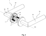
- Fig. 2 shows a view of the assembled door locking system 1 according to the invention.
- the two mounting plates 4a and 4b are screwed together via the two mounting screws 5 and are thus axially spaced from one another and coaxially aligned.
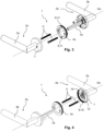
- Fig. 3 and Fig. 4 show partially exploded views of the door locking system 1 according to the invention.
- the first door handle unit 2a and the second door handle unit 2b are shown during assembly of the door locking system 1.
- the first Door handle unit 2a is assembled ready for assembly and the second door handle unit 2b is pre-assembled on the mounting plate 4b.
- the first mounting plate 4a is first secured to the second mounting plate 4b with the pre-assembled second door handle unit 2b using the screws 5.
- the first door handle unit 2a or the first door handle 3a is then brought into engagement with the polygonal pin 18 and moved axially to the mounting plate 4a.
- the cover cap 7 is screwed to the first mounting plate 4a.
- the first door handle 3a is then screwed to the polygonal pin 18 using the grub screw - not shown here - and the first door handle unit 2a is thereby secured axially to the mounting plate 4a.
- Fig. 5 and Fig. 6 show partially exploded views of the first door handle unit 2a of the door locking system 1 according to the invention on the first mounting plate 4a.
- a handle stop 19 is formed on the handle support plate 8, with which the stop element 14 of the swivel unit 12 interacts via the return spring 13.
Landscapes
- Engineering & Computer Science (AREA)
- Mechanical Engineering (AREA)
- Wing Frames And Configurations (AREA)
- Lock And Its Accessories (AREA)
- Special Wing (AREA)
Description
- Die Erfindung betrifft ein Türschließsystem zum Öffnen und zum Schließen einer Tür nach dem Oberbegriff des Anspruchs 1.
- Ein Türschließsystem umfasst üblicherweise eine erste Türgriffeinheit mit einem ersten Türgriff und eine zweite Türgriffeinheit mit einem zweiten Türgriff. Zudem weist das Türschließsystem üblicherweise zwei Montageplatten, die durch die Tür hindurch miteinander verschraubt sind. Die Türgriffe sind miteinander mittels eines Vielkantstifts festverbunden und an den Montageplatten schwenkbar angeordnet. Des Weiteren umfasst das Türschließsystem zwei Abdeckkappen, die die Montageplatten nach außen abdecken und mit den Montageplatten festverbunden sind. Nachteiligerweise können die Abdeckkappen bei einem herkömmlichen Türschließsystem von der Montageplatte vereinfacht gelöst werden. Dadurch kann der Zugang zum Inneren des Türschließsystems verschafft und das Türschließsystem beschädigt werden und/oder die Abdeckkappe weggebracht werden und/oder mit der gelösten Abdeckkappe der Türgriff beschädigt/zerkratz werden. Insbesondere in einem öffentlich zugänglichen Gebäude - wie beispielweise einer Schule - kann das beschriebene Problem hochrelevant sein.
-
EP 2 840 203 A1 offenbart ein Türschließsystem und eine Türgriffeinheit mit einem Türgriff und einer Abdeckkappe. Hier ist die Abdeckkappe zweiteilig und weist ein an dem Türgriff befestigtes Teil und einen lösbaren Blendring auf. -
DE 10 2019 200 115 A1 offenbart ein Türschließsystem eine Türgriffeinheit mit einem Türgriff und einer Abdeckkappe. Die Abdeckkappe ist über eine von außen erreichbare Einheit mit einer Montageplatte drehfest verbunden, so dass beim Betätigen der Einheit die Abdeckkappe an dem Türgriff verdreht werden kann. -
DE 10 2013 205 061 A1 offenbart ein Türschließsystem eine Türgriffeinheit einem Türgriff und einer Abdeckkappe. Hier kann die Abdeckkappe an dem Türgriff frei verdreht werden. -
KR 2004 0059933 A -
EP 2 182 144 A1 offenbart ein Türschließsystem und eine Türgriffeinheit einem Türgriff und einer Abdeckkappe. Die Abdeckkappe ist mit dem Türgriff über eine Griffträgerplatte drehbar verbunden. Dadurch kann die Abdeckkappe an dem Türgriff frei verdreht werden. -
DE 10 2018 201 186 A1 offenbart ein Türschließsystem und eine Türgriffeinheit einem Türgriff und einer Abdeckkappe. Die Abdeckkappe ist zweiteilig und umfasst einen an dem Türgriff befestigten Teil und einen Blendring. - Die Aufgabe der Erfindung ist es daher, für ein Türschließsystem der gattungsgemäßen Art eine verbesserte oder zumindest alternative Ausführungsform anzugeben, bei der die beschriebenen Nachteile überwunden werden.
- Diese Aufgabe wird erfindungsgemäß durch den Gegenstand des unabhängigen Anspruchs 1 gelöst. Vorteilhafte Ausführungsformen sind Gegenstand der abhängigen Ansprüche.
- Ein Türschließsystem ist zum Öffnen und zum Schließen einer Tür vorgesehen. Das Türschließsystem weist eine erste Türgriffeinheit mit einem ersten um eine Schwenkachse schwenkbaren Türgriff und mit einer quer zur Schwenkachse ausgerichteten Abdeckkappe auf. Das Türschließsystem weist auch eine zweite zu der ersten Türgriffeinheit identische oder von der ersten Türgriffeinheit abweichende Türgriffeinheit mit einem zweiten Türgriff auf. Des Weiteren weist das Türschließsystem eine quer zur Schwenkachse ausgerichtete erste Montageplatte und eine quer zur Schwenkachse ausgerichtete zweite Montageplatte auf. Die erste Montageplatte und die zweite Montageplatte sind miteinander axialfest und drehfest verbunden. Dabei sind die erste Türgriffeinheit an der ersten Montageplatte axialfest und die zweite Türgriffeinheit an der zweiten Türgriffeinheit axialfest angeordnet. Dabei ist die Abdeckkappe mit der ersten Montageplatte axialfest und mit dem ersten Türgriff axialfest und drehbar verbunden. Die Abdecckappe ist dabei ausschließlich zusammen mit der gesamten ersten Türgriffeinheit axial von der ersten Montageplatte lösbar.
- Erfindungsgemäß ist vorgesehen, dass die Abdeckkappe ein die Schwenkachse umlaufendes Gewinde und die erste Montageplatte ein die Schwenkachse umlaufendes Gegengewinde aufweisen. Die Abdeckkappe und die erste Montageplatte sind dann miteinander verschraubt. Die Schraubverbindung ist dabei nur dann herstellbar und lösbar, wenn die axialfeste Anordnung der ersten Türgriffeinheit an der ersten Montageplatte - beispielweise durch eine axialfeste Verbindung der Türgriffe mit dem Vielkantstift - nicht hergestellt ist. Danach kann die Abdeckkappe von der ersten Montageplatte nicht mehr abgeschraubt werden. Die Schraubverbindung stabilisiert zusätzlich die axialfeste Verbindung zwischen der ersten Türgriffeinheit und der ersten Montageplatte. H
- Erfindungsgemäß ist die Abdeckkappe einstückig und topfförmig ausgebildet. Die Abdeckkappe deckt dann die Montageplatte an einer dem ersten Türgriff zugewandten und quer zur Schwenkachse ausgerichteten Seite und an einer die Schwenkachse umlaufenden Seite nach außen ab. Im Vergleich zu herkömmlichen mehrteiligen Abdeckkappen verbleiben bei der einteiligen Abdeckkappe keine Spalte, über die ein Zugang in das Innere des Türschließsystems verschafft werden könnte. Zudem kann dadurch die äußere Wirkung des Türschließsystems verbessert werden.
- Im Zusammenhang mit der vorliegenden Erfindung beziehen sich die Begriffe "axial" und "radial" stets auf die Schwenkachse des ersten Türgriffs und/oder des zweiten Türgriffs.
- Die Abdeckkappe kann mit der ersten Montageplatte unmittelbar axialfest verbunden sein. Mit anderen Worten kann zwischen der Abdeckkappe und der ersten Montageplatte ein direkter Kontakt bestehen bzw. können die Abdeckkappe und die erste Montageplatte ohne weitere Elemente miteinander im axialfesten Eingriff stehen. So kann die Abdeckkappe mit der ersten Montageplatte verschraubt sein. Mit dem ersten Türgriff kann die Abdeckkappe unmittelbar oder mittelbar verbunden sein. So kann die Abdeckkappe mit dem ersten Türgriff mittelbar über einen Tragring drehbar und axialfest verbunden sein. Der Tragring kann dabei radial und/oder axial zwischen dem ersten Türgriff und der Abdeckkappe angeordnet sein und die Abdeckkappe drehbar und axialfest tragen. Die Abdeckkappe mit dem ersten Türgriff kann also unabhängig von der axialen Festlegung der Abdeckkappe an der Montageplatte axialfest und drehbar verbunden sein. Mit anderen Worten bleibt die Abdeckkappe mit dem ersten Türgriff axialfest und drehbar verbunden, auch wenn die Abdeckkappe von der Montageplatte axial gelöst ist. Es versteht sich, dass die axialfeste Verbindung stets eine lösbare axialfeste Verbindung ist. Das ist dadurch bedingt, dass das Türschließsystem aus einzelnen separaten Elementen zusammengesetzt ist, die bei einer Demontage voneinander gelöst werden können. Wesentlich ist es jedoch, ob die Elemente bei der Demontage einzeln von anderen noch montierten Elementen lösbar sind.
- In dem erfindungsgemäßen Türschließsystem kann die Abdeckkappe von der Montageplatte nicht gelöst werden, sobald eine axialfeste Anordnung zwischen der ersten Montageplatte und der gesamten Türschließeinheit zum Lösen nicht freigegeben ist. Dadurch kann von außen kein vereinfachter Zugang zum Inneren des Türschließsystems verschafft und das Türschließsystem beschädigt werden. Zudem kann die Abdeckkappe nicht vereinfacht gelöst/weggebracht werden und/oder mit der gelösten Abdeckkappe der Türgriff beschädigt/zerkratz werden.
- Das erfindungsgemäße Türschließsystem ist zum Anordnen an einer Tür vorgesehen und ausgelegt. Ist das Türschließsystem an einer Tür montiert, so sind die beiden Montageplatten quer zur Schwenkachse und koaxial zueinander ausgerichtet und beidseitig an der Tür anliegend angeordnet. Die Montageplatten können dabei durch die Tür hindurch mittels zwei Montageschrauben miteinander verschraubt sein. Für die Montageschrauben können in der einen Montageplatte zwei Durchgangsöffnungen und in der anderen Montageplatte zwei Schrauböffnungen vorgesehen sein. Die Montageschrauben können dann durch die Durchgangsöffnungen zu der anderen Montageplatte hindurchgehen und mit der anderen Montageplatte über die Schrauböffnungen verschraubt sein. Dazu können die Montageschrauben ein Gewinde und die Schrauböffnungen ein dazu komplementäres Gegengewinde aufweisen. Die Montageschrauben können in der Tür bzw. in einem Schloss innerhalb der Tür radial und axial verschiebefest und drehfest angeordnet sein und dadurch die Montageplatten auch radial und axial verschiebefest und drehfest an der Tür montiert sein.
- Vorteilhafterweise kann vorgesehen sein, dass das Türschließsystem einen parallel zur Schwenkachse ausgerichteten Vielkantstift aufweist. Der erste Türgriff und der zweite Türgriff sind dabei mit dem Vielkantstift jeweils axialfest und drehfest verbunden. Dazu können die beiden Türgriffe jeweils mittels einer radial gerichteten Madenschraube mit dem Vielkantstift verbunden sein. Dabei verbindet der Vielkantstift die beiden Türgriffe wirksam miteinander, so dass die beiden Türgriffe gemeinsam um die Schwenkachse schwenkbar sind. Dadurch kann das Türschließsystem bzw. ein mit dem Türschließsystem über den Vielkantstift wirksam verbundenes Schloss mit einem der beiden Türgriffe betätigt werden.
- Sind die beiden Türgriffe axialfest an dem Vielkantstift befestigt, so legt der Vielkantstift die beiden Türgriffe in einem vordefinierten axialen Abstand zueinander fest. Entsprechend legt der Vielkantstift den ersten Türgriff relativ zu der ersten Montageplatte und den zweiten Türgriff relativ zu der zweiten Montageplatte axial fest. Dadurch wird nun die oben beschriebene axialfeste Anordnung der ersten Türgriffeinheit an der ersten Montageplatte und der zweiten Türgriffeinheit an der zweiten Montageplatte erreicht.
- Vorteilhafterweise kann die Abdeckkappe von der ersten Montageplatte nach dem axialfesten Verbinden des Vielkantstifts mit dem ersten Türgriff und mit dem zweiten Türgriff axial nicht lösbar sein. Wie oben bereits erläutert, legt der Vielkantstift den ersten Türgriff relativ zu der ersten Montageplatte axialfest. Da die Abdeckkappe axialfest mit dem ersten Türgriff verbunden ist, ist auch die Abdeckkappe relativ zu der ersten Montageplatte axialfest angeordnet. Die beschriebene axialfeste Anordnung der ersten Türgriffeinheit an der ersten Montageplatte ist dabei unabhängig von der Abdeckkappe herstellbar und lösbar. Sobald also die Verbindung zwischen dem Türgriff und dem Vielkantstift hergestellt ist, kann die an dem ersten Türgriff axialfest angeordnete Abdeckkappe von der ersten Montageplatte nicht gelöst werden.
- Vorteilhafterweise kann die erste Türgriffeinheit einen Tragring aufweisen, wobei der Tragring radial und/oder axial zwischen der Abdeckkappe und dem ersten Türgriff angeordnet ist und die Abdeckkappe drehbar trägt. Dadurch kann ein unmittelbarer Kontakt zwischen der Abdeckkappe und dem ersten Türgriff vermieden werden und dadurch der erste Türgriff beim Transport/Montage nicht unerwünscht beschädigt/zerkratzt werden. Sind der erste Türgriff und die Abdecckappe aus Metall geformt, so kann durch den Tragring vorteilhaft der Metall-auf-Metall-Kontakt vermieden werden. Zudem bildet der Tragring ein Gleitlager zwischen dem ersten Türgriff und der Abdeckkappe und der erste Türgriff kann sich relativ zu der Abdeckkappe leicht drehen.
- Bei einer vorteilhaften Weiterbildung des Türschließsystems kann vorgesehen sein, dass die erste Türgriffeinheit eine Griffträgerplatte aufweist. Die Griffträgerplatte ist dabei axial zwischen der Montageplatte und der Abdeckkappe angeordnet. Zudem ist die Griffträgerplatte mit dem ersten Türgriff axialfest und drehbar und mit der Montageplatte drehfest verbunden. Mittels der Griffträgerplatte kann die erste Türgriffeinheit wirksam mit der an der Tür bereits montierten ersten Montageplatte verbunden werden. Über die Griffträgerplatte werden dabei die Abdeckkappe drehbar und der erste Türgriff schwenkbar an der ersten Montageplatte angeordnet. Ist die axialfeste Anordnung der ersten Türgriffeinheit an der ersten Montageplatte - beispielweise durch eine axialfeste Verbindung der Türgriffe mit dem Vielkantstift - hergestellt, so ist die Griffträgerplatte und dadurch auch die Abdeckkappe und der erste Türgriff zusätzlich auch axialfest an der ersten Montageplatte angeordnet.
- Zusätzlich kann vorgesehen sein, dass die Griffträgerplatte mit der ersten Montageplatte über eine formschlüssige Formschlusseinheit mit wenigstens einem axial ausgerichteten Pin und mit wenigstens einer zu dem Pin komplementären Öffnung gebildet ist. Die Öffnung kann in der Griffträgerplatte und der Pin kann an der ersten Montageplatte oder umgekehrt ausgebildet sein. Der Pin greift zweckgemäß axial in die Öffnung ein, so dass die Griffträgerplatte und die erste Montageplatte über die Formschlusseinheit drehfest - jedoch axial lösbar - miteinander verbunden sind.
- Bei einer möglichen Ausführungsform des Türschließsystems kann vorgesehen sein, dass die erste Türgriffeinheit eine Schwenkeinheit aufweist. Die Schwenkeinheit verbindet dabei den ersten Türgriff schwenkbar mit der Griffträgerplatte. Mit anderen Worten legt die Schwenkeinheit den ersten Türgriff schwenkbar in der ersten Türgriffeinheit fest. Vorteilhafterweise kann die Schwenkeinheit an der oben beschriebenen Griffträgerplatte angeordnet sein und den ersten Türgriff an der Griffträgerplatte schwenkbar anordnen. Die Schwenkeinheit kann dabei eine Rückstellfeder aufweisen. Der erste Türgriff kann dann an der Griffträgerplatte aus einer Schließposition in eine Offenposition entgegen einer Federkraft der Rückstellfeder manuell und aus der Offenposition in die Schließposition mittels der Rückstellfeder automatisch verschwenkbar sein.
- In der vorangegangenen Beschreibung wurde die erste Türgriffeinheit ausführlich beschrieben. Wie oben bereits erläutert, kann in dem Türschließsystem die zweite Türgriffeinheit zu der ersten Türgriffeinheit identisch oder abweichend aufgebaut sein. Bei den identisch aufgebauten Türgriffeinheiten sind die Türschließeinheiten jedoch bezüglich der Türfläche gespiegelt zueinander ausgebildet.
- Weitere wichtige Merkmale und Vorteile der Erfindung ergeben sich aus den Unteransprüchen, aus den Zeichnungen und aus der zugehörigen Figurenbeschreibung anhand der Zeichnungen.
- Es versteht sich, dass die vorstehend genannten und die nachstehend noch zu erläuternden Merkmale nicht nur in der jeweils angegebenen Kombination, sondern auch in anderen Kombinationen verwendbar sind ohne den Rahmen der durch die Ansprüche definierte Erfindung zu verlassen.
- Bevorzugte Ausführungsbeispiele der Erfindung sind in den Zeichnungen dargestellt und werden in der nachfolgenden Beschreibung näher erläutert, wobei sich gleiche Bezugszeichen auf gleiche oder ähnliche oder funktional gleiche Komponenten beziehen.
- Es zeigen, jeweils schematisch
- Fig. 1
- eine teilweise Explosionsansicht eines erfindungsgemäßen Türschließsystems;
- Fig. 2
- eine Ansicht eines montierten erfindungsgemäßen Türschließsystems;
- Fig. 3 und 4
- teilweise Explosionsansichten des erfindungsgemäßen Türschließsystems;
- Fig. 5 und 6
- teilweise Explosionsansichten einer ersten Türgriffeinheit des erfindungsgemäßen Türschließsystems und einer ersten Montageplatte.
-
Fig. 1 zeigt eine teilweise Explosionsansicht eines erfindungsgemäßen Türschließsystems 1. Das Türschließsystem 1 weist dabei eine erste Türgriffeinheit 2a mit einem ersten Türgriff 3a und eine zweite Türgriffeinheit 2b mit einem zweiten Türgriff 3b auf. Die Türgriffe 3a und 3b sind dabei um eine gemeinsame Schwenkachse SA schwenkbar. Zudem weist das Türschließsystem 1 eine erste Montageplatte 4a und eine zweite Montageplatte 4b auf, wobei die jeweiligen Montageplatten 4a und 4b quer zur Schwenkachse SA und axial zueinander beabstandet angeordnet sind. Die Montageplatten 4a und 4b sind über zwei Montageschrauben 5 durch eine Tür - hier zur Übersichtlichkeit nicht gezeigt - miteinander verschraubt und dadurch an der Tür drehfest und axialfest befestigt. Die jeweiligen Türgriffeinheiten 2a und 2b sind an den jeweiligen Montageplatten 4a und 4b voneinander abgewandt axialfest angeordnet. - In
Fig. 1 sind die erste Türgriffeinheit 2a und die erste Montageplatte 4a voneinander gelöst in Explosionsansicht und die zweite Türgriffeinheit 2b mit der Montageplatte 4b miteinander verbunden. Im Folgenden wird der Aufbau der ersten Türgriffeinheit 2a ausführlich erörtert. Die zweite Türgriffeinheit 2b kann dabei zu der ersten Türgriffeinheit 2a identisch oder abweichend ausgebildet sein. - Die erste Türgriffeinheit 2a weist dabei einen Tragring 6 und eine Abdeckkappe 7 auf, wobei der Tragring 6 radial und axial zwischen der Abdeckkappe 7 und dem ersten Türgriff 3a angeordnet ist. Zwischen der Abdeckkappe 7 und der ersten Montageplatte 4a ist eine Griffträgerplatte 8 angeordnet, die mit der Montageplatte 4a über eine Formschlusseinheit 9 drehfest verbindbar ist. Die Formschlusseinheit 9 ist dabei durch Öffnungen 10 in der Griffträgerplatte 8 und durch Pins 11 an der ersten Montageplatte 4a abgebildet. Zudem weist die erste Türgriffeinheit 2a eine Schwenkeinheit 12 mit einer Rückstellfeder 13 und einem Anschlagelement 14 auf. Zum Befestigen der einzelnen Elemente an dem Türgriff 3a weist die erste Türschließeinheit 2a zudem eine Unterlegscheibe 15 und ein Befestigungsring 16 auf. Durch die Unterlegscheibe 15 können vorteilhafterweise Fertigungsabweichungen und Fertigungstoleranzen ausgeglichen werden. Denkbar ist es auch, dass die erste Türschließeinheit 2a mehrere axial zueinander benachbarte Unterlegscheiben 15 aufweist.
- In der ersten Türgriffeinheit 2a sind der Tragring 6, die Abdeckkappe 7, die Griffträgerplatte 8, die Rückstellfeder 13, das Anschlagelement 14, die Unterlegscheibe 15 und der Befestigungsring 16 axial von dem Türgriff 3a zu der ersten Montageplatte 4a in der genannten Reihenfolge einander folgend angeordnet. Dabei sind die einzelnen Elemente an dem Türgriff 3a zwischen einem die Schwenkachse SA umlaufenden Anschlag 17 und dem Befestigungsring 16 axialfest angeordnet. Der Befestigungsring 16 ist dabei in einer umlaufenden Rille 20 des Türgriffs 3a axialfest festgelegt.
- Dabei ist die Abdeckkappe 7 drehbar an dem Türgriff 3a angeordnet und kann mit der Montageplatte 4a über ein seitliches Gewinde verschraubt sein. Die Schwenkeinheit 12 legt den Türgriff 3a an der Griffträgerplatte 8 schwenkbar fest, wobei der Türgriff 3a entgegen einer Federkraft der Rückstellfeder 13 aus einer Schließposition in eine Offenposition manuell und mittels der Rückstellfeder 13 aus der Offenposition in die Schließposition automatisch verschwenkbar ist. Die Grifftragplatte 8 ist über die Formschlusseinheit 9 drehfest an der Montageplatte 4a festgelegt. Dadurch ist der Türgriff 3a schwenkbar an der Montageplatte 4a und an der Tür - hier nicht gezeigt - angeordnet.
- Die axialfeste Anordnung der ersten Türgriffeinheit 2a an der ersten Montageplatte 4a wird durch einen Vielkantstift 18 des Türschließsystems 1 erreicht. Der Vielkantstift 18 greift dabei axial in die beiden Türgriffe 3a und 3b ein und ist mit diesen durch seine Form formschlüssig drehfest verbunden. Durch den Vielkantstift 18 sind die beiden Türgriffe 3a und 3b beim Verschwenken eines der Türgriffe 3a und 3b gemeinsam um die Schwenkachse SA schwenkbar. Der erste Türgriff 3a und dadurch die gesamte Türgriffeinheit 2a sind über eine Madenschraube - hier nicht gezeigt - auf eine dem Fachmann bekannte Weise axialfest mit dem Vielkantstift 18 verbunden. Dadurch ist nun die erste Türgriffeinheit 2a und insbesondere die Abdeckkappe 7 an der Montageplatte 4a axialfest angeordnet. Die oben genannte Schraubverbindung zwischen der Montageplatte 4a und der Abdeckkappe 7 legt die Türschließeinheit 2a zusätzlich an der Montageplatte 4a fest. Da jedoch die Abdeckkappe 7 axialfest mit dem Türgriff 3a verbunden ist, kann die Abdeckkappe 7 von der Montageplatte 4a nicht gelöst werden, solange die axialfeste Verbindung zwischen dem Vielkantstift 18 und dem ersten Türgriff 3a nicht gelöst ist.
- Erfindungsgemäß ist die Abdeckkappe 7 einteilig ausgebildet und axialfest mit dem Türgriff 3a verbunden, so dass die Abdeckkappe 7 ohne den Türgriff 3a bzw. solange die Verbindung zwischen dem Vielkantstift 18 und dem ersten Türgriff 3a nicht gelöst ist, nicht lösbar ist. In dem erfindungsgemäßen Türschließsystem 1 kann demnach von außen kein vereinfachter Zugang zum Inneren des Türschließsystems 1 verschafft und das Türschließsystem 1 beschädigt werden. Zudem kann die Abdeckkappe 7 nicht vereinfacht gelöst/weggebracht werden und/oder mit der gelösten Abdeckkappe 7 der Türgriff 3a beschädigt/zerkratzt werden.
-
Fig. 2 zeigt eine Ansicht des montierten erfindungsgemäßen Türschließsystems 1. Hier ist besonders gut erkennbar, dass die beiden Montageplatten 4a und 4b über die beiden Montageschrauben 5 miteinander verschraubt und dadurch zueinander axial beabstandet und koaxial ausgerichtet sind. -
Fig. 3 und Fig. 4 zeigen teilweise Explosionsansichten des erfindungsgemäßen Türschließsystems 1. Hier sind die erste Türgriffeinheit 2a und die zweite Türgriffeinheit 2b bei der Montage des Türschließsystems 1 gezeigt. Dabei ist die erste Türgriffeinheit 2a montagefertig aufgebaut und die zweite Türgriffeinheit 2b an der Montageplatte 4b vormontiert. Bei der Montage des Türschließsystems 1 an der Tür - hier nicht gezeigt - wird nun zuerst die erste Montageplatte 4a an der zweiten Montageplatte 4b mit der vormontierten zweiten Türgriffeinheit 2b mittels der Schrauben 5 festgelegt. Danach wird die erste Türgriffeinheit 2a bzw. der erste Türgriff 3a mit dem Vielkantstift 18 in Eingriff gebracht und axial zu der Montageplatte 4a bewegt. Gleichzeitig wird die Abdeckkappe 7 mit der ersten Montageplatte 4a verschraubt. Anschließend wird der erste Türgriff 3a mit dem Vielkantstift 18 über die Madenschraube - hier nicht gezeigt - verschraubt und dadurch die erste Türgriffeinheit 2a axial an der Montageplatte 4a festgelegt. -
Fig. 5 und Fig. 6 zeigen teilweise Explosionsansichten der ersten Türgriffeinheit 2a des erfindungsgemäßen Türschließsystems 1 an der ersten Montageplatte 4a. InFig. 5 ist besonders gut erkennbar, dass an der Griffträgerplatte 8 ein Griffanschlag 19 ausgebildet ist, mit dem das Anschlagelement 14 der Schwenkeinheit 12 über die Rückstellfeder 13 zusammenwirkt.
Claims (8)
- Türschließsystem (1) zum Öffnen und zum Schließen einer Tür,- wobei das Türschließsystem (1) eine erste Türgriffeinheit (2a) mit einem ersten um eine Schwenkachse (SA) schwenkbaren Türgriff (3a) und mit einer quer zur Schwenkachse (SA) ausgerichteten Abdeckkappe (7) aufweist,- wobei das Türschließsystem (1) eine zu der ersten Türgriffeinheit (2a) identische oder von der ersten Türgriffeinheit (2a) abweichende zweite Türgriffeinheit (2b) mit einem zweiten Türgriff (3b) aufweist,- wobei das Türschließsystem (1) eine quer zur Schwenkachse (SA) ausgerichtete erste Montageplatte (4a) und eine quer zur Schwenkachse (SA) ausgerichtete zweite Montageplatte (4b) aufweist,- wobei die erste Montageplatte (4a) und die zweite Montageplatte (4b) miteinander axialfest und drehfest verbunden sind, und- wobei die erste Türgriffeinheit (2a) an der ersten Montageplatte (4a) axialfest und die zweite Türgriffeinheit (2b) an der zweiten Türgriffeinheit (4b) axialfest angeordnet sind,- wobei die Abdeckkappe (7) mit der ersten Montageplatte (4a) axialfest und mit dem ersten Türgriff (3a) axialfest und drehbar verbunden ist, und- wobei die Abdeckkappe (7) ausschließlich zusammen mit dem ersten Türgriff (3a) axial von der ersten Montageplatte (4a) lösbar ist,
dadurch gekennzeichnet,- dass die Abdeckkappe (7) ein die Schwenkachse (SA) umlaufendes Gewinde und die erste Montageplatte (4a) ein die Schwenkachse (SA) umlaufendes Gegengewinde aufweisen, und- dass die Abdeckkappe (7) und die erste Montageplatte (4a) miteinander verschraubt sind, und- dass die Abdeckkappe (7) einstückig und topfförmig ausgebildet ist und die Montageplatte (4a) an einer dem ersten Türgriff (3a) zugewandten und quer zur Schwenkachse (SA) ausgerichteten Seite und an einer die Schwenkachse (SA) umlaufenden Seite nach außen abdeckt. - Türschließsystem nach Anspruch 1,
dadurch gekennzeichnet,- dass das Türschließsystem (1) einen parallel zur Schwenkachse (SA) ausgerichteten Vielkantstift (18) aufweist, und- dass der erste Türgriff (3a) und der zweite Türgriff (3b) mit dem Vielkantstift (18) jeweils axialfest und drehfest verbunden sind. - Türschließsystem nach Anspruch 2,
dadurch gekennzeichnet,
dass nach dem axialfesten Verbinden des Vielkantstifts (18) mit dem ersten Türgriff (3a) und mit dem zweiten Türgriff (3b) die Abdeckkappe (7) von der ersten Montageplatte (4a) axial nicht lösbar ist. - Türschließsystem nach einem der vorangehenden Ansprüche,
dadurch gekennzeichnet,
dass die erste Türgriffeinheit (2a) einen Tragring (6) aufweist, wobei der Tragring (6) radial und/oder axial zwischen der Abdeckkappe (7) und dem ersten Türgriff (3a) angeordnet ist und die Abdeckkappe (7) drehbar trägt. - Türschließsystem nach einem der vorangehenden Ansprüche,
dadurch gekennzeichnet,- dass die erste Türgriffeinheit (2a) eine Griffträgerplatte (8) aufweist, die axial zwischen der Montageplatte (4a) und der Abdeckkappe (7) angeordnet ist, und- dass die Griffträgerplatte (8) mit dem ersten Türgriff (3a) axialfest und drehbar und mit der Montageplatte (4a) drehfest verbunden ist. - Türschließsystem nach Anspruch 5,
dadurch gekennzeichnet,- dass die Griffträgerplatte (8) mit der ersten Montageplatte (4a) über eine formschlüssige Formschlusseinheit (9) mit wenigstens einem axial ausgerichteten Pin (11) und mit wenigstens einer zu dem Pin (11) komplementären Öffnung (10) gebildet ist, und- dass die Öffnung (10) in der Griffträgerplatte (8) und der Pin (11) an der ersten Montageplatte (4a) oder umgekehrt ausgebildet sind. - Türschließsystem nach einem der vorangehenden Ansprüche,
dadurch gekennzeichnet,
dass die erste Türgriffeinheit (2a) eine Schwenkeinheit (12) aufweist, wobei die Schwenkeinheit (12) den ersten Türgriff (3a) mit der Griffträgerplatte (8) schwenkbar verbindet. - Türschließsystem nach Anspruch 5 und 7,
dadurch gekennzeichnet,- dass die Schwenkeinheit (12) eine Rückstellfeder (13) aufweist, und- dass der erste Türgriff (3a) an der Griffträgerplatte (8) aus einer Schließposition in eine Offenposition entgegen einer Federkraft der Rückstellfeder (13) manuell verschwenkbar ist, und- dass der erste Türgriff (3a) an der Griffträgerplatte (8) aus der Offenposition in die Schließposition mittels der Rückstellfeder (13) automatisch verschwenkbar ist.
Applications Claiming Priority (1)
| Application Number | Priority Date | Filing Date | Title |
|---|---|---|---|
| DE102021210229.8A DE102021210229A1 (de) | 2021-09-15 | 2021-09-15 | Türschließsystem |
Publications (3)
| Publication Number | Publication Date |
|---|---|
| EP4159957A1 EP4159957A1 (de) | 2023-04-05 |
| EP4159957B1 true EP4159957B1 (de) | 2025-01-01 |
| EP4159957C0 EP4159957C0 (de) | 2025-01-01 |
Family
ID=83059257
Family Applications (1)
| Application Number | Title | Priority Date | Filing Date |
|---|---|---|---|
| EP22191915.2A Active EP4159957B1 (de) | 2021-09-15 | 2022-08-24 | Türschliesssystem |
Country Status (2)
| Country | Link |
|---|---|
| EP (1) | EP4159957B1 (de) |
| DE (1) | DE102021210229A1 (de) |
Families Citing this family (1)
| Publication number | Priority date | Publication date | Assignee | Title |
|---|---|---|---|---|
| US20240401370A1 (en) * | 2023-06-05 | 2024-12-05 | Assa Abloy Americas Residential Inc. | Lockset assembly with retainer and method of installing the same |
Family Cites Families (7)
| Publication number | Priority date | Publication date | Assignee | Title |
|---|---|---|---|---|
| US4569547A (en) | 1984-02-27 | 1986-02-11 | Baldwin Hardware Corporation | Door handle mount |
| KR100478273B1 (ko) * | 2002-12-30 | 2005-03-28 | (주)베스트메탈라인 | 레버 록 |
| ATE494440T1 (de) * | 2008-10-31 | 2011-01-15 | Almar S P A | Tür- oder fensterbeschlag |
| NL2008525C2 (nl) * | 2012-03-22 | 2013-09-25 | Artitec B V | Bedieningsorgaan voor een paneel, samenstel van twee bedieningsorganen en een werkwijze voor het klemvast tegen een paneel positioneren van het bedieningsorgaan. |
| EP2840203B1 (de) * | 2013-08-22 | 2016-02-24 | ALMAR s.p.a. | Tür- oder Fensterbeschlag mit mehrteiliger Abdeckblende |
| DE102018201186A1 (de) | 2018-01-25 | 2019-07-25 | Karcher Gmbh | Türschließsystem |
| DE102019200115B4 (de) * | 2019-01-08 | 2022-12-01 | Karcher Gmbh | Türschließsystem |
-
2021
- 2021-09-15 DE DE102021210229.8A patent/DE102021210229A1/de active Pending
-
2022
- 2022-08-24 EP EP22191915.2A patent/EP4159957B1/de active Active
Also Published As
| Publication number | Publication date |
|---|---|
| EP4159957A1 (de) | 2023-04-05 |
| DE102021210229A1 (de) | 2023-03-16 |
| EP4159957C0 (de) | 2025-01-01 |
Similar Documents
| Publication | Publication Date | Title |
|---|---|---|
| EP3859102B1 (de) | Türschliesssystem | |
| DE3033496C2 (de) | In Offenstellung verrastbares Türschließergestänge | |
| EP4159957B1 (de) | Türschliesssystem | |
| EP3277899B1 (de) | Türgriffanordnung für ein kraftfahrzeug | |
| EP2169163B1 (de) | Höhenverstellbares Band | |
| EP0845568B1 (de) | Aushängbares Türscharnier für Kraftwagentüren | |
| EP1643060A2 (de) | Scharnieraufbau und Schutzvorrichtung mit einem Scharnieraufbau | |
| DE102019200115B4 (de) | Türschließsystem | |
| EP1659250B1 (de) | Fenster, Tür oder dergleichen mit einer Eckumlenkung | |
| EP0900904A2 (de) | Scharnier für Behälterabdeckungen | |
| DE102019128325B3 (de) | Scharnier | |
| EP2284342A2 (de) | Gelenkband mit gekerbter Stützfläche | |
| DE10130268B4 (de) | Schließanlage für Fahrzeugtüren | |
| EP3763901A1 (de) | Türschliesssystem | |
| EP3354824B1 (de) | Rollenzunge | |
| CH716756B1 (de) | Montageeinrichtung zur lösbaren Montage eines Garniturteils auf einem WC-Körper. | |
| EP0356772B1 (de) | Treibstangenschloss | |
| EP1702720B1 (de) | Spannvorrichtung | |
| WO2002008550A2 (de) | An einer tür montierbarer griffbeschlag, insbesondere für fahrzeuge | |
| DE102004025389B4 (de) | Scharnier zum schwenkbaren Haltern einer Tür | |
| DE3506870A1 (de) | Tuerverschluss mit hebelfoermiger versenkbarer handhabe, insbesondere an schaltschranktueren | |
| DE20105545U1 (de) | Band für Türen, Fenster o.dgl. | |
| DE3407701A1 (de) | Schaltschrank mit einer tuer | |
| DE102018201186A1 (de) | Türschließsystem | |
| AT404493B (de) | Scharnier |
Legal Events
| Date | Code | Title | Description |
|---|---|---|---|
| PUAI | Public reference made under article 153(3) epc to a published international application that has entered the european phase |
Free format text: ORIGINAL CODE: 0009012 |
|
| STAA | Information on the status of an ep patent application or granted ep patent |
Free format text: STATUS: THE APPLICATION HAS BEEN PUBLISHED |
|
| AK | Designated contracting states |
Kind code of ref document: A1 Designated state(s): AL AT BE BG CH CY CZ DE DK EE ES FI FR GB GR HR HU IE IS IT LI LT LU LV MC MK MT NL NO PL PT RO RS SE SI SK SM TR |
|
| STAA | Information on the status of an ep patent application or granted ep patent |
Free format text: STATUS: REQUEST FOR EXAMINATION WAS MADE |
|
| 17P | Request for examination filed |
Effective date: 20231004 |
|
| RBV | Designated contracting states (corrected) |
Designated state(s): AL AT BE BG CH CY CZ DE DK EE ES FI FR GB GR HR HU IE IS IT LI LT LU LV MC MK MT NL NO PL PT RO RS SE SI SK SM TR |
|
| GRAP | Despatch of communication of intention to grant a patent |
Free format text: ORIGINAL CODE: EPIDOSNIGR1 |
|
| STAA | Information on the status of an ep patent application or granted ep patent |
Free format text: STATUS: GRANT OF PATENT IS INTENDED |
|
| INTG | Intention to grant announced |
Effective date: 20241010 |
|
| GRAS | Grant fee paid |
Free format text: ORIGINAL CODE: EPIDOSNIGR3 |
|
| GRAA | (expected) grant |
Free format text: ORIGINAL CODE: 0009210 |
|
| STAA | Information on the status of an ep patent application or granted ep patent |
Free format text: STATUS: THE PATENT HAS BEEN GRANTED |
|
| AK | Designated contracting states |
Kind code of ref document: B1 Designated state(s): AL AT BE BG CH CY CZ DE DK EE ES FI FR GB GR HR HU IE IS IT LI LT LU LV MC MK MT NL NO PL PT RO RS SE SI SK SM TR |
|
| REG | Reference to a national code |
Ref country code: GB Ref legal event code: FG4D Free format text: NOT ENGLISH |
|
| REG | Reference to a national code |
Ref country code: DE Ref legal event code: R096 Ref document number: 502022002561 Country of ref document: DE |
|
| REG | Reference to a national code |
Ref country code: CH Ref legal event code: EP |
|
| REG | Reference to a national code |
Ref country code: IE Ref legal event code: FG4D Free format text: LANGUAGE OF EP DOCUMENT: GERMAN |
|
| U01 | Request for unitary effect filed |
Effective date: 20250120 |
|
| U07 | Unitary effect registered |
Designated state(s): AT BE BG DE DK EE FI FR IT LT LU LV MT NL PT RO SE SI Effective date: 20250127 |
|
| PG25 | Lapsed in a contracting state [announced via postgrant information from national office to epo] |
Ref country code: PL Free format text: LAPSE BECAUSE OF FAILURE TO SUBMIT A TRANSLATION OF THE DESCRIPTION OR TO PAY THE FEE WITHIN THE PRESCRIBED TIME-LIMIT Effective date: 20250101 |
|
| PG25 | Lapsed in a contracting state [announced via postgrant information from national office to epo] |
Ref country code: ES Free format text: LAPSE BECAUSE OF FAILURE TO SUBMIT A TRANSLATION OF THE DESCRIPTION OR TO PAY THE FEE WITHIN THE PRESCRIBED TIME-LIMIT Effective date: 20250101 |
|
| PG25 | Lapsed in a contracting state [announced via postgrant information from national office to epo] |
Ref country code: NO Free format text: LAPSE BECAUSE OF FAILURE TO SUBMIT A TRANSLATION OF THE DESCRIPTION OR TO PAY THE FEE WITHIN THE PRESCRIBED TIME-LIMIT Effective date: 20250401 Ref country code: IS Free format text: LAPSE BECAUSE OF FAILURE TO SUBMIT A TRANSLATION OF THE DESCRIPTION OR TO PAY THE FEE WITHIN THE PRESCRIBED TIME-LIMIT Effective date: 20250501 |
|
| PG25 | Lapsed in a contracting state [announced via postgrant information from national office to epo] |
Ref country code: HR Free format text: LAPSE BECAUSE OF FAILURE TO SUBMIT A TRANSLATION OF THE DESCRIPTION OR TO PAY THE FEE WITHIN THE PRESCRIBED TIME-LIMIT Effective date: 20250101 |
|
| PG25 | Lapsed in a contracting state [announced via postgrant information from national office to epo] |
Ref country code: GR Free format text: LAPSE BECAUSE OF FAILURE TO SUBMIT A TRANSLATION OF THE DESCRIPTION OR TO PAY THE FEE WITHIN THE PRESCRIBED TIME-LIMIT Effective date: 20250402 |
|
| PG25 | Lapsed in a contracting state [announced via postgrant information from national office to epo] |
Ref country code: CZ Free format text: LAPSE BECAUSE OF FAILURE TO SUBMIT A TRANSLATION OF THE DESCRIPTION OR TO PAY THE FEE WITHIN THE PRESCRIBED TIME-LIMIT Effective date: 20250101 |
|
| U20 | Renewal fee for the european patent with unitary effect paid |
Year of fee payment: 4 Effective date: 20250825 |
|
| PG25 | Lapsed in a contracting state [announced via postgrant information from national office to epo] |
Ref country code: SM Free format text: LAPSE BECAUSE OF FAILURE TO SUBMIT A TRANSLATION OF THE DESCRIPTION OR TO PAY THE FEE WITHIN THE PRESCRIBED TIME-LIMIT Effective date: 20250101 |
|
| PGFP | Annual fee paid to national office [announced via postgrant information from national office to epo] |
Ref country code: CH Payment date: 20250901 Year of fee payment: 4 |
|
| PG25 | Lapsed in a contracting state [announced via postgrant information from national office to epo] |
Ref country code: SK Free format text: LAPSE BECAUSE OF FAILURE TO SUBMIT A TRANSLATION OF THE DESCRIPTION OR TO PAY THE FEE WITHIN THE PRESCRIBED TIME-LIMIT Effective date: 20250101 |
|
| PLBE | No opposition filed within time limit |
Free format text: ORIGINAL CODE: 0009261 |
|
| STAA | Information on the status of an ep patent application or granted ep patent |
Free format text: STATUS: NO OPPOSITION FILED WITHIN TIME LIMIT |