EP2840203A1 - Tür- oder Fensterbeschlag mit mehrteiliger Abdeckblende - Google Patents
Tür- oder Fensterbeschlag mit mehrteiliger Abdeckblende Download PDFInfo
- Publication number
- EP2840203A1 EP2840203A1 EP13004156.9A EP13004156A EP2840203A1 EP 2840203 A1 EP2840203 A1 EP 2840203A1 EP 13004156 A EP13004156 A EP 13004156A EP 2840203 A1 EP2840203 A1 EP 2840203A1
- Authority
- EP
- European Patent Office
- Prior art keywords
- door
- mounting base
- cap
- window
- window fitting
- Prior art date
- Legal status (The legal status is an assumption and is not a legal conclusion. Google has not performed a legal analysis and makes no representation as to the accuracy of the status listed.)
- Granted
Links
Images

Classifications
-
- E—FIXED CONSTRUCTIONS
- E05—LOCKS; KEYS; WINDOW OR DOOR FITTINGS; SAFES
- E05B—LOCKS; ACCESSORIES THEREFOR; HANDCUFFS
- E05B3/00—Fastening knobs or handles to lock or latch parts
- E05B3/06—Fastening knobs or handles to lock or latch parts by means arranged in or on the rose or escutcheon
- E05B3/065—Fastening knobs or handles to lock or latch parts by means arranged in or on the rose or escutcheon with spring biasing means for moving the handle over a substantial distance, e.g. to its horizontal position
-
- E—FIXED CONSTRUCTIONS
- E05—LOCKS; KEYS; WINDOW OR DOOR FITTINGS; SAFES
- E05B—LOCKS; ACCESSORIES THEREFOR; HANDCUFFS
- E05B15/00—Other details of locks; Parts for engagement by bolts of fastening devices
- E05B15/02—Striking-plates; Keepers; Bolt staples; Escutcheons
-
- E—FIXED CONSTRUCTIONS
- E05—LOCKS; KEYS; WINDOW OR DOOR FITTINGS; SAFES
- E05B—LOCKS; ACCESSORIES THEREFOR; HANDCUFFS
- E05B15/00—Other details of locks; Parts for engagement by bolts of fastening devices
- E05B15/04—Spring arrangements in locks
- E05B2015/0403—Wound springs
- E05B2015/042—Wound springs wound in a plane, e.g. spirally
Definitions
- the invention relates to a door or window fitting according to the preamble of claim 1.
- Door or window fittings that have a mounting base that can be initially screwed separately from the handle on the door leaf or the window frame, for example, from DE 200118006 U1 known.
- the handle with a bayonet-type locking mechanism which is located on a bearing bush fixed to the handle, be attached to the mounting base.
- the determination of the handle in the mounting base by means of a rotatable locking element which is arranged between the upper and lower part of the mounting base and having bayonet-like projections. By means of a special tool, this locking element can be rotated between a locking and unlocking position.
- the cap is axially on the neck of Move handle and clipped in their outer peripheral portion in corresponding radial projections of the mounting base.
- This known fitting is relatively complicated and requires a special tool for assembly and disassembly.
- a door or window fitting according to the preamble of claim 1 is known, which is already constructed much simpler and allows easier and faster assembly and disassembly.
- this known door or window fitting of the bayonet-like locking mechanism acts directly between mounting base and a bearing plate for the handle, which is pre-assembled on the handle.
- An outer cap is rotatably connected to the bearing disc. the cap is grasped by hand and rotated together with the bearing disc in a certain angular position relative to the mounting base, whereby bearing disc and mounting base can be plugged together and locked relative to each other like a bayonet.
- the turning into the locking position is effected by a retaining spring, through which the handle is biased relative to the bearing plate in a predetermined rotational output position.
- the rotation in the unlocked position is done manually against the biasing force of the hold-up spring by turning the cap in the opposite direction.
- the invention is therefore based on the object to provide a door or window fitting of the type mentioned, which reliably prevents damage to the door leaf or window frame by the cap.
- the cap has such a depth that it has a distance from the door leaf or window frame in the assembled state of the door or window fitting.
- the cover comprises a cover which can be arranged on the cover and attachable thereto, which covers the gap formed by the gap.
- the cover in the assembled state has a distance from the door leaf or window frame, the cap does not come into contact with the door leaf or window frame during assembly. Scratching of the door leaf or window frame when turning the cap is therefore avoided.
- the gap formed by the gap or space between the cover and the door leaf or window frame is bridged and covered by the additional aperture ring, which is conveniently plugged onto the cap until its inner edge rests against the door leaf or window frame.
- Two-part cover panel are thus associated with no optical loss.
- the two-parting of the cover in inner cap and outer bezel even offers the ability to vary fitting designs in a visually appealing manner, since cap and bezel can be made with different surface textures, colors and / or materials.
- the glare ring is designed as attachable to the cap slip-on frame.
- This Aufsteckrahmen can be designed so that it overlaps the cap only in a relatively narrow outer edge region and the circumference.
- the cap on scattered, distributed in the circumferential direction and radially projecting shoulder portions on which the bezel is attachable.
- the cap made to save material and on the other hand, the blind ring attached in a simple manner to the cap and optionally also removed again.
- the cap and the blind ring have a quadrangular shape, wherein the projecting shoulder portions are arranged in the corner regions of the cap.
- the glare ring is necessarily plugged during assembly in the correct angular orientation relative to the cap on this.
- a secure fit of the blend ring results on the cap.
- an anti-rotation element is provided on the mounting base to prevent rotational movement of the blind ring relative to the mounting base. As a result, an unintentional rotation of the plugged onto the cover capping ring can be prevented relative to the mounting base or to the door leaf or window frame, thereby scratching the door leaf or window frame surface can be avoided.
- the anti-rotation element comprises a radially projecting beyond the peripheral wall of the mounting base securing tongue, which cooperates with a recess of the blind ring.
- the anti-rotation element is formed as an insert part, which is positively inserted into a recess in the end wall of the mounting base.
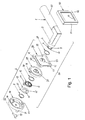
- FIGS. 1 and 6 an inventive door or window fitting is evident, which can be mounted on one side of a door leaf 17 or window frame.
- a corresponding door or window fitting is arranged, with which the in FIG. 1 screwed fitting shown bolted can be.
- the in the FIGS. 1 and 2 illustrated door or window fitting comprises a handle 1 in the form of a pusher and a rosette 2, which can be screwed to the door leaf or window frame or on an opposite, not shown rosette.
- the handle 1 is rotatably mounted in the rosette 2 and fixed axially thereto.
- the substantially L-shaped handle 1 has a neck portion 3, at the free end of a guide lug or bearing portion 4 is provided.
- the bearing section 4 serves for the rotatable mounting of the handle 1 in the rosette 2 and is accordingly cylindrical.
- the diameter of the bearing portion 4 is smaller than that of the adjacent part of the neck portion 3, so that in the transition region, a diameter stage 5 is present.
- the bearing portion 4 has a circumferential groove 6 into which a securing ring 7 can be inserted.
- a securing ring 7 In the interior of the neck portion 3 in the usual way an axially extending square hole 8 for rotatably receiving a square pin 9 (FIG. Figures 2 and 6 ) is provided, which cooperates with a lock.
- the bearing portion 4 further comprises two diametrically opposed axial slots 10, which, starting from the free end of the bearing portion 4, at least over the majority of the Length of the bearing section 4 extend. These axial slots are, as will be explained in more detail later, on the one hand for fixing an inner end portion 11 of a retaining spring 12 and on the other hand for rotationally fixed fixing a Drehanschlagelements 13 on the bearing section. 4
- the rosette 2 also has a plate-shaped mounting base 14, which in the present embodiment has the shape of a circular plate.
- a central, circular opening 15 serves to pass through the square pin 9 and also makes it possible that the free end portion of the bearing portion 4 in the mounted state of the fitting can still slightly protrude into the opening 15.
- the mounting base 14 is by means of two screws 16 on the door leaf 17 ( Figures 2 and 6 ) or window frame screwed.
- the mounting base 14 has two opposite screw holes 18, 19, wherein the screw hole 18 is provided with a through hole, so that a fixing screw 16 can be inserted therethrough, while the screw hole 19 has an internal thread, so that one of the opposite Side introduced fixing screw 16 can be screwed in the screw hole 19.
- the screw holes 18, 19 penetrate cylindrical pins 20, 21, which protrude in the axial direction from the rear of the mounting base 14 to the rear, that is in the direction of the door leaf 17 or window frame, and can be inserted into correspondingly sized through holes of the door leaf 17 and the window frame.
- the cylindrical pins 20, 21 thus simultaneously act as anti-rotation elements with which the mounting base 14 can be fixed against rotation on the door leaf 17 or window frame.
- the mounting base 14 has an end wall 22 which can be brought to the door leaf 17 or window frame to the plant, and a peripheral wall 23 which projects axially beyond the end wall 22. From the peripheral wall 23, two diametrically opposed radial projections 24 extend radially inwardly, which are part of a bayonet-type locking mechanism, which cooperates with a bearing plate 29.
- the radial projections 24 have a predetermined axial distance from the end wall 22.
- In the end wall 22 are further provided axially aligned with the radial projections 24 recesses 25 whose length is slightly larger than that of the radial projections 24th
- anti-rotation element 58 In a recess of the end wall 22 of the mounting base 14 designed as an insert anti-rotation element 58 is inserted.
- This anti-rotation element 58 has a securing tongue 59, which extends radially beyond the peripheral wall 23 from a section 60 arranged in the circumferential direction of the mounting base 14.
- the anti-rotation element 58 is thus formed substantially T-shaped, wherein the portion 60 circular arc runs.
- the anti-rotation element 58 can be made, for example, by being punched out of a flat plate.
- the recess in the end wall 22 of the mounting base 14, in which the anti-rotation element 58 is inserted has a depth that is suitably deep or only slightly deeper than the thickness of the anti-rotation element 58.
- the anti-rotation element 58 is automatically fixed captive on the mounting base 14 between the mounting base 14 and the door leaf 17 and window frame. Separate fastening means for the anti-rotation element 58 are therefore not required.
- the anti-rotation element 58 is, as will be explained in more detail later, for rotational locking of a blind ring 50, which is plugged onto a cap 28 at the end of fitting mounting.
- the mounting base 14 can, as out FIG. 6 can be screwed separately on the door leaf 17 or window frame and serves to hold a separately preassembled module 26, which, as from FIG. 1 3, in addition to the handle 1, the following elements are included: a sliding ring 27, the cover cap 28, the bearing disc 29 for rotatably supporting the handle 1, a sliding ring 30, the retaining spring 12, the rotation stop element 13 and the retaining ring 7. All the above elements can, before the assembly 26 is mounted on the mounting base 14, mounted in advance on the bearing portion 4 of the handle 1 and fixed there axially immovable, wherein they are to an axial direction are determined by the diameter step 5 and the other axial direction through the locking ring 7.
- the bearing disk 29 has an end wall 31 and a peripheral wall 32 protruding therefrom in the axial direction.
- a central passage opening 33 which is provided in the end wall 31, serves for passing and for rotatably supporting the bearing portion 4 of the handle 1.
- a pin-shaped rotation stop 34 extends axially to the rear, with a further rotation stop 35 of Drehanschlagelements 13 cooperates.
- two diametrically opposed locking tongues 36 are provided, which extend in the circumferential direction and adjacent to adjacent axial recesses 37, which are introduced from the outside into the peripheral wall 32.
- the locking tongues 36 and axial recesses 37 belong to the already mentioned bayonet-type locking mechanism, with which the bearing plate 29 can be fastened to the mounting base 14.
- the bearing plate 29 further in its immediately adjacent to the passage opening 33 edge region three axial projections 38 which are arranged distributed regularly over the circumference of the passage opening 33 and accordingly spaced from each other.
- the height of the axial projections 38 corresponds at least substantially to the thickness of the material of which the cover cap 28 consists.
- the axial projections 38 serve for rotational locking of the cap 28 when the bearing plate 29 and the cap 28 are arranged directly next to each other.
- the outer diameter of the bearing plate 29 is only slightly smaller than the inner diameter of the mounting base 14 in the region of the peripheral wall 23, so that the bearing plate 29 can be inserted with little radial play in the mounting base 14 and then rotated so that the locking tongues 36 of the bearing plate 29th engage behind the radial projections 24 of the bearing base 14, whereby the bearing plate 29 is locked to the mounting base 14 like a bayonet.
- the cap 28 has an end wall 39 with a central passage opening 40.
- the central passage opening 40 in turn serves to pass the bearing portion 4 of the handle 1.
- 40 radially projecting recesses 42 are provided in the edge region of the through hole, which are adapted to the shape of the projections 38 of the bearing plate 29, so that the projections 38 positively in the recesses 42 engage and can cause the aforementioned rotation lock when the bearing plate 29 and cap 28 are directly adjacent to each other.
- the number and shape of the projections 38 and recesses 42 may vary widely.
- the cap 28 has such a depth T, that in the finished assembled state of the door or window fitting a distance A to the door leaf 17 or window frame Has.
- the inner edge 48 of the shoulder portions 41 which project furthest in the direction of the door leaf 17 or window frame, have a distance A to the door leaf 17 or window frame.
- This distance A causes that during a rotary movement of the cap 28 for bayonet-like locking of the bearing plate 29 on the mounting base 14, the cap 28 does not come into contact with the door leaf 17 or window frame, thereby scratching is avoided.
- the shoulder sections 41 are isolated, circumferentially distributed shoulder sections. This means that the individual shoulder portions 41 are separated by gaps 49 in the circumferential direction. Alternatively, however, the intermediate spaces 49 can also be omitted, so that a peripheral peripheral wall is formed, which extends in the same manner as the shoulder portions 41 from the end wall 39 in the direction of the door leaf 17 or window frame.
- the shoulder portions 41 are used for attaching and clamping the blind ring 50, which is adapted to the outer contour of the cap 28 and is accordingly designed as a square Aufsteckrahmen.
- the blend ring 50 has an L-shaped cross-sectional profile.
- the depth of the bezel 50 ie the depth of its peripheral wall 51, is greater than the depth T of the cap 28 and dimensioned such that the peripheral wall 51 of the bezel 50 in the direction of the door leaf 17 or window frame not only the cap 28, but also the Covered by the gap A gap when the aperture ring 50 on the shoulder portions 41 of the cap 28 is attached.
- the frame-shaped circumferential wall 52 of the aperture ring 50 is located on the slightly recessed edge region 53 (FIG. FIG. 1 ) of the end wall 39 of the cap 28 at.
- FIG. 5 is further seen that in the peripheral wall 51 of the diaphragm 50, a recess 54 is provided.
- the securing tines 59 of the fixed to the mounting base 14 anti-rotation element 58 engages with little lateral play or play, when the aperture ring 50 is attached to the cap 28. Due to the interaction of recess 54 and locking tongue 59, therefore, a twist lock is provided which prevents rotation of the bezel 50 together with the cap 28 relative to the mounting base 14 with fitting mounted, as long as the bezel 50 is in the mounted end position. As a result, scratching the door leaf or window frame surface is prevented.
- the recess 54 serves for insertion of a tool, such as screwdriver, when the blind ring 50 is to be removed from the cap 28 again.
- the hold-up spring 12 consists of a leaf spring with a plurality of superposed windings, which enclose a central passage opening 43.
- the passage opening 43 is dimensioned so that the bearing portion 4 of the handle 1 can be inserted therethrough.
- the inner end portion 11 of the hold-up spring 12 is bent radially inwardly and is radially after inside, that it can be inserted in one of the axial slots 10 of the bearing portion 4.
- the retaining spring 12 is fixed with its inner end portion 11 on the bearing section 4.
- the outer end portion 44 of the retaining spring 11, however, is bent outwardly, whereby a hook is formed, with which the retaining spring 12 can be suspended on the rotation stop 34 with bias.
- the biasing force of the hold-up spring 12 therefore acts in the in FIG. 1 shown embodiment such that the handle 1 is urged counterclockwise in the illustrated horizontal starting position.
- the illustrated Dregehgangsposition the handle 1 is determined by the rotation stopper 13, which is formed in the illustrated embodiment as an annular disc.
- the rotation stop element 13 has a central passage opening 45. This is dimensioned so that the rotational stop element 13 can be plugged onto the bearing portion 4 of the handle 1.
- Two inwardly projecting radial projections 46 engage in the axial slots 10 of the bearing portion 4, whereby the rotational stop member 13 is rotatably connected to the handle 1.
- the rotational stop 35 of the Drehanschlagelements 13 consists of a radially outwardly projecting nose which abuts under the action of the retaining spring 12 in the rotational output position of the handle 1 on the pin-like rotation stop 34 of the bearing plate 29.
- the mounting base 14 is initially screwed by means of the screws 16 on the door leaf 17 or window frame. Subsequently, the preassembled module 26 is approximated to the mounting base 14 in the axial direction.
- the handle 1 is located in the rotational output position, that is, the grip part 47 is arranged horizontally. In this position, the square hole 8 is aligned in the neck portion 3 such that the square pin 9 can be inserted into the square hole 8.
- the bearing plate 29 is in the immediate vicinity of the mounting base 14, the cap 28 is engaged with the fingers and rotated by a certain angular amount, which may be 25 degrees, for example, against the biasing force of the retaining spring 12 in the counterclockwise direction (arrow 57). Since the bearing plate 29 is rotatably connected to the cap 28, the bearing plate 29 is rotated accordingly. This rotation causes the provided on the outer circumference of the bearing plate 29 axial recesses 37 are aligned with the radial projections 24 of the mounting base 14, whereby the bearing plate 29 can be pushed completely in the axial direction on the mounting base 14. In the fully pushed state, the bearing plate 29 is located substantially within the mounting base 14, while the cap 28 partially covers the mounting base 14. The peripheral wall 23 of the mounting base 14 thus extends into a space between the bearing plate 29 and the shoulder portions 41 of the cap 28th
Landscapes
- Engineering & Computer Science (AREA)
- Mechanical Engineering (AREA)
- Hinges (AREA)
Abstract
Description
- Die Erfindung betrifft einen Tür- oder Fensterbeschlag gemäß dem Oberbegriff des Anspruches 1.
- Tür- oder Fensterbeschläge, die einen Montagesockel aufweisen, der zunächst getrennt von der Handhabe am Türblatt oder am Fensterrahmen festgeschraubt werden kann, sind beispielsweise aus der
DE 200118006 U1 bekannt. Bei diesem bekannten Beschlag kann die Handhabe mit einem bajonettartigen Verriegelungsmechanismus, der sich an einer an der Handhabe festgelegten Lagerbuchse befindet, am Montage-sockel befestigt werden. Die Festlegung der Handhabe im Montagesockel erfolgt mittels eines drehbaren Verriegelungselementes, das zwischen dem Ober- und Unterteil des Montagesockels angeordnet ist und bajonettartige Vorsprünge aufweist. Mittels eines Spezialwerkzeuges kann dieses Verriegelungselement zwischen einer Verriegelungs- und Entriegelungsposition gedreht werden. Zum Abdecken des Montagesockels wird die Abdeckkappe axial auf dem Hals der Handhabe verschoben und in ihrem äußeren Umfangsbereich in entsprechende Radialvorsprünge des Montagesockels eingeclipst. Dieser bekannte Beschlag ist relativ kompliziert aufgebaut und erfordert zur Montage und Demontage ein Spezialwerkzeug. - Ferner ist aus der
EP 2 182 144 A1 ein Tür- oder Fensterbeschlag gemäß dem Oberbegriff des Anspruches 1 bekannt, der bereits wesentlich einfacher aufgebaut ist sowie eine einfachere und schnellere Montage und Demontage ermöglicht. Bei diesem bekannten Tür- oder Fensterbeschlag wirkt der bajonettartige Verriegelungsmechanismus direkt zwischen Montagesockel und einer Lagerscheibe für die Handhabe, die an der Handhabe vormontiert ist. Eine äußere Abdeckkappe ist drehfest mit der Lagerscheibe verbunden. die Abdeckkappe wird mit der Hand ergriffen und zusammen mit der Lagerscheibe in eine bestimmte Winkelstellung relativ zum Montagesockel gedreht, wodurch Lagerscheibe und Montagesockel zusammengesteckt und relativ zueinander bajonettartig verriegelt werden können. Das Drehen in die Verriegelungsstellung erfolgt dabei durch eine Hochhaltefeder, durch welche die Handhabe relativ zur Lagerscheibe in eine vorbestimmte Drehausgangsposition vorgespannt ist. Das Drehen in die Entriegelungsstellung erfolgt manuell entgegen der Vorspannkraft der Hochhaltefeder durch Drehen der Abdeckkappe in die entgegengesetzte Richtung. - Bei diesem bekannten Beschlag kann es vorkommen, dass das Türblatt oder der Fensterrahmen beim Drehen der Abdeckkappe verkratzt wird, da im fertig montierten Zustand des Beschlags der innere Rand der Abdeckkappe, d.h. der dem Türblatt oder dem Fensterrahmen zugewandte Rand, am Türblatt bzw. Fensterrahmen anliegt. Dies ist insbesondere dann von Nachteil, wenn es sich nicht um eine runde, sondern um eine eckige Rosette handelt, da dann die Kratzspuren sichtbar sein können.
- Der Erfindung liegt von daher die Aufgabe zu Grunde, einen Tür- oder Fensterbeschlag der eingangs genannten Art zu schaffen, der eine Beschädigung des Türblatts oder Fensterrahmens durch die Abdeckkappe zuverlässig ausschließt.
- Diese Aufgabe wird erfindungsgemäß durch einen Fenster- oder Türbeschlag mit den Merkmalen des Anspruches 1 gelöst. Vorteilhafte Ausführungsformen der Erfindung sind in den weiteren Ansprüchen beschrieben.
- Beim erfindungsgemäßen Tür- oder Fensterbeschlag hat die Abdeckkappe eine derartige Tiefe, dass sie im fertig montierten Zustand des Tür- oder Fensterbeschlags einen Abstand zum Türblatt oder Fensterrahmen hat. Weiterhin umfasst die Abdeckblende einen auf der Abdeckkappe anordenbaren und an dieser befestigbaren Blendring, der den durch den Abstand gebildeten Spalt abdeckt.
- Dadurch, dass die Abdeckkappe im fertig montierten Zustand einen Abstand zum Türblatt oder Fensterrahmen hat, gerät die Abdeckkappe bei der Montage nicht in Kontakt mit dem Türblatt oder Fensterrahmen. Ein Verkratzen des Türblatts bzw. Fensterrahmens beim Drehen der Abdeckkappe wird daher vermieden. Der durch den Abstand gebildete Spalt bzw. Zwischenraum zwischen der Abdeckkappe und dem Türblatt bzw. Fensterrahmen wird dagegen durch den zusätzlichen Blendring überbrückt und abgedeckt, der zweckmäßigerweise auf die Abdeckkappe aufgesteckt wird, bis dessen innerer Rand am Türblatt bzw. Fensterrahmen anliegt. Mit der erfindungsgemäßen zweiteiligen Abdeckblende sind damit keinerlei optische Einbußen verbunden. Die Zweiteilung der Abdeckblende in innerer Abdeckkappe und äußeren Blendring bietet sogar die Möglichkeit, Beschlagdesigns in optisch besonders ansprechender Weise zu variieren, da Abdeckkappe und Blendring mit unterschiedlichen Oberflächenbeschaffenheiten, Farben und/oder Materialien hergestellt werden können.
- Gemäß einer besonders vorteilhaften Ausführungsform ist der Blendring als auf die Abdeckkappe aufsteckbarer Aufsteckrahmen ausgebildet. Dieser Aufsteckrahmen kann so gestaltet sein, dass er die Abdeckkappe nur in einem relativ schmalen äußeren Randbereich sowie am Umfang übergreift. Es ist jedoch auch möglich, den Blendring relativ nahe bis zum Halsabschnitt der Handhabe heranzuführen.
- Vorteilhafterweise weist die Abdeckkappe vereinzelte, in Umfangsrichtung verteilte und radial vorstehende Schulterabschnitte auf, auf welche der Blendring aufsteckbar ist. Hierdurch kann einerseits die Abdeckkappe materialsparend gefertigt und andererseits der Blendring auf einfache Weise auf die Abdeckkappe aufgesteckt und gegebenenfalls auch wieder abgenommen werden.
- Vorteilhafterweise haben die Abdeckkappe und der Blendring eine viereckige Form, wobei die vorstehenden Schulterabschnitte in den Eckenbereichen der Abdeckkappe angeordnet sind. Hierdurch wird der Blendring bei der Montage zwangsläufig in der richtigen Winkelausrichtung relativ zur Abdeckkappe auf diese aufgesteckt. Außerdem ergibt sich ein sicherer Sitz des Blendrings auf der Abdeckkappe. Vorteilhafterweise ist am Montagesockel ein Drehsicherungselement zur Verhinderung einer Drehbewegung des Blendrings relativ zum Montagesockel vorgesehen. Hierdurch kann ein ungewolltes Verdrehen des auf die Abdeckkappe aufgesteckten Blendrings relativ zum Montagesockel bzw. zum Türblatt oder Fensterrahmen verhindert werden, wodurch ein Verkratzen der Türblatt- oder Fensterrahmenoberfläche vermieden werden kann.
- Vorteilhafterweise umfasst das Drehsicherungselement eine radial über die Umfangswand des Montagesockels vorragende Sicherungszunge, die mit einer Aussparung des Blendrings zusammenwirkt. Hierdurch kann auf besonders einfache und kostengünstige Weise die gewünschte Drehsicherung realisiert werden.
- Vorteilhafterweise ist das Drehsicherungselement als Einlageteil ausgebildet, das in eine Vertiefung in der Stirnwand des Montagesockels formschlüssig einlegbar ist. Hierdurch ist die Montage des Drehsicherungselements am Montagesockel auf besonders einfache und schnelle Weise möglich, da separate Befestigungsmittel zur Befestigung des Drehsicherungselements am Montagesockel nicht erforderlich sind.
- Die Erfindung wird nachfolgend anhand der Zeichnungen beispielhaft näher erläutert. Es zeigen:
- Figur 1:
- eine Explosionsdarstellung des erfindungs-gemäßen Tür- oder Fensterbeschlags,
- Figur 2:
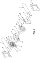
- eine Explosionsdarstellung von zwei Tür-oder Fensterbeschlägen, die auf gegenüber-liegenden Seiten eines Türblatts oder Fensterrahmens befestigt werden können,
- Figuren 3a, 3b:
- räumliche Darstellungen des Montagesockels von der hinteren und der vorderen Seite her,
- Figuren 4a, 4b:
- räumliche Darstellungen der Lagerscheibe von der hinteren und vorderen Seite her,
- Figur 5:
- eine räumliche Darstellung der Abdeckkappe und des Blendrings von der hinteren Seite her,
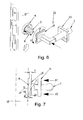
- Figur 6:
- eine Darstellung des Tür- oder Fenster-beschlags bei der Montage, wobei der Montagesockel bereits an einem Türblatt befestigt ist, und
- Figur 7:
- eine Seitenansicht des Tür- oder Fenster-beschlags beim Aufstecken des Blendrings auf die Abdeckkappe.
- Aus den
Figuren 1 und6 ist ein erfindungsgemäßer Tür- oder Fensterbeschlag ersichtlich, der an einer Seite eines Türblatts 17 oder Fensterrahmens montiert werden kann. Auf der gegenüberliegenden Seite des Türblatts 17 oder Fensterrahmens wird, wie ausFigur 2 ersichtlich, in der Regel ein entsprechender Tür- oder Fensterbeschlag angeordnet, mit dem der inFigur 1 dargestellte Beschlag verschraubt werden kann. Alternativ ist es jedoch auch ohne weiteres möglich, auf der gegenüberliegenden Seite einen anderen Beschlag dieser Art oder auch nur eine Rosette anzubringen, mit der der dargestellte Beschlag verschraubt werden kann. - Der in den
Figuren 1 und2 dargestellte Tür- oder Fensterbeschlag umfasst eine Handhabe 1 in der Form eines Drückers und eine Rosette 2, die am Türblatt oder Fensterrahmen beziehungsweise an einer gegenüberliegenden, nicht dargestellten Rosette festgeschraubt werden kann. Die Handhabe 1 ist drehbar in der Rosette 2 gelagert und axial an dieser festgelegt. - Die im Wesentlichen L-förmige Handhabe 1 weist einen Halsabschnitt 3 auf, an dessen freiem Ende ein Führungsansatz oder Lagerabschnitt 4 vorgesehen ist. Der Lagerabschnitt 4 dient zur drehbaren Lagerung der Handhabe 1 in der Rosette 2 und ist dementsprechend zylinderförmig ausgebildet. Der Durchmesser des Lagerabschnittes 4 ist kleiner als derjenige des angrenzenden Teils des Halsabschnittes 3, so dass im Übergangsbereich eine Durchmesserstufe 5 vorhanden ist.
- Weiterhin weist der Lagerabschnitt 4 eine Umfangsnut 6 auf, in die ein Sicherungsring 7 eingesetzt werden kann. Im Inneren des Halsabschnittes 3 ist in üblicher Weise ein axial verlaufendes Vierkantloch 8 zur drehfesten Aufnahme eines Vierkantstifts 9 (
Figuren 2 und6 ) vorgesehen, der mit einem Schloss zusammenwirkt. Der Lagerabschnitt 4 weist ferner zwei diametral gegenüberliegende Axialschlitze 10 auf, die sich, ausgehend vom freien Ende des Lagerabschnittes 4, zumindest über den überwiegenden Teil der Länge des Lagerabschnittes 4 erstrecken. Diese Axialschlitze dienen, wie später noch näher erläutert wird, einerseits zum Festlegen eines inneren Endbereichs 11 einer Hochhaltefeder 12 und anderseits zum drehfesten Festlegen eines Drehanschlagelements 13 am Lagerabschnitt 4. - Die Rosette 2 weist weiterhin einen plattenförmigen Montagesockel 14 auf, der im vorliegenden Ausführungsbeispiel die Form einer Kreisplatte hat. Eine zentrale, kreisförmige Öffnung 15 dient zum Hindurchführen des Vierkantstifts 9 und ermöglicht es außerdem, dass der freie Endbereich des Lagerabschnittes 4 im montierten Zustand des Beschlags noch geringfügig in die Öffnung 15 hineinragen kann.
- Der Montagesockel 14 wird mittels zweier Befestigungsschrauben 16 am Türblatt 17 (
Figuren 2 und6 ) beziehungsweise Fensterrahmen festgeschraubt. Eine der Befestigungsschrauben 16 wird, wie ausFigur 2 ersichtlich, von einer Seite des dargestellten Beschlags durch den Montagesockel 14 hindurchgeführt und mit dem auf der gegenüberliegenden Seite des Türblatts 17 oder des Fensterrahmens angeordneten Montagesockel 14 verschraubt, während die andere Befestigungsschraube von der anderen Seite her eingeschraubt wird. Zu diesem Zweck weist der Montage-sockel 14 zwei gegenüberliegende Schraubenlöcher 18, 19 auf, wobei das Schraubenloch 18 mit einer Durchgangsbohrung versehen ist, so dass eine Befestigungsschraube 16 hindurchgesteckt werden kann, während das Schraubenloch 19 ein Innengewinde aufweist, so dass eine von der gegenüberliegenden Seite her eingeführte Befestigungsschraube 16 im Schraubenloch 19 festgeschraubt werden kann. - Die Schraubenlöcher 18, 19 durchdringen Zylinderzapfen 20, 21, die in axialer Richtung von der Rückseite des Montagesockels 14 nach hinten, das heißt in Richtung des Türblatts 17 beziehungsweise Fensterrahmens, vorstehen und in entsprechend dimensionierte Durchgangslöcher des Türblatts 17 beziehungsweise des Fensterrahmens eingesteckt werden können. Die Zylinderzapfen 20, 21 wirken damit gleichzeitig als Drehsicherungselemente, mit denen der Montagesockel 14 drehfest am Türblatt 17 beziehungsweise Fensterrahmen festgelegt werden kann.
- Wie aus den
Figuren 3a, 3b ersichtlich, weist der Montagesockel 14 eine Stirnwand 22 auf, die am Türblatt 17 beziehungsweise Fensterrahmen zur Anlage gebracht werden kann, sowie eine Umfangswand 23, die über die Stirnwand 22 axial vorsteht. Von der Umfangswand 23 erstrecken sich zwei diametral gegenüberliegende Radialvorsprünge 24 radial nach innen, die Teil eines bajonettartigen Verriegelungsmechanismus sind, der mit einer Lagerscheibe 29 zusammenwirkt. Die Radialvorsprünge 24 haben einen vorbestimmten axialen Abstand zur Stirnwand 22. In der Stirnwand 22 sind weiterhin axial fluchtend zu den Radialvorsprüngen 24 Ausnehmungen 25 vorgesehen, deren Länge etwas größer ist als diejenige der Radialvorsprünge 24. - In eine Vertiefung der Stirnwand 22 des Montagesockels 14 ist ein als Einlegeelement ausgebildetes Drehsicherungselement 58 eingelegt. Dieses Drehsicherungselement 58 weist eine Sicherungszunge 59 auf, die sich von einem in Umfangsrichtung des Montagesockels 14 angeordneten Abschnitt 60 radial über die Umfangswand 23 hinaus erstreckt. Das Drehsicherungselement 58 ist damit im Wesentlichen T-förmig ausgebildet, wobei der Abschnitt 60 kreisbogenförmig verläuft. Das Drehsicherungselement 58 kann beispielsweise dadurch hergestellt werden, dass es aus einer ebenen Platte ausgestanzt wird. Die Vertiefung in der Stirnwand 22 des Montagesockels 14, in welcher das Drehsicherungselement 58 eingelegt ist, hat eine Tiefe, die zweckmäßigerweise gleich tief oder nur geringfügig tiefer ist als die Dicke des Drehsicherungselements 58. Liegt der Montagesockel 14 mit seiner Stirnwand 22 am Türblatt 17 bzw. Fensterrahmen an, ist das Drehsicherungselement 58 automatisch zwischen dem Montagesockel 14 und dem Türblatt 17 bzw. Fensterrahmen unverlierbar am Montagesockel 14 festgelegt. Separate Befestigungsmittel für das Drehsicherungselement 58 sind daher nicht erforderlich.
- Das Drehsicherungselement 58 dient, wie später noch näher erläutert wird, zur Drehverriegelung eines Blendrings 50, der am Ende der Beschlagmontage auf eine Abdeckkappe 28 aufgesteckt wird.
- Der Montagesockel 14 kann, wie aus
Figur 6 ersichtlich, separat am Türblatt 17 beziehungsweise Fensterrahmen festgeschraubt werden und dient zur Halterung einer separat vormontierbaren Baugruppe 26, die, wie ausFigur 1 ersichtlich, zusätzlich zur Handhabe 1 die folgenden Elemente umfasst: einen Gleitring 27, die Abdeckkappe 28, die Lagerscheibe 29 zur drehbaren Lagerung der Handhabe 1, einen Gleitring 30, die Hochhaltefeder 12, das Drehanschlagelement 13 sowie den Sicherungsring 7. Sämtliche vorgenannten Elemente können, bevor die Baugruppe 26 am Montagesockel 14 befestigt wird, vorab auf dem Lagerabschnitt 4 der Handhabe 1 montiert und dort axial unverschiebbar festgelegt werden, wobei sie zur einen Axialrichtung hin durch die Durchmesserstufe 5 und zur anderen Axialrichtung hin durch den Sicherungsring 7 festgelegt sind. - Anhand der
Figuren 4a, 4b wird im Folgenden die Lagerscheibe 29 näher beschrieben. Die Lagerscheibe 29 weist eine Stirnwand 31 und eine von dieser in Axialrichtung vorstehende Umfangswand 32 auf. Eine mittige Durchgangsöffnung 33, die in der Stirnwand 31 vorgesehen ist, dient zum Hindurchführen und zum drehbaren Lagern des Lagerabschnitts 4 der Handhabe 1. Von der Rückseite der Stirnwand 31 erstreckt sich ein zapfenförmiger Drehanschlag 34 axial nach hinten, der mit einem weiteren Drehanschlag 35 des Drehanschlagelements 13 zusammenwirkt. An der Außenseite der Umfangswand 32 sind zwei diametral gegenüberliegende Verriegelungszungen 36 vorgesehen, die sich in Umfangsrichtung erstrecken und an benachbarte Axialaussparungen 37 angrenzen, die von außen her in die Umfangswand 32 eingebracht sind. Die Verriegelungszungen 36 und Axialaussparungen 37 gehören zu dem bereits erwähnten bajonettartigen Verriegelungsmechanismus, mit dem die Lagerscheibe 29 am Montagesockel 14 befestigbar ist. - Wie insbesondere aus
Figur 4b ersichtlich, weist die Lagerscheibe 29 weiterhin in ihrem an die Durchgangsöffnung 33 unmittelbar angrenzenden Randbereich drei axiale Vorsprünge 38 auf, die über den Umfang der Durchgangsöffnung 33 regelmäßig verteilt angeordnet und dementsprechend zueinander beabstandet sind. Die Höhe der axialen Vorsprünge 38 entspricht zumindest im Wesentlichen der Dicke des Materials, aus dem die Abdeckkappe 28 besteht. Die axialen Vorsprünge 38 dienen zur Drehverriegelung der Abdeckkappe 28, wenn die Lagerscheibe 29 und die Abdeckkappe 28 unmittelbar nebeneinander angeordnet werden. Weiterhin ist der Außendurchmesser der Lagerscheibe 29 nur geringfügig kleiner als der Innendurchmesser des Montagesockels 14 im Bereich der Umfangswand 23, so dass die Lagerscheibe 29 mit geringem radialen Spiel in den Montagesockel 14 eingeführt und anschließend derart verdreht werden kann, dass die Verriegelungszungen 36 der Lagerscheibe 29 die Radialvorsprünge 24 des Lagersockels 14 hintergreifen, wodurch die Lagerscheibe 29 mit dem Montagesockel 14 bajonettartig verriegelt wird. - Die Abdeckkappe 28 weist eine Stirnwand 39 mit einer mittigen Durchgangsöffnung 40 auf. Die mittige Durchgangsöffnung 40 dient wiederum zum Hindurchführen des Lagerabschnitts 4 der Handhabe 1. Weiterhin sind im Randbereich der Durchgangsöffnung 40 radial vorspringende Ausnehmungen 42 vorgesehen, die an die Form der Vorsprünge 38 der Lagerscheibe 29 angepasst sind, so dass die Vorsprünge 38 formschlüssig in die Ausnehmungen 42 eingreifen und die bereits erwähnte Drehverriegelung bewirken können, wenn die Lagerscheibe 29 und Abdeckkappe 28 direkt aneinander liegen. Anzahl und Form der Vorsprünge 38 und Ausnehmungen 42 können in weitem Umfang variieren.
- In den vier Eckenbereichen der viereckigen Abdeckkappe 28 sind um die Ecken herumgezogene Schulterabschnitte 41 vorgesehen, die in Richtung Türblatt 17 bzw. Fensterrahmen axial über die Stirnwand 39 vorstehen und auch seitlich, d.h. in radialer Richtung, geringfügig über den äußeren Rand der Stirnwand 39 vorstehen. Wie aus
Figur 7 ersichtlich, hat die Abdeckkappe 28 eine derartige Tiefe T, dass sie im fertig montierten Zustand des Tür- oder Fensterbeschlags einen Abstand A zum Türblatt 17 oder Fensterrahmen hat. Dies bedeutet mit anderen Worten, dass bei dem dargestellten Ausführungsbeispiel der innere Rand 48 der Schulterabschnitte 41, die am weitesten in Richtung Türblatt 17 bzw. Fensterrahmen vorragen, einen Abstand A zum Türblatt 17 bzw. Fensterrahmen haben. Dieser Abstand A bewirkt, dass bei einer Drehbewegung der Abdeckkappe 28 zum bajonettartigen Verriegeln der Lagerscheibe 29 am Montagesockel 14 die Abdeckkappe 28 mit dem Türblatt 17 bzw. Fensterrahmen nicht in Kontakt gelangt, wodurch ein Verkratzen vermieden wird. - Bei den Schulterabschnitten 41 handelt es sich im gezeigten Ausführungsbeispiel um vereinzelte, in Umfangsrichtung verteilte Schulterabschnitte. Dies bedeutet, dass die einzelnen Schulterabschnitte 41 in Umfangsrichtung durch Zwischenräume 49 miteinander getrennt sind. Alternativ können die Zwischenräume 49 jedoch auch weggelassen werden, so dass eine umlaufende Umfangswand gebildet wird, die sich in gleicher Weise wie die Schulterabschnitte 41 von der Stirnwand 39 in Richtung Türblatt 17 bzw. Fensterrahmen erstreckt.
- Die Schulterabschnitte 41 dienen zum Aufstecken und Festklammern des Blendrings 50, der an die Außenkontur der Abdeckkappe 28 angepasst und dementsprechend als viereckiger Aufsteckrahmen ausgebildet ist. Der Blendring 50 hat ein L-förmiges Querschnittsprofil. Die Tiefe des Blendrings 50, d.h. die Tiefe seiner Umfangswand 51, ist größer als die Tiefe T der Abdeckkappe 28 und derart bemessen, dass die Umfangswand 51 des Blendrings 50 in Richtung des Türblatts 17 bzw. Fensterrahmens nicht nur die Abdeckkappe 28, sondern auch den durch den Abstand A gebildeten Spalt überdeckt, wenn der Blendring 50 auf die Schulterabschnitte 41 der Abdeckkappe 28 aufgesteckt ist. Im aufgesteckten Zustand liegt die rahmenförmig umlaufende Wand 52 des Blendrings 50 am etwas zurückversetzten Randbereich 53 (
Figur 1 ) der Stirnwand 39 der Abdeckkappe 28 an. - Abdeckklappe 28 und Blendring 50 bilden zusammen eine zweiteilige Abdeckblende 56 (
Figur 5 ). - Aus
Figur 5 ist weiter erkennbar, dass in der Umfangswand 51 des Blendrings 50 eine Aussparung 54 vorgesehen ist. In diese Aussparung 54 greift die Sicherungszuge 59 des am Montagesockel 14 festgelegten Drehsicherungselements 58 mit nur geringem seitlichen Spiel oder spielfrei ein, wenn der Blendring 50 auf die Abdeckkappe 28 aufgesteckt ist. Durch das Zusammenwirken von Aussparung 54 und Sicherungszunge 59 wird daher eine Drehverriegelung geschaffen, die ein Verdrehen des Blendrings 50 zusammen mit der Abdeckkappe 28 relativ zum Montagesockel 14 bei montiertem Beschlag verhindert, so lange sich der Blendring 50 in der aufgesteckten Endposition befindet. Hierdurch wird ein Verkratzen der Türblatt- bzw. Fensterrahmenoberfläche verhindert. Weiterhin dient die Aussparung 54 zum Einführen eines Werkzeugs, beispielsweise Schraubenziehers, wenn der Blendring 50 wieder von der Abdeckkappe 28 abgezogen werden soll. - Wie aus
Figur 1 ersichtlich, besteht die Hochhaltefeder 12 aus einer Blattfeder mit mehreren übereinandergeordneten Windungen, die eine mittige Durchgangsöffnung 43 umschließen. Die Durchgangsöffnung 43 ist so bemessen, dass der Lagerabschnitt 4 der Handhabe 1 hindurchgesteckt werden kann. Der innere Endbereich 11 der Hochhaltefeder 12 ist radial nach innen abgebogen und steht derart radial nach innen vor, dass er in einem der Axialschlitze 10 des Lagerabschnitts 4 eingeführt werden kann. Hierdurch ist die Hochhaltefeder 12 mit ihrem inneren Endbereich 11 am Lagerabschnitt 4 festgelegt. Der äußere Endbereich 44 der Hochhaltefeder 11 ist dagegen nach außen aufgebogen, wodurch ein Haken gebildet wird, mit dem die Hochhaltefeder 12 am Drehanschlag 34 mit Vorspannung eingehängt werden kann. Die Vorspannkraft der Hochhaltefeder 12 wirkt daher in dem inFigur 1 gezeigten Ausführungsbeispiel derart, dass die Handhabe 1 im Gegenuhrzeigersinn in die dargestellte, horizontale Ausgangslage gedrängt wird. - Die dargestellte Drehausgangsposition der Handhabe 1 wird durch das Drehanschlagelement 13 bestimmt, das im dargestellten Ausführungsbeispiel als Ringscheibe ausgebildet ist. Das Drehanschlagelement 13 weist eine mittige Durchgangsöffnung 45 auf. Diese ist so bemessen, dass das Drehanschlagelement 13 auf den Lagerabschnitt 4 der Handhabe 1 aufgesteckt werden kann. Zwei nach innen vorstehende Radialvorsprünge 46 greifen dabei in die Axialschlitze 10 des Lagerabschnitts 4 ein, wodurch das Drehanschlagelement 13 drehfest mit der Handhabe 1 verbunden ist. Der Drehanschlag 35 des Drehanschlagelements 13 besteht aus einer radial nach außen vorspringenden Nase, die unter der Wirkung der Hochhaltefeder 12 in der Drehausgangsposition der Handhabe 1 am zapfenartigen Drehanschlag 34 der Lagerscheibe 29 anschlägt.
- Mittels des Sicherungsrings 7 werden der Gleitring 27, die Abdeckkappe 28, die Lagerscheibe 29, der Gleitring 30, die Hochhaltefeder 12 und das Drehanschlagelement 13 (in dieser Reihenfolge) am Lagerabschnitt 4 axial unverschiebbar festgelegt.
- Im folgenden wird anhand der
Figuren 6 und 7 das Befestigen der Baugruppe 26 am Montagesockel 14 beschrieben. - Wie aus
Figur 6 ersichtlich, wird zunächst der Montage-sockel 14 mittels der Befestigungsschrauben 16 am Türblatt 17 beziehungsweise Fensterrahmen festgeschraubt. Anschließend wird die vormontierte Baugruppe 26 in axialer Richtung dem Montagesockel 14 angenähert. Die Handhabe 1 befindet sich dabei in der Drehausgangsposition, das heißt das Griffteil 47 ist horizontal angeordnet. In dieser Position ist das Vierkantloch 8 im Halsabschnitt 3 derart ausgerichtet, dass der Vierkantstift 9 in das Vierkantloch 8 eingeführt werden kann. - Befindet sich die Lagerscheibe 29 in unmittelbarer Nachbarschaft des Montagesockels 14, wird die Abdeckkappe 28 mit den Fingern ergriffen und um einen bestimmten Winkelbetrag, der beispielsweise 25 Grad betragen kann, gegen die Vorspannkraft der Hochhaltefeder 12 im Gegenuhrzeigersinn gedreht (Pfeil 57). Da die Lagerscheibe 29 drehfest mit der Abdeckkappe 28 verbunden ist, wird die Lagerscheibe 29 entsprechend mitgedreht. Diese Drehung bewirkt, dass die am Außenumfang der Lagerscheibe 29 vorgesehenen Axialaussparungen 37 mit den Radialvorsprüngen 24 des Montagesockels 14 fluchten, wodurch die Lagerscheibe 29 in axialer Richtung vollständig auf den Montagesockel 14 aufgeschoben werden kann. Im vollkommen aufgeschobenen Zustand befindet sich die Lagerscheibe 29 im Wesentlichen innerhalb des Montagesockels 14, während die Abdeckkappe 28 den Montagesockel 14 teilweise überdeckt. Die Umfangswand 23 des Montagesockels 14 erstreckt sich somit in einen Zwischenraum zwischen der Lagerscheibe 29 und den Schulterabschnitten 41 der Abdeckkappe 28.
- Wird anschließend die Abdeckkappe 28 losgelassen, wird die Lagerscheibe 29 zusammen mit der Abdeckkappe 28 durch die Vorspannkraft der Hochhaltefeder 12 im Uhrzeigersinn relativ zur Handhabe 1 in die in Figur 12 gezeigte Verriegelungsstellung zurückgedreht. In dieser Verriegelungsstellung hintergreifen die Verriegelungszungen 36 der Lagerscheibe 29 die Radialvorsprünge 24 des Montagesockels 14, wodurch die Baugruppe 26 am Montagesockel 14 festgelegt ist. Anschließend wird, wie in
Figur 7 durch die Pfeile 55 angedeutet, der Blendring 50 über die Handhabe 1 geschoben und auf die Abdeckkappe 28 aufgesteckt, wobei durch die Schulterabschnitte 41 eine derartige Klemmkraft auf den Blendring 50 ausgeübt wird, dass dieser ohne weitere Befestigungsmittel auf der Abdeckkappe 28 gehalten wird. Beim Aufsteckvorgang wird der Blendring 50 nicht mehr gedreht, so dass auch dann, wenn der innere Rand des Blendrings 50 gegen das Türblatt 17 bzw. den Fensterrahmen gedrückt wird, keine drehbedingten Kratzspuren hinterlassen werden.
Claims (7)
- Tür- oder Fensterbeschlag mit einer Handhabe (1) und einer Rosette (2), die einen an einem Türblatt (17) oder an einem Fensterrahmen befestigbaren Montagesockel (14), eine auf einem Lagerabschnitt (4) der Handhabe (1) axial festgelegte Lagerscheibe (29) zur drehbaren Lagerung der Handhabe (1) und eine Abdeckblende (56) aufweist, die den Montagesockel (14) und die Lagerscheibe (29) überdeckt und eine Abdeckkappe (28) umfasst, die drehfest mit der Lagerscheibe (29) gekoppelt ist, wobei der Montagesockel (14) getrennt von der Lagerscheibe (29) am Türblatt (17) oder Fensterrahmen befestigbar und die Lagerscheibe (29) mittels eines bajonettartigen Verriegelungsmechanismus durch Verdrehen am Montagesockel (14) festlegbar ist, dadurch gekennzeichnet, dass die Abdeckkappe (28) eine derartige Tiefe (T) hat, dass sie im fertig montierten Zustand des Tür- oder Fensterbeschlags einen Abstand (A) zum Türblatt (17) oder Fensterrahmen hat, und dass die Abdeckblende (56) einen auf der Abdeckkappe (28) anordenbaren und an dieser befestigbaren Blendring (50) umfasst, der den durch den Abstand (A) gebildeten Spalt abdeckt.
- Tür- oder Fensterbeschlag nach Anspruch 1, dadurch gekennzeichnet, dass der Blendring (50) als auf die Abdeckkappe (28) aufsteckbarer Aufsteckrahmen ausgebildet ist.
- Tür- oder Fensterbeschlag nach Anspruch 1 oder 2, dadurch gekennzeichnet, dass die Abdeckkappe (28) vereinzelte, in Umfangsrichtung verteilte und radial vorstehende Schulterabschnitte (41) aufweist, auf welche der Blendring (50) aufsteckbar ist.
- Tür- oder Fensterbeschlag nach Anspruch 3, dadurch gekennzeichnet, dass die Abdeckkappe (28) und der Blendring (50) eine viereckige Form haben und die vorstehenden Schulterabschnitte (41) in den Eckenbereichen der Abdeckkappe (28) angeordnet sind.
- Tür- oder Fensterbeschlag nach einem der vorhergehenden Ansprüche, dadurch gekennzeichnet, dass am Montagesockel (14) ein Drehsicherungselement (58) zur Verhinderung einer Drehbewegung des Blendrings (50) relativ zum Montagesockel (14) vorgesehen ist.
- Tür- oder Fensterbeschlag nach Anspruch 5, dadurch gekennzeichnet, dass das Drehsicherungselement (58) eine radial über die Umfangswand (23) des Montagesockels (14) vorragende Sicherungszunge (59) umfasst, die mit einer Aussparung (54) des Blendrings (50) zusammenwirkt.
- Tür- oder Fensterbeschlag nach Anspruch 5 oder 6, dadurch gekennzeichnet, dass das Drehsicherungselement (58) als Einlegeteil ausgebildet ist, das in eine Vertiefung in einer Stirnwand (22) des Montagesockels (14) formschlüssig einlegbar ist.
Priority Applications (1)
| Application Number | Priority Date | Filing Date | Title |
|---|---|---|---|
| EP13004156.9A EP2840203B1 (de) | 2013-08-22 | 2013-08-22 | Tür- oder Fensterbeschlag mit mehrteiliger Abdeckblende |
Applications Claiming Priority (1)
| Application Number | Priority Date | Filing Date | Title |
|---|---|---|---|
| EP13004156.9A EP2840203B1 (de) | 2013-08-22 | 2013-08-22 | Tür- oder Fensterbeschlag mit mehrteiliger Abdeckblende |
Publications (2)
| Publication Number | Publication Date |
|---|---|
| EP2840203A1 true EP2840203A1 (de) | 2015-02-25 |
| EP2840203B1 EP2840203B1 (de) | 2016-02-24 |
Family
ID=49033786
Family Applications (1)
| Application Number | Title | Priority Date | Filing Date |
|---|---|---|---|
| EP13004156.9A Active EP2840203B1 (de) | 2013-08-22 | 2013-08-22 | Tür- oder Fensterbeschlag mit mehrteiliger Abdeckblende |
Country Status (1)
| Country | Link |
|---|---|
| EP (1) | EP2840203B1 (de) |
Cited By (8)
| Publication number | Priority date | Publication date | Assignee | Title |
|---|---|---|---|---|
| US20180298635A1 (en) * | 2017-04-18 | 2018-10-18 | Taiwan Fu Hsing Industrial Co., Ltd. | Rebound apparatus for a lock assembly |
| US20190211580A1 (en) * | 2016-04-18 | 2019-07-11 | Kuriki Manufacture Co., Ltd | Locking structure for cover covering handle seat |
| DE102019200115A1 (de) * | 2019-01-08 | 2020-07-09 | Karcher Gmbh | Türschließsystem |
| WO2022031250A1 (en) | 2020-08-04 | 2022-02-10 | Guelesci Saffet | Smart assembly handle mechanism |
| EP4151819A1 (de) * | 2021-09-16 | 2023-03-22 | Dormakaba USA Inc. | Befestigungssystem für ein schliesssystem |
| EP4159957A1 (de) * | 2021-09-15 | 2023-04-05 | Karcher GmbH | Türschliesssystem |
| GB2628638A (en) * | 2023-03-31 | 2024-10-02 | Joseph Giles Ltd | Rose and handle |
| DE102023117406A1 (de) * | 2023-06-30 | 2025-01-02 | Huga Kg | Türflügel mit flächenbündigen Türbeschlag und Drückerhochhaltung und Montageverfahren |
Families Citing this family (1)
| Publication number | Priority date | Publication date | Assignee | Title |
|---|---|---|---|---|
| EP4124707A1 (de) * | 2021-07-28 | 2023-02-01 | Dormakaba Danmark | Türbeschlag und hochklappbares türverriegelungssystem |
Citations (7)
| Publication number | Priority date | Publication date | Assignee | Title |
|---|---|---|---|---|
| GB1069218A (en) * | 1965-04-06 | 1967-05-17 | Lilly & Sons Ltd B | Lever-handle door latch fittings |
| WO1992012314A1 (en) * | 1991-01-11 | 1992-07-23 | Whitco Pty. Ltd. | Handle assembly |
| US5732578A (en) * | 1995-02-24 | 1998-03-31 | Hyundai Metal Co., Ltd. | Device for maintaining the horizontality of a door lock lever |
| EP1882798A1 (de) * | 2006-07-27 | 2008-01-30 | ALMAR s.p.a. | Tür- oder Fensterbeschlag |
| EP2182144A1 (de) * | 2008-10-31 | 2010-05-05 | ALMAR s.p.a. | Tür- oder Fensterbeschlag |
| DE202011000933U1 (de) * | 2011-04-19 | 2011-08-10 | Franz Schneider Brakel Gmbh & Co. Kg | Drückerlagerung eines Tür- oder Fensterdrückers |
| WO2013050915A1 (en) * | 2011-10-04 | 2013-04-11 | MANITAL S.r.l. | Attachment rose and method of fitting a handle to a door or window fitting |
-
2013
- 2013-08-22 EP EP13004156.9A patent/EP2840203B1/de active Active
Patent Citations (7)
| Publication number | Priority date | Publication date | Assignee | Title |
|---|---|---|---|---|
| GB1069218A (en) * | 1965-04-06 | 1967-05-17 | Lilly & Sons Ltd B | Lever-handle door latch fittings |
| WO1992012314A1 (en) * | 1991-01-11 | 1992-07-23 | Whitco Pty. Ltd. | Handle assembly |
| US5732578A (en) * | 1995-02-24 | 1998-03-31 | Hyundai Metal Co., Ltd. | Device for maintaining the horizontality of a door lock lever |
| EP1882798A1 (de) * | 2006-07-27 | 2008-01-30 | ALMAR s.p.a. | Tür- oder Fensterbeschlag |
| EP2182144A1 (de) * | 2008-10-31 | 2010-05-05 | ALMAR s.p.a. | Tür- oder Fensterbeschlag |
| DE202011000933U1 (de) * | 2011-04-19 | 2011-08-10 | Franz Schneider Brakel Gmbh & Co. Kg | Drückerlagerung eines Tür- oder Fensterdrückers |
| WO2013050915A1 (en) * | 2011-10-04 | 2013-04-11 | MANITAL S.r.l. | Attachment rose and method of fitting a handle to a door or window fitting |
Cited By (13)
| Publication number | Priority date | Publication date | Assignee | Title |
|---|---|---|---|---|
| US20190211580A1 (en) * | 2016-04-18 | 2019-07-11 | Kuriki Manufacture Co., Ltd | Locking structure for cover covering handle seat |
| US20180298635A1 (en) * | 2017-04-18 | 2018-10-18 | Taiwan Fu Hsing Industrial Co., Ltd. | Rebound apparatus for a lock assembly |
| DE102019200115A1 (de) * | 2019-01-08 | 2020-07-09 | Karcher Gmbh | Türschließsystem |
| DE102019200115B4 (de) | 2019-01-08 | 2022-12-01 | Karcher Gmbh | Türschließsystem |
| US20230295953A1 (en) * | 2020-08-04 | 2023-09-21 | Gulesci Saffet | Smart assembly handle mechanism |
| WO2022031250A1 (en) | 2020-08-04 | 2022-02-10 | Guelesci Saffet | Smart assembly handle mechanism |
| EP4193029A4 (de) * | 2020-08-04 | 2024-08-14 | Saffet Gülesci | Griffmechanismus für intelligente anordnung |
| CN116075619A (zh) * | 2020-08-04 | 2023-05-05 | 萨费特·谷莱希 | 智能组装把手机构 |
| EP4159957A1 (de) * | 2021-09-15 | 2023-04-05 | Karcher GmbH | Türschliesssystem |
| US11892120B2 (en) | 2021-09-16 | 2024-02-06 | Dormakaba Usa Inc. | Lock with serviceable keypad |
| EP4151819A1 (de) * | 2021-09-16 | 2023-03-22 | Dormakaba USA Inc. | Befestigungssystem für ein schliesssystem |
| GB2628638A (en) * | 2023-03-31 | 2024-10-02 | Joseph Giles Ltd | Rose and handle |
| DE102023117406A1 (de) * | 2023-06-30 | 2025-01-02 | Huga Kg | Türflügel mit flächenbündigen Türbeschlag und Drückerhochhaltung und Montageverfahren |
Also Published As
| Publication number | Publication date |
|---|---|
| EP2840203B1 (de) | 2016-02-24 |
Similar Documents
| Publication | Publication Date | Title |
|---|---|---|
| EP2840203B1 (de) | Tür- oder Fensterbeschlag mit mehrteiliger Abdeckblende | |
| EP2182144B1 (de) | Tür- oder Fensterbeschlag | |
| DE102013202157B4 (de) | Kombinationsvorhängeschloss mit Scheibenform | |
| DE29820711U1 (de) | Drehriegelverschluß mit Zugeinrichtung | |
| EP3271530B1 (de) | Halteelement für einen tür- oder fensterdrücker und anordnung eines tür- oder fensterdrückers an einer aufnahmeöffnung eines fensterrahmens, eines türblatts oder dergleichen | |
| EP2623828A1 (de) | Sanitärventil | |
| DE102015120525B4 (de) | Befestigungssystem für einen Toilettensitz, Käfig, Käfigmutter, Verwendung, Anordnung und Verfahren | |
| DE202014104058U1 (de) | Verschluss mit den Öffnungszustand anzeigenden Signalring | |
| DE29722488U1 (de) | Vorreiberverschluß für dickwandige Türen, Klappen o.dgl. | |
| EP1882798B1 (de) | Tür- oder Fensterbeschlag | |
| EP2565351B1 (de) | Griffanordnung | |
| EP3472415B1 (de) | Scharniersystem | |
| DE69208814T2 (de) | Haltevorrichtung für den Schlüssel eines Schlosses | |
| DE102013211864B4 (de) | Anordnung zur Befestigung eines Pfostens an einer Kunststoff-Rahmenleiste eines Fensters oder einer Türe mittels eines Pfostenverbinders aus Kunststoff | |
| EP3363969B1 (de) | Betätigungshandhabe | |
| DE102013101491B4 (de) | Höheneinstellbare Rundstangenführung | |
| DE102013205061A1 (de) | Bedienungsmittel für eine Platte, Kombination zweier Bedienungsmittel und Verfahren zum klemmfesten Positionieren des Bedienungsmittels an einer Platte | |
| DE102014105342A1 (de) | WC-Sitzgelenk | |
| DE102009018781A1 (de) | Verbindungsbaugruppe | |
| DE202018100634U1 (de) | Drehverschluss | |
| EP3045617B1 (de) | Rosette und anordnung eines tür- oder fensterdrückers und einer rosette an einer aufnahmeöffnung eines türblatts, eines fensterblatts oder dergleichen | |
| DE202007009771U1 (de) | Verbindungsbeschlag für Platten, insbesondere für Tablare | |
| EP2177696B1 (de) | Tür- oder Fensterbeschlag | |
| DE102014103637B4 (de) | Topflocheinsatz, Blendenbefestigungselement und Topfscharnier | |
| EP2226541B1 (de) | Betätigungsanordnung für Sanitärarmaturen |
Legal Events
| Date | Code | Title | Description |
|---|---|---|---|
| PUAI | Public reference made under article 153(3) epc to a published international application that has entered the european phase |
Free format text: ORIGINAL CODE: 0009012 |
|
| 17P | Request for examination filed |
Effective date: 20130822 |
|
| AK | Designated contracting states |
Kind code of ref document: A1 Designated state(s): AL AT BE BG CH CY CZ DE DK EE ES FI FR GB GR HR HU IE IS IT LI LT LU LV MC MK MT NL NO PL PT RO RS SE SI SK SM TR |
|
| AX | Request for extension of the european patent |
Extension state: BA ME |
|
| R17P | Request for examination filed (corrected) |
Effective date: 20150326 |
|
| RBV | Designated contracting states (corrected) |
Designated state(s): AL AT BE BG CH CY CZ DE DK EE ES FI FR GB GR HR HU IE IS IT LI LT LU LV MC MK MT NL NO PL PT RO RS SE SI SK SM TR |
|
| RIC1 | Information provided on ipc code assigned before grant |
Ipc: E05B 15/04 20060101ALN20150630BHEP Ipc: E05B 15/02 20060101ALN20150630BHEP Ipc: E05B 3/06 20060101AFI20150630BHEP |
|
| GRAP | Despatch of communication of intention to grant a patent |
Free format text: ORIGINAL CODE: EPIDOSNIGR1 |
|
| INTG | Intention to grant announced |
Effective date: 20150909 |
|
| GRAS | Grant fee paid |
Free format text: ORIGINAL CODE: EPIDOSNIGR3 |
|
| GRAA | (expected) grant |
Free format text: ORIGINAL CODE: 0009210 |
|
| AK | Designated contracting states |
Kind code of ref document: B1 Designated state(s): AL AT BE BG CH CY CZ DE DK EE ES FI FR GB GR HR HU IE IS IT LI LT LU LV MC MK MT NL NO PL PT RO RS SE SI SK SM TR |
|
| REG | Reference to a national code |
Ref country code: GB Ref legal event code: FG4D Free format text: NOT ENGLISH |
|
| REG | Reference to a national code |
Ref country code: CH Ref legal event code: EP |
|
| REG | Reference to a national code |
Ref country code: AT Ref legal event code: REF Ref document number: 776835 Country of ref document: AT Kind code of ref document: T Effective date: 20160315 |
|
| REG | Reference to a national code |
Ref country code: IE Ref legal event code: FG4D Free format text: LANGUAGE OF EP DOCUMENT: GERMAN |
|
| REG | Reference to a national code |
Ref country code: DE Ref legal event code: R096 Ref document number: 502013001975 Country of ref document: DE |
|
| REG | Reference to a national code |
Ref country code: LT Ref legal event code: MG4D |
|
| REG | Reference to a national code |
Ref country code: NL Ref legal event code: MP Effective date: 20160224 |
|
| PG25 | Lapsed in a contracting state [announced via postgrant information from national office to epo] |
Ref country code: NO Free format text: LAPSE BECAUSE OF FAILURE TO SUBMIT A TRANSLATION OF THE DESCRIPTION OR TO PAY THE FEE WITHIN THE PRESCRIBED TIME-LIMIT Effective date: 20160524 Ref country code: HR Free format text: LAPSE BECAUSE OF FAILURE TO SUBMIT A TRANSLATION OF THE DESCRIPTION OR TO PAY THE FEE WITHIN THE PRESCRIBED TIME-LIMIT Effective date: 20160224 Ref country code: FI Free format text: LAPSE BECAUSE OF FAILURE TO SUBMIT A TRANSLATION OF THE DESCRIPTION OR TO PAY THE FEE WITHIN THE PRESCRIBED TIME-LIMIT Effective date: 20160224 Ref country code: GR Free format text: LAPSE BECAUSE OF FAILURE TO SUBMIT A TRANSLATION OF THE DESCRIPTION OR TO PAY THE FEE WITHIN THE PRESCRIBED TIME-LIMIT Effective date: 20160525 Ref country code: IT Free format text: LAPSE BECAUSE OF FAILURE TO SUBMIT A TRANSLATION OF THE DESCRIPTION OR TO PAY THE FEE WITHIN THE PRESCRIBED TIME-LIMIT Effective date: 20160224 Ref country code: ES Free format text: LAPSE BECAUSE OF FAILURE TO SUBMIT A TRANSLATION OF THE DESCRIPTION OR TO PAY THE FEE WITHIN THE PRESCRIBED TIME-LIMIT Effective date: 20160224 |
|
| REG | Reference to a national code |
Ref country code: FR Ref legal event code: PLFP Year of fee payment: 4 |
|
| PG25 | Lapsed in a contracting state [announced via postgrant information from national office to epo] |
Ref country code: SE Free format text: LAPSE BECAUSE OF FAILURE TO SUBMIT A TRANSLATION OF THE DESCRIPTION OR TO PAY THE FEE WITHIN THE PRESCRIBED TIME-LIMIT Effective date: 20160224 Ref country code: LV Free format text: LAPSE BECAUSE OF FAILURE TO SUBMIT A TRANSLATION OF THE DESCRIPTION OR TO PAY THE FEE WITHIN THE PRESCRIBED TIME-LIMIT Effective date: 20160224 Ref country code: PT Free format text: LAPSE BECAUSE OF FAILURE TO SUBMIT A TRANSLATION OF THE DESCRIPTION OR TO PAY THE FEE WITHIN THE PRESCRIBED TIME-LIMIT Effective date: 20160624 Ref country code: RS Free format text: LAPSE BECAUSE OF FAILURE TO SUBMIT A TRANSLATION OF THE DESCRIPTION OR TO PAY THE FEE WITHIN THE PRESCRIBED TIME-LIMIT Effective date: 20160224 Ref country code: NL Free format text: LAPSE BECAUSE OF FAILURE TO SUBMIT A TRANSLATION OF THE DESCRIPTION OR TO PAY THE FEE WITHIN THE PRESCRIBED TIME-LIMIT Effective date: 20160224 Ref country code: LT Free format text: LAPSE BECAUSE OF FAILURE TO SUBMIT A TRANSLATION OF THE DESCRIPTION OR TO PAY THE FEE WITHIN THE PRESCRIBED TIME-LIMIT Effective date: 20160224 Ref country code: PL Free format text: LAPSE BECAUSE OF FAILURE TO SUBMIT A TRANSLATION OF THE DESCRIPTION OR TO PAY THE FEE WITHIN THE PRESCRIBED TIME-LIMIT Effective date: 20160224 |
|
| PG25 | Lapsed in a contracting state [announced via postgrant information from national office to epo] |
Ref country code: DK Free format text: LAPSE BECAUSE OF FAILURE TO SUBMIT A TRANSLATION OF THE DESCRIPTION OR TO PAY THE FEE WITHIN THE PRESCRIBED TIME-LIMIT Effective date: 20160224 Ref country code: EE Free format text: LAPSE BECAUSE OF FAILURE TO SUBMIT A TRANSLATION OF THE DESCRIPTION OR TO PAY THE FEE WITHIN THE PRESCRIBED TIME-LIMIT Effective date: 20160224 |
|
| REG | Reference to a national code |
Ref country code: DE Ref legal event code: R097 Ref document number: 502013001975 Country of ref document: DE |
|
| PG25 | Lapsed in a contracting state [announced via postgrant information from national office to epo] |
Ref country code: CZ Free format text: LAPSE BECAUSE OF FAILURE TO SUBMIT A TRANSLATION OF THE DESCRIPTION OR TO PAY THE FEE WITHIN THE PRESCRIBED TIME-LIMIT Effective date: 20160224 Ref country code: RO Free format text: LAPSE BECAUSE OF FAILURE TO SUBMIT A TRANSLATION OF THE DESCRIPTION OR TO PAY THE FEE WITHIN THE PRESCRIBED TIME-LIMIT Effective date: 20160224 Ref country code: SK Free format text: LAPSE BECAUSE OF FAILURE TO SUBMIT A TRANSLATION OF THE DESCRIPTION OR TO PAY THE FEE WITHIN THE PRESCRIBED TIME-LIMIT Effective date: 20160224 Ref country code: SM Free format text: LAPSE BECAUSE OF FAILURE TO SUBMIT A TRANSLATION OF THE DESCRIPTION OR TO PAY THE FEE WITHIN THE PRESCRIBED TIME-LIMIT Effective date: 20160224 |
|
| PG25 | Lapsed in a contracting state [announced via postgrant information from national office to epo] |
Ref country code: BE Free format text: LAPSE BECAUSE OF NON-PAYMENT OF DUE FEES Effective date: 20160831 |
|
| PLBE | No opposition filed within time limit |
Free format text: ORIGINAL CODE: 0009261 |
|
| STAA | Information on the status of an ep patent application or granted ep patent |
Free format text: STATUS: NO OPPOSITION FILED WITHIN TIME LIMIT |
|
| 26N | No opposition filed |
Effective date: 20161125 |
|
| PG25 | Lapsed in a contracting state [announced via postgrant information from national office to epo] |
Ref country code: SI Free format text: LAPSE BECAUSE OF FAILURE TO SUBMIT A TRANSLATION OF THE DESCRIPTION OR TO PAY THE FEE WITHIN THE PRESCRIBED TIME-LIMIT Effective date: 20160224 Ref country code: BG Free format text: LAPSE BECAUSE OF FAILURE TO SUBMIT A TRANSLATION OF THE DESCRIPTION OR TO PAY THE FEE WITHIN THE PRESCRIBED TIME-LIMIT Effective date: 20160524 |
|
| PG25 | Lapsed in a contracting state [announced via postgrant information from national office to epo] |
Ref country code: MC Free format text: LAPSE BECAUSE OF FAILURE TO SUBMIT A TRANSLATION OF THE DESCRIPTION OR TO PAY THE FEE WITHIN THE PRESCRIBED TIME-LIMIT Effective date: 20160224 |
|
| REG | Reference to a national code |
Ref country code: CH Ref legal event code: PL |
|
| PG25 | Lapsed in a contracting state [announced via postgrant information from national office to epo] |
Ref country code: CH Free format text: LAPSE BECAUSE OF NON-PAYMENT OF DUE FEES Effective date: 20160831 Ref country code: LI Free format text: LAPSE BECAUSE OF NON-PAYMENT OF DUE FEES Effective date: 20160831 |
|
| REG | Reference to a national code |
Ref country code: IE Ref legal event code: MM4A |
|
| PG25 | Lapsed in a contracting state [announced via postgrant information from national office to epo] |
Ref country code: IE Free format text: LAPSE BECAUSE OF NON-PAYMENT OF DUE FEES Effective date: 20160822 |
|
| REG | Reference to a national code |
Ref country code: FR Ref legal event code: PLFP Year of fee payment: 5 |
|
| PG25 | Lapsed in a contracting state [announced via postgrant information from national office to epo] |
Ref country code: LU Free format text: LAPSE BECAUSE OF NON-PAYMENT OF DUE FEES Effective date: 20160822 |
|
| GBPC | Gb: european patent ceased through non-payment of renewal fee |
Effective date: 20170822 |
|
| PG25 | Lapsed in a contracting state [announced via postgrant information from national office to epo] |
Ref country code: HU Free format text: LAPSE BECAUSE OF FAILURE TO SUBMIT A TRANSLATION OF THE DESCRIPTION OR TO PAY THE FEE WITHIN THE PRESCRIBED TIME-LIMIT; INVALID AB INITIO Effective date: 20130822 |
|
| PG25 | Lapsed in a contracting state [announced via postgrant information from national office to epo] |
Ref country code: IS Free format text: LAPSE BECAUSE OF FAILURE TO SUBMIT A TRANSLATION OF THE DESCRIPTION OR TO PAY THE FEE WITHIN THE PRESCRIBED TIME-LIMIT Effective date: 20160224 Ref country code: MK Free format text: LAPSE BECAUSE OF FAILURE TO SUBMIT A TRANSLATION OF THE DESCRIPTION OR TO PAY THE FEE WITHIN THE PRESCRIBED TIME-LIMIT Effective date: 20160224 Ref country code: MT Free format text: LAPSE BECAUSE OF FAILURE TO SUBMIT A TRANSLATION OF THE DESCRIPTION OR TO PAY THE FEE WITHIN THE PRESCRIBED TIME-LIMIT Effective date: 20160224 Ref country code: CY Free format text: LAPSE BECAUSE OF FAILURE TO SUBMIT A TRANSLATION OF THE DESCRIPTION OR TO PAY THE FEE WITHIN THE PRESCRIBED TIME-LIMIT Effective date: 20160224 |
|
| REG | Reference to a national code |
Ref country code: DE Ref legal event code: R082 Ref document number: 502013001975 Country of ref document: DE Representative=s name: FLACH BAUER & PARTNER PATENTANWAELTE MBB, DE Ref country code: DE Ref legal event code: R082 Ref document number: 502013001975 Country of ref document: DE Representative=s name: FLACH BAUER STAHL PATENTANWAELTE PARTNERSCHAFT, DE |
|
| PG25 | Lapsed in a contracting state [announced via postgrant information from national office to epo] |
Ref country code: GB Free format text: LAPSE BECAUSE OF NON-PAYMENT OF DUE FEES Effective date: 20170822 |
|
| REG | Reference to a national code |
Ref country code: FR Ref legal event code: PLFP Year of fee payment: 6 |
|
| PG25 | Lapsed in a contracting state [announced via postgrant information from national office to epo] |
Ref country code: AL Free format text: LAPSE BECAUSE OF FAILURE TO SUBMIT A TRANSLATION OF THE DESCRIPTION OR TO PAY THE FEE WITHIN THE PRESCRIBED TIME-LIMIT Effective date: 20160224 Ref country code: TR Free format text: LAPSE BECAUSE OF FAILURE TO SUBMIT A TRANSLATION OF THE DESCRIPTION OR TO PAY THE FEE WITHIN THE PRESCRIBED TIME-LIMIT Effective date: 20160224 |
|
| P01 | Opt-out of the competence of the unified patent court (upc) registered |
Effective date: 20230524 |
|
| PGFP | Annual fee paid to national office [announced via postgrant information from national office to epo] |
Ref country code: DE Payment date: 20250819 Year of fee payment: 13 |
|
| PGFP | Annual fee paid to national office [announced via postgrant information from national office to epo] |
Ref country code: AT Payment date: 20250819 Year of fee payment: 13 Ref country code: FR Payment date: 20250821 Year of fee payment: 13 |