EP2840203A1 - Ferrure de porte ou de fenêtre dotée d'une plaque de couverture en plusieurs parties - Google Patents
Ferrure de porte ou de fenêtre dotée d'une plaque de couverture en plusieurs parties Download PDFInfo
- Publication number
- EP2840203A1 EP2840203A1 EP13004156.9A EP13004156A EP2840203A1 EP 2840203 A1 EP2840203 A1 EP 2840203A1 EP 13004156 A EP13004156 A EP 13004156A EP 2840203 A1 EP2840203 A1 EP 2840203A1
- Authority
- EP
- European Patent Office
- Prior art keywords
- door
- mounting base
- cap
- window
- window fitting
- Prior art date
- Legal status (The legal status is an assumption and is not a legal conclusion. Google has not performed a legal analysis and makes no representation as to the accuracy of the status listed.)
- Granted
Links
- 230000002093 peripheral effect Effects 0.000 claims description 16
- 230000004313 glare Effects 0.000 claims description 5
- 210000002105 tongue Anatomy 0.000 description 6
- 238000006748 scratching Methods 0.000 description 4
- 230000002393 scratching effect Effects 0.000 description 4
- 239000000463 material Substances 0.000 description 3
- 239000000203 mixture Substances 0.000 description 2
- 239000003086 colorant Substances 0.000 description 1
- 238000003780 insertion Methods 0.000 description 1
- 230000037431 insertion Effects 0.000 description 1
- 230000003993 interaction Effects 0.000 description 1
- 230000003287 optical effect Effects 0.000 description 1
- 230000007704 transition Effects 0.000 description 1
- 238000004804 winding Methods 0.000 description 1
Images

Classifications
-
- E—FIXED CONSTRUCTIONS
- E05—LOCKS; KEYS; WINDOW OR DOOR FITTINGS; SAFES
- E05B—LOCKS; ACCESSORIES THEREFOR; HANDCUFFS
- E05B3/00—Fastening knobs or handles to lock or latch parts
- E05B3/06—Fastening knobs or handles to lock or latch parts by means arranged in or on the rose or escutcheon
- E05B3/065—Fastening knobs or handles to lock or latch parts by means arranged in or on the rose or escutcheon with spring biasing means for moving the handle over a substantial distance, e.g. to its horizontal position
-
- E—FIXED CONSTRUCTIONS
- E05—LOCKS; KEYS; WINDOW OR DOOR FITTINGS; SAFES
- E05B—LOCKS; ACCESSORIES THEREFOR; HANDCUFFS
- E05B15/00—Other details of locks; Parts for engagement by bolts of fastening devices
- E05B15/02—Striking-plates; Keepers; Bolt staples; Escutcheons
-
- E—FIXED CONSTRUCTIONS
- E05—LOCKS; KEYS; WINDOW OR DOOR FITTINGS; SAFES
- E05B—LOCKS; ACCESSORIES THEREFOR; HANDCUFFS
- E05B15/00—Other details of locks; Parts for engagement by bolts of fastening devices
- E05B15/04—Spring arrangements in locks
- E05B2015/0403—Wound springs
- E05B2015/042—Wound springs wound in a plane, e.g. spirally
Definitions
- the invention relates to a door or window fitting according to the preamble of claim 1.
- Door or window fittings that have a mounting base that can be initially screwed separately from the handle on the door leaf or the window frame, for example, from DE 200118006 U1 known.
- the handle with a bayonet-type locking mechanism which is located on a bearing bush fixed to the handle, be attached to the mounting base.
- the determination of the handle in the mounting base by means of a rotatable locking element which is arranged between the upper and lower part of the mounting base and having bayonet-like projections. By means of a special tool, this locking element can be rotated between a locking and unlocking position.
- the cap is axially on the neck of Move handle and clipped in their outer peripheral portion in corresponding radial projections of the mounting base.
- This known fitting is relatively complicated and requires a special tool for assembly and disassembly.
- a door or window fitting according to the preamble of claim 1 is known, which is already constructed much simpler and allows easier and faster assembly and disassembly.
- this known door or window fitting of the bayonet-like locking mechanism acts directly between mounting base and a bearing plate for the handle, which is pre-assembled on the handle.
- An outer cap is rotatably connected to the bearing disc. the cap is grasped by hand and rotated together with the bearing disc in a certain angular position relative to the mounting base, whereby bearing disc and mounting base can be plugged together and locked relative to each other like a bayonet.
- the turning into the locking position is effected by a retaining spring, through which the handle is biased relative to the bearing plate in a predetermined rotational output position.
- the rotation in the unlocked position is done manually against the biasing force of the hold-up spring by turning the cap in the opposite direction.
- the invention is therefore based on the object to provide a door or window fitting of the type mentioned, which reliably prevents damage to the door leaf or window frame by the cap.
- the cap has such a depth that it has a distance from the door leaf or window frame in the assembled state of the door or window fitting.
- the cover comprises a cover which can be arranged on the cover and attachable thereto, which covers the gap formed by the gap.
- the cover in the assembled state has a distance from the door leaf or window frame, the cap does not come into contact with the door leaf or window frame during assembly. Scratching of the door leaf or window frame when turning the cap is therefore avoided.
- the gap formed by the gap or space between the cover and the door leaf or window frame is bridged and covered by the additional aperture ring, which is conveniently plugged onto the cap until its inner edge rests against the door leaf or window frame.
- Two-part cover panel are thus associated with no optical loss.
- the two-parting of the cover in inner cap and outer bezel even offers the ability to vary fitting designs in a visually appealing manner, since cap and bezel can be made with different surface textures, colors and / or materials.
- the glare ring is designed as attachable to the cap slip-on frame.
- This Aufsteckrahmen can be designed so that it overlaps the cap only in a relatively narrow outer edge region and the circumference.
- the cap on scattered, distributed in the circumferential direction and radially projecting shoulder portions on which the bezel is attachable.
- the cap made to save material and on the other hand, the blind ring attached in a simple manner to the cap and optionally also removed again.
- the cap and the blind ring have a quadrangular shape, wherein the projecting shoulder portions are arranged in the corner regions of the cap.
- the glare ring is necessarily plugged during assembly in the correct angular orientation relative to the cap on this.
- a secure fit of the blend ring results on the cap.
- an anti-rotation element is provided on the mounting base to prevent rotational movement of the blind ring relative to the mounting base. As a result, an unintentional rotation of the plugged onto the cover capping ring can be prevented relative to the mounting base or to the door leaf or window frame, thereby scratching the door leaf or window frame surface can be avoided.
- the anti-rotation element comprises a radially projecting beyond the peripheral wall of the mounting base securing tongue, which cooperates with a recess of the blind ring.
- the anti-rotation element is formed as an insert part, which is positively inserted into a recess in the end wall of the mounting base.
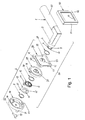
- FIGS. 1 and 6 an inventive door or window fitting is evident, which can be mounted on one side of a door leaf 17 or window frame.
- a corresponding door or window fitting is arranged, with which the in FIG. 1 screwed fitting shown bolted can be.
- the in the FIGS. 1 and 2 illustrated door or window fitting comprises a handle 1 in the form of a pusher and a rosette 2, which can be screwed to the door leaf or window frame or on an opposite, not shown rosette.
- the handle 1 is rotatably mounted in the rosette 2 and fixed axially thereto.
- the substantially L-shaped handle 1 has a neck portion 3, at the free end of a guide lug or bearing portion 4 is provided.
- the bearing section 4 serves for the rotatable mounting of the handle 1 in the rosette 2 and is accordingly cylindrical.
- the diameter of the bearing portion 4 is smaller than that of the adjacent part of the neck portion 3, so that in the transition region, a diameter stage 5 is present.
- the bearing portion 4 has a circumferential groove 6 into which a securing ring 7 can be inserted.
- a securing ring 7 In the interior of the neck portion 3 in the usual way an axially extending square hole 8 for rotatably receiving a square pin 9 (FIG. Figures 2 and 6 ) is provided, which cooperates with a lock.
- the bearing portion 4 further comprises two diametrically opposed axial slots 10, which, starting from the free end of the bearing portion 4, at least over the majority of the Length of the bearing section 4 extend. These axial slots are, as will be explained in more detail later, on the one hand for fixing an inner end portion 11 of a retaining spring 12 and on the other hand for rotationally fixed fixing a Drehanschlagelements 13 on the bearing section. 4
- the rosette 2 also has a plate-shaped mounting base 14, which in the present embodiment has the shape of a circular plate.
- a central, circular opening 15 serves to pass through the square pin 9 and also makes it possible that the free end portion of the bearing portion 4 in the mounted state of the fitting can still slightly protrude into the opening 15.
- the mounting base 14 is by means of two screws 16 on the door leaf 17 ( Figures 2 and 6 ) or window frame screwed.
- the mounting base 14 has two opposite screw holes 18, 19, wherein the screw hole 18 is provided with a through hole, so that a fixing screw 16 can be inserted therethrough, while the screw hole 19 has an internal thread, so that one of the opposite Side introduced fixing screw 16 can be screwed in the screw hole 19.
- the screw holes 18, 19 penetrate cylindrical pins 20, 21, which protrude in the axial direction from the rear of the mounting base 14 to the rear, that is in the direction of the door leaf 17 or window frame, and can be inserted into correspondingly sized through holes of the door leaf 17 and the window frame.
- the cylindrical pins 20, 21 thus simultaneously act as anti-rotation elements with which the mounting base 14 can be fixed against rotation on the door leaf 17 or window frame.
- the mounting base 14 has an end wall 22 which can be brought to the door leaf 17 or window frame to the plant, and a peripheral wall 23 which projects axially beyond the end wall 22. From the peripheral wall 23, two diametrically opposed radial projections 24 extend radially inwardly, which are part of a bayonet-type locking mechanism, which cooperates with a bearing plate 29.
- the radial projections 24 have a predetermined axial distance from the end wall 22.
- In the end wall 22 are further provided axially aligned with the radial projections 24 recesses 25 whose length is slightly larger than that of the radial projections 24th
- anti-rotation element 58 In a recess of the end wall 22 of the mounting base 14 designed as an insert anti-rotation element 58 is inserted.
- This anti-rotation element 58 has a securing tongue 59, which extends radially beyond the peripheral wall 23 from a section 60 arranged in the circumferential direction of the mounting base 14.
- the anti-rotation element 58 is thus formed substantially T-shaped, wherein the portion 60 circular arc runs.
- the anti-rotation element 58 can be made, for example, by being punched out of a flat plate.
- the recess in the end wall 22 of the mounting base 14, in which the anti-rotation element 58 is inserted has a depth that is suitably deep or only slightly deeper than the thickness of the anti-rotation element 58.
- the anti-rotation element 58 is automatically fixed captive on the mounting base 14 between the mounting base 14 and the door leaf 17 and window frame. Separate fastening means for the anti-rotation element 58 are therefore not required.
- the anti-rotation element 58 is, as will be explained in more detail later, for rotational locking of a blind ring 50, which is plugged onto a cap 28 at the end of fitting mounting.
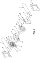
- the mounting base 14 can, as out FIG. 6 can be screwed separately on the door leaf 17 or window frame and serves to hold a separately preassembled module 26, which, as from FIG. 1 3, in addition to the handle 1, the following elements are included: a sliding ring 27, the cover cap 28, the bearing disc 29 for rotatably supporting the handle 1, a sliding ring 30, the retaining spring 12, the rotation stop element 13 and the retaining ring 7. All the above elements can, before the assembly 26 is mounted on the mounting base 14, mounted in advance on the bearing portion 4 of the handle 1 and fixed there axially immovable, wherein they are to an axial direction are determined by the diameter step 5 and the other axial direction through the locking ring 7.
- the bearing disk 29 has an end wall 31 and a peripheral wall 32 protruding therefrom in the axial direction.
- a central passage opening 33 which is provided in the end wall 31, serves for passing and for rotatably supporting the bearing portion 4 of the handle 1.
- a pin-shaped rotation stop 34 extends axially to the rear, with a further rotation stop 35 of Drehanschlagelements 13 cooperates.
- two diametrically opposed locking tongues 36 are provided, which extend in the circumferential direction and adjacent to adjacent axial recesses 37, which are introduced from the outside into the peripheral wall 32.
- the locking tongues 36 and axial recesses 37 belong to the already mentioned bayonet-type locking mechanism, with which the bearing plate 29 can be fastened to the mounting base 14.
- the bearing plate 29 further in its immediately adjacent to the passage opening 33 edge region three axial projections 38 which are arranged distributed regularly over the circumference of the passage opening 33 and accordingly spaced from each other.
- the height of the axial projections 38 corresponds at least substantially to the thickness of the material of which the cover cap 28 consists.
- the axial projections 38 serve for rotational locking of the cap 28 when the bearing plate 29 and the cap 28 are arranged directly next to each other.
- the outer diameter of the bearing plate 29 is only slightly smaller than the inner diameter of the mounting base 14 in the region of the peripheral wall 23, so that the bearing plate 29 can be inserted with little radial play in the mounting base 14 and then rotated so that the locking tongues 36 of the bearing plate 29th engage behind the radial projections 24 of the bearing base 14, whereby the bearing plate 29 is locked to the mounting base 14 like a bayonet.
- the cap 28 has an end wall 39 with a central passage opening 40.
- the central passage opening 40 in turn serves to pass the bearing portion 4 of the handle 1.
- 40 radially projecting recesses 42 are provided in the edge region of the through hole, which are adapted to the shape of the projections 38 of the bearing plate 29, so that the projections 38 positively in the recesses 42 engage and can cause the aforementioned rotation lock when the bearing plate 29 and cap 28 are directly adjacent to each other.
- the number and shape of the projections 38 and recesses 42 may vary widely.
- the cap 28 has such a depth T, that in the finished assembled state of the door or window fitting a distance A to the door leaf 17 or window frame Has.
- the inner edge 48 of the shoulder portions 41 which project furthest in the direction of the door leaf 17 or window frame, have a distance A to the door leaf 17 or window frame.
- This distance A causes that during a rotary movement of the cap 28 for bayonet-like locking of the bearing plate 29 on the mounting base 14, the cap 28 does not come into contact with the door leaf 17 or window frame, thereby scratching is avoided.
- the shoulder sections 41 are isolated, circumferentially distributed shoulder sections. This means that the individual shoulder portions 41 are separated by gaps 49 in the circumferential direction. Alternatively, however, the intermediate spaces 49 can also be omitted, so that a peripheral peripheral wall is formed, which extends in the same manner as the shoulder portions 41 from the end wall 39 in the direction of the door leaf 17 or window frame.
- the shoulder portions 41 are used for attaching and clamping the blind ring 50, which is adapted to the outer contour of the cap 28 and is accordingly designed as a square Aufsteckrahmen.
- the blend ring 50 has an L-shaped cross-sectional profile.
- the depth of the bezel 50 ie the depth of its peripheral wall 51, is greater than the depth T of the cap 28 and dimensioned such that the peripheral wall 51 of the bezel 50 in the direction of the door leaf 17 or window frame not only the cap 28, but also the Covered by the gap A gap when the aperture ring 50 on the shoulder portions 41 of the cap 28 is attached.
- the frame-shaped circumferential wall 52 of the aperture ring 50 is located on the slightly recessed edge region 53 (FIG. FIG. 1 ) of the end wall 39 of the cap 28 at.
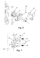
- FIG. 5 is further seen that in the peripheral wall 51 of the diaphragm 50, a recess 54 is provided.
- the securing tines 59 of the fixed to the mounting base 14 anti-rotation element 58 engages with little lateral play or play, when the aperture ring 50 is attached to the cap 28. Due to the interaction of recess 54 and locking tongue 59, therefore, a twist lock is provided which prevents rotation of the bezel 50 together with the cap 28 relative to the mounting base 14 with fitting mounted, as long as the bezel 50 is in the mounted end position. As a result, scratching the door leaf or window frame surface is prevented.
- the recess 54 serves for insertion of a tool, such as screwdriver, when the blind ring 50 is to be removed from the cap 28 again.
- the hold-up spring 12 consists of a leaf spring with a plurality of superposed windings, which enclose a central passage opening 43.
- the passage opening 43 is dimensioned so that the bearing portion 4 of the handle 1 can be inserted therethrough.
- the inner end portion 11 of the hold-up spring 12 is bent radially inwardly and is radially after inside, that it can be inserted in one of the axial slots 10 of the bearing portion 4.
- the retaining spring 12 is fixed with its inner end portion 11 on the bearing section 4.
- the outer end portion 44 of the retaining spring 11, however, is bent outwardly, whereby a hook is formed, with which the retaining spring 12 can be suspended on the rotation stop 34 with bias.
- the biasing force of the hold-up spring 12 therefore acts in the in FIG. 1 shown embodiment such that the handle 1 is urged counterclockwise in the illustrated horizontal starting position.
- the illustrated Dregehgangsposition the handle 1 is determined by the rotation stopper 13, which is formed in the illustrated embodiment as an annular disc.
- the rotation stop element 13 has a central passage opening 45. This is dimensioned so that the rotational stop element 13 can be plugged onto the bearing portion 4 of the handle 1.
- Two inwardly projecting radial projections 46 engage in the axial slots 10 of the bearing portion 4, whereby the rotational stop member 13 is rotatably connected to the handle 1.
- the rotational stop 35 of the Drehanschlagelements 13 consists of a radially outwardly projecting nose which abuts under the action of the retaining spring 12 in the rotational output position of the handle 1 on the pin-like rotation stop 34 of the bearing plate 29.
- the mounting base 14 is initially screwed by means of the screws 16 on the door leaf 17 or window frame. Subsequently, the preassembled module 26 is approximated to the mounting base 14 in the axial direction.
- the handle 1 is located in the rotational output position, that is, the grip part 47 is arranged horizontally. In this position, the square hole 8 is aligned in the neck portion 3 such that the square pin 9 can be inserted into the square hole 8.
- the bearing plate 29 is in the immediate vicinity of the mounting base 14, the cap 28 is engaged with the fingers and rotated by a certain angular amount, which may be 25 degrees, for example, against the biasing force of the retaining spring 12 in the counterclockwise direction (arrow 57). Since the bearing plate 29 is rotatably connected to the cap 28, the bearing plate 29 is rotated accordingly. This rotation causes the provided on the outer circumference of the bearing plate 29 axial recesses 37 are aligned with the radial projections 24 of the mounting base 14, whereby the bearing plate 29 can be pushed completely in the axial direction on the mounting base 14. In the fully pushed state, the bearing plate 29 is located substantially within the mounting base 14, while the cap 28 partially covers the mounting base 14. The peripheral wall 23 of the mounting base 14 thus extends into a space between the bearing plate 29 and the shoulder portions 41 of the cap 28th
Landscapes
- Engineering & Computer Science (AREA)
- Mechanical Engineering (AREA)
- Hinges (AREA)
Priority Applications (1)
| Application Number | Priority Date | Filing Date | Title |
|---|---|---|---|
| EP13004156.9A EP2840203B1 (fr) | 2013-08-22 | 2013-08-22 | Ferrure de porte ou de fenêtre dotée d'une plaque de couverture en plusieurs parties |
Applications Claiming Priority (1)
| Application Number | Priority Date | Filing Date | Title |
|---|---|---|---|
| EP13004156.9A EP2840203B1 (fr) | 2013-08-22 | 2013-08-22 | Ferrure de porte ou de fenêtre dotée d'une plaque de couverture en plusieurs parties |
Publications (2)
| Publication Number | Publication Date |
|---|---|
| EP2840203A1 true EP2840203A1 (fr) | 2015-02-25 |
| EP2840203B1 EP2840203B1 (fr) | 2016-02-24 |
Family
ID=49033786
Family Applications (1)
| Application Number | Title | Priority Date | Filing Date |
|---|---|---|---|
| EP13004156.9A Active EP2840203B1 (fr) | 2013-08-22 | 2013-08-22 | Ferrure de porte ou de fenêtre dotée d'une plaque de couverture en plusieurs parties |
Country Status (1)
| Country | Link |
|---|---|
| EP (1) | EP2840203B1 (fr) |
Cited By (7)
| Publication number | Priority date | Publication date | Assignee | Title |
|---|---|---|---|---|
| US20180298635A1 (en) * | 2017-04-18 | 2018-10-18 | Taiwan Fu Hsing Industrial Co., Ltd. | Rebound apparatus for a lock assembly |
| US20190211580A1 (en) * | 2016-04-18 | 2019-07-11 | Kuriki Manufacture Co., Ltd | Locking structure for cover covering handle seat |
| DE102019200115A1 (de) * | 2019-01-08 | 2020-07-09 | Karcher Gmbh | Türschließsystem |
| EP4151819A1 (fr) * | 2021-09-16 | 2023-03-22 | Dormakaba USA Inc. | Système de fixation pour un système de verrouillage |
| EP4159957A1 (fr) * | 2021-09-15 | 2023-04-05 | Karcher GmbH | Système de fermeture de porte |
| US20230295953A1 (en) * | 2020-08-04 | 2023-09-21 | Gulesci Saffet | Smart assembly handle mechanism |
| GB2628638A (en) * | 2023-03-31 | 2024-10-02 | Joseph Giles Ltd | Rose and handle |
Families Citing this family (1)
| Publication number | Priority date | Publication date | Assignee | Title |
|---|---|---|---|---|
| EP4124707A1 (fr) * | 2021-07-28 | 2023-02-01 | Dormakaba Danmark | Ensemble de fixation de porte et système de verrouillage de porte rabattable |
Citations (7)
| Publication number | Priority date | Publication date | Assignee | Title |
|---|---|---|---|---|
| GB1069218A (en) * | 1965-04-06 | 1967-05-17 | Lilly & Sons Ltd B | Lever-handle door latch fittings |
| WO1992012314A1 (fr) * | 1991-01-11 | 1992-07-23 | Whitco Pty. Ltd. | Ensemble poignee |
| US5732578A (en) * | 1995-02-24 | 1998-03-31 | Hyundai Metal Co., Ltd. | Device for maintaining the horizontality of a door lock lever |
| EP1882798A1 (fr) * | 2006-07-27 | 2008-01-30 | ALMAR s.p.a. | Ferrure pour porte ou fenêtre |
| EP2182144A1 (fr) * | 2008-10-31 | 2010-05-05 | ALMAR s.p.a. | Rebord de porte ou de fenêtre |
| DE202011000933U1 (de) * | 2011-04-19 | 2011-08-10 | Franz Schneider Brakel Gmbh & Co. Kg | Drückerlagerung eines Tür- oder Fensterdrückers |
| WO2013050915A1 (fr) * | 2011-10-04 | 2013-04-11 | MANITAL S.r.l. | Rosette d'attachement et procédé d'adaptation d'une poignée à un accessoire de porte ou de fenêtre |
-
2013
- 2013-08-22 EP EP13004156.9A patent/EP2840203B1/fr active Active
Patent Citations (7)
| Publication number | Priority date | Publication date | Assignee | Title |
|---|---|---|---|---|
| GB1069218A (en) * | 1965-04-06 | 1967-05-17 | Lilly & Sons Ltd B | Lever-handle door latch fittings |
| WO1992012314A1 (fr) * | 1991-01-11 | 1992-07-23 | Whitco Pty. Ltd. | Ensemble poignee |
| US5732578A (en) * | 1995-02-24 | 1998-03-31 | Hyundai Metal Co., Ltd. | Device for maintaining the horizontality of a door lock lever |
| EP1882798A1 (fr) * | 2006-07-27 | 2008-01-30 | ALMAR s.p.a. | Ferrure pour porte ou fenêtre |
| EP2182144A1 (fr) * | 2008-10-31 | 2010-05-05 | ALMAR s.p.a. | Rebord de porte ou de fenêtre |
| DE202011000933U1 (de) * | 2011-04-19 | 2011-08-10 | Franz Schneider Brakel Gmbh & Co. Kg | Drückerlagerung eines Tür- oder Fensterdrückers |
| WO2013050915A1 (fr) * | 2011-10-04 | 2013-04-11 | MANITAL S.r.l. | Rosette d'attachement et procédé d'adaptation d'une poignée à un accessoire de porte ou de fenêtre |
Cited By (10)
| Publication number | Priority date | Publication date | Assignee | Title |
|---|---|---|---|---|
| US20190211580A1 (en) * | 2016-04-18 | 2019-07-11 | Kuriki Manufacture Co., Ltd | Locking structure for cover covering handle seat |
| US20180298635A1 (en) * | 2017-04-18 | 2018-10-18 | Taiwan Fu Hsing Industrial Co., Ltd. | Rebound apparatus for a lock assembly |
| DE102019200115A1 (de) * | 2019-01-08 | 2020-07-09 | Karcher Gmbh | Türschließsystem |
| DE102019200115B4 (de) | 2019-01-08 | 2022-12-01 | Karcher Gmbh | Türschließsystem |
| US20230295953A1 (en) * | 2020-08-04 | 2023-09-21 | Gulesci Saffet | Smart assembly handle mechanism |
| EP4193029A4 (fr) * | 2020-08-04 | 2024-08-14 | Guelesci Saffet | Mécanisme de poignée de système intelligent |
| EP4159957A1 (fr) * | 2021-09-15 | 2023-04-05 | Karcher GmbH | Système de fermeture de porte |
| EP4151819A1 (fr) * | 2021-09-16 | 2023-03-22 | Dormakaba USA Inc. | Système de fixation pour un système de verrouillage |
| US11892120B2 (en) | 2021-09-16 | 2024-02-06 | Dormakaba Usa Inc. | Lock with serviceable keypad |
| GB2628638A (en) * | 2023-03-31 | 2024-10-02 | Joseph Giles Ltd | Rose and handle |
Also Published As
| Publication number | Publication date |
|---|---|
| EP2840203B1 (fr) | 2016-02-24 |
Similar Documents
| Publication | Publication Date | Title |
|---|---|---|
| EP2840203B1 (fr) | Ferrure de porte ou de fenêtre dotée d'une plaque de couverture en plusieurs parties | |
| EP2182144B1 (fr) | Rebord de porte ou de fenêtre | |
| DE29820711U1 (de) | Drehriegelverschluß mit Zugeinrichtung | |
| EP3271530B1 (fr) | Élément de maintien pour une poignée de porte ou de fenêtre et agencement d'une poignée de porte ou de fenêtre au niveau d'une ouverture de réception d'un cadre de fenêtre, d'un battant de porte ou similaire | |
| EP1882798B1 (fr) | Ferrure pour porte ou fenêtre | |
| DE202012008665U1 (de) | Anordnung zum Befestigen eines Pfostens an einer Rahmenleiste eines Fensters oder einer Türe mittels eines Pfostenverbinders | |
| EP3411547B1 (fr) | Serrure avec position ajustable d'un element d'arrêt sur l'arbre de fermeture | |
| EP2623828A1 (fr) | Robinet | |
| DE102015120525B4 (de) | Befestigungssystem für einen Toilettensitz, Käfig, Käfigmutter, Verwendung, Anordnung und Verfahren | |
| EP3472415B1 (fr) | Système de charnière | |
| CH710047A2 (de) | Verschluss mit den Öffnungszustand anzeigenden Signalring. | |
| EP2565351B1 (fr) | Agencement de poignée | |
| DE29722488U1 (de) | Vorreiberverschluß für dickwandige Türen, Klappen o.dgl. | |
| EP3363969B1 (fr) | Poignée d'actionnement | |
| DE102019114332A1 (de) | Schlossvorrichtung | |
| DE69208814T2 (de) | Haltevorrichtung für den Schlüssel eines Schlosses | |
| DE102013101491B4 (de) | Höheneinstellbare Rundstangenführung | |
| DE102013205061A1 (de) | Bedienungsmittel für eine Platte, Kombination zweier Bedienungsmittel und Verfahren zum klemmfesten Positionieren des Bedienungsmittels an einer Platte | |
| DE102014105342A1 (de) | WC-Sitzgelenk | |
| DE102009018781A1 (de) | Verbindungsbaugruppe | |
| DE102013211864A1 (de) | Anordnung zur Befestigung eines Pfostens an einer Kunststoff-Rahmenleiste eines Fensters oder einer Türe mittels eines Pfostenverbinders aus Kunststoff | |
| DE202018100634U1 (de) | Drehverschluss | |
| EP3045617B1 (fr) | Rosette et système de loquet de porte ou de fenêtre et d'une rosette sur une ouverture de vantail de fenêtre ou de porte ou similaire | |
| DE202007009771U1 (de) | Verbindungsbeschlag für Platten, insbesondere für Tablare | |
| EP2177696B1 (fr) | Rebord de porte ou de fenêtre |
Legal Events
| Date | Code | Title | Description |
|---|---|---|---|
| PUAI | Public reference made under article 153(3) epc to a published international application that has entered the european phase |
Free format text: ORIGINAL CODE: 0009012 |
|
| 17P | Request for examination filed |
Effective date: 20130822 |
|
| AK | Designated contracting states |
Kind code of ref document: A1 Designated state(s): AL AT BE BG CH CY CZ DE DK EE ES FI FR GB GR HR HU IE IS IT LI LT LU LV MC MK MT NL NO PL PT RO RS SE SI SK SM TR |
|
| AX | Request for extension of the european patent |
Extension state: BA ME |
|
| R17P | Request for examination filed (corrected) |
Effective date: 20150326 |
|
| RBV | Designated contracting states (corrected) |
Designated state(s): AL AT BE BG CH CY CZ DE DK EE ES FI FR GB GR HR HU IE IS IT LI LT LU LV MC MK MT NL NO PL PT RO RS SE SI SK SM TR |
|
| RIC1 | Information provided on ipc code assigned before grant |
Ipc: E05B 15/04 20060101ALN20150630BHEP Ipc: E05B 15/02 20060101ALN20150630BHEP Ipc: E05B 3/06 20060101AFI20150630BHEP |
|
| GRAP | Despatch of communication of intention to grant a patent |
Free format text: ORIGINAL CODE: EPIDOSNIGR1 |
|
| INTG | Intention to grant announced |
Effective date: 20150909 |
|
| GRAS | Grant fee paid |
Free format text: ORIGINAL CODE: EPIDOSNIGR3 |
|
| GRAA | (expected) grant |
Free format text: ORIGINAL CODE: 0009210 |
|
| AK | Designated contracting states |
Kind code of ref document: B1 Designated state(s): AL AT BE BG CH CY CZ DE DK EE ES FI FR GB GR HR HU IE IS IT LI LT LU LV MC MK MT NL NO PL PT RO RS SE SI SK SM TR |
|
| REG | Reference to a national code |
Ref country code: GB Ref legal event code: FG4D Free format text: NOT ENGLISH |
|
| REG | Reference to a national code |
Ref country code: CH Ref legal event code: EP |
|
| REG | Reference to a national code |
Ref country code: AT Ref legal event code: REF Ref document number: 776835 Country of ref document: AT Kind code of ref document: T Effective date: 20160315 |
|
| REG | Reference to a national code |
Ref country code: IE Ref legal event code: FG4D Free format text: LANGUAGE OF EP DOCUMENT: GERMAN |
|
| REG | Reference to a national code |
Ref country code: DE Ref legal event code: R096 Ref document number: 502013001975 Country of ref document: DE |
|
| REG | Reference to a national code |
Ref country code: LT Ref legal event code: MG4D |
|
| REG | Reference to a national code |
Ref country code: NL Ref legal event code: MP Effective date: 20160224 |
|
| PG25 | Lapsed in a contracting state [announced via postgrant information from national office to epo] |
Ref country code: NO Free format text: LAPSE BECAUSE OF FAILURE TO SUBMIT A TRANSLATION OF THE DESCRIPTION OR TO PAY THE FEE WITHIN THE PRESCRIBED TIME-LIMIT Effective date: 20160524 Ref country code: HR Free format text: LAPSE BECAUSE OF FAILURE TO SUBMIT A TRANSLATION OF THE DESCRIPTION OR TO PAY THE FEE WITHIN THE PRESCRIBED TIME-LIMIT Effective date: 20160224 Ref country code: FI Free format text: LAPSE BECAUSE OF FAILURE TO SUBMIT A TRANSLATION OF THE DESCRIPTION OR TO PAY THE FEE WITHIN THE PRESCRIBED TIME-LIMIT Effective date: 20160224 Ref country code: GR Free format text: LAPSE BECAUSE OF FAILURE TO SUBMIT A TRANSLATION OF THE DESCRIPTION OR TO PAY THE FEE WITHIN THE PRESCRIBED TIME-LIMIT Effective date: 20160525 Ref country code: IT Free format text: LAPSE BECAUSE OF FAILURE TO SUBMIT A TRANSLATION OF THE DESCRIPTION OR TO PAY THE FEE WITHIN THE PRESCRIBED TIME-LIMIT Effective date: 20160224 Ref country code: ES Free format text: LAPSE BECAUSE OF FAILURE TO SUBMIT A TRANSLATION OF THE DESCRIPTION OR TO PAY THE FEE WITHIN THE PRESCRIBED TIME-LIMIT Effective date: 20160224 |
|
| REG | Reference to a national code |
Ref country code: FR Ref legal event code: PLFP Year of fee payment: 4 |
|
| PG25 | Lapsed in a contracting state [announced via postgrant information from national office to epo] |
Ref country code: SE Free format text: LAPSE BECAUSE OF FAILURE TO SUBMIT A TRANSLATION OF THE DESCRIPTION OR TO PAY THE FEE WITHIN THE PRESCRIBED TIME-LIMIT Effective date: 20160224 Ref country code: LV Free format text: LAPSE BECAUSE OF FAILURE TO SUBMIT A TRANSLATION OF THE DESCRIPTION OR TO PAY THE FEE WITHIN THE PRESCRIBED TIME-LIMIT Effective date: 20160224 Ref country code: PT Free format text: LAPSE BECAUSE OF FAILURE TO SUBMIT A TRANSLATION OF THE DESCRIPTION OR TO PAY THE FEE WITHIN THE PRESCRIBED TIME-LIMIT Effective date: 20160624 Ref country code: RS Free format text: LAPSE BECAUSE OF FAILURE TO SUBMIT A TRANSLATION OF THE DESCRIPTION OR TO PAY THE FEE WITHIN THE PRESCRIBED TIME-LIMIT Effective date: 20160224 Ref country code: NL Free format text: LAPSE BECAUSE OF FAILURE TO SUBMIT A TRANSLATION OF THE DESCRIPTION OR TO PAY THE FEE WITHIN THE PRESCRIBED TIME-LIMIT Effective date: 20160224 Ref country code: LT Free format text: LAPSE BECAUSE OF FAILURE TO SUBMIT A TRANSLATION OF THE DESCRIPTION OR TO PAY THE FEE WITHIN THE PRESCRIBED TIME-LIMIT Effective date: 20160224 Ref country code: PL Free format text: LAPSE BECAUSE OF FAILURE TO SUBMIT A TRANSLATION OF THE DESCRIPTION OR TO PAY THE FEE WITHIN THE PRESCRIBED TIME-LIMIT Effective date: 20160224 |
|
| PG25 | Lapsed in a contracting state [announced via postgrant information from national office to epo] |
Ref country code: DK Free format text: LAPSE BECAUSE OF FAILURE TO SUBMIT A TRANSLATION OF THE DESCRIPTION OR TO PAY THE FEE WITHIN THE PRESCRIBED TIME-LIMIT Effective date: 20160224 Ref country code: EE Free format text: LAPSE BECAUSE OF FAILURE TO SUBMIT A TRANSLATION OF THE DESCRIPTION OR TO PAY THE FEE WITHIN THE PRESCRIBED TIME-LIMIT Effective date: 20160224 |
|
| REG | Reference to a national code |
Ref country code: DE Ref legal event code: R097 Ref document number: 502013001975 Country of ref document: DE |
|
| PG25 | Lapsed in a contracting state [announced via postgrant information from national office to epo] |
Ref country code: CZ Free format text: LAPSE BECAUSE OF FAILURE TO SUBMIT A TRANSLATION OF THE DESCRIPTION OR TO PAY THE FEE WITHIN THE PRESCRIBED TIME-LIMIT Effective date: 20160224 Ref country code: RO Free format text: LAPSE BECAUSE OF FAILURE TO SUBMIT A TRANSLATION OF THE DESCRIPTION OR TO PAY THE FEE WITHIN THE PRESCRIBED TIME-LIMIT Effective date: 20160224 Ref country code: SK Free format text: LAPSE BECAUSE OF FAILURE TO SUBMIT A TRANSLATION OF THE DESCRIPTION OR TO PAY THE FEE WITHIN THE PRESCRIBED TIME-LIMIT Effective date: 20160224 Ref country code: SM Free format text: LAPSE BECAUSE OF FAILURE TO SUBMIT A TRANSLATION OF THE DESCRIPTION OR TO PAY THE FEE WITHIN THE PRESCRIBED TIME-LIMIT Effective date: 20160224 |
|
| PG25 | Lapsed in a contracting state [announced via postgrant information from national office to epo] |
Ref country code: BE Free format text: LAPSE BECAUSE OF NON-PAYMENT OF DUE FEES Effective date: 20160831 |
|
| PLBE | No opposition filed within time limit |
Free format text: ORIGINAL CODE: 0009261 |
|
| STAA | Information on the status of an ep patent application or granted ep patent |
Free format text: STATUS: NO OPPOSITION FILED WITHIN TIME LIMIT |
|
| 26N | No opposition filed |
Effective date: 20161125 |
|
| PG25 | Lapsed in a contracting state [announced via postgrant information from national office to epo] |
Ref country code: SI Free format text: LAPSE BECAUSE OF FAILURE TO SUBMIT A TRANSLATION OF THE DESCRIPTION OR TO PAY THE FEE WITHIN THE PRESCRIBED TIME-LIMIT Effective date: 20160224 Ref country code: BG Free format text: LAPSE BECAUSE OF FAILURE TO SUBMIT A TRANSLATION OF THE DESCRIPTION OR TO PAY THE FEE WITHIN THE PRESCRIBED TIME-LIMIT Effective date: 20160524 |
|
| PG25 | Lapsed in a contracting state [announced via postgrant information from national office to epo] |
Ref country code: MC Free format text: LAPSE BECAUSE OF FAILURE TO SUBMIT A TRANSLATION OF THE DESCRIPTION OR TO PAY THE FEE WITHIN THE PRESCRIBED TIME-LIMIT Effective date: 20160224 |
|
| REG | Reference to a national code |
Ref country code: CH Ref legal event code: PL |
|
| PG25 | Lapsed in a contracting state [announced via postgrant information from national office to epo] |
Ref country code: CH Free format text: LAPSE BECAUSE OF NON-PAYMENT OF DUE FEES Effective date: 20160831 Ref country code: LI Free format text: LAPSE BECAUSE OF NON-PAYMENT OF DUE FEES Effective date: 20160831 |
|
| REG | Reference to a national code |
Ref country code: IE Ref legal event code: MM4A |
|
| PG25 | Lapsed in a contracting state [announced via postgrant information from national office to epo] |
Ref country code: IE Free format text: LAPSE BECAUSE OF NON-PAYMENT OF DUE FEES Effective date: 20160822 |
|
| REG | Reference to a national code |
Ref country code: FR Ref legal event code: PLFP Year of fee payment: 5 |
|
| PG25 | Lapsed in a contracting state [announced via postgrant information from national office to epo] |
Ref country code: LU Free format text: LAPSE BECAUSE OF NON-PAYMENT OF DUE FEES Effective date: 20160822 |
|
| GBPC | Gb: european patent ceased through non-payment of renewal fee |
Effective date: 20170822 |
|
| PG25 | Lapsed in a contracting state [announced via postgrant information from national office to epo] |
Ref country code: HU Free format text: LAPSE BECAUSE OF FAILURE TO SUBMIT A TRANSLATION OF THE DESCRIPTION OR TO PAY THE FEE WITHIN THE PRESCRIBED TIME-LIMIT; INVALID AB INITIO Effective date: 20130822 |
|
| PG25 | Lapsed in a contracting state [announced via postgrant information from national office to epo] |
Ref country code: IS Free format text: LAPSE BECAUSE OF FAILURE TO SUBMIT A TRANSLATION OF THE DESCRIPTION OR TO PAY THE FEE WITHIN THE PRESCRIBED TIME-LIMIT Effective date: 20160224 Ref country code: MK Free format text: LAPSE BECAUSE OF FAILURE TO SUBMIT A TRANSLATION OF THE DESCRIPTION OR TO PAY THE FEE WITHIN THE PRESCRIBED TIME-LIMIT Effective date: 20160224 Ref country code: MT Free format text: LAPSE BECAUSE OF FAILURE TO SUBMIT A TRANSLATION OF THE DESCRIPTION OR TO PAY THE FEE WITHIN THE PRESCRIBED TIME-LIMIT Effective date: 20160224 Ref country code: CY Free format text: LAPSE BECAUSE OF FAILURE TO SUBMIT A TRANSLATION OF THE DESCRIPTION OR TO PAY THE FEE WITHIN THE PRESCRIBED TIME-LIMIT Effective date: 20160224 |
|
| REG | Reference to a national code |
Ref country code: DE Ref legal event code: R082 Ref document number: 502013001975 Country of ref document: DE Representative=s name: FLACH BAUER & PARTNER PATENTANWAELTE MBB, DE Ref country code: DE Ref legal event code: R082 Ref document number: 502013001975 Country of ref document: DE Representative=s name: FLACH BAUER STAHL PATENTANWAELTE PARTNERSCHAFT, DE |
|
| PG25 | Lapsed in a contracting state [announced via postgrant information from national office to epo] |
Ref country code: GB Free format text: LAPSE BECAUSE OF NON-PAYMENT OF DUE FEES Effective date: 20170822 |
|
| REG | Reference to a national code |
Ref country code: FR Ref legal event code: PLFP Year of fee payment: 6 |
|
| PG25 | Lapsed in a contracting state [announced via postgrant information from national office to epo] |
Ref country code: AL Free format text: LAPSE BECAUSE OF FAILURE TO SUBMIT A TRANSLATION OF THE DESCRIPTION OR TO PAY THE FEE WITHIN THE PRESCRIBED TIME-LIMIT Effective date: 20160224 Ref country code: TR Free format text: LAPSE BECAUSE OF FAILURE TO SUBMIT A TRANSLATION OF THE DESCRIPTION OR TO PAY THE FEE WITHIN THE PRESCRIBED TIME-LIMIT Effective date: 20160224 |
|
| P01 | Opt-out of the competence of the unified patent court (upc) registered |
Effective date: 20230524 |
|
| PGFP | Annual fee paid to national office [announced via postgrant information from national office to epo] |
Ref country code: AT Payment date: 20230818 Year of fee payment: 11 |
|
| PGFP | Annual fee paid to national office [announced via postgrant information from national office to epo] |
Ref country code: DE Payment date: 20240819 Year of fee payment: 12 |
|
| PGFP | Annual fee paid to national office [announced via postgrant information from national office to epo] |
Ref country code: FR Payment date: 20240823 Year of fee payment: 12 |