EP3858792B1 - Verfahren und vorrichtung zum direkten trocknen von anorganischem schlamm mit einem trommelziehverfahren - Google Patents
Verfahren und vorrichtung zum direkten trocknen von anorganischem schlamm mit einem trommelziehverfahren Download PDFInfo
- Publication number
- EP3858792B1 EP3858792B1 EP19866463.3A EP19866463A EP3858792B1 EP 3858792 B1 EP3858792 B1 EP 3858792B1 EP 19866463 A EP19866463 A EP 19866463A EP 3858792 B1 EP3858792 B1 EP 3858792B1
- Authority
- EP
- European Patent Office
- Prior art keywords
- sludge
- slag
- drum
- drying
- inorganic
- Prior art date
- Legal status (The legal status is an assumption and is not a legal conclusion. Google has not performed a legal analysis and makes no representation as to the accuracy of the status listed.)
- Active
Links
Images
Classifications
-
- C—CHEMISTRY; METALLURGY
- C02—TREATMENT OF WATER, WASTE WATER, SEWAGE, OR SLUDGE
- C02F—TREATMENT OF WATER, WASTE WATER, SEWAGE, OR SLUDGE
- C02F11/00—Treatment of sludge; Devices therefor
- C02F11/12—Treatment of sludge; Devices therefor by de-watering, drying or thickening
- C02F11/121—Treatment of sludge; Devices therefor by de-watering, drying or thickening by mechanical de-watering
- C02F11/126—Treatment of sludge; Devices therefor by de-watering, drying or thickening by mechanical de-watering using drum filters
-
- C—CHEMISTRY; METALLURGY
- C02—TREATMENT OF WATER, WASTE WATER, SEWAGE, OR SLUDGE
- C02F—TREATMENT OF WATER, WASTE WATER, SEWAGE, OR SLUDGE
- C02F11/00—Treatment of sludge; Devices therefor
- C02F11/12—Treatment of sludge; Devices therefor by de-watering, drying or thickening
- C02F11/13—Treatment of sludge; Devices therefor by de-watering, drying or thickening by heating
-
- C—CHEMISTRY; METALLURGY
- C02—TREATMENT OF WATER, WASTE WATER, SEWAGE, OR SLUDGE
- C02F—TREATMENT OF WATER, WASTE WATER, SEWAGE, OR SLUDGE
- C02F11/00—Treatment of sludge; Devices therefor
- C02F11/12—Treatment of sludge; Devices therefor by de-watering, drying or thickening
-
- B—PERFORMING OPERATIONS; TRANSPORTING
- B01—PHYSICAL OR CHEMICAL PROCESSES OR APPARATUS IN GENERAL
- B01D—SEPARATION
- B01D53/00—Separation of gases or vapours; Recovering vapours of volatile solvents from gases; Chemical or biological purification of waste gases, e.g. engine exhaust gases, smoke, fumes, flue gases, aerosols
- B01D53/02—Separation of gases or vapours; Recovering vapours of volatile solvents from gases; Chemical or biological purification of waste gases, e.g. engine exhaust gases, smoke, fumes, flue gases, aerosols by adsorption, e.g. preparative gas chromatography
-
- B—PERFORMING OPERATIONS; TRANSPORTING
- B01—PHYSICAL OR CHEMICAL PROCESSES OR APPARATUS IN GENERAL
- B01D—SEPARATION
- B01D53/00—Separation of gases or vapours; Recovering vapours of volatile solvents from gases; Chemical or biological purification of waste gases, e.g. engine exhaust gases, smoke, fumes, flue gases, aerosols
- B01D53/02—Separation of gases or vapours; Recovering vapours of volatile solvents from gases; Chemical or biological purification of waste gases, e.g. engine exhaust gases, smoke, fumes, flue gases, aerosols by adsorption, e.g. preparative gas chromatography
- B01D53/04—Separation of gases or vapours; Recovering vapours of volatile solvents from gases; Chemical or biological purification of waste gases, e.g. engine exhaust gases, smoke, fumes, flue gases, aerosols by adsorption, e.g. preparative gas chromatography with stationary adsorbents
-
- B—PERFORMING OPERATIONS; TRANSPORTING
- B01—PHYSICAL OR CHEMICAL PROCESSES OR APPARATUS IN GENERAL
- B01D—SEPARATION
- B01D53/00—Separation of gases or vapours; Recovering vapours of volatile solvents from gases; Chemical or biological purification of waste gases, e.g. engine exhaust gases, smoke, fumes, flue gases, aerosols
- B01D53/14—Separation of gases or vapours; Recovering vapours of volatile solvents from gases; Chemical or biological purification of waste gases, e.g. engine exhaust gases, smoke, fumes, flue gases, aerosols by absorption
-
- B—PERFORMING OPERATIONS; TRANSPORTING
- B01—PHYSICAL OR CHEMICAL PROCESSES OR APPARATUS IN GENERAL
- B01D—SEPARATION
- B01D53/00—Separation of gases or vapours; Recovering vapours of volatile solvents from gases; Chemical or biological purification of waste gases, e.g. engine exhaust gases, smoke, fumes, flue gases, aerosols
- B01D53/34—Chemical or biological purification of waste gases
- B01D53/38—Removing components of undefined structure
- B01D53/44—Organic components
-
- B—PERFORMING OPERATIONS; TRANSPORTING
- B01—PHYSICAL OR CHEMICAL PROCESSES OR APPARATUS IN GENERAL
- B01D—SEPARATION
- B01D53/00—Separation of gases or vapours; Recovering vapours of volatile solvents from gases; Chemical or biological purification of waste gases, e.g. engine exhaust gases, smoke, fumes, flue gases, aerosols
- B01D53/34—Chemical or biological purification of waste gases
- B01D53/46—Removing components of defined structure
- B01D53/48—Sulfur compounds
-
- B—PERFORMING OPERATIONS; TRANSPORTING
- B01—PHYSICAL OR CHEMICAL PROCESSES OR APPARATUS IN GENERAL
- B01D—SEPARATION
- B01D53/00—Separation of gases or vapours; Recovering vapours of volatile solvents from gases; Chemical or biological purification of waste gases, e.g. engine exhaust gases, smoke, fumes, flue gases, aerosols
- B01D53/34—Chemical or biological purification of waste gases
- B01D53/46—Removing components of defined structure
- B01D53/72—Organic compounds not provided for in groups B01D53/48 - B01D53/70, e.g. hydrocarbons
-
- B—PERFORMING OPERATIONS; TRANSPORTING
- B01—PHYSICAL OR CHEMICAL PROCESSES OR APPARATUS IN GENERAL
- B01D—SEPARATION
- B01D53/00—Separation of gases or vapours; Recovering vapours of volatile solvents from gases; Chemical or biological purification of waste gases, e.g. engine exhaust gases, smoke, fumes, flue gases, aerosols
- B01D53/34—Chemical or biological purification of waste gases
- B01D53/74—General processes for purification of waste gases; Apparatus or devices specially adapted therefor
- B01D53/77—Liquid phase processes
- B01D53/78—Liquid phase processes with gas-liquid contact
-
- C—CHEMISTRY; METALLURGY
- C21—METALLURGY OF IRON
- C21B—MANUFACTURE OF IRON OR STEEL
- C21B3/00—General features in the manufacture of pig-iron
- C21B3/04—Recovery of by-products, e.g. slag
- C21B3/06—Treatment of liquid slag
-
- C—CHEMISTRY; METALLURGY
- C21—METALLURGY OF IRON
- C21B—MANUFACTURE OF IRON OR STEEL
- C21B3/00—General features in the manufacture of pig-iron
- C21B3/04—Recovery of by-products, e.g. slag
- C21B3/06—Treatment of liquid slag
- C21B3/08—Cooling slag
-
- F—MECHANICAL ENGINEERING; LIGHTING; HEATING; WEAPONS; BLASTING
- F26—DRYING
- F26B—DRYING SOLID MATERIALS OR OBJECTS BY REMOVING LIQUID THEREFROM
- F26B11/00—Machines or apparatus for drying solid materials or objects with movement which is non-progressive
- F26B11/02—Machines or apparatus for drying solid materials or objects with movement which is non-progressive in moving drums or other mainly-closed receptacles
-
- F—MECHANICAL ENGINEERING; LIGHTING; HEATING; WEAPONS; BLASTING
- F26—DRYING
- F26B—DRYING SOLID MATERIALS OR OBJECTS BY REMOVING LIQUID THEREFROM
- F26B11/00—Machines or apparatus for drying solid materials or objects with movement which is non-progressive
- F26B11/02—Machines or apparatus for drying solid materials or objects with movement which is non-progressive in moving drums or other mainly-closed receptacles
- F26B11/04—Machines or apparatus for drying solid materials or objects with movement which is non-progressive in moving drums or other mainly-closed receptacles rotating about a horizontal or slightly-inclined axis
-
- F—MECHANICAL ENGINEERING; LIGHTING; HEATING; WEAPONS; BLASTING
- F26—DRYING
- F26B—DRYING SOLID MATERIALS OR OBJECTS BY REMOVING LIQUID THEREFROM
- F26B11/00—Machines or apparatus for drying solid materials or objects with movement which is non-progressive
- F26B11/02—Machines or apparatus for drying solid materials or objects with movement which is non-progressive in moving drums or other mainly-closed receptacles
- F26B11/04—Machines or apparatus for drying solid materials or objects with movement which is non-progressive in moving drums or other mainly-closed receptacles rotating about a horizontal or slightly-inclined axis
- F26B11/0463—Machines or apparatus for drying solid materials or objects with movement which is non-progressive in moving drums or other mainly-closed receptacles rotating about a horizontal or slightly-inclined axis having internal elements, e.g. which are being moved or rotated by means other than the rotating drum wall
- F26B11/0468—Machines or apparatus for drying solid materials or objects with movement which is non-progressive in moving drums or other mainly-closed receptacles rotating about a horizontal or slightly-inclined axis having internal elements, e.g. which are being moved or rotated by means other than the rotating drum wall for disintegrating, crushing, or for being mixed with the materials to be dried
- F26B11/0472—Machines or apparatus for drying solid materials or objects with movement which is non-progressive in moving drums or other mainly-closed receptacles rotating about a horizontal or slightly-inclined axis having internal elements, e.g. which are being moved or rotated by means other than the rotating drum wall for disintegrating, crushing, or for being mixed with the materials to be dried the elements being loose bodies or materials, e.g. balls, which may have a sorbent effect
-
- F—MECHANICAL ENGINEERING; LIGHTING; HEATING; WEAPONS; BLASTING
- F26—DRYING
- F26B—DRYING SOLID MATERIALS OR OBJECTS BY REMOVING LIQUID THEREFROM
- F26B25/00—Details of general application not covered by group F26B21/00 or F26B23/00
- F26B25/005—Treatment of dryer exhaust gases
- F26B25/006—Separating volatiles, e.g. recovering solvents from dryer exhaust gases
-
- F—MECHANICAL ENGINEERING; LIGHTING; HEATING; WEAPONS; BLASTING
- F26—DRYING
- F26B—DRYING SOLID MATERIALS OR OBJECTS BY REMOVING LIQUID THEREFROM
- F26B3/00—Drying solid materials or objects by processes involving the application of heat
- F26B3/18—Drying solid materials or objects by processes involving the application of heat by conduction, i.e. the heat is conveyed from the heat source, e.g. gas flame, to the materials or objects to be dried by direct contact
- F26B3/20—Drying solid materials or objects by processes involving the application of heat by conduction, i.e. the heat is conveyed from the heat source, e.g. gas flame, to the materials or objects to be dried by direct contact the heat source being a heated surface, e.g. a moving belt or conveyor
- F26B3/205—Drying solid materials or objects by processes involving the application of heat by conduction, i.e. the heat is conveyed from the heat source, e.g. gas flame, to the materials or objects to be dried by direct contact the heat source being a heated surface, e.g. a moving belt or conveyor the materials to be dried covering or being mixed with heated inert particles which may be recycled
-
- B—PERFORMING OPERATIONS; TRANSPORTING
- B01—PHYSICAL OR CHEMICAL PROCESSES OR APPARATUS IN GENERAL
- B01D—SEPARATION
- B01D2251/00—Reactants
- B01D2251/30—Alkali metal compounds
-
- B—PERFORMING OPERATIONS; TRANSPORTING
- B01—PHYSICAL OR CHEMICAL PROCESSES OR APPARATUS IN GENERAL
- B01D—SEPARATION
- B01D2253/00—Adsorbents used in seperation treatment of gases and vapours
- B01D2253/10—Inorganic adsorbents
- B01D2253/102—Carbon
-
- B—PERFORMING OPERATIONS; TRANSPORTING
- B01—PHYSICAL OR CHEMICAL PROCESSES OR APPARATUS IN GENERAL
- B01D—SEPARATION
- B01D2258/00—Sources of waste gases
- B01D2258/02—Other waste gases
-
- B—PERFORMING OPERATIONS; TRANSPORTING
- B01—PHYSICAL OR CHEMICAL PROCESSES OR APPARATUS IN GENERAL
- B01D—SEPARATION
- B01D47/00—Separating dispersed particles from gases, air or vapours by liquid as separating agent
- B01D47/06—Spray cleaning
-
- C—CHEMISTRY; METALLURGY
- C02—TREATMENT OF WATER, WASTE WATER, SEWAGE, OR SLUDGE
- C02F—TREATMENT OF WATER, WASTE WATER, SEWAGE, OR SLUDGE
- C02F11/00—Treatment of sludge; Devices therefor
- C02F11/12—Treatment of sludge; Devices therefor by de-watering, drying or thickening
- C02F11/14—Treatment of sludge; Devices therefor by de-watering, drying or thickening with addition of chemical agents
- C02F11/143—Treatment of sludge; Devices therefor by de-watering, drying or thickening with addition of chemical agents using inorganic substances
-
- C—CHEMISTRY; METALLURGY
- C02—TREATMENT OF WATER, WASTE WATER, SEWAGE, OR SLUDGE
- C02F—TREATMENT OF WATER, WASTE WATER, SEWAGE, OR SLUDGE
- C02F2103/00—Nature of the water, waste water, sewage or sludge to be treated
- C02F2103/16—Nature of the water, waste water, sewage or sludge to be treated from metallurgical processes, i.e. from the production, refining or treatment of metals, e.g. galvanic wastes
-
- C—CHEMISTRY; METALLURGY
- C02—TREATMENT OF WATER, WASTE WATER, SEWAGE, OR SLUDGE
- C02F—TREATMENT OF WATER, WASTE WATER, SEWAGE, OR SLUDGE
- C02F2103/00—Nature of the water, waste water, sewage or sludge to be treated
- C02F2103/18—Nature of the water, waste water, sewage or sludge to be treated from the purification of gaseous effluents
-
- C—CHEMISTRY; METALLURGY
- C02—TREATMENT OF WATER, WASTE WATER, SEWAGE, OR SLUDGE
- C02F—TREATMENT OF WATER, WASTE WATER, SEWAGE, OR SLUDGE
- C02F2303/00—Specific treatment goals
- C02F2303/06—Sludge reduction, e.g. by lysis
-
- C—CHEMISTRY; METALLURGY
- C02—TREATMENT OF WATER, WASTE WATER, SEWAGE, OR SLUDGE
- C02F—TREATMENT OF WATER, WASTE WATER, SEWAGE, OR SLUDGE
- C02F2303/00—Specific treatment goals
- C02F2303/10—Energy recovery
-
- C—CHEMISTRY; METALLURGY
- C02—TREATMENT OF WATER, WASTE WATER, SEWAGE, OR SLUDGE
- C02F—TREATMENT OF WATER, WASTE WATER, SEWAGE, OR SLUDGE
- C02F2303/00—Specific treatment goals
- C02F2303/24—Separation of coarse particles, e.g. by using sieves or screens
-
- C—CHEMISTRY; METALLURGY
- C02—TREATMENT OF WATER, WASTE WATER, SEWAGE, OR SLUDGE
- C02F—TREATMENT OF WATER, WASTE WATER, SEWAGE, OR SLUDGE
- C02F2303/00—Specific treatment goals
- C02F2303/26—Reducing the size of particles, liquid droplets or bubbles, e.g. by crushing, grinding, spraying, creation of microbubbles or nanobubbles
-
- C—CHEMISTRY; METALLURGY
- C21—METALLURGY OF IRON
- C21B—MANUFACTURE OF IRON OR STEEL
- C21B2400/00—Treatment of slags originating from iron or steel processes
- C21B2400/02—Physical or chemical treatment of slags
-
- C—CHEMISTRY; METALLURGY
- C21—METALLURGY OF IRON
- C21B—MANUFACTURE OF IRON OR STEEL
- C21B2400/00—Treatment of slags originating from iron or steel processes
- C21B2400/02—Physical or chemical treatment of slags
- C21B2400/022—Methods of cooling or quenching molten slag
- C21B2400/028—Methods of cooling or quenching molten slag with the permanent addition of cooled slag or other solids
-
- C—CHEMISTRY; METALLURGY
- C21—METALLURGY OF IRON
- C21B—MANUFACTURE OF IRON OR STEEL
- C21B2400/00—Treatment of slags originating from iron or steel processes
- C21B2400/05—Apparatus features
- C21B2400/052—Apparatus features including rotating parts
-
- C—CHEMISTRY; METALLURGY
- C21—METALLURGY OF IRON
- C21B—MANUFACTURE OF IRON OR STEEL
- C21B2400/00—Treatment of slags originating from iron or steel processes
- C21B2400/05—Apparatus features
- C21B2400/052—Apparatus features including rotating parts
- C21B2400/056—Drums whereby slag is poured on or in between
-
- C—CHEMISTRY; METALLURGY
- C21—METALLURGY OF IRON
- C21B—MANUFACTURE OF IRON OR STEEL
- C21B2400/00—Treatment of slags originating from iron or steel processes
- C21B2400/05—Apparatus features
- C21B2400/064—Thermally-conductive removable bodies, e.g. balls
-
- F—MECHANICAL ENGINEERING; LIGHTING; HEATING; WEAPONS; BLASTING
- F26—DRYING
- F26B—DRYING SOLID MATERIALS OR OBJECTS BY REMOVING LIQUID THEREFROM
- F26B2200/00—Drying processes and machines for solid materials characterised by the specific requirements of the drying goods
- F26B2200/18—Sludges, e.g. sewage, waste, industrial processes, cooling towers
-
- Y—GENERAL TAGGING OF NEW TECHNOLOGICAL DEVELOPMENTS; GENERAL TAGGING OF CROSS-SECTIONAL TECHNOLOGIES SPANNING OVER SEVERAL SECTIONS OF THE IPC; TECHNICAL SUBJECTS COVERED BY FORMER USPC CROSS-REFERENCE ART COLLECTIONS [XRACs] AND DIGESTS
- Y02—TECHNOLOGIES OR APPLICATIONS FOR MITIGATION OR ADAPTATION AGAINST CLIMATE CHANGE
- Y02W—CLIMATE CHANGE MITIGATION TECHNOLOGIES RELATED TO WASTEWATER TREATMENT OR WASTE MANAGEMENT
- Y02W10/00—Technologies for wastewater treatment
- Y02W10/30—Wastewater or sewage treatment systems using renewable energies
-
- Y—GENERAL TAGGING OF NEW TECHNOLOGICAL DEVELOPMENTS; GENERAL TAGGING OF CROSS-SECTIONAL TECHNOLOGIES SPANNING OVER SEVERAL SECTIONS OF THE IPC; TECHNICAL SUBJECTS COVERED BY FORMER USPC CROSS-REFERENCE ART COLLECTIONS [XRACs] AND DIGESTS
- Y02—TECHNOLOGIES OR APPLICATIONS FOR MITIGATION OR ADAPTATION AGAINST CLIMATE CHANGE
- Y02W—CLIMATE CHANGE MITIGATION TECHNOLOGIES RELATED TO WASTEWATER TREATMENT OR WASTE MANAGEMENT
- Y02W30/00—Technologies for solid waste management
- Y02W30/50—Reuse, recycling or recovery technologies
Definitions
- the present invention relates to the technology for treating solid waste/drying sludge, in particular to a method and an apparatus for directly drying inorganic sludge by a drum process.
- CN 1 654 378 A utilizes the waste heat from a boiler
- CN 1 686 878 A and CN 1 686 879 A utilizes the waste heat of the flue gas from a power plant
- CN 1 587 127 A discloses a backflow type temperaturecontrolled sludge drying device and a method, wherein dried sludge having a particle size of greater than 4 mm flows back and mixes with wet sludge, and the sludge is cut into smaller pieces with a steel wire mesh and then enters a rotary kiln, thereby increasing the efficiency of subsequent hot air drying.
- this cannot be achieved if the water content of the sludge is too high.
- CN 1 590 323 A makes use of a negative pressure airtight process. While the propagating and spreading channels of various viruses generated in the sludge treatment process are cut off, leak and propagation of the polluted air and the viruses carried thereby in the system space during the movement of the system can also be avoided. However, because all the process devices are concentrated in the mobile equipment, its processing capacity must be relatively low, and continuous operations cannot be realized.
- WO 2018/000858 A1 discloses an apparatus for the treatment of molten steel slag.
- US 4 787 323 A discloses a method and a system for drying oily sludge contaminated with hydrocarbons.
- the present invention proposes a process route and an implementation method for drying sludge with the use of the waste heat of metallurgical slag.
- An object of the present invention is to provide a method and an apparatus for directly drying inorganic sludge by a drum process, wherein a treatment technology involving a hot slag drum process is used to mix slag and sludge at a specific ratio, thereby addressing the two challenges of cooling and granulating slag and drying inorganic sludge in one step.
- the present invention employs a hot slag drum process.
- the slag and the inorganic sludge are synchronously conveyed to the drum at a specific ratio with a slag conveying device and a sludge conveying system respectively.
- the slag and the sludge are fully mixed by the rotation of the drum.
- cold granular slag and dried sludge having the required water content are obtained.
- the apparatus of the present invention can realize rapid, steady and continuous treatment of slag granulation and sludge drying.
- Slag and sludge may be conveyed to a suitable container at a specific mass ratio by their respective conveying devices.
- An appropriate agitating device may be provided in the container to achieve full agitation and contact of the slag and the sludge.
- the container itself can rotate under the driving of an external power.
- the container is a drum in which a specific number of steel balls having a specific size are contained.
- the slag and the sludge experience the physical processes such as mixing, heat exchange, dehydration, cooling and crushing under the action of the rotating drum and the rolling steel balls, so as to fulfill the processes of cooling and granulating the slag, and directly drying the sludge to a target water content of the sludge.
- the slag and the sludge are quickly cooled and dried within a few minutes, and then discharged directly.
- the mass ratio of the slag to the sludge in the container is 1.5-3. If the slag/sludge mass ratio in the container is less than 1.5, a pre-mechanical drying process must be provided on site to control the water content of OG sludge to below 40%. This will seriously affect the sludge drying efficiency, make continuous production impossible, and increase equipment investment greatly. As a result, the advantages of the process of drying sludge with a drum cannot be achieved. If the slag/sludge mass ratio exceeds 3, the temperature of the slag and sludge will be too high. If the temperature exceeds 250°C, water needs to be added to control the temperature. This will seriously affect the output of the dried sludge.
- the slag and the sludge may be added in batches, by flow addition or by semi-flow addition. If the mixing and drying are carried out in a batch-wise mode, the slag and the sludge are added to the container at a mass ratio specified by the present invention. After the drying process, the slag-sludge mixture is poured out, and next batch of slag and sludge is subjected to mixing and drying.
- Flow addition means that the slag and the sludge are continuously added to the container at a specific flow rate, and the mixed and dried slag and sludge are continuously discharged from the container.
- Semi-flow addition means that the addition of the slag and/or the sludge is not continuous. Instead, a specific amount of the slag and/or the sludge is added at intervals according to the mixing and drying state in the container.
- the flow rate of the slag entering the drum is 30t/h-120t/h
- the flow rate of the dryable inorganic sludge is 10t/h-80t/h
- the slag/sludge flow ratio of the slag to the inorganic sludge is 1.5-3.0.
- the initial water content of the inorganic sludge (not dried in any way) is 70%-99%, and the target water content after drying is 3%-15%.
- the present invention adopts a combination of screening and spinning to separate the steel slag from the dry sludge. Since the particle sizes of the steel slag and the dry sludge differ by at least one order of magnitude, a screening process is preferably used in the present invention, wherein the hole size of a screen mesh is not more than 0.25 mm, generally 0.149-0.177 mm (screen mesh number is not less than 60 meshes, generally 80-100 meshes).
- the tail gas generated during drying the sludge by the drum process comprises dust, sulfides and other substances harmful to the environment. Hence, the tail gas needs green treatment before it is discharged.
- the tail gas treatment process includes wet alkaline washing and activated carbon adsorption to achieve green emission.
- the dust is collected in the tail gas treatment device after wet washing or sprinkling, and then conveyed with a conveying device such as a sludge pump to a tail sludge mixing device where it is mixed with primary sludge and agitated. It is regularly conveyed with a conveying device such as a sludge pump to the drum where it is dried, thereby achieving zero discharge of undried sludge.
- a conveying device such as a sludge pump to a tail sludge mixing device where it is mixed with primary sludge and agitated. It is regularly conveyed with a conveying device such as a sludge pump to the drum where it is dried, thereby achieving zero discharge of undried sludge.
- the water content of the tail sludge after mixing and stirring should not have an unduly difference from that of the primary sludge, so as not to affect the efficiency of subsequent conveyance and drying of the sludge. Generally, this water content difference should not exceed ⁇ 5%.
- the beneficial effects of the present invention include: Compared with the existing technology for drying sludge with a tail gas heat source from a power plant, etc., the present invention can efficiently utilize the high heat of slag according to different requirements (target water content), and achieve rapid, steady and continuous direct drying of inorganic sludge and slag-sludge separation. This is conducive to subsequent resource utilization of the granular slag and the sludge powder, such that the added value of the dry sludge is increased. With respect to the availability of the process equipment, the present invention utilizes the drum technology used for treating hot steel slag. The apparatus has a simple structure and is easy to operate.
- the method of directly drying inorganic sludge by a drum process comprises the following steps:
- Slag and sludge are conveyed to a drum with their respective conveying devices at a specific ratio, wherein the slag and the sludge are mixed, heat exchanged, dehydrated, cooled and broken under the action of rotation of the drum and rolling of steel balls, whereby the slag and the sludge are cooled and dried, followed by direct discharge.
- the inorganic sludge has an initial water content of 70%-99%, and a target water content of 3%-15% after drying.
- a slag/sludge flow ratio of the slag to the inorganic sludge is 1.5-3.0.
- the mass of the dryable inorganic sludge is 10t/h-80t/h.
- the steel slag and the dry sludge are separated by a combination of screening and spinning.
- Wet alkaline washing and activated carbon adsorption are utilized to treat dust, sulfides and organic compounds existing in the tail gas generated during the drying of the sludge by the drum process, and then the gas is discharged.
- step 2) a screening process is used for separating the slag from the sludge, wherein the hole size of a screen mesh is not more than 0.25 mm (screen mesh number is not less than 60 meshes).
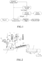
- the apparatus for directly drying inorganic sludge by a drum process comprises: a drum 1 containing a number of steel balls; a slag-sludge conveying device 2 having an inlet end corresponding to an outlet of the drum 1; a slag-sludge separation device 3 having an inlet end corresponding to an outlet of the slag-sludge conveying device 2 and outlets corresponding to different stock bins; a tail gas treatment device 4 having a gas inlet connected to the outlet of the drum 1 through a conveying pipeline; a tail sludge mixing device 5 having an inlet connected to a tail sludge outlet of the tail gas treatment device 4 through a conveying pipeline, wherein an outlet of the tail sludge mixing device 5 is connected to an inlet of the drum 1 through a sludge conveying pipeline and a sludge pump.
- the slag-sludge separation device utilizes a screening process, wherein the hole size of a screen mesh is not more than 0.25 mm (screen mesh number is not less than 60 meshes).
- the present invention employs a hot slag drum treatment process.
- the molten slag and the inorganic sludge are synchronously conveyed to the drum at a specific ratio with a molten slag conveying device and a sludge conveying system respectively.
- the slag and the sludge are fully mixed by the rotation of the drum.
- cold granular slag and dried sludge having the required water content are obtained.
- the apparatus of the present invention can realize rapid, steady and low-cost treatment of slag granulation and sludge drying.
- Metallurgical slag 100 is first continuously conveyed to a rotating drum 1 from a slag pot.
- inorganic sludge is conveyed to the drum 1 at a given flow rate with a sludge conveying device from a place where it is produced.
- the slag and the watercontaining sludge are fully mixed.
- the slag is granulated, and the sludge is dehydrated.
- the sludge 200 is conveyed with a sealed slag-sludge conveying device 2 to a slag-sludge separation device 3 for treatment.
- the separated materials enter different stock bins according to the composition and classification.
- the waste gas generated during the drum drying of the sludge is purified by a tail gas treatment device 4 and discharged when it satisfies the discharge standard.
- the tail sludge generated in the tail gas treatment device 4 is pumped into an inlet of a tail sludge mixing device 5 with a sludge conveying pump, mixed with the sludge generated from a sludge source, agitated uniformly with an agitator, and pumped with a sludge pump at a specified concentration into a sludge conveying pipeline through which it is sent to the drum 1.
- a single drum device treated 180,000 tons of high-temperature steel slag per year.
- OG sludge mud having a water content of 80% was pumped into the drum device.
- the water in the OG sludge mud was used to cool the high-temperature steel slag, while the sensible heat of the steel slag was used to dry the sludge.
- the target water content of the sludge was set to 3%.
- the flow ratio of the slag/sludge fed into the drum was 1.9:1.0. 95,000 tons of OG sludge could be dried every year.
- the slag-sludge (100-130°C) was directly conveyed to a slag-sludge separation device with a conveying device.
- the sludge was dried to a water content of about 3%. The whole process only took 5 minutes.
- the steel slag and the dried sludge were continuously discharged from the lower part of the slag-sludge separation device.
- the granular slag and the sludge powder were sent to different stock bins, waiting for trucks to be delivered to users.
- OG sludge mud having a water content of 70% was pumped into a drum device.
- the water in the OG sludge mud was used to cool the high-temperature steel slag, while the sensible heat of the steel slag was used to dry the sludge.
- the target water content of the sludge was set to 15%.
- the flow ratio of the slag/sludge fed into the drum was 1.5:1.0.
- the slag-sludge 100-130°C
- the sludge was dried to a water content of about 3%. The whole process only took 5 minutes.
- the steel slag and the dried sludge were continuously discharged from the lower part of the slag-sludge separation device. After screening and even spinning, the granular slag and the sludge powder were sent to different stock bins, waiting for trucks to be delivered to users.
- OG sludge mud having a water content of 95% was pumped into a drum device.
- the water in the OG sludge mud was used to cool the high-temperature steel slag, while the sensible heat of the steel slag was used to dry the sludge.
- the target water content of the sludge was set to 3%.
- the flow ratio of the slag/sludge fed into the drum was 3.0:1.0.
- the slag-sludge 100-130°C
- the sludge was dried to a water content of about 3%.
- a batch-wise mode was adopted for feeding, wherein OG sludge mud having a water content of 80% was pumped into a drum device.
- the water in the OG sludge mud was used to cool the high-temperature steel slag, while the sensible heat of the steel slag was used to dry the sludge.
- the target water content of the sludge was set to 3%.
- the mass ratio of the slag/sludge fed into the drum was 1.9:1.0.
- the slag-sludge 100-130°C was directly conveyed to a slag-sludge separation device with a conveying device.
- the sludge was dried to a water content of about 3%. The whole process only took 5 minutes. After full heat exchange in the drum, the steel slag and the dried sludge were continuously discharged from the lower part of the slag-sludge separation device. After screening and even spinning, the granular slag and the sludge powder were sent to different stock bins, waiting for trucks to be delivered to users.
Landscapes
- Engineering & Computer Science (AREA)
- Chemical & Material Sciences (AREA)
- Environmental & Geological Engineering (AREA)
- Chemical Kinetics & Catalysis (AREA)
- General Chemical & Material Sciences (AREA)
- Oil, Petroleum & Natural Gas (AREA)
- Analytical Chemistry (AREA)
- Mechanical Engineering (AREA)
- Organic Chemistry (AREA)
- Health & Medical Sciences (AREA)
- Biomedical Technology (AREA)
- Life Sciences & Earth Sciences (AREA)
- Water Supply & Treatment (AREA)
- Hydrology & Water Resources (AREA)
- General Engineering & Computer Science (AREA)
- Metallurgy (AREA)
- Materials Engineering (AREA)
- Manufacturing & Machinery (AREA)
- Microbiology (AREA)
- Treatment Of Sludge (AREA)
- Processing Of Solid Wastes (AREA)
- Treating Waste Gases (AREA)
- Combined Means For Separation Of Solids (AREA)
- Drying Of Solid Materials (AREA)
Claims (9)
- Verfahren zum Trocknen anorganischen Schlamms mit geschmolzener Schlacke (100) mit folgenden Schritten:Transportieren der geschmolzener Schlacke (100) und des anorganischen Schlamms zu einer Trommel (1), die Stahlkugeln enthält, mit entsprechenden Transportvorrichtungen; Mischen der geschmolzenen Schlacke (100) und des anorganischen Schlamms;und nachdem der Wassergehalt des anorganischen Schlamms auf 3 % bis 15 % verringert wurde, Transportieren einer Mischung (200) der geschmolzenen Schlacke und des trockenen anorganischen Schlamms zu einer Schlacke-Schlamm-Trennvorrichtung (3) mit einer Schlacke-Schlamm-Transportvorrichtung (2), die an einem Auslassende der Trommel positioniert ist, um die geschmolzene Schlacke von dem trockenen anorganischen Schlamm zu trennen;wobei Staub, Sulfide und anorganische Verbindungen, die sich in einem Endgas befinden, das während des Trocknens des anorganischen Schlamms erzeugt wird, von einem Trommelauslass in eine Endgasbehandlungsvorrichtung (4) eintreten, und das Gas abgelassen wird, wenn es den Ablassstandard nach der Behandlung erfüllt;wobei der in der Gasbehandlungsvorrichtung getrennte Staub von einem Endschlammauslass der Endgasbehandlungsvorrichtung in eine Endschlammmischvorrichtung (5) eintritt, sich mit dem zu trocknenden anorganischen Schlamm vermischt und dann durch eine Schlammtransportpipeline zu der Trommel (1) transportiert wird.
- Verfahren zum Trocknen anorganischen Schlamms mit geschmolzener Schlacke (100) nach Anspruch 1, wobei ein Mischmasseverhältnis der geschmolzenen Schlacke (100) zu dem anorganischen Schlamm 1,5-3 beträgt.
- Verfahren zum Trocknen anorganischen Schlamms mit geschmolzener Schlacke (100) nach Anspruch 1, wobei die geschmolzene Schlacke und der trockene anorganische Schlamm durch eine Kombination von Sieben und Drehen getrennt werden.
- Verfahren zum Trocknen anorganischen Schlamms mit geschmolzener Schlacke (100) nach Anspruch 1, wobeider Schritt des Behandelns von Staub, Sulfiden und organischen Verbindungen, die in einem während des Trocknens des anorganischen Schlamms entstandenen Endgas vorhanden sind, durch Nassalkaliwaschen und/oder Aktivkohleadsorption durchgeführt wird;und ferner ein Nasswaschen oder Berieseln des entstehenden Staubs aufweist, wodurch der Staub gebunden wird, Mischen des Staubs mit dem zu trocknenden anorganischen Schlamm, Rühren, und Mischen mit geschmolzener Schlacke (100) für die Trocknungsbehandlung.
- Verfahren zum Trocknen anorganischen Schlamms mit geschmolzener Schlacke (100) nach Anspruch 3, wobei die Schlacke-Schlamm-Trennvorrichtung (3) einen Siebvorgang verwendet, wobei eine Lochgröße eines Siebgitters nicht größer als 0,25 mm ist (eine Siebgitteranzahl ist nicht geringer als 60 Gitter).
- Verfahren zum Trocknen anorganischen Schlamms mit geschmolzener Schlacke (100) nach Anspruch 1, wobei das Mischen und Trocknen in Chargen, durch Fließzugabe oder durch Halbfließzugabe durchgeführt wird.
- Verfahren zum Trocknen anorganischen Schlamms mit geschmolzener Schlacke (100) nach Anspruch 1,wobei der Schritt des Transportierens der geschmolzenen Schlacke (100) und des anorganischen Schlamms zu der Trommel (1) aufweist, dass die Mischung der geschmolzenen Schlacke (100) und des anorganischen Schlamms wärmegetauscht, dehydriert, gekühlt und durch Drehung der Trommel (1) und Rollen der Stahlkugeln zerbrochen wird, wodurch die geschmolzene Schlacke (100) und der anorganische Schlamm gekühlt und getrocknet werden, worauf ein direktes Auslassen folgt;wobei der anorganische Schlamm einen anfänglichen Wassergehalt von 70 % bis 99 % aufweist;wobei ein Schlacke/Schlamm-Strömungsmassenverhältnis der geschmolzenen Schlacke (100) zu dem anorganischen Schlamm 1,5-3,0 beträgt; wobei der anorganische Schlamm eine Strömungsrate von 10t/h-80t/h aufweist;wobei das Trennen der geschmolzenen Schlacke von dem trockenen anorganischen Schlamm eine Kombination an Sieben und Drehen aufweist;wobei ein Trennen des Staubs, der Sulfide und der organischen Verbindungen, die in einem Endgas vorhanden sind, Nassalkaliwaschen und Aktivkohleadsorption aufweist, um den Staub, die Sulfide und die organischen Verbindungen zu behandeln, die in dem Endgas vorhanden sind, woraufhin das Gas abgelassen wird;wobei der in der Endgasbehandlung entstandene Staub nassgewaschen oder berieselt wird, gesammelt wird, und dann mit einer Transportvorrichtung zu einer Endschlammmischvorrichtung transportiert wird, wobei der Staub mit Primärschlamm vermischt wird, gerührt wird, und dann regulär mit einer Schlammpumpe für die Trocknungsbehandlung zu der Trommel (1) transportiert wird, wobei eine Differenz zwischen einem Wassergehalt des Endschlamms nach dem Mischen und Rühren und dem anfänglichen Wassergehalt des anorganischen Schlamms ± 5 % nicht übersteigt.
- Vorrichtung zum direkten Trocknen von anorganischem Schlamm durch einen Trommelvorgang, der das Verfahren zum Trocknen anorganischen Schlamms mit geschmolzener Schlacke nach einem der Ansprüche 1 bis 7 verwendet, wobei die Vorrichtung aufweist:eine Trommel (1), die eine Anzahl an Stahlkugeln enthält;eine Schlacke-Schlamm-Transportvorrichtung (2) mit einem Einlassende, das einem Auslass der Trommel entspricht;eine Schlacke-Schlamm-Trennvorrichtung (3) mit einem Einlassende, das einem Auslass der Schlacke-Schlamm-Transportvorrichtung (2) entspricht, und Auslässen, die unterschiedlichen Lagerplätzen entsprechen;eine Endgasbehandlungsvorrichtung (4) mit einem Gaseinlass, der mit dem Auslass der Trommel (1) durch eine Transportpipeline verbunden ist;eine Endschlammmischvorrichtung (5) mit einem Einlass, der mit einem Endschlammauslass der Endgasbehandlungsvorrichtung (4) durch eine Transportpipeline verbunden ist und dafür ausgelegt ist, einen Staub von der Endgasbehandlungsvorrichtung (4) mit anorganischem Primärschlamm zu mischen;eine Schlammtransportpipeline, die dafür ausgelegt ist, einen Auslass der Endschlammmischvorrichtung (5) mit einem Einlass der Trommel (1) zu verbunden; undeine Schlammpumpe, die zum Pumpen des Schlamms zu der Trommel (1) an der Schlammtransportpipeline angeordnet ist.
- Vorrichtung zum direkten Trocknen anorganischen Schlamms mit einem Trommelvorgang nach Anspruch 8, wobei die Schlacke-Schlamm-Trennvorrichtung (3) einen Siebvorgang verwendet, wobei eine Lochgröße eines Siebgitters nicht größer als 0,25 mm ist (eine Siebgitteranzahl ist nicht geringer als 60 Gitter).
Applications Claiming Priority (2)
| Application Number | Priority Date | Filing Date | Title |
|---|---|---|---|
| CN201811145994.0A CN109293194B (zh) | 2018-09-29 | 2018-09-29 | 一种滚筒法直接干化无机污泥的方法及装置 |
| PCT/CN2019/108152 WO2020063745A1 (zh) | 2018-09-29 | 2019-09-26 | 一种滚筒法直接干化无机污泥的方法及装置 |
Publications (3)
| Publication Number | Publication Date |
|---|---|
| EP3858792A1 EP3858792A1 (de) | 2021-08-04 |
| EP3858792A4 EP3858792A4 (de) | 2021-10-06 |
| EP3858792B1 true EP3858792B1 (de) | 2024-02-07 |
Family
ID=65165021
Family Applications (1)
| Application Number | Title | Priority Date | Filing Date |
|---|---|---|---|
| EP19866463.3A Active EP3858792B1 (de) | 2018-09-29 | 2019-09-26 | Verfahren und vorrichtung zum direkten trocknen von anorganischem schlamm mit einem trommelziehverfahren |
Country Status (7)
| Country | Link |
|---|---|
| US (1) | US11891318B2 (de) |
| EP (1) | EP3858792B1 (de) |
| JP (1) | JP7190560B2 (de) |
| KR (1) | KR102928333B1 (de) |
| CN (1) | CN109293194B (de) |
| TW (1) | TWI815980B (de) |
| WO (1) | WO2020063745A1 (de) |
Families Citing this family (16)
| Publication number | Priority date | Publication date | Assignee | Title |
|---|---|---|---|---|
| CN109293194B (zh) | 2018-09-29 | 2022-07-26 | 宝山钢铁股份有限公司 | 一种滚筒法直接干化无机污泥的方法及装置 |
| CN111253045A (zh) * | 2020-02-01 | 2020-06-09 | 肇庆泉兴生态科技有限公司 | 一种钢渣基城镇污泥脱水剂及其脱水方法 |
| CN114057372B (zh) * | 2020-07-31 | 2023-11-14 | 宝山钢铁股份有限公司 | 有机污泥的滚筒渣余热干化方法 |
| CN114057371B (zh) * | 2020-07-31 | 2023-11-14 | 宝山钢铁股份有限公司 | 一种基于颗粒热源的污泥干化处理方法 |
| CN114058747B (zh) * | 2020-07-31 | 2022-12-16 | 宝山钢铁股份有限公司 | 一种干式粒化熔渣与污泥耦合干化的工艺及装置 |
| CN112094030B (zh) * | 2020-09-17 | 2022-12-13 | 毅康科技有限公司 | 一种污泥干燥破碎处理装置 |
| CN112503856A (zh) * | 2020-12-07 | 2021-03-16 | 张绪祎 | 用湿泥料干燥冷淬液态熔融料的方法 |
| CN112408748A (zh) * | 2020-12-10 | 2021-02-26 | 天津市融泰水务有限公司 | 基于介质加载的快速污泥造粒干化处理系统及处理方法 |
| CN113800731A (zh) * | 2021-09-14 | 2021-12-17 | 蕉岭伟态环保有限责任公司 | 一种城市污泥无害化环保处理系统 |
| CN115253400B (zh) * | 2022-08-08 | 2023-08-11 | 无锡市曜通环保机械有限公司 | 连续式旋流澄清处理设备 |
| US12054795B2 (en) * | 2022-09-22 | 2024-08-06 | Shandong University | System and method for delivering fluidized powder based on flue gas carrying waste slag and instant cooling steel slag |
| CN116920536B (zh) * | 2023-05-11 | 2024-10-11 | 国电环境保护研究院有限公司 | 燃煤烟气和脱硫废水处理装置 |
| CN116481287B (zh) * | 2023-06-25 | 2023-08-18 | 德州斯诺威机械有限公司 | 一种颗粒饲料加工在线烘干装置 |
| CN118545886B (zh) * | 2024-05-28 | 2025-04-01 | 浙江一树纸业集团有限公司 | 一种造纸污泥回用系统及其工艺 |
| CN119533111B (zh) * | 2024-11-27 | 2025-11-04 | 华东理工大学 | 一种用于全物料的含水率自反馈干化的方法及装置 |
| CN120120823B (zh) * | 2025-05-12 | 2025-09-02 | 内蒙古民泽农牧科技有限公司 | 一种有机肥生产加工用原料烘干设备 |
Family Cites Families (26)
| Publication number | Priority date | Publication date | Assignee | Title |
|---|---|---|---|---|
| US3165268A (en) * | 1963-01-08 | 1965-01-12 | Harsco Corp | Method and apparatus for processing ferrous slag |
| US3909410A (en) * | 1973-02-20 | 1975-09-30 | Young W Elmo | Process for treating sewage sludge |
| JPS62294140A (ja) * | 1986-06-11 | 1987-12-21 | Nippon Jiryoku Senko Kk | 製鉄所から発生するスラグの処理方法 |
| US4787323A (en) | 1987-08-12 | 1988-11-29 | Atlantic Richfield Company | Treating sludges and soil materials contaminated with hydrocarbons |
| JPH0741269B2 (ja) * | 1991-08-12 | 1995-05-10 | 日本ケミテック株式会社 | 汚泥からの金属回収方法 |
| TW585924B (en) * | 2002-04-03 | 2004-05-01 | Kobe Steel Ltd | Method for making reduced iron |
| CN1329332C (zh) * | 2004-08-31 | 2007-08-01 | 宝山钢铁股份有限公司 | 滚筒法高粘度熔态炉渣的处理方法 |
| RU2293070C2 (ru) | 2005-04-18 | 2007-02-10 | Василий Михайлович Кнатько | Способ комплексной переработки и утилизации осадков сточных вод |
| KR100685385B1 (ko) * | 2005-10-26 | 2007-02-22 | 이보엠텍 주식회사 | 하, 폐수 슬러지의 자원 재활용 장치 |
| CN100523684C (zh) | 2007-12-14 | 2009-08-05 | 东南大学 | 闭式多室流化床污泥干燥方法 |
| JP2009233563A (ja) | 2008-03-27 | 2009-10-15 | Metawater Co Ltd | 汚泥乾燥機の運転制御方法 |
| CN201327265Y (zh) | 2008-08-22 | 2009-10-14 | 北京中矿环保科技股份有限公司 | 一种干化污泥的系统及相应的热电厂与有污泥产出的系统 |
| CN101885574A (zh) * | 2009-05-14 | 2010-11-17 | 武汉东海石化重型装备有限公司 | 市政污泥热氧化处理成套装备 |
| JP5815209B2 (ja) * | 2010-02-09 | 2015-11-17 | 月島機械株式会社 | 有機性含水廃棄物の乾燥方法及びその設備 |
| US9016477B2 (en) * | 2012-03-19 | 2015-04-28 | Mid-American Gunite, Inc. | Method and system for processing slag material |
| KR101197299B1 (ko) * | 2012-05-08 | 2012-11-05 | (주) 엠엔이엔티 | 폐기물 선별장치 |
| RU2545574C2 (ru) | 2012-11-16 | 2015-04-10 | Федеральное государственное бюджетное образовательное учреждение высшего профессионального образования "Кемеровский государственный университет" | Способ переработки осадков сточных вод |
| CN104512988A (zh) * | 2013-09-29 | 2015-04-15 | 宝山钢铁股份有限公司 | 一种利用不锈钢熔渣处理重金属污泥的方法 |
| KR101729994B1 (ko) * | 2015-10-28 | 2017-04-25 | 주식회사 한미엔텍 | 열매체를 이용한 저온 슬러지 건조장치 및 그 건조방법 |
| CN105399304B (zh) * | 2015-12-25 | 2017-12-01 | 柳建国 | 生物污泥干化和焚烧循环处理方法及其成套设备 |
| CN105731754A (zh) * | 2016-02-24 | 2016-07-06 | 同济大学 | 一种利用炉渣余热干化污泥的处理装置及方法 |
| CN105948459A (zh) * | 2016-05-19 | 2016-09-21 | 山东齐盛机电工程有限公司 | 一种污泥干化焚烧处置方法 |
| CN107557505A (zh) | 2016-06-30 | 2018-01-09 | 宝山钢铁股份有限公司 | 适合全量钢渣处理的滚筒法处理工艺及处理装置 |
| KR101736191B1 (ko) * | 2016-09-01 | 2017-05-16 | 주식회사 한미엔텍 | 자생 그래뉼을 이용한 슬러지 건조장치 및 그 건조방법 |
| RU2666862C1 (ru) | 2017-04-20 | 2018-09-12 | ООО "СтройИнвестТопаз" | Способ обезвреживания механически обезвоженных осадков сточных вод |
| CN109293194B (zh) * | 2018-09-29 | 2022-07-26 | 宝山钢铁股份有限公司 | 一种滚筒法直接干化无机污泥的方法及装置 |
-
2018
- 2018-09-29 CN CN201811145994.0A patent/CN109293194B/zh active Active
-
2019
- 2019-09-26 US US17/278,435 patent/US11891318B2/en active Active
- 2019-09-26 JP JP2021516959A patent/JP7190560B2/ja active Active
- 2019-09-26 WO PCT/CN2019/108152 patent/WO2020063745A1/zh not_active Ceased
- 2019-09-26 KR KR1020217011900A patent/KR102928333B1/ko active Active
- 2019-09-26 EP EP19866463.3A patent/EP3858792B1/de active Active
- 2019-09-27 TW TW108135115A patent/TWI815980B/zh active
Also Published As
| Publication number | Publication date |
|---|---|
| TWI815980B (zh) | 2023-09-21 |
| US20210347665A1 (en) | 2021-11-11 |
| CN109293194B (zh) | 2022-07-26 |
| EP3858792A1 (de) | 2021-08-04 |
| CN109293194A (zh) | 2019-02-01 |
| JP2022501187A (ja) | 2022-01-06 |
| KR102928333B1 (ko) | 2026-02-19 |
| WO2020063745A1 (zh) | 2020-04-02 |
| JP7190560B2 (ja) | 2022-12-15 |
| KR20210059774A (ko) | 2021-05-25 |
| EP3858792A4 (de) | 2021-10-06 |
| BR112021004122A2 (pt) | 2021-05-25 |
| TW202026255A (zh) | 2020-07-16 |
| US11891318B2 (en) | 2024-02-06 |
Similar Documents
| Publication | Publication Date | Title |
|---|---|---|
| US11891318B2 (en) | Method and apparatus for direct drying of inorganic sludge with drum drawing process | |
| WO2013026263A1 (zh) | 脱水污泥再处理方法 | |
| EP4190919B1 (de) | Integriertes trocknungsverfahren und vorrichtung für trockene granulierte schlacke und schlamm | |
| CN112520769B (zh) | 利用水泥厂废烟气及其余热进行赤泥脱碱同时回收氧化铝的工艺及装置 | |
| CN114956618B (zh) | 一种水泥窑协同处置飞灰系统 | |
| CN206783511U (zh) | 一种污泥深度脱水、干化、碳化处理处置系统 | |
| CN110330211A (zh) | 一种高温钢渣与污泥耦合干化的工艺及装置 | |
| CN111994928A (zh) | 一种铝灰回收处理系统及其处理方法 | |
| CN114763262B (zh) | 一种石油焦处理工艺及处理系统 | |
| CN110723961A (zh) | 一种固体废物综合利用制备的环保微孔砖及其制备方法 | |
| TW202227770A (zh) | 一種石油焦處理裝置、方法及處理系統 | |
| CN218395257U (zh) | 一种连续式无害化处置电解锰渣的装置 | |
| CN108455613A (zh) | 电石渣制备活性氧化钙电石原料循环利用方法及其装置 | |
| CN216137437U (zh) | 一种资源化处理垃圾焚烧飞灰的系统 | |
| CN110822453B (zh) | 一种煤矸石综合利用预处理系统及预处理方法 | |
| CN221515585U (zh) | 一种工业废盐热解碳化无害化处置系统 | |
| CN110183122B (zh) | 基于工业余热协同处置固废制备胶凝材料的系统及方法 | |
| RU2800936C2 (ru) | Способ прямого обезвоживания неорганических осадков посредством процесса барабанного типа и устройство для его осуществления | |
| CN114057371B (zh) | 一种基于颗粒热源的污泥干化处理方法 | |
| CN116240038A (zh) | 一种重金属高富集植物耦合污泥制备生物炭的系统及工艺 | |
| BR112021004122B1 (pt) | Método e aparelho para secagem direta de lodo inorgânico com processo de extração por tambor | |
| CN221789068U (zh) | 一种碳酸钠混盐资源化处置装置 | |
| CN210826301U (zh) | 一种黄金冶炼渣综合利用设备系统 | |
| CN114057372B (zh) | 有机污泥的滚筒渣余热干化方法 | |
| CN223268559U (zh) | 一种陶粒生产线 |
Legal Events
| Date | Code | Title | Description |
|---|---|---|---|
| STAA | Information on the status of an ep patent application or granted ep patent |
Free format text: STATUS: THE INTERNATIONAL PUBLICATION HAS BEEN MADE |
|
| PUAI | Public reference made under article 153(3) epc to a published international application that has entered the european phase |
Free format text: ORIGINAL CODE: 0009012 |
|
| STAA | Information on the status of an ep patent application or granted ep patent |
Free format text: STATUS: REQUEST FOR EXAMINATION WAS MADE |
|
| 17P | Request for examination filed |
Effective date: 20210304 |
|
| AK | Designated contracting states |
Kind code of ref document: A1 Designated state(s): AL AT BE BG CH CY CZ DE DK EE ES FI FR GB GR HR HU IE IS IT LI LT LU LV MC MK MT NL NO PL PT RO RS SE SI SK SM TR |
|
| A4 | Supplementary search report drawn up and despatched |
Effective date: 20210908 |
|
| RIC1 | Information provided on ipc code assigned before grant |
Ipc: C02F 103/16 20060101ALN20210902BHEP Ipc: C02F 103/18 20060101ALN20210902BHEP Ipc: B01D 47/06 20060101ALI20210902BHEP Ipc: B01D 53/79 20060101ALI20210902BHEP Ipc: B01D 53/72 20060101ALI20210902BHEP Ipc: B01D 53/52 20060101ALI20210902BHEP Ipc: C21B 3/08 20060101ALI20210902BHEP Ipc: F26B 11/04 20060101ALI20210902BHEP Ipc: C02F 11/13 20190101ALI20210902BHEP Ipc: F26B 3/18 20060101ALI20210902BHEP Ipc: C02F 11/18 20060101ALI20210902BHEP Ipc: C02F 11/12 20190101AFI20210902BHEP |
|
| DAV | Request for validation of the european patent (deleted) | ||
| DAX | Request for extension of the european patent (deleted) | ||
| STAA | Information on the status of an ep patent application or granted ep patent |
Free format text: STATUS: EXAMINATION IS IN PROGRESS |
|
| 17Q | First examination report despatched |
Effective date: 20221007 |
|
| GRAP | Despatch of communication of intention to grant a patent |
Free format text: ORIGINAL CODE: EPIDOSNIGR1 |
|
| STAA | Information on the status of an ep patent application or granted ep patent |
Free format text: STATUS: GRANT OF PATENT IS INTENDED |
|
| RIC1 | Information provided on ipc code assigned before grant |
Ipc: C02F 103/16 20060101ALN20230830BHEP Ipc: C02F 103/18 20060101ALN20230830BHEP Ipc: B01D 53/48 20060101ALI20230830BHEP Ipc: B01D 53/44 20060101ALI20230830BHEP Ipc: F26B 25/00 20060101ALI20230830BHEP Ipc: F26B 3/20 20060101ALI20230830BHEP Ipc: B01D 47/06 20060101ALI20230830BHEP Ipc: B01D 53/79 20060101ALI20230830BHEP Ipc: B01D 53/72 20060101ALI20230830BHEP Ipc: B01D 53/52 20060101ALI20230830BHEP Ipc: C21B 3/08 20060101ALI20230830BHEP Ipc: F26B 11/04 20060101ALI20230830BHEP Ipc: C02F 11/13 20190101ALI20230830BHEP Ipc: F26B 3/18 20060101ALI20230830BHEP Ipc: C02F 11/18 20060101ALI20230830BHEP Ipc: C02F 11/12 20190101AFI20230830BHEP |
|
| INTG | Intention to grant announced |
Effective date: 20230929 |
|
| GRAS | Grant fee paid |
Free format text: ORIGINAL CODE: EPIDOSNIGR3 |
|
| GRAA | (expected) grant |
Free format text: ORIGINAL CODE: 0009210 |
|
| STAA | Information on the status of an ep patent application or granted ep patent |
Free format text: STATUS: THE PATENT HAS BEEN GRANTED |
|
| AK | Designated contracting states |
Kind code of ref document: B1 Designated state(s): AL AT BE BG CH CY CZ DE DK EE ES FI FR GB GR HR HU IE IS IT LI LT LU LV MC MK MT NL NO PL PT RO RS SE SI SK SM TR |
|
| REG | Reference to a national code |
Ref country code: GB Ref legal event code: FG4D |
|
| REG | Reference to a national code |
Ref country code: CH Ref legal event code: EP |
|
| REG | Reference to a national code |
Ref country code: IE Ref legal event code: FG4D |
|
| REG | Reference to a national code |
Ref country code: DE Ref legal event code: R096 Ref document number: 602019046307 Country of ref document: DE |
|
| REG | Reference to a national code |
Ref country code: LT Ref legal event code: MG9D |
|
| REG | Reference to a national code |
Ref country code: NL Ref legal event code: MP Effective date: 20240207 |
|
| PG25 | Lapsed in a contracting state [announced via postgrant information from national office to epo] |
Ref country code: IS Free format text: LAPSE BECAUSE OF FAILURE TO SUBMIT A TRANSLATION OF THE DESCRIPTION OR TO PAY THE FEE WITHIN THE PRESCRIBED TIME-LIMIT Effective date: 20240607 |
|
| PG25 | Lapsed in a contracting state [announced via postgrant information from national office to epo] |
Ref country code: LT Free format text: LAPSE BECAUSE OF FAILURE TO SUBMIT A TRANSLATION OF THE DESCRIPTION OR TO PAY THE FEE WITHIN THE PRESCRIBED TIME-LIMIT Effective date: 20240207 |
|
| PG25 | Lapsed in a contracting state [announced via postgrant information from national office to epo] |
Ref country code: GR Free format text: LAPSE BECAUSE OF FAILURE TO SUBMIT A TRANSLATION OF THE DESCRIPTION OR TO PAY THE FEE WITHIN THE PRESCRIBED TIME-LIMIT Effective date: 20240508 |
|
| REG | Reference to a national code |
Ref country code: AT Ref legal event code: MK05 Ref document number: 1655271 Country of ref document: AT Kind code of ref document: T Effective date: 20240207 |
|
| PG25 | Lapsed in a contracting state [announced via postgrant information from national office to epo] |
Ref country code: HR Free format text: LAPSE BECAUSE OF FAILURE TO SUBMIT A TRANSLATION OF THE DESCRIPTION OR TO PAY THE FEE WITHIN THE PRESCRIBED TIME-LIMIT Effective date: 20240207 Ref country code: RS Free format text: LAPSE BECAUSE OF FAILURE TO SUBMIT A TRANSLATION OF THE DESCRIPTION OR TO PAY THE FEE WITHIN THE PRESCRIBED TIME-LIMIT Effective date: 20240507 Ref country code: NL Free format text: LAPSE BECAUSE OF FAILURE TO SUBMIT A TRANSLATION OF THE DESCRIPTION OR TO PAY THE FEE WITHIN THE PRESCRIBED TIME-LIMIT Effective date: 20240207 |
|
| PG25 | Lapsed in a contracting state [announced via postgrant information from national office to epo] |
Ref country code: ES Free format text: LAPSE BECAUSE OF FAILURE TO SUBMIT A TRANSLATION OF THE DESCRIPTION OR TO PAY THE FEE WITHIN THE PRESCRIBED TIME-LIMIT Effective date: 20240207 |
|
| PG25 | Lapsed in a contracting state [announced via postgrant information from national office to epo] |
Ref country code: AT Free format text: LAPSE BECAUSE OF FAILURE TO SUBMIT A TRANSLATION OF THE DESCRIPTION OR TO PAY THE FEE WITHIN THE PRESCRIBED TIME-LIMIT Effective date: 20240207 |
|
| PG25 | Lapsed in a contracting state [announced via postgrant information from national office to epo] |
Ref country code: RS Free format text: LAPSE BECAUSE OF FAILURE TO SUBMIT A TRANSLATION OF THE DESCRIPTION OR TO PAY THE FEE WITHIN THE PRESCRIBED TIME-LIMIT Effective date: 20240507 Ref country code: NO Free format text: LAPSE BECAUSE OF FAILURE TO SUBMIT A TRANSLATION OF THE DESCRIPTION OR TO PAY THE FEE WITHIN THE PRESCRIBED TIME-LIMIT Effective date: 20240507 Ref country code: NL Free format text: LAPSE BECAUSE OF FAILURE TO SUBMIT A TRANSLATION OF THE DESCRIPTION OR TO PAY THE FEE WITHIN THE PRESCRIBED TIME-LIMIT Effective date: 20240207 Ref country code: LT Free format text: LAPSE BECAUSE OF FAILURE TO SUBMIT A TRANSLATION OF THE DESCRIPTION OR TO PAY THE FEE WITHIN THE PRESCRIBED TIME-LIMIT Effective date: 20240207 Ref country code: IS Free format text: LAPSE BECAUSE OF FAILURE TO SUBMIT A TRANSLATION OF THE DESCRIPTION OR TO PAY THE FEE WITHIN THE PRESCRIBED TIME-LIMIT Effective date: 20240607 Ref country code: HR Free format text: LAPSE BECAUSE OF FAILURE TO SUBMIT A TRANSLATION OF THE DESCRIPTION OR TO PAY THE FEE WITHIN THE PRESCRIBED TIME-LIMIT Effective date: 20240207 Ref country code: GR Free format text: LAPSE BECAUSE OF FAILURE TO SUBMIT A TRANSLATION OF THE DESCRIPTION OR TO PAY THE FEE WITHIN THE PRESCRIBED TIME-LIMIT Effective date: 20240508 Ref country code: FI Free format text: LAPSE BECAUSE OF FAILURE TO SUBMIT A TRANSLATION OF THE DESCRIPTION OR TO PAY THE FEE WITHIN THE PRESCRIBED TIME-LIMIT Effective date: 20240207 Ref country code: ES Free format text: LAPSE BECAUSE OF FAILURE TO SUBMIT A TRANSLATION OF THE DESCRIPTION OR TO PAY THE FEE WITHIN THE PRESCRIBED TIME-LIMIT Effective date: 20240207 Ref country code: BG Free format text: LAPSE BECAUSE OF FAILURE TO SUBMIT A TRANSLATION OF THE DESCRIPTION OR TO PAY THE FEE WITHIN THE PRESCRIBED TIME-LIMIT Effective date: 20240207 Ref country code: AT Free format text: LAPSE BECAUSE OF FAILURE TO SUBMIT A TRANSLATION OF THE DESCRIPTION OR TO PAY THE FEE WITHIN THE PRESCRIBED TIME-LIMIT Effective date: 20240207 |
|
| PG25 | Lapsed in a contracting state [announced via postgrant information from national office to epo] |
Ref country code: PL Free format text: LAPSE BECAUSE OF FAILURE TO SUBMIT A TRANSLATION OF THE DESCRIPTION OR TO PAY THE FEE WITHIN THE PRESCRIBED TIME-LIMIT Effective date: 20240207 Ref country code: PT Free format text: LAPSE BECAUSE OF FAILURE TO SUBMIT A TRANSLATION OF THE DESCRIPTION OR TO PAY THE FEE WITHIN THE PRESCRIBED TIME-LIMIT Effective date: 20240607 |
|
| PG25 | Lapsed in a contracting state [announced via postgrant information from national office to epo] |
Ref country code: SE Free format text: LAPSE BECAUSE OF FAILURE TO SUBMIT A TRANSLATION OF THE DESCRIPTION OR TO PAY THE FEE WITHIN THE PRESCRIBED TIME-LIMIT Effective date: 20240207 Ref country code: PT Free format text: LAPSE BECAUSE OF FAILURE TO SUBMIT A TRANSLATION OF THE DESCRIPTION OR TO PAY THE FEE WITHIN THE PRESCRIBED TIME-LIMIT Effective date: 20240607 Ref country code: PL Free format text: LAPSE BECAUSE OF FAILURE TO SUBMIT A TRANSLATION OF THE DESCRIPTION OR TO PAY THE FEE WITHIN THE PRESCRIBED TIME-LIMIT Effective date: 20240207 Ref country code: LV Free format text: LAPSE BECAUSE OF FAILURE TO SUBMIT A TRANSLATION OF THE DESCRIPTION OR TO PAY THE FEE WITHIN THE PRESCRIBED TIME-LIMIT Effective date: 20240207 |
|
| PG25 | Lapsed in a contracting state [announced via postgrant information from national office to epo] |
Ref country code: DK Free format text: LAPSE BECAUSE OF FAILURE TO SUBMIT A TRANSLATION OF THE DESCRIPTION OR TO PAY THE FEE WITHIN THE PRESCRIBED TIME-LIMIT Effective date: 20240207 |
|
| PG25 | Lapsed in a contracting state [announced via postgrant information from national office to epo] |
Ref country code: SM Free format text: LAPSE BECAUSE OF FAILURE TO SUBMIT A TRANSLATION OF THE DESCRIPTION OR TO PAY THE FEE WITHIN THE PRESCRIBED TIME-LIMIT Effective date: 20240207 |
|
| PG25 | Lapsed in a contracting state [announced via postgrant information from national office to epo] |
Ref country code: CZ Free format text: LAPSE BECAUSE OF FAILURE TO SUBMIT A TRANSLATION OF THE DESCRIPTION OR TO PAY THE FEE WITHIN THE PRESCRIBED TIME-LIMIT Effective date: 20240207 Ref country code: EE Free format text: LAPSE BECAUSE OF FAILURE TO SUBMIT A TRANSLATION OF THE DESCRIPTION OR TO PAY THE FEE WITHIN THE PRESCRIBED TIME-LIMIT Effective date: 20240207 |
|
| PG25 | Lapsed in a contracting state [announced via postgrant information from national office to epo] |
Ref country code: SK Free format text: LAPSE BECAUSE OF FAILURE TO SUBMIT A TRANSLATION OF THE DESCRIPTION OR TO PAY THE FEE WITHIN THE PRESCRIBED TIME-LIMIT Effective date: 20240207 |
|
| PG25 | Lapsed in a contracting state [announced via postgrant information from national office to epo] |
Ref country code: SM Free format text: LAPSE BECAUSE OF FAILURE TO SUBMIT A TRANSLATION OF THE DESCRIPTION OR TO PAY THE FEE WITHIN THE PRESCRIBED TIME-LIMIT Effective date: 20240207 Ref country code: SK Free format text: LAPSE BECAUSE OF FAILURE TO SUBMIT A TRANSLATION OF THE DESCRIPTION OR TO PAY THE FEE WITHIN THE PRESCRIBED TIME-LIMIT Effective date: 20240207 Ref country code: RO Free format text: LAPSE BECAUSE OF FAILURE TO SUBMIT A TRANSLATION OF THE DESCRIPTION OR TO PAY THE FEE WITHIN THE PRESCRIBED TIME-LIMIT Effective date: 20240207 Ref country code: EE Free format text: LAPSE BECAUSE OF FAILURE TO SUBMIT A TRANSLATION OF THE DESCRIPTION OR TO PAY THE FEE WITHIN THE PRESCRIBED TIME-LIMIT Effective date: 20240207 Ref country code: DK Free format text: LAPSE BECAUSE OF FAILURE TO SUBMIT A TRANSLATION OF THE DESCRIPTION OR TO PAY THE FEE WITHIN THE PRESCRIBED TIME-LIMIT Effective date: 20240207 Ref country code: CZ Free format text: LAPSE BECAUSE OF FAILURE TO SUBMIT A TRANSLATION OF THE DESCRIPTION OR TO PAY THE FEE WITHIN THE PRESCRIBED TIME-LIMIT Effective date: 20240207 |
|
| REG | Reference to a national code |
Ref country code: DE Ref legal event code: R097 Ref document number: 602019046307 Country of ref document: DE |
|
| PG25 | Lapsed in a contracting state [announced via postgrant information from national office to epo] |
Ref country code: IT Free format text: LAPSE BECAUSE OF FAILURE TO SUBMIT A TRANSLATION OF THE DESCRIPTION OR TO PAY THE FEE WITHIN THE PRESCRIBED TIME-LIMIT Effective date: 20240207 |
|
| PLBE | No opposition filed within time limit |
Free format text: ORIGINAL CODE: 0009261 |
|
| STAA | Information on the status of an ep patent application or granted ep patent |
Free format text: STATUS: NO OPPOSITION FILED WITHIN TIME LIMIT |
|
| PG25 | Lapsed in a contracting state [announced via postgrant information from national office to epo] |
Ref country code: IT Free format text: LAPSE BECAUSE OF FAILURE TO SUBMIT A TRANSLATION OF THE DESCRIPTION OR TO PAY THE FEE WITHIN THE PRESCRIBED TIME-LIMIT Effective date: 20240207 |
|
| 26N | No opposition filed |
Effective date: 20241108 |
|
| REG | Reference to a national code |
Ref country code: DE Ref legal event code: R119 Ref document number: 602019046307 Country of ref document: DE |
|
| PG25 | Lapsed in a contracting state [announced via postgrant information from national office to epo] |
Ref country code: SI Free format text: LAPSE BECAUSE OF FAILURE TO SUBMIT A TRANSLATION OF THE DESCRIPTION OR TO PAY THE FEE WITHIN THE PRESCRIBED TIME-LIMIT Effective date: 20240207 Ref country code: MC Free format text: LAPSE BECAUSE OF FAILURE TO SUBMIT A TRANSLATION OF THE DESCRIPTION OR TO PAY THE FEE WITHIN THE PRESCRIBED TIME-LIMIT Effective date: 20240207 |
|
| REG | Reference to a national code |
Ref country code: CH Ref legal event code: PL |
|
| PG25 | Lapsed in a contracting state [announced via postgrant information from national office to epo] |
Ref country code: LU Free format text: LAPSE BECAUSE OF NON-PAYMENT OF DUE FEES Effective date: 20240926 |
|
| PG25 | Lapsed in a contracting state [announced via postgrant information from national office to epo] |
Ref country code: DE Free format text: LAPSE BECAUSE OF NON-PAYMENT OF DUE FEES Effective date: 20250401 |
|
| REG | Reference to a national code |
Ref country code: BE Ref legal event code: MM Effective date: 20240930 |
|
| PG25 | Lapsed in a contracting state [announced via postgrant information from national office to epo] |
Ref country code: BE Free format text: LAPSE BECAUSE OF NON-PAYMENT OF DUE FEES Effective date: 20240930 |
|
| PG25 | Lapsed in a contracting state [announced via postgrant information from national office to epo] |
Ref country code: FR Free format text: LAPSE BECAUSE OF NON-PAYMENT OF DUE FEES Effective date: 20240930 |
|
| PG25 | Lapsed in a contracting state [announced via postgrant information from national office to epo] |
Ref country code: CH Free format text: LAPSE BECAUSE OF NON-PAYMENT OF DUE FEES Effective date: 20240930 |
|
| PG25 | Lapsed in a contracting state [announced via postgrant information from national office to epo] |
Ref country code: IE Free format text: LAPSE BECAUSE OF NON-PAYMENT OF DUE FEES Effective date: 20240926 |
|
| PGFP | Annual fee paid to national office [announced via postgrant information from national office to epo] |
Ref country code: TR Payment date: 20250908 Year of fee payment: 7 |
|
| PGFP | Annual fee paid to national office [announced via postgrant information from national office to epo] |
Ref country code: GB Payment date: 20250905 Year of fee payment: 7 |
|
| PG25 | Lapsed in a contracting state [announced via postgrant information from national office to epo] |
Ref country code: CY Free format text: LAPSE BECAUSE OF FAILURE TO SUBMIT A TRANSLATION OF THE DESCRIPTION OR TO PAY THE FEE WITHIN THE PRESCRIBED TIME-LIMIT; INVALID AB INITIO Effective date: 20190926 |
|
| PG25 | Lapsed in a contracting state [announced via postgrant information from national office to epo] |
Ref country code: HU Free format text: LAPSE BECAUSE OF FAILURE TO SUBMIT A TRANSLATION OF THE DESCRIPTION OR TO PAY THE FEE WITHIN THE PRESCRIBED TIME-LIMIT; INVALID AB INITIO Effective date: 20190926 |