EP3852933B1 - Steuerverfahren einer reinigungsvorrichtung mit schwerteil-abscheider - Google Patents
Steuerverfahren einer reinigungsvorrichtung mit schwerteil-abscheider Download PDFInfo
- Publication number
- EP3852933B1 EP3852933B1 EP19752177.6A EP19752177A EP3852933B1 EP 3852933 B1 EP3852933 B1 EP 3852933B1 EP 19752177 A EP19752177 A EP 19752177A EP 3852933 B1 EP3852933 B1 EP 3852933B1
- Authority
- EP
- European Patent Office
- Prior art keywords
- chamber
- control method
- reject
- suspension
- heavy
- Prior art date
- Legal status (The legal status is an assumption and is not a legal conclusion. Google has not performed a legal analysis and makes no representation as to the accuracy of the status listed.)
- Active
Links
Images

Classifications
-
- B—PERFORMING OPERATIONS; TRANSPORTING
- B04—CENTRIFUGAL APPARATUS OR MACHINES FOR CARRYING-OUT PHYSICAL OR CHEMICAL PROCESSES
- B04C—APPARATUS USING FREE VORTEX FLOW, e.g. CYCLONES
- B04C5/00—Apparatus in which the axial direction of the vortex is reversed
- B04C5/14—Construction of the underflow ducting; Apex constructions; Discharge arrangements ; discharge through sidewall provided with a few slits or perforations
- B04C5/15—Construction of the underflow ducting; Apex constructions; Discharge arrangements ; discharge through sidewall provided with a few slits or perforations with swinging flaps or revolving sluices; Sluices; Check-valves
-
- B—PERFORMING OPERATIONS; TRANSPORTING
- B01—PHYSICAL OR CHEMICAL PROCESSES OR APPARATUS IN GENERAL
- B01D—SEPARATION
- B01D21/00—Separation of suspended solid particles from liquids by sedimentation
- B01D21/24—Feed or discharge mechanisms for settling tanks
- B01D21/245—Discharge mechanisms for the sediments
- B01D21/2472—Means for fluidising the sediments, e.g. by jets or mechanical agitators
-
- B—PERFORMING OPERATIONS; TRANSPORTING
- B01—PHYSICAL OR CHEMICAL PROCESSES OR APPARATUS IN GENERAL
- B01D—SEPARATION
- B01D21/00—Separation of suspended solid particles from liquids by sedimentation
- B01D21/26—Separation of sediment aided by centrifugal force or centripetal force
- B01D21/267—Separation of sediment aided by centrifugal force or centripetal force by using a cyclone
-
- B—PERFORMING OPERATIONS; TRANSPORTING
- B01—PHYSICAL OR CHEMICAL PROCESSES OR APPARATUS IN GENERAL
- B01D—SEPARATION
- B01D21/00—Separation of suspended solid particles from liquids by sedimentation
- B01D21/30—Control equipment
- B01D21/32—Density control of clear liquid or sediment, e.g. optical control ; Control of physical properties
-
- B—PERFORMING OPERATIONS; TRANSPORTING
- B04—CENTRIFUGAL APPARATUS OR MACHINES FOR CARRYING-OUT PHYSICAL OR CHEMICAL PROCESSES
- B04C—APPARATUS USING FREE VORTEX FLOW, e.g. CYCLONES
- B04C5/00—Apparatus in which the axial direction of the vortex is reversed
- B04C5/14—Construction of the underflow ducting; Apex constructions; Discharge arrangements ; discharge through sidewall provided with a few slits or perforations
- B04C5/18—Construction of the underflow ducting; Apex constructions; Discharge arrangements ; discharge through sidewall provided with a few slits or perforations with auxiliary fluid assisting discharge
-
- D—TEXTILES; PAPER
- D21—PAPER-MAKING; PRODUCTION OF CELLULOSE
- D21D—TREATMENT OF THE MATERIALS BEFORE PASSING TO THE PAPER-MAKING MACHINE
- D21D5/00—Purification of the pulp suspension by mechanical means; Apparatus therefor
- D21D5/18—Purification of the pulp suspension by mechanical means; Apparatus therefor with the aid of centrifugal force
- D21D5/24—Purification of the pulp suspension by mechanical means; Apparatus therefor with the aid of centrifugal force in cyclones
Definitions
- the invention relates to a control method of a device for cleaning a suspension, which has at least one chamber for the suspension and a heavy part separator connected thereto.
- Hydrocyclones are well suited to use centrifugal forces to concentrate heavy parts and light parts in suspensions, especially in fiber suspensions, and to discharge them via the outlet or the separator.
- the heavy parts are separated via sedimentation under the influence of weight.
- a device for separating solid particles from a slurry with a cyclone separator through which the slurry liquid flows is known.
- the cyclone separator is designed with a cylindrical feed area, which has a feed device that opens tangentially into the jacket of the cylindrical feed area, with a jacket section that tapers conically towards an underflow-side discharge area for enriched slurry, and with an overflow-side outflow area for the cleaned slurry.
- a valve for the enriched slurry is connected to the discharge area (4) on the underflow side. The valve is preceded by a sensor that measures the density of the enriched slurry. Possible sensors include an ultrasonic sensor or a optical sensor is provided, through which the transmitted or reflected light is detected with a light detector.
- From the DE102010027680B4 is a method for scanning the underflow jet of a hydrocyclone, in particular for controlling it by detecting the jet change on the coarse grain discharge by optical means.
- the beam is imaged on an opto-electronic image recording device, in particular a camera, by means of a transmitted light illumination device. This determines changes in the optical transparency of the beam and/or a changing beam angle.
- the object of the invention is to optimize the separation of heavy parts.
- the object was achieved in that in the area of the heavy part separator the degree of turbulence and/or the extent of the contaminant load and/or the dumping height is optically recorded and taken into account when controlling the device. With this optical recording, the change in position of individual particles over time or certain time intervals is evaluated on the basis of images.
- the loading and emptying of the heavy part separator can be controlled using the appropriate actuators.
- the degree of turbulence is determined by evaluating the speed of individual particles in the suspension and/or the extent of the contaminant load is determined by evaluating the density of the particles in the suspension and/or the dump height in the heavy particle separator is determined by evaluating the ratio between the number of particles resting and moving particles are recorded.
- dilution liquid is passed into the suspension in the area of the heavy part separator and/or a section of the chamber in front of it.
- the amount of dilution liquid supplied should be controlled depending on the degree of turbulence and/or the extent of the disruptive load.
- the substances or parts removed from the suspension are collected in the heavy-parts separator and can be removed from this closed system using a heavy-parts lock.
- the heavy-parts separator has a first and a second controllable slide, between which there is a reject space.
- the reject space continuously fills with the waste to be removed.
- the actual discharge takes place by closing the first slide and opening the second slide to remove the rejects, whereby the contents in the reject space can be emptied. As a rule, this falls out of the reject space due to its weight; but it can also be vacuumed or rinsed out. This removal usually takes place automatically using a clock control.
- the control of the slides and thus also the cycle time should be controlled depending on the extent of the disruptive load and/or the dump height in the reject space.
- the slides are also protected because of the generally longer cycle time.
- At least one light source and at least one camera should be arranged on at least one side of the reject space.
- the wall of the reject space is partially translucent and the light source and/or the camera are arranged outside the reject space.
- the light source and the camera should be arranged outside the reject space opposite the translucent section of the wall of the reject space and there should be a partition between the light source and the camera that extends as far as the wall of the reject space.
- the application of the invention is particularly advantageous in hydrocyclones. These have a chamber with a circular cross-section, into which an inlet and a light parts outlet open at one end and a heavy parts separator opens at the opposite end.
- the fibrous suspension is generally brought into a circular path by blowing tangentially over the inlet in the chamber, with the fibrous suspension being pressed against the wall of the chamber due to the centrifugal force.
- the fiber suspension moves in a spiral from the inlet towards the heavy part separator.
- the chamber should be conical at least in sections, with the diameter of the chamber decreasing towards the heavy part separator. Reducing the diameter leads to an increase in the rotation speed and thus to an increase in centrifugal and centrifugal forces. This causes the heavy particles to be pressed against the wall of the chamber and concentrated there. At the end of the chamber, the heavy parts can then be removed via the separator.
- a preferably tubular light part outlet running along the center axis should protrude into the center of the chamber at the inlet end of the chamber.
- the light parts of the suspension can be pumped out via this outlet.
- At least one supply line for dilution liquid opens into the chamber.
- the invention can also be used in a sedimentation tank with an inlet and a similarly constructed heavy-parts lock.
- This invention also offers advantages in terms of fiber loss when treating the fiber suspension in the form of wastewater resulting from this manufacturing process.
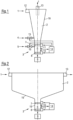
- the device shown in the form of a hydrocyclone is used to clean a fiber suspension 1 of a stock preparation system of a paper machine with a stock density between 1.5 and 3.5% of heavy parts.
- the fixed housing of the hydrocyclone encloses an elongated chamber 2 with a circular cross section.
- an inlet 12 through which the fibrous suspension 1 to be cleaned is injected tangentially.
- the fibrous suspension 1 is brought onto a circular path, with the suspension 1 being pressed against the wall 19 of the chamber 2.
- the fibrous suspension 1 present in the middle of the chamber 2 and cleaned of the heavy parts is pumped out as a light part component via the light part outlet 13.
- a tubular lightweight part outlet 13 at the inlet end along the center axis into the middle of the chamber 2 is sufficient.
- a conical hydrocyclone section adjoins the inlet 12 in the direction of the heavy part separator 3, in which the diameter of the chamber 2 decreases continuously towards the separator 3.
- This taper causes the rotation speed of the suspension 1 to increase in such a way that the heavy particles concentrate on the wall 19 of the chamber 2.
- the suspension 1 enters the chamber 2 of the sedimentation tank via an inlet 12. Because of the higher weight, the heavy parts sink to the bottom of the chamber 2 and collect there in a depression in the floor, which leads to the heavy part separator 3. Here too, the heavy parts are directed from the heavy part separator 3 to the reject discharge 9.
- the fluid cleaned in this way can then be discharged via the light parts outlet 13.
- the heavy part separator 3 has a reject space 6, which is delimited by two controllable slides 7,8. While one slide 7 points towards the chamber 2 of the cleaning device, the other slide 8 is directed towards the reject removal 9.
- the slide 7 to the chamber 2 is open and the slide 8 to the reject removal 9 is closed. If enough reject has accumulated in the reject chamber 6, it is emptied by closing the slide 7 to the chamber 2 and then opening the slide 8 to the reject discharge 9.
- dilution liquid 4 is passed into the suspension 1 via a valve 15 into a section of the chamber 2 located directly in front of the heavy part separator 3.
- This dilution liquid 4 can be injected tangentially or counter to the direction of the rotational flow of the suspension 1 in the chamber 2, whereby the rotational flow can also be influenced to avoid high levels of wear.
- the amount of dilution liquid 4.5 supplied is regulated by the control device 14 via a corresponding control of the valves 15,16.
- the control device 14 uses information about the degree of turbulence and/or the amount of interference in the reject space 6. It should also be taken into account here that too much dilution liquid 4.5 reject can flush back into the chamber 2, which reduces the separation performance.
- dilution can also take place in front of the heavy part separator 3 or in the reject space 6 of the same and can be controlled in the same way as in the hydrocyclone. In general, this is to avoid blockages.
- the parameters of the heavy part separator 3 are optically recorded with regard to the degree of turbulence, the extent of the contaminant load and the dumping height.
- the wall 19 of the reject space 6 has a sight glass 18, to which a light source 10 and a camera 11 outside the reject space 6 are assigned.
- the light source 10 in the form of several LEDs runs in a ring around the camera 11. This ensures uniform illumination.
- the measurement data is transmitted from this camera 11 to the control device 14 and evaluated there.
- the degree of turbulence is determined by evaluating the speed of the particles in the reject space 6, the extent of the contaminant load is determined by evaluating the density of the particles in the reject space 6 and the dumping height in the reject space of the heavy part separator 3 is determined by evaluating the relationship between the number of stationary and detected by moving particles.
Landscapes
- Chemical & Material Sciences (AREA)
- Chemical Kinetics & Catalysis (AREA)
- Engineering & Computer Science (AREA)
- Mechanical Engineering (AREA)
- Separation Of Solids By Using Liquids Or Pneumatic Power (AREA)
- Centrifugal Separators (AREA)
- Paper (AREA)
Applications Claiming Priority (2)
| Application Number | Priority Date | Filing Date | Title |
|---|---|---|---|
| DE102018122808.2A DE102018122808A1 (de) | 2018-09-18 | 2018-09-18 | Steuerverfahren einer Reinigungsvorrichtung mit Schwerteil-Abscheider |
| PCT/EP2019/071214 WO2020057851A1 (de) | 2018-09-18 | 2019-08-07 | Steuerverfahren einer reinigungsvorrichtung mit schwerteil-abscheider |
Publications (3)
| Publication Number | Publication Date |
|---|---|
| EP3852933A1 EP3852933A1 (de) | 2021-07-28 |
| EP3852933B1 true EP3852933B1 (de) | 2023-10-11 |
| EP3852933C0 EP3852933C0 (de) | 2023-10-11 |
Family
ID=67551554
Family Applications (1)
| Application Number | Title | Priority Date | Filing Date |
|---|---|---|---|
| EP19752177.6A Active EP3852933B1 (de) | 2018-09-18 | 2019-08-07 | Steuerverfahren einer reinigungsvorrichtung mit schwerteil-abscheider |
Country Status (6)
| Country | Link |
|---|---|
| EP (1) | EP3852933B1 (pl) |
| CN (1) | CN112714675B (pl) |
| DE (1) | DE102018122808A1 (pl) |
| ES (1) | ES2964543T3 (pl) |
| PL (1) | PL3852933T3 (pl) |
| WO (1) | WO2020057851A1 (pl) |
Family Cites Families (20)
| Publication number | Priority date | Publication date | Assignee | Title |
|---|---|---|---|---|
| DE3211865C2 (de) * | 1982-03-31 | 1987-03-26 | Gewerkschaft Auguste Victoria, 4370 Marl | Trübeentwässerungsvorrichtung |
| GB8327218D0 (en) * | 1983-10-12 | 1983-11-16 | Beloit Corp | Reject handling in cyclones &c |
| DE3904960A1 (de) * | 1989-02-18 | 1990-08-23 | Finckh Maschf | Geraet zum sortieren und entstippen von fasersuspensionen |
| CH677327A5 (pl) * | 1989-07-28 | 1991-05-15 | Buehler Ag | |
| NL1014410C1 (nl) * | 1999-06-21 | 2000-12-22 | Hovex Bv | Scheidingsinrichting, separatie-eenheid voor een dergelijke scheidingsinrichting, en scheidingswerkwijze. |
| ATE267909T1 (de) | 1999-07-06 | 2004-06-15 | Voith Paper Patent Gmbh | Verfahren und vorrichtung zum ausbringen von störstoffen aus einem hydrozyklon |
| JP4180563B2 (ja) * | 2004-12-22 | 2008-11-12 | 株式会社 小川環境研究所 | 沈殿分離操作測定管理方法及び装置 |
| DE202005003105U1 (de) * | 2005-02-25 | 2005-05-12 | Voith Paper Patent Gmbh | Vorrichtung zum Austragen von Schwerteilen aus einem Apparat zur Behandlung einer Faserstoffsuspension, insbesondere aus einem zum Reinigen einer Faserstoffsuspension betreibbaren Hydrozyklon |
| SE529771C2 (sv) * | 2005-04-29 | 2007-11-20 | Gl & V Man Hungary Kft Hermina | Hydrocyklonenhet och metod för separering av en fibermassasuspension innehållande relativt tunga föroreningar |
| FI122973B (fi) * | 2005-06-17 | 2012-09-28 | Metso Paper Inc | Flotaatiokennon injektori, flotaatiokennon injektorin suutinosa ja menetelmä kuitususpensiovirtauksen ja ilman sekoittamiseksi toisiinsa flotaatiokennon injektorissa |
| CN100415338C (zh) * | 2007-06-01 | 2008-09-03 | 华电水处理技术工程有限公司 | 循环冷却水或城镇二级污水的净化方法及设备 |
| JP4968743B2 (ja) * | 2008-02-15 | 2012-07-04 | 三菱重工環境・化学エンジニアリング株式会社 | 液体分級装置、及び、閉塞検出方法 |
| AT506940B1 (de) * | 2008-12-12 | 2010-01-15 | Abz Zierler Ges M B H & Co Kg | Vorrichtung zum abscheiden von feststoffteilchen aus einer trübe |
| JP2010142894A (ja) * | 2008-12-18 | 2010-07-01 | Teral Inc | 液体サイクロン装置 |
| SE535959C2 (sv) * | 2010-01-29 | 2013-03-05 | Alfa Laval Corp Ab | System innefattande centrifugalseparator samt metod för kontroll av detsamma |
| DE102010027680B4 (de) * | 2010-06-16 | 2012-03-22 | Akw Apparate + Verfahren Gmbh | Verfahren zum Abtasten des Unterlaufstrahles eines Hydrozyklons |
| CN203755075U (zh) * | 2013-10-25 | 2014-08-06 | 福伊特造纸(中国)有限公司 | 一种旋流式纸浆除渣器 |
| CN104549794A (zh) * | 2014-12-23 | 2015-04-29 | 中国石油天然气股份有限公司 | 水力旋流器底流控制装置 |
| CN106238234B (zh) * | 2016-10-14 | 2018-08-21 | 大连碧蓝节能环保科技有限公司 | 并联调节式旋液分离器 |
| DE102016122225B4 (de) * | 2016-11-18 | 2018-11-08 | Voith Patent Gmbh | Hydrozyklonanordnung |
-
2018
- 2018-09-18 DE DE102018122808.2A patent/DE102018122808A1/de not_active Ceased
-
2019
- 2019-08-07 PL PL19752177.6T patent/PL3852933T3/pl unknown
- 2019-08-07 WO PCT/EP2019/071214 patent/WO2020057851A1/de not_active Ceased
- 2019-08-07 CN CN201980060808.XA patent/CN112714675B/zh active Active
- 2019-08-07 EP EP19752177.6A patent/EP3852933B1/de active Active
- 2019-08-07 ES ES19752177T patent/ES2964543T3/es active Active
Also Published As
| Publication number | Publication date |
|---|---|
| WO2020057851A1 (de) | 2020-03-26 |
| EP3852933C0 (de) | 2023-10-11 |
| DE102018122808A1 (de) | 2020-03-19 |
| ES2964543T3 (es) | 2024-04-08 |
| EP3852933A1 (de) | 2021-07-28 |
| CN112714675B (zh) | 2023-04-07 |
| PL3852933T3 (pl) | 2024-02-19 |
| CN112714675A (zh) | 2021-04-27 |
Similar Documents
| Publication | Publication Date | Title |
|---|---|---|
| AT511837B1 (de) | Hydrozyklon mit feinstoffabreicherung im zyklonunterlauf | |
| EP2049222B1 (de) | Filtervorrichtung | |
| DE3030980A1 (de) | Hydrozyklon. | |
| WO2011076660A1 (de) | Verfahren und siebvorrichtung zum sieben einer faserstoffsuspension | |
| EP1215335B1 (de) | Drucksortierer zum Entfernen von Störstoffen aus einer störstoffhaltigen Papierfasersuspension | |
| AT510253B1 (de) | Zweistufige pulpensiebvorrichtung mit zwei stationären zylindrischen sieben | |
| DE102004051327B4 (de) | Verfahren zur Entgasung und Zuführung einer Faserstoffsuspension zu einem Stoffauflauf sowie Entgasungsvorrichtung | |
| DE69217081T2 (de) | Hydrozyklon mit turbulenz erzeugenden mitteln | |
| EP3852933B1 (de) | Steuerverfahren einer reinigungsvorrichtung mit schwerteil-abscheider | |
| DE69611732T3 (de) | Siebvorrichtung | |
| EP1860231A2 (de) | Verfahren und Vorrichtung zum Reiningen von störstoffhaltingen Papierrohstoffen | |
| AT408770B (de) | Sortierer zur reinigung einer faserstoffsuspension | |
| EP1598477B1 (de) | Drucksortierer zum Sieben einer Faserstoffsuspension | |
| EP1830001A2 (de) | Vorrichtung zum Austragen von Schwerteilen aus einem Apparat zur Behandlung einer Faserstoffsuspension, insbes. aus einem zum Reinigen einer Faserstoffsuspension betreibbaren Hydrozyklon | |
| DE102021112389A1 (de) | Mehrstufige Sortiervorrichtung | |
| EP1876289B1 (de) | Verfahren zur Abscheidung von Verunreinigungen aus einer Faserstoffsuspension | |
| DE1442501A1 (de) | Verfahren zum Ausscheiden von Fremdkoerpern aus einem fliessfaehigen Medium mittels eines Zyklons und Zyklon zur Ausuebung des Verfahrens | |
| EP1262594B1 (de) | Verfahren zur Abscheidung von Anteilen aus einer Faserstoffsuspension | |
| AT506940B1 (de) | Vorrichtung zum abscheiden von feststoffteilchen aus einer trübe | |
| DE102004039712B4 (de) | Verfahren zum dosierten Transport einer störstoffhaltigen Suspension durch einen einstellbaren Drosselschieber | |
| DE19748233A1 (de) | Filtervorrichtung für Feststoffe, insbesondere Grobschmutz, aufweisendes Abwasser | |
| EP1710347A1 (de) | Verfahren zum Auflösen und Reinigen von störstoffhaltigen Papierrohstoffen | |
| AT16830U1 (de) | Ausschleuseeinrichtung | |
| DE1442501C (de) | Hydrocyklon | |
| EP3398671A1 (de) | Vorrichtung zur trennung von festteilchen aus suspensionen |
Legal Events
| Date | Code | Title | Description |
|---|---|---|---|
| STAA | Information on the status of an ep patent application or granted ep patent |
Free format text: STATUS: UNKNOWN |
|
| STAA | Information on the status of an ep patent application or granted ep patent |
Free format text: STATUS: THE INTERNATIONAL PUBLICATION HAS BEEN MADE |
|
| PUAI | Public reference made under article 153(3) epc to a published international application that has entered the european phase |
Free format text: ORIGINAL CODE: 0009012 |
|
| STAA | Information on the status of an ep patent application or granted ep patent |
Free format text: STATUS: REQUEST FOR EXAMINATION WAS MADE |
|
| 17P | Request for examination filed |
Effective date: 20210419 |
|
| AK | Designated contracting states |
Kind code of ref document: A1 Designated state(s): AL AT BE BG CH CY CZ DE DK EE ES FI FR GB GR HR HU IE IS IT LI LT LU LV MC MK MT NL NO PL PT RO RS SE SI SK SM TR |
|
| DAV | Request for validation of the european patent (deleted) | ||
| DAX | Request for extension of the european patent (deleted) | ||
| GRAP | Despatch of communication of intention to grant a patent |
Free format text: ORIGINAL CODE: EPIDOSNIGR1 |
|
| STAA | Information on the status of an ep patent application or granted ep patent |
Free format text: STATUS: GRANT OF PATENT IS INTENDED |
|
| INTG | Intention to grant announced |
Effective date: 20230509 |
|
| GRAS | Grant fee paid |
Free format text: ORIGINAL CODE: EPIDOSNIGR3 |
|
| GRAA | (expected) grant |
Free format text: ORIGINAL CODE: 0009210 |
|
| STAA | Information on the status of an ep patent application or granted ep patent |
Free format text: STATUS: THE PATENT HAS BEEN GRANTED |
|
| AK | Designated contracting states |
Kind code of ref document: B1 Designated state(s): AL AT BE BG CH CY CZ DE DK EE ES FI FR GB GR HR HU IE IS IT LI LT LU LV MC MK MT NL NO PL PT RO RS SE SI SK SM TR |
|
| REG | Reference to a national code |
Ref country code: GB Ref legal event code: FG4D Free format text: NOT ENGLISH |
|
| REG | Reference to a national code |
Ref country code: CH Ref legal event code: EP |
|
| REG | Reference to a national code |
Ref country code: DE Ref legal event code: R096 Ref document number: 502019009652 Country of ref document: DE |
|
| REG | Reference to a national code |
Ref country code: IE Ref legal event code: FG4D Free format text: LANGUAGE OF EP DOCUMENT: GERMAN |
|
| U01 | Request for unitary effect filed |
Effective date: 20231011 |
|
| U07 | Unitary effect registered |
Designated state(s): AT BE BG DE DK EE FI FR IT LT LU LV MT NL PT SE SI Effective date: 20231017 |
|
| PG25 | Lapsed in a contracting state [announced via postgrant information from national office to epo] |
Ref country code: GR Free format text: LAPSE BECAUSE OF FAILURE TO SUBMIT A TRANSLATION OF THE DESCRIPTION OR TO PAY THE FEE WITHIN THE PRESCRIBED TIME-LIMIT Effective date: 20240112 |
|
| REG | Reference to a national code |
Ref country code: ES Ref legal event code: FG2A Ref document number: 2964543 Country of ref document: ES Kind code of ref document: T3 Effective date: 20240408 |
|
| PG25 | Lapsed in a contracting state [announced via postgrant information from national office to epo] |
Ref country code: IS Free format text: LAPSE BECAUSE OF FAILURE TO SUBMIT A TRANSLATION OF THE DESCRIPTION OR TO PAY THE FEE WITHIN THE PRESCRIBED TIME-LIMIT Effective date: 20240211 |
|
| PG25 | Lapsed in a contracting state [announced via postgrant information from national office to epo] |
Ref country code: IS Free format text: LAPSE BECAUSE OF FAILURE TO SUBMIT A TRANSLATION OF THE DESCRIPTION OR TO PAY THE FEE WITHIN THE PRESCRIBED TIME-LIMIT Effective date: 20240211 Ref country code: GR Free format text: LAPSE BECAUSE OF FAILURE TO SUBMIT A TRANSLATION OF THE DESCRIPTION OR TO PAY THE FEE WITHIN THE PRESCRIBED TIME-LIMIT Effective date: 20240112 |
|
| PG25 | Lapsed in a contracting state [announced via postgrant information from national office to epo] |
Ref country code: RS Free format text: LAPSE BECAUSE OF FAILURE TO SUBMIT A TRANSLATION OF THE DESCRIPTION OR TO PAY THE FEE WITHIN THE PRESCRIBED TIME-LIMIT Effective date: 20231011 Ref country code: NO Free format text: LAPSE BECAUSE OF FAILURE TO SUBMIT A TRANSLATION OF THE DESCRIPTION OR TO PAY THE FEE WITHIN THE PRESCRIBED TIME-LIMIT Effective date: 20240111 Ref country code: HR Free format text: LAPSE BECAUSE OF FAILURE TO SUBMIT A TRANSLATION OF THE DESCRIPTION OR TO PAY THE FEE WITHIN THE PRESCRIBED TIME-LIMIT Effective date: 20231011 |
|
| REG | Reference to a national code |
Ref country code: DE Ref legal event code: R097 Ref document number: 502019009652 Country of ref document: DE |
|
| PG25 | Lapsed in a contracting state [announced via postgrant information from national office to epo] |
Ref country code: CZ Free format text: LAPSE BECAUSE OF FAILURE TO SUBMIT A TRANSLATION OF THE DESCRIPTION OR TO PAY THE FEE WITHIN THE PRESCRIBED TIME-LIMIT Effective date: 20231011 |
|
| PG25 | Lapsed in a contracting state [announced via postgrant information from national office to epo] |
Ref country code: SK Free format text: LAPSE BECAUSE OF FAILURE TO SUBMIT A TRANSLATION OF THE DESCRIPTION OR TO PAY THE FEE WITHIN THE PRESCRIBED TIME-LIMIT Effective date: 20231011 |
|
| PG25 | Lapsed in a contracting state [announced via postgrant information from national office to epo] |
Ref country code: SM Free format text: LAPSE BECAUSE OF FAILURE TO SUBMIT A TRANSLATION OF THE DESCRIPTION OR TO PAY THE FEE WITHIN THE PRESCRIBED TIME-LIMIT Effective date: 20231011 Ref country code: SK Free format text: LAPSE BECAUSE OF FAILURE TO SUBMIT A TRANSLATION OF THE DESCRIPTION OR TO PAY THE FEE WITHIN THE PRESCRIBED TIME-LIMIT Effective date: 20231011 Ref country code: RO Free format text: LAPSE BECAUSE OF FAILURE TO SUBMIT A TRANSLATION OF THE DESCRIPTION OR TO PAY THE FEE WITHIN THE PRESCRIBED TIME-LIMIT Effective date: 20231011 Ref country code: CZ Free format text: LAPSE BECAUSE OF FAILURE TO SUBMIT A TRANSLATION OF THE DESCRIPTION OR TO PAY THE FEE WITHIN THE PRESCRIBED TIME-LIMIT Effective date: 20231011 |
|
| PLBE | No opposition filed within time limit |
Free format text: ORIGINAL CODE: 0009261 |
|
| STAA | Information on the status of an ep patent application or granted ep patent |
Free format text: STATUS: NO OPPOSITION FILED WITHIN TIME LIMIT |
|
| 26N | No opposition filed |
Effective date: 20240712 |
|
| U20 | Renewal fee for the european patent with unitary effect paid |
Year of fee payment: 6 Effective date: 20240902 |
|
| REG | Reference to a national code |
Ref country code: CH Ref legal event code: PL |
|
| GBPC | Gb: european patent ceased through non-payment of renewal fee |
Effective date: 20240807 |
|
| PG25 | Lapsed in a contracting state [announced via postgrant information from national office to epo] |
Ref country code: MC Free format text: LAPSE BECAUSE OF FAILURE TO SUBMIT A TRANSLATION OF THE DESCRIPTION OR TO PAY THE FEE WITHIN THE PRESCRIBED TIME-LIMIT Effective date: 20231011 Ref country code: CH Free format text: LAPSE BECAUSE OF NON-PAYMENT OF DUE FEES Effective date: 20240831 |
|
| PG25 | Lapsed in a contracting state [announced via postgrant information from national office to epo] |
Ref country code: GB Free format text: LAPSE BECAUSE OF NON-PAYMENT OF DUE FEES Effective date: 20240807 |
|
| PG25 | Lapsed in a contracting state [announced via postgrant information from national office to epo] |
Ref country code: IE Free format text: LAPSE BECAUSE OF NON-PAYMENT OF DUE FEES Effective date: 20240807 |
|
| U20 | Renewal fee for the european patent with unitary effect paid |
Year of fee payment: 7 Effective date: 20250901 |
|
| PGFP | Annual fee paid to national office [announced via postgrant information from national office to epo] |
Ref country code: ES Payment date: 20250926 Year of fee payment: 7 |
|
| PGFP | Annual fee paid to national office [announced via postgrant information from national office to epo] |
Ref country code: PL Payment date: 20250725 Year of fee payment: 7 |
|
| PG25 | Lapsed in a contracting state [announced via postgrant information from national office to epo] |
Ref country code: CY Free format text: LAPSE BECAUSE OF FAILURE TO SUBMIT A TRANSLATION OF THE DESCRIPTION OR TO PAY THE FEE WITHIN THE PRESCRIBED TIME-LIMIT; INVALID AB INITIO Effective date: 20190807 |