EP3852933B1 - Control method for a cleaning device with a heavy-fraction separator - Google Patents
Control method for a cleaning device with a heavy-fraction separator Download PDFInfo
- Publication number
- EP3852933B1 EP3852933B1 EP19752177.6A EP19752177A EP3852933B1 EP 3852933 B1 EP3852933 B1 EP 3852933B1 EP 19752177 A EP19752177 A EP 19752177A EP 3852933 B1 EP3852933 B1 EP 3852933B1
- Authority
- EP
- European Patent Office
- Prior art keywords
- chamber
- control method
- reject
- suspension
- heavy
- Prior art date
- Legal status (The legal status is an assumption and is not a legal conclusion. Google has not performed a legal analysis and makes no representation as to the accuracy of the status listed.)
- Active
Links
- 238000000034 method Methods 0.000 title claims description 18
- 238000004140 cleaning Methods 0.000 title claims description 5
- 239000000725 suspension Substances 0.000 claims description 34
- 239000002245 particle Substances 0.000 claims description 16
- 238000010790 dilution Methods 0.000 claims description 14
- 239000012895 dilution Substances 0.000 claims description 14
- 239000000356 contaminant Substances 0.000 claims description 8
- 230000003287 optical effect Effects 0.000 claims description 8
- 238000004062 sedimentation Methods 0.000 claims description 8
- 238000001514 detection method Methods 0.000 claims description 3
- 239000012530 fluid Substances 0.000 claims description 3
- 238000005192 partition Methods 0.000 claims description 3
- 238000004519 manufacturing process Methods 0.000 claims description 2
- 238000011144 upstream manufacturing Methods 0.000 claims 1
- 239000000835 fiber Substances 0.000 description 12
- 239000007788 liquid Substances 0.000 description 9
- 238000000926 separation method Methods 0.000 description 6
- 239000002002 slurry Substances 0.000 description 6
- 239000011521 glass Substances 0.000 description 3
- XLYOFNOQVPJJNP-UHFFFAOYSA-N water Substances O XLYOFNOQVPJJNP-UHFFFAOYSA-N 0.000 description 3
- 239000012141 concentrate Substances 0.000 description 2
- 230000001276 controlling effect Effects 0.000 description 2
- 238000005286 illumination Methods 0.000 description 2
- 238000005259 measurement Methods 0.000 description 2
- 238000002360 preparation method Methods 0.000 description 2
- 239000002351 wastewater Substances 0.000 description 2
- 206010039897 Sedation Diseases 0.000 description 1
- 238000007664 blowing Methods 0.000 description 1
- 230000007423 decrease Effects 0.000 description 1
- 230000003247 decreasing effect Effects 0.000 description 1
- 230000006735 deficit Effects 0.000 description 1
- 230000001771 impaired effect Effects 0.000 description 1
- 239000000463 material Substances 0.000 description 1
- 239000002184 metal Substances 0.000 description 1
- 230000005693 optoelectronics Effects 0.000 description 1
- 230000001105 regulatory effect Effects 0.000 description 1
- 230000000284 resting effect Effects 0.000 description 1
- 239000004576 sand Substances 0.000 description 1
- 230000036280 sedation Effects 0.000 description 1
- 239000007787 solid Substances 0.000 description 1
- 239000000126 substance Substances 0.000 description 1
- 239000002699 waste material Substances 0.000 description 1
Images

Classifications
-
- B—PERFORMING OPERATIONS; TRANSPORTING
- B04—CENTRIFUGAL APPARATUS OR MACHINES FOR CARRYING-OUT PHYSICAL OR CHEMICAL PROCESSES
- B04C—APPARATUS USING FREE VORTEX FLOW, e.g. CYCLONES
- B04C5/00—Apparatus in which the axial direction of the vortex is reversed
- B04C5/14—Construction of the underflow ducting; Apex constructions; Discharge arrangements ; discharge through sidewall provided with a few slits or perforations
- B04C5/15—Construction of the underflow ducting; Apex constructions; Discharge arrangements ; discharge through sidewall provided with a few slits or perforations with swinging flaps or revolving sluices; Sluices; Check-valves
-
- B—PERFORMING OPERATIONS; TRANSPORTING
- B01—PHYSICAL OR CHEMICAL PROCESSES OR APPARATUS IN GENERAL
- B01D—SEPARATION
- B01D21/00—Separation of suspended solid particles from liquids by sedimentation
- B01D21/24—Feed or discharge mechanisms for settling tanks
- B01D21/245—Discharge mechanisms for the sediments
- B01D21/2472—Means for fluidising the sediments, e.g. by jets or mechanical agitators
-
- B—PERFORMING OPERATIONS; TRANSPORTING
- B01—PHYSICAL OR CHEMICAL PROCESSES OR APPARATUS IN GENERAL
- B01D—SEPARATION
- B01D21/00—Separation of suspended solid particles from liquids by sedimentation
- B01D21/26—Separation of sediment aided by centrifugal force or centripetal force
- B01D21/267—Separation of sediment aided by centrifugal force or centripetal force by using a cyclone
-
- B—PERFORMING OPERATIONS; TRANSPORTING
- B01—PHYSICAL OR CHEMICAL PROCESSES OR APPARATUS IN GENERAL
- B01D—SEPARATION
- B01D21/00—Separation of suspended solid particles from liquids by sedimentation
- B01D21/30—Control equipment
- B01D21/32—Density control of clear liquid or sediment, e.g. optical control ; Control of physical properties
-
- B—PERFORMING OPERATIONS; TRANSPORTING
- B04—CENTRIFUGAL APPARATUS OR MACHINES FOR CARRYING-OUT PHYSICAL OR CHEMICAL PROCESSES
- B04C—APPARATUS USING FREE VORTEX FLOW, e.g. CYCLONES
- B04C5/00—Apparatus in which the axial direction of the vortex is reversed
- B04C5/14—Construction of the underflow ducting; Apex constructions; Discharge arrangements ; discharge through sidewall provided with a few slits or perforations
- B04C5/18—Construction of the underflow ducting; Apex constructions; Discharge arrangements ; discharge through sidewall provided with a few slits or perforations with auxiliary fluid assisting discharge
-
- D—TEXTILES; PAPER
- D21—PAPER-MAKING; PRODUCTION OF CELLULOSE
- D21D—TREATMENT OF THE MATERIALS BEFORE PASSING TO THE PAPER-MAKING MACHINE
- D21D5/00—Purification of the pulp suspension by mechanical means; Apparatus therefor
- D21D5/18—Purification of the pulp suspension by mechanical means; Apparatus therefor with the aid of centrifugal force
- D21D5/24—Purification of the pulp suspension by mechanical means; Apparatus therefor with the aid of centrifugal force in cyclones
Definitions
- the invention relates to a control method of a device for cleaning a suspension, which has at least one chamber for the suspension and a heavy part separator connected thereto.
- Hydrocyclones are well suited to use centrifugal forces to concentrate heavy parts and light parts in suspensions, especially in fiber suspensions, and to discharge them via the outlet or the separator.
- the heavy parts are separated via sedimentation under the influence of weight.
- a device for separating solid particles from a slurry with a cyclone separator through which the slurry liquid flows is known.
- the cyclone separator is designed with a cylindrical feed area, which has a feed device that opens tangentially into the jacket of the cylindrical feed area, with a jacket section that tapers conically towards an underflow-side discharge area for enriched slurry, and with an overflow-side outflow area for the cleaned slurry.
- a valve for the enriched slurry is connected to the discharge area (4) on the underflow side. The valve is preceded by a sensor that measures the density of the enriched slurry. Possible sensors include an ultrasonic sensor or a optical sensor is provided, through which the transmitted or reflected light is detected with a light detector.
- From the DE102010027680B4 is a method for scanning the underflow jet of a hydrocyclone, in particular for controlling it by detecting the jet change on the coarse grain discharge by optical means.
- the beam is imaged on an opto-electronic image recording device, in particular a camera, by means of a transmitted light illumination device. This determines changes in the optical transparency of the beam and/or a changing beam angle.
- the object of the invention is to optimize the separation of heavy parts.
- the object was achieved in that in the area of the heavy part separator the degree of turbulence and/or the extent of the contaminant load and/or the dumping height is optically recorded and taken into account when controlling the device. With this optical recording, the change in position of individual particles over time or certain time intervals is evaluated on the basis of images.
- the loading and emptying of the heavy part separator can be controlled using the appropriate actuators.
- the degree of turbulence is determined by evaluating the speed of individual particles in the suspension and/or the extent of the contaminant load is determined by evaluating the density of the particles in the suspension and/or the dump height in the heavy particle separator is determined by evaluating the ratio between the number of particles resting and moving particles are recorded.
- dilution liquid is passed into the suspension in the area of the heavy part separator and/or a section of the chamber in front of it.
- the amount of dilution liquid supplied should be controlled depending on the degree of turbulence and/or the extent of the disruptive load.
- the substances or parts removed from the suspension are collected in the heavy-parts separator and can be removed from this closed system using a heavy-parts lock.
- the heavy-parts separator has a first and a second controllable slide, between which there is a reject space.
- the reject space continuously fills with the waste to be removed.
- the actual discharge takes place by closing the first slide and opening the second slide to remove the rejects, whereby the contents in the reject space can be emptied. As a rule, this falls out of the reject space due to its weight; but it can also be vacuumed or rinsed out. This removal usually takes place automatically using a clock control.
- the control of the slides and thus also the cycle time should be controlled depending on the extent of the disruptive load and/or the dump height in the reject space.
- the slides are also protected because of the generally longer cycle time.
- At least one light source and at least one camera should be arranged on at least one side of the reject space.
- the wall of the reject space is partially translucent and the light source and/or the camera are arranged outside the reject space.
- the light source and the camera should be arranged outside the reject space opposite the translucent section of the wall of the reject space and there should be a partition between the light source and the camera that extends as far as the wall of the reject space.
- the application of the invention is particularly advantageous in hydrocyclones. These have a chamber with a circular cross-section, into which an inlet and a light parts outlet open at one end and a heavy parts separator opens at the opposite end.
- the fibrous suspension is generally brought into a circular path by blowing tangentially over the inlet in the chamber, with the fibrous suspension being pressed against the wall of the chamber due to the centrifugal force.
- the fiber suspension moves in a spiral from the inlet towards the heavy part separator.
- the chamber should be conical at least in sections, with the diameter of the chamber decreasing towards the heavy part separator. Reducing the diameter leads to an increase in the rotation speed and thus to an increase in centrifugal and centrifugal forces. This causes the heavy particles to be pressed against the wall of the chamber and concentrated there. At the end of the chamber, the heavy parts can then be removed via the separator.
- a preferably tubular light part outlet running along the center axis should protrude into the center of the chamber at the inlet end of the chamber.
- the light parts of the suspension can be pumped out via this outlet.
- At least one supply line for dilution liquid opens into the chamber.
- the invention can also be used in a sedimentation tank with an inlet and a similarly constructed heavy-parts lock.
- This invention also offers advantages in terms of fiber loss when treating the fiber suspension in the form of wastewater resulting from this manufacturing process.
- the device shown in the form of a hydrocyclone is used to clean a fiber suspension 1 of a stock preparation system of a paper machine with a stock density between 1.5 and 3.5% of heavy parts.
- the fixed housing of the hydrocyclone encloses an elongated chamber 2 with a circular cross section.
- an inlet 12 through which the fibrous suspension 1 to be cleaned is injected tangentially.
- the fibrous suspension 1 is brought onto a circular path, with the suspension 1 being pressed against the wall 19 of the chamber 2.
- the fibrous suspension 1 present in the middle of the chamber 2 and cleaned of the heavy parts is pumped out as a light part component via the light part outlet 13.
- a tubular lightweight part outlet 13 at the inlet end along the center axis into the middle of the chamber 2 is sufficient.
- a conical hydrocyclone section adjoins the inlet 12 in the direction of the heavy part separator 3, in which the diameter of the chamber 2 decreases continuously towards the separator 3.
- This taper causes the rotation speed of the suspension 1 to increase in such a way that the heavy particles concentrate on the wall 19 of the chamber 2.
- the suspension 1 enters the chamber 2 of the sedimentation tank via an inlet 12. Because of the higher weight, the heavy parts sink to the bottom of the chamber 2 and collect there in a depression in the floor, which leads to the heavy part separator 3. Here too, the heavy parts are directed from the heavy part separator 3 to the reject discharge 9.
- the fluid cleaned in this way can then be discharged via the light parts outlet 13.
- the heavy part separator 3 has a reject space 6, which is delimited by two controllable slides 7,8. While one slide 7 points towards the chamber 2 of the cleaning device, the other slide 8 is directed towards the reject removal 9.
- the slide 7 to the chamber 2 is open and the slide 8 to the reject removal 9 is closed. If enough reject has accumulated in the reject chamber 6, it is emptied by closing the slide 7 to the chamber 2 and then opening the slide 8 to the reject discharge 9.
- dilution liquid 4 is passed into the suspension 1 via a valve 15 into a section of the chamber 2 located directly in front of the heavy part separator 3.
- This dilution liquid 4 can be injected tangentially or counter to the direction of the rotational flow of the suspension 1 in the chamber 2, whereby the rotational flow can also be influenced to avoid high levels of wear.
- the amount of dilution liquid 4.5 supplied is regulated by the control device 14 via a corresponding control of the valves 15,16.
- the control device 14 uses information about the degree of turbulence and/or the amount of interference in the reject space 6. It should also be taken into account here that too much dilution liquid 4.5 reject can flush back into the chamber 2, which reduces the separation performance.
- dilution can also take place in front of the heavy part separator 3 or in the reject space 6 of the same and can be controlled in the same way as in the hydrocyclone. In general, this is to avoid blockages.
- the parameters of the heavy part separator 3 are optically recorded with regard to the degree of turbulence, the extent of the contaminant load and the dumping height.
- the wall 19 of the reject space 6 has a sight glass 18, to which a light source 10 and a camera 11 outside the reject space 6 are assigned.
- the light source 10 in the form of several LEDs runs in a ring around the camera 11. This ensures uniform illumination.
- the measurement data is transmitted from this camera 11 to the control device 14 and evaluated there.
- the degree of turbulence is determined by evaluating the speed of the particles in the reject space 6, the extent of the contaminant load is determined by evaluating the density of the particles in the reject space 6 and the dumping height in the reject space of the heavy part separator 3 is determined by evaluating the relationship between the number of stationary and detected by moving particles.
Landscapes
- Chemical & Material Sciences (AREA)
- Chemical Kinetics & Catalysis (AREA)
- Engineering & Computer Science (AREA)
- Mechanical Engineering (AREA)
- Separation Of Solids By Using Liquids Or Pneumatic Power (AREA)
- Centrifugal Separators (AREA)
- Paper (AREA)
Description
Die Erfindung betrifft ein Steuerverfahren einer Vorrichtung zur Reinigung einer Suspension, welche zumindest eine Kammer für die Suspension sowie einen damit verbundenen Schwerteil-Abscheider besitzt.The invention relates to a control method of a device for cleaning a suspension, which has at least one chamber for the suspension and a heavy part separator connected thereto.
Hydrozyklone sind gut geeignet, um durch Zentrifugalkräfte Schwerteile und Leichtteile in Suspensionen, insbesondere in Faserstoffsuspensionen zu konzentrieren und über den Auslauf bzw. den Abscheider abzuleiten.Hydrocyclones are well suited to use centrifugal forces to concentrate heavy parts and light parts in suspensions, especially in fiber suspensions, and to discharge them via the outlet or the separator.
Im Sedimentationstank erfolgt die Abtrennung der Schwerteile über Sedimentation unter Einfluss der Gewichtskraft.In the sedimentation tank, the heavy parts are separated via sedimentation under the influence of weight.
In der Regel werden bei diesen Vorrichtungen über die Schwerteil-Abscheider kleine Metallteile, Glassplitter und Sand abgeführt.As a rule, small metal parts, glass splinters and sand are removed via the heavy part separators in these devices.
Um Verschleiß vorzubeugen ist es bekannt, in die Kammer Verdünnungswasser zuzuführen oder das Schwerteil-Rejekt zu verdünnen und dabei Fasern in die Kammer zurück zu spülen.In order to prevent wear, it is known to supply dilution water into the chamber or to dilute the heavy part reject and thereby flush fibers back into the chamber.
Wird zu wenig Verdünnungswasser zugeführt, so besteht die Gefahr einer Verstopfung sowie eines hohen Verschleißes, bei zu viel Verdünnungswasser können Rejekte in die Kammer zurückgeleitet werden.If too little dilution water is supplied, there is a risk of clogging and high wear; if too much dilution water is used, rejects can be returned to the chamber.
Aus der
Aus der
Aus der
Aus der
Aus der
Die Aufgabe der Erfindung ist es, die Schwerteilabscheidung zu optimieren.The object of the invention is to optimize the separation of heavy parts.
Erfindungsgemäß wurde die Aufgabe dadurch gelöst, dass im Bereich des Schwerteil-Abscheiders der Grad der Turbulenz und/oder der Umfang der Störstofffracht und/oder die Schütthöhe optisch erfasst und bei der Steuerung der Vorrichtung berücksichtigt wird. Bei dieser optischen Erfassung wird die Lageveränderung einzelner Partikel über die Zeit bzw. bestimmte Zeitabstände auf der Basis von Bildern ausgewertet.According to the invention, the object was achieved in that in the area of the heavy part separator the degree of turbulence and/or the extent of the contaminant load and/or the dumping height is optically recorded and taken into account when controlling the device. With this optical recording, the change in position of individual particles over time or certain time intervals is evaluated on the basis of images.
Mit diesen Messdaten lässt sich eine optimale Abscheidung selbst bei Druckschwankungen erreichen. Über die entsprechenden Stellglieder kann so die Beladung und die Entleerung des Schwerteil-Abscheiders geregelt werden.With these measurement data, optimal separation can be achieved even with pressure fluctuations. The loading and emptying of the heavy part separator can be controlled using the appropriate actuators.
Es wird dabei der Grad der Turbulenz über eine Auswertung der Geschwindigkeit einzelner Partikel in der Suspension und/oder der Umfang der Störstofffracht über eine Auswertung der Dichte der Partikel in der Suspension und/oder die Schütthöhe im Schwerteilabscheider über eine Auswertung des Verhältnisses zwischen der Anzahl an ruhenden und an sich bewegenden Partikeln erfasst.The degree of turbulence is determined by evaluating the speed of individual particles in the suspension and/or the extent of the contaminant load is determined by evaluating the density of the particles in the suspension and/or the dump height in the heavy particle separator is determined by evaluating the ratio between the number of particles resting and moving particles are recorded.
Zur Vermeidung von Verstopfungen, zur Förderung einer Faserrückströmung in die Kammer sowie zur Beeinflussung von Strömungen in der Kammer zwecks Verschleißminderung ist es oft vorteilhaft, wenn im Bereich des Schwerteil-Abscheiders und/oder einem davor liegenden Abschnitt der Kammer Verdünnungsflüssigkeit in die Suspension geleitet wird. Dabei sollte die Menge der zugeführten Verdünnungsflüssigkeit in Abhängigkeit vom Grad der Turbulenz und/oder dem Umfang der Störfracht gesteuert werden.In order to avoid blockages, to promote fiber backflow into the chamber and to influence flows in the chamber in order to reduce wear, it is often advantageous if dilution liquid is passed into the suspension in the area of the heavy part separator and/or a section of the chamber in front of it. The amount of dilution liquid supplied should be controlled depending on the degree of turbulence and/or the extent of the disruptive load.
Die aus der Suspension entfernten Stoffe oder Teile werden im Schwerteil-Abscheider gesammelt und können aus diesem geschlossenen System mittels Schwerteilschleuse herausgebracht werden.The substances or parts removed from the suspension are collected in the heavy-parts separator and can be removed from this closed system using a heavy-parts lock.
Zur Realisierung einer Schwerteilschleuse besitzt der Schwerteil-Abscheider einen ersten und einen zweiten steuerbaren Schieber, zwischen denen sich ein Rejektraum befindet.To create a heavy-parts lock, the heavy-parts separator has a first and a second controllable slide, between which there is a reject space.
Solange der erste Schieber, der die Verbindung zwischen dem Rejektraum und der die Suspension führenden Kammer herstellt, geöffnet und der zweite geschlossen ist, füllt sich der Rejektraum kontinuierlich mit dem zu entfernenden Unrat.As long as the first slide, which establishes the connection between the reject space and the chamber carrying the suspension, is open and the second is closed, the reject space continuously fills with the waste to be removed.
Das eigentliche Ausschleusen erfolgt dadurch, dass der erste Schieber geschlossen und der zweite Schieber zur Rejektabführung hin geöffnet wird, wodurch der im Rejektraum befindliche Inhalt entleert werden kann. In der Regel fällt dieser in Folge seines Gewichtes aus dem Rejektraum heraus; er kann aber auch abgesaugt oder ausgespült werden. Dieses Ausschleusen erfolgt in der Regel automatisch mit einer Taktsteuerung.The actual discharge takes place by closing the first slide and opening the second slide to remove the rejects, whereby the contents in the reject space can be emptied. As a rule, this falls out of the reject space due to its weight; but it can also be vacuumed or rinsed out. This removal usually takes place automatically using a clock control.
Um den Faserverlust zu minimieren und die Abscheideleistung zu maximieren sollte die Steuerung der Schieber und damit auch die Taktzeit in Abhängigkeit vom Umfang der Störfracht und/oder der Schütthöhe in dem Rejektraum gesteuert werden. Darüber hinaus werden wegen der im Allgemeinen längeren Taktzeit auch die Schieber geschont.In order to minimize fiber loss and maximize the separation performance, the control of the slides and thus also the cycle time should be controlled depending on the extent of the disruptive load and/or the dump height in the reject space. In addition, the slides are also protected because of the generally longer cycle time.
Im Hinblick auf die optische Erfassung der Parameter im Schwerteil-Abscheider sollte auf wenigstens einer Seite des Rejektraumes zumindest eine Lichtquelle und wenigstens eine Kamera angeordnet sein.With regard to the optical recording of the parameters in the heavy part separator, at least one light source and at least one camera should be arranged on at least one side of the reject space.
Zur Schonung der Messmittel ist es hierbei von Vorteil, wenn die Wand des Rejektraums abschnittswese lichtdurchlässig ist und die Lichtquelle und/oder die Kamera außerhalb des Rejektraums angeordnet sind.To protect the measuring equipment, it is advantageous if the wall of the reject space is partially translucent and the light source and/or the camera are arranged outside the reject space.
Um eine Beeinträchtigung der Kamera durch die Lichtquelle zu verhindern, sollten die Lichtquelle und die Kamera außerhalb des Rejektraums gegenüber dem lichtdurchlässigen Abschnitt der Wand des Rejektraums angeordnet sein und sich zwischen Lichtquelle und Kamera eine möglichst bis zur Wand des Rejektraums reichende Trennwand befinden.In order to prevent the camera from being impaired by the light source, the light source and the camera should be arranged outside the reject space opposite the translucent section of the wall of the reject space and there should be a partition between the light source and the camera that extends as far as the wall of the reject space.
Besonders vorteilhaft ist die Anwendung der Erfindung bei Hydrozyklonen. Diese weisen eine Kammer kreisförmigen Querschnitts auf, in die an einem Ende ein Einlauf sowie ein Leichtteil-Auslauf und am gegenüberliegenden Ende ein Schwerteil-Abscheider mündet.The application of the invention is particularly advantageous in hydrocyclones. These have a chamber with a circular cross-section, into which an inlet and a light parts outlet open at one end and a heavy parts separator opens at the opposite end.
Die Faserstoffsuspension wird im Allgemeinen durch tangentiales Einblasen über den Einlauf in der Kammer auf eine kreisförmige Bahn gebracht, wobei die Faserstoffsuspension auf Grund der Zentrifugalkraft an die Wand der Kammer gedrückt wird. Dabei bewegt sich die Faserstoffsuspension spiralförmig vom Einlauf in Richtung Schwerteil-Abscheider.The fibrous suspension is generally brought into a circular path by blowing tangentially over the inlet in the chamber, with the fibrous suspension being pressed against the wall of the chamber due to the centrifugal force. The fiber suspension moves in a spiral from the inlet towards the heavy part separator.
Hierbei sollte die Kammer zumindest abschnittsweise konisch ausgebildet sein, wobei sich der Durchmesser der Kammer zum Schwerteil-Abscheider hin verringert. Die Verminderung des Durchmessers führt zu einer Erhöhung der Rotationsgeschwindigkeit und damit zu einer Verstärkung der Zentrifugal- und Fliehkräfte. Dadurch werden die Schwerteile an die Wand der Kammer gedrückt und dort aufkonzentriert. Am Ende der Kammer können die Schwerteile dann über den Abscheider abgeführt werden.The chamber should be conical at least in sections, with the diameter of the chamber decreasing towards the heavy part separator. Reducing the diameter leads to an increase in the rotation speed and thus to an increase in centrifugal and centrifugal forces. This causes the heavy particles to be pressed against the wall of the chamber and concentrated there. At the end of the chamber, the heavy parts can then be removed via the separator.
Da sich in der Zentrumsachse der Kammer die Leichtteile aufkonzentrieren, sollte am einlaufseitigen Ende der Kammer ein vorzugsweise rohrförmiger, entlang der Zentrumsachse verlaufender Leichtteil-Auslauf in die Mitte der Kammer ragen. Über diesen Auslauf können so die Leichtteile der Suspension abgepumpt werden.Since the light parts are concentrated in the center axis of the chamber, a preferably tubular light part outlet running along the center axis should protrude into the center of the chamber at the inlet end of the chamber. The light parts of the suspension can be pumped out via this outlet.
Um auch Faserstoffsuspensionen hoher Stoffdichte reinigen zu können ist es von Vorteil, wenn, beispielsweise wie in der
Besondere Vorteile ergeben sich, wenn der Hydrozyklon zur Reinigung der Faserstoffsuspension von Schwerteilen eingesetzt wird und dabei die gereinigte Faserstoffsuspension über den Leichtteil-Auslauf abgeführt wird.Particular advantages arise when the hydrocyclone is used to clean the fibrous suspension from heavy parts and the cleaned fibrous suspension is discharged via the light parts outlet.
Ebenso ist die Erfindung bei einem Sedimentationstank mit einem Einlauf und einer vergleichbar aufgebauten Schwerteilschleuse einsetzbar.The invention can also be used in a sedimentation tank with an inlet and a similarly constructed heavy-parts lock.
Wegen des hohen Faseranteils ergeben sich besondere Vorteile bei der Behandlung von zur Herstellung einer Papier-, Karton-, Tissue- oder einer anderen Faserstoffbahn dienende Faserstoffsuspension, welche am Einlauf vorzugsweise eine Stoffdichte zwischen 0,5 und 6%, insbesondere zwischen 1,5 und 3,5 % hat.Because of the high fiber content, there are particular advantages in the treatment of fibrous suspension used to produce a paper, cardboard, tissue or other fibrous web, which preferably has a consistency at the inlet of between 0.5 and 6%, in particular between 1.5 and 3.5% has.
Auch bei der Behandlung von, bei diesem Herstellungsprozess anfallender Faserstoffsuspension in Form von Abwasser ergeben sich Vorteile mit dieser Erfindung hinsichtlich Faserverlust.This invention also offers advantages in terms of fiber loss when treating the fiber suspension in the form of wastewater resulting from this manufacturing process.
Nachfolgend soll die Erfindung an zwei Ausführungsbeispielen näher erläutert werden. In der beigefügten Zeichnung zeigt:
-
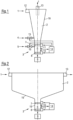
Figur 1 : einen schematischen Querschnitt durch einen Hydrozyklon, -
Figur 2 : durch einen Sedimentationstankt und -
Figur 3 : einen Längsschnitt durch eine Messanordnung mitKamera 11 undLichtquelle 10.
-
Figure 1 : a schematic cross section through a hydrocyclone, -
Figure 2 : through a sedimentation tank and -
Figure 3 : a longitudinal section through a measuring arrangement withcamera 11 andlight source 10.
Die in
Das feststehende Gehäuse des Hydrozyklons umschließt eine längliche Kammer 2 mit kreisförmigem Querschnitt.The fixed housing of the hydrocyclone encloses an
An einem Ende der Kammer 2 befindet sich ein Einlauf 12, über den die zu reinigende Faserstoff-Suspension 1 tangential eingedüst wird. Hierdurch wird die Faserstoff-Suspension 1 auf eine kreisförmige Bahn gebracht, wobei die Suspension 1 gegen die Wand 19 der Kammer 2 gedrückt wird.At one end of the
Durch die dabei wirkenden Zentrifugal- und Fliehkräfte reichern sich die Schwerteile an der Wand 19 der Kammer 2 und die Leichtteile in der Mitte der Kammer 2 an.Due to the centrifugal and centrifugal forces acting, the heavy parts accumulate on the
Auf diese Weise gelangen die Schwerteile an der Wand 19 der Kammer 2 spiralförmig zum gegenüberliegenden Ende der Kammer 2 mit dem Schwerteil-Abscheider 3, über den die Schwerteile aus dem Hydrozyklon zur Rejektabführung 9 geleitet werden.In this way, the heavy parts on the
Die in der Mitte der Kammer 2 vorhandene, von den Schwerteilen gereinigte Faserstoff-Suspension 1 wird als Leichtteil-Komponente über den Leichtteil-Auslauf 13 abgepumpt.The
Hierzu reicht ein rohrförmiger Leichtteil-Auslauf 13 am einlaufseitigen Ende entlang der Zentrumsachse in die Mitte der Kammer 2.For this purpose, a tubular
An den Einlauf 12 schließt sich in Richtung Schwerteil-Abscheider 3 ein kegelförmiger Hydrozyklon-Abschnitt an, in dem sich der Durchmesser der Kammer 2 zum Abscheider 3 hin kontinuierlich vermindert.A conical hydrocyclone section adjoins the
Durch diese Verjüngung steigt die Rotationsgeschwindigkeit der Suspension 1 derart an, dass sich die Schwerteile an der Wand 19 der Kammer 2 aufkonzentrieren.This taper causes the rotation speed of the
Im Unterschied hierzu zeigt
Die Suspension 1 gelangt über einen Einlauf 12 in die Kammer 2 des Sedimentationstanks. Wegen des höheren Gewichts sinken die Schwerteile auf den Boden der Kammer 2 und sammeln sich dort in einer Senke des Bodens, welche zum Schwerteil-Abscheider 3 führt. Auch hier werden die Schwerteile vom Schwerteil-Abscheider 3 zur Rejektabführung 9 geleitet.The
Das so gereinigte Fluid kann dann über den Leichteil-Auslauf 13 abgeführt werden.The fluid cleaned in this way can then be discharged via the
In beiden Fällen besitzt der Schwerteil-Abscheiders 3 einen Rejektraum 6, der von zwei steuerbaren Schiebern 7,8 begrenzt wird. Während ein Schieber 7 zur Kammer 2 der Reinigungsvorrichtung weist, ist der andere Schieber 8 zur Rejektabführung 9 gerichtet.In both cases, the heavy part separator 3 has a
Sollen Schwerteile in dem Rejektraum 6 gesammelt werden, so ist der Schieber 7 zur Kammer 2 offen und der Schieber 8 zur Rejektabführung 9 geschlossen. Hat sich genügend Rejekt im Rejektraum 6 angesammelt so wird dieser geleert, indem der Schieber 7 zur Kammer 2 geschlossen und anschließend der Schieber 8 zur Rejektabführung 9 geöffnet wird.If heavy parts are to be collected in the
Die Ansteuerung dieser Schieber 7,8 zur Leerung des Abscheiders 3 erfolgt von einer Steuervorrichtung 14 in Abhängigkeit vom Umfang der Störfracht und/oder der Schütthöhe in dem Rejektraum 6.These
Beim Hydroyzklon gemäß
Außerdem wird noch Verdünnungsflüssigkeit 4 über ein Ventil 15 in einen unmittelbar vor dem Schwerteil-Abscheider 3 liegenden Abschnitt der Kammer 2 in die Suspension 1 geleitet. Die Eindüsung dieser Verdünnungsflüssigkeit 4 kann tangential oder entgegen der Richtung der Rotationsströmung der Suspension 1 in der Kammer 2 erfolgen, wodurch die Rotationsströmung auch zur Vermeidung eines hohen Verschleißes beeinflusst werden kann.In addition,
Der Umfang der zugeführten Verdünnungsflüssigkeit 4,5 wird von der Steuervorrichtung 14 über eine entsprechende Ansteuerung der Ventile 15,16 geregelt. Dabei nutzt die Steuervorrichtung 14 Informationen zum Grad der Turbulenz und/oder zum Umfang der Störfracht im Rejektraum 6. Hierbei ist auch zu berücksichtigen, dass zu viel Verdünnungsflüssigkeit 4,5 Rejekt in die Kammer 2 zurückspülen kann, was die Abscheideleistung mindert.The amount of dilution liquid 4.5 supplied is regulated by the
Auch beim Sedimentationstank kann eine Verdünnung vor dem Schwerteil-Abscheider 3 oder in den Rejektraum 6 desselben erfolgen und in gleicher Weise wie beim Hydrozyklon gesteuert werden. Im Allgemeinen dient dies dann zur Vermeidung einer Verstopfung.In the sedimentation tank, dilution can also take place in front of the heavy part separator 3 or in the
Unabhängig vom Einsatzfall werden die Parameter des Schwerteil-Abscheiders 3 bezüglich dem Grad der Turbulenz, dem Umfang der Störstofffracht sowie der Schütthöhe optisch erfasst. Hierzu weist die Wandung 19 des Rejektraums 6 ein Schauglas 18 auf, dem eine Lichtquelle 10 und eine Kamera 11 außerhalb des Rejektraums 6 zugeordnet ist.Regardless of the application, the parameters of the heavy part separator 3 are optically recorded with regard to the degree of turbulence, the extent of the contaminant load and the dumping height. For this purpose, the
Zur Auflicht-Beobachtung verläuft die Lichtquelle 10 in Form mehrere LEDs ringförmig um die Kamera 11. Dies sorgt für eine gleichmäßige Ausleuchtung.For incident light observation, the
Um dabei eine Beeinträchtigung des Sichtbereichs der Kamera 11 durch die Lichtquelle 10 zu vermeiden, befindet sich zwischen Lichtquelle 10 und Kamera 11 gemäß
Von dieser Kamera 11 werden die Messdaten an die Steuervorrichtung 14 übermittelt und dort ausgewertet. Dabei wird der Grad der Turbulenz über eine Auswertung der Geschwindigkeit der Partikel im Rejektraum 6, der Umfang der Störstofffracht über eine Auswertung der Dichte der Partikel im Rejektraum 6 und die Schütthöhe im Rejektraum des Schwerteilabscheiders 3 über eine Auswertung des Verhältnisses zwischen der Anzahl an ruhenden und an sich bewegenden Partikeln erfasst.The measurement data is transmitted from this
Claims (14)
- Control method of a device for cleaning a suspension (1), said device having at least one chamber (2) for the suspension (1) and a heavy fraction separator (3) that is connected thereto,
characterized inthat the degree of turbulence and/or the extent of the contaminant load and/or the bulk height is optically detected in the area of the heavy fraction separator (3) and is taken this into account during the control of the device, whereinthe change in position of individual particles is evaluated during the optical detection. - Control method according to Claim 1,
characterized in
that the degree of turbulence is detected by evaluating the velocity of individual particles in the suspension (1). - Control method according to one of the preceding claims,
characterized in
that the extent of the contaminant load is detected by evaluating the concentration of the particles in the suspension (1). - Control method according to one of the preceding claims,
characterized in
that the bulk height in the heavy fraction separator (3) is detected by evaluating the ratio between the number of stationary and moving particles. - Control method according to one of the preceding claims,
characterized in
that dilution fluid (4,5) is fed into the suspension (1) in the area of the heavy fraction separator (3) and/or a section of the chamber (2) that lies upstream thereof and the amount of dilution fluid is controlled in dependence upon the degree of turbulence and/or the extent of the contaminant load. - Control method according to one of the preceding claims,
characterized in
that the heavy fraction separator (3) comprises a reject chamber (6) which is delimited by two controllable slide valves (7,8), of which one faces the chamber (2) and the other faces a reject discharge (9), wherein during the normal operation the slide valve (7) to chamber (2) is open and the slide valve (8) to reject discharge (9) is closed and so as to empty the reject chamber (6) the slide valve (7) to chamber (2) is closed and subsequently the slide valve (8) to the reject discharge (9) is opened. - Control method according to Claim 6,
characterized in
that the control of the slide valves (7, 8) is controlled in dependence upon the extent of the contaminant load and/or the bulk height in the reject chamber (6). - Control method according to Claim 6 or 7,
characterized in
that for the optical detection, at least one light source (10) and one camera (11) are arranged on at least one side of the reject chamber (6). - Control method according to Claim 8,
characterized in
that that the wall (19) of the reject chamber (6) is light-permeable in sections and the light source (10) and/or the camera (11) are arranged outside the reject chamber (6). - Control method according to Claim 9,
characterized in
that the light source (10) and the camera (11) are arranged outside the reject chamber (6) opposite the light-permeable section of the wall (19) of the reject chamber (6), and a partition (17) that extends as far as the wall (19) of the reject chamber (6) is provided between the light source (10) and the camera (11). - Control method according to one of the preceding claims,
characterized in that
the device is designed as a hydrocyclone. - Control method according to Claim 11,
characterized in that
the hydrocyclone comprises a chamber (2) having a circular cross-section into which an inlet (12) and a light fraction outlet (13) issue at one end and a heavy fraction separator (3) issues at the opposite end. - Control method according to one of Claims 1 to 10,
characterized in that
the device is designed as a sedimentation tank having an inlet (12) and a heavy fraction separator (3). - Control method according to one of the preceding claims,
characterized in that
the fibrous suspension (1) that is used for the production of a paper, board, tissue or another fibrous web preferably has a stock concentration of between 0.5 and 6%, in particular between 1.5 and 3.5%, at the inlet (12) .
Applications Claiming Priority (2)
| Application Number | Priority Date | Filing Date | Title |
|---|---|---|---|
| DE102018122808.2A DE102018122808A1 (en) | 2018-09-18 | 2018-09-18 | Control method of a cleaning device with heavy part separator |
| PCT/EP2019/071214 WO2020057851A1 (en) | 2018-09-18 | 2019-08-07 | Control method for a cleaning device with a heavy-fraction separator |
Publications (3)
| Publication Number | Publication Date |
|---|---|
| EP3852933A1 EP3852933A1 (en) | 2021-07-28 |
| EP3852933B1 true EP3852933B1 (en) | 2023-10-11 |
| EP3852933C0 EP3852933C0 (en) | 2023-10-11 |
Family
ID=67551554
Family Applications (1)
| Application Number | Title | Priority Date | Filing Date |
|---|---|---|---|
| EP19752177.6A Active EP3852933B1 (en) | 2018-09-18 | 2019-08-07 | Control method for a cleaning device with a heavy-fraction separator |
Country Status (6)
| Country | Link |
|---|---|
| EP (1) | EP3852933B1 (en) |
| CN (1) | CN112714675B (en) |
| DE (1) | DE102018122808A1 (en) |
| ES (1) | ES2964543T3 (en) |
| PL (1) | PL3852933T3 (en) |
| WO (1) | WO2020057851A1 (en) |
Family Cites Families (20)
| Publication number | Priority date | Publication date | Assignee | Title |
|---|---|---|---|---|
| DE3211865C2 (en) * | 1982-03-31 | 1987-03-26 | Gewerkschaft Auguste Victoria, 4370 Marl | Slurry dewatering device |
| GB8327218D0 (en) * | 1983-10-12 | 1983-11-16 | Beloit Corp | Reject handling in cyclones &c |
| DE3904960A1 (en) * | 1989-02-18 | 1990-08-23 | Finckh Maschf | DEVICE FOR SORTING AND DEBELING FIBER SUSPENSIONS |
| CH677327A5 (en) * | 1989-07-28 | 1991-05-15 | Buehler Ag | |
| NL1014410C1 (en) * | 1999-06-21 | 2000-12-22 | Hovex Bv | Separating device, separating unit for such a separating device, and separating method. |
| ATE267909T1 (en) | 1999-07-06 | 2004-06-15 | Voith Paper Patent Gmbh | METHOD AND DEVICE FOR EMPTYING CONTRARY MATERIALS FROM A HYDROCYCLONE |
| JP4180563B2 (en) * | 2004-12-22 | 2008-11-12 | 株式会社 小川環境研究所 | Precipitation separation operation measurement management method and apparatus |
| DE202005003105U1 (en) * | 2005-02-25 | 2005-05-12 | Voith Paper Patent Gmbh | Collection container for heavy particles, separated from a fiber suspension of recycled paper by a hydrocyclone, has an inner cylindrical guide to give an axial flow into the container |
| SE529771C2 (en) * | 2005-04-29 | 2007-11-20 | Gl & V Man Hungary Kft Hermina | Hydrocyclone unit and method for separating a fiber pulp suspension containing relatively heavy impurities |
| FI122973B (en) * | 2005-06-17 | 2012-09-28 | Metso Paper Inc | Injector for flotation cell, nozzle part in injector for flotation cell, flotation cell and method for mixing fiber suspension strip and air with each other in injector for flotation cell |
| CN100415338C (en) * | 2007-06-01 | 2008-09-03 | 华电水处理技术工程有限公司 | Method and equipment for purifying recirculated cooling water or town B-grade sewage |
| JP4968743B2 (en) * | 2008-02-15 | 2012-07-04 | 三菱重工環境・化学エンジニアリング株式会社 | Liquid classification device and blockage detection method |
| AT506940B1 (en) * | 2008-12-12 | 2010-01-15 | Abz Zierler Ges M B H & Co Kg | DEVICE FOR SEPARATING SOLID PARTICLES FROM A DUMP |
| JP2010142894A (en) * | 2008-12-18 | 2010-07-01 | Teral Inc | Liquid cyclone apparatus |
| SE535959C2 (en) * | 2010-01-29 | 2013-03-05 | Alfa Laval Corp Ab | Systems including centrifugal separator and method of checking the same |
| DE102010027680B4 (en) * | 2010-06-16 | 2012-03-22 | Akw Apparate + Verfahren Gmbh | Method for scanning the underflow jet of a hydrocyclone |
| CN203755075U (en) * | 2013-10-25 | 2014-08-06 | 福伊特造纸(中国)有限公司 | Spiral-flow type paper-pulp slag remover for making paper |
| CN104549794A (en) * | 2014-12-23 | 2015-04-29 | 中国石油天然气股份有限公司 | Underflow control device of hydrocyclone |
| CN106238234B (en) * | 2016-10-14 | 2018-08-21 | 大连碧蓝节能环保科技有限公司 | Adjustable hydrocyclone separator in parallel |
| DE102016122225B4 (en) * | 2016-11-18 | 2018-11-08 | Voith Patent Gmbh | Hydrocyclone arrangement |
-
2018
- 2018-09-18 DE DE102018122808.2A patent/DE102018122808A1/en not_active Ceased
-
2019
- 2019-08-07 WO PCT/EP2019/071214 patent/WO2020057851A1/en unknown
- 2019-08-07 EP EP19752177.6A patent/EP3852933B1/en active Active
- 2019-08-07 PL PL19752177.6T patent/PL3852933T3/en unknown
- 2019-08-07 CN CN201980060808.XA patent/CN112714675B/en active Active
- 2019-08-07 ES ES19752177T patent/ES2964543T3/en active Active
Also Published As
| Publication number | Publication date |
|---|---|
| EP3852933A1 (en) | 2021-07-28 |
| ES2964543T3 (en) | 2024-04-08 |
| WO2020057851A1 (en) | 2020-03-26 |
| CN112714675B (en) | 2023-04-07 |
| DE102018122808A1 (en) | 2020-03-19 |
| CN112714675A (en) | 2021-04-27 |
| EP3852933C0 (en) | 2023-10-11 |
| PL3852933T3 (en) | 2024-02-19 |
Similar Documents
| Publication | Publication Date | Title |
|---|---|---|
| AT511837B1 (en) | HYDROCYCLONE WITH FINANCIAL SUPPLEMENT IN THE CYCLONE SUBSTITUTE | |
| EP2049222B1 (en) | Filter apparatus | |
| DE3030980A1 (en) | HYDROCYCLONE. | |
| EP1215335B1 (en) | Pressure screen for cleaning paper pulp containing impurities | |
| DE102004051327B4 (en) | Method for degassing and feeding a pulp suspension to a headbox and degassing | |
| EP2516733A1 (en) | Method and screening device for screening a fiber suspension | |
| EP1598477B1 (en) | Pressure screen for screening a fibrous suspension | |
| DE69217081T2 (en) | HYDROCYCLONE WITH TURBULENCE GENERATING AGENTS | |
| EP3852933B1 (en) | Control method for a cleaning device with a heavy-fraction separator | |
| DE69611732T3 (en) | screening device | |
| AT408770B (en) | SORTER FOR CLEANING A FIBER SUSPENSION | |
| EP1860231A2 (en) | Method and device for cleaning paper raw materials containing impurities | |
| DE102005016192A1 (en) | Process for dissolving and cleaning contaminant-containing paper tubes | |
| EP1876289B1 (en) | Method for separating impurities from a fibrous suspension | |
| EP1830001A2 (en) | Device for discharging heavy parts from an apparatus for treating a pulp suspension, in particular from a hydrocyclone which can be operated to clean a pulp suspension | |
| AT506940B1 (en) | DEVICE FOR SEPARATING SOLID PARTICLES FROM A DUMP | |
| EP1262594B1 (en) | Process for separating specified materials from an aqueous fibrous material suspension | |
| DE1442501B2 (en) | Hydrocyclone | |
| DE102004039712B4 (en) | Reject flow control, from a used paper suspension sorting station, has a flow measurement point in front of a throttle linked to a control to set the delivery of a diluting fluid to prevent throttle blockages | |
| AT16830U1 (en) | Discharge device | |
| DE102004051887B3 (en) | Pressure material sorting system for sieving suspension of fibers in liquid has vessel with tangential entry and narrow gap leading to chamber inside cylindrical sieve containing rotor with paddles | |
| DE19748233A1 (en) | Water filter for coarse particulate matter arising from industrial process introduces tangential flow of water into filter | |
| DE1442501C (en) | Hydrocyclone | |
| DE102021112389A1 (en) | Multi-stage sorting device | |
| DE1924417U (en) | DEVICE FOR EXTRACTION OF FOREIGN BODIES FROM A FLOWABLE MEDIUM WITH A CYLINDRICAL AND / OR FOR DISCHARGE OPENING FOR THE FOREIGN BODIES TAPPING SEPARATION AREA. |
Legal Events
| Date | Code | Title | Description |
|---|---|---|---|
| STAA | Information on the status of an ep patent application or granted ep patent |
Free format text: STATUS: UNKNOWN |
|
| STAA | Information on the status of an ep patent application or granted ep patent |
Free format text: STATUS: THE INTERNATIONAL PUBLICATION HAS BEEN MADE |
|
| STAA | Information on the status of an ep patent application or granted ep patent |
Free format text: STATUS: THE INTERNATIONAL PUBLICATION HAS BEEN MADE |
|
| PUAI | Public reference made under article 153(3) epc to a published international application that has entered the european phase |
Free format text: ORIGINAL CODE: 0009012 |
|
| STAA | Information on the status of an ep patent application or granted ep patent |
Free format text: STATUS: REQUEST FOR EXAMINATION WAS MADE |
|
| 17P | Request for examination filed |
Effective date: 20210419 |
|
| AK | Designated contracting states |
Kind code of ref document: A1 Designated state(s): AL AT BE BG CH CY CZ DE DK EE ES FI FR GB GR HR HU IE IS IT LI LT LU LV MC MK MT NL NO PL PT RO RS SE SI SK SM TR |
|
| DAV | Request for validation of the european patent (deleted) | ||
| DAX | Request for extension of the european patent (deleted) | ||
| GRAP | Despatch of communication of intention to grant a patent |
Free format text: ORIGINAL CODE: EPIDOSNIGR1 |
|
| STAA | Information on the status of an ep patent application or granted ep patent |
Free format text: STATUS: GRANT OF PATENT IS INTENDED |
|
| INTG | Intention to grant announced |
Effective date: 20230509 |
|
| GRAS | Grant fee paid |
Free format text: ORIGINAL CODE: EPIDOSNIGR3 |
|
| GRAA | (expected) grant |
Free format text: ORIGINAL CODE: 0009210 |
|
| STAA | Information on the status of an ep patent application or granted ep patent |
Free format text: STATUS: THE PATENT HAS BEEN GRANTED |
|
| AK | Designated contracting states |
Kind code of ref document: B1 Designated state(s): AL AT BE BG CH CY CZ DE DK EE ES FI FR GB GR HR HU IE IS IT LI LT LU LV MC MK MT NL NO PL PT RO RS SE SI SK SM TR |
|
| REG | Reference to a national code |
Ref country code: GB Ref legal event code: FG4D Free format text: NOT ENGLISH |
|
| REG | Reference to a national code |
Ref country code: CH Ref legal event code: EP |
|
| REG | Reference to a national code |
Ref country code: DE Ref legal event code: R096 Ref document number: 502019009652 Country of ref document: DE |
|
| REG | Reference to a national code |
Ref country code: IE Ref legal event code: FG4D Free format text: LANGUAGE OF EP DOCUMENT: GERMAN |
|
| U01 | Request for unitary effect filed |
Effective date: 20231011 |
|
| U07 | Unitary effect registered |
Designated state(s): AT BE BG DE DK EE FI FR IT LT LU LV MT NL PT SE SI Effective date: 20231017 |
|
| PG25 | Lapsed in a contracting state [announced via postgrant information from national office to epo] |
Ref country code: GR Free format text: LAPSE BECAUSE OF FAILURE TO SUBMIT A TRANSLATION OF THE DESCRIPTION OR TO PAY THE FEE WITHIN THE PRESCRIBED TIME-LIMIT Effective date: 20240112 |
|
| REG | Reference to a national code |
Ref country code: ES Ref legal event code: FG2A Ref document number: 2964543 Country of ref document: ES Kind code of ref document: T3 Effective date: 20240408 |
|
| PG25 | Lapsed in a contracting state [announced via postgrant information from national office to epo] |
Ref country code: IS Free format text: LAPSE BECAUSE OF FAILURE TO SUBMIT A TRANSLATION OF THE DESCRIPTION OR TO PAY THE FEE WITHIN THE PRESCRIBED TIME-LIMIT Effective date: 20240211 |
|
| PG25 | Lapsed in a contracting state [announced via postgrant information from national office to epo] |
Ref country code: IS Free format text: LAPSE BECAUSE OF FAILURE TO SUBMIT A TRANSLATION OF THE DESCRIPTION OR TO PAY THE FEE WITHIN THE PRESCRIBED TIME-LIMIT Effective date: 20240211 Ref country code: GR Free format text: LAPSE BECAUSE OF FAILURE TO SUBMIT A TRANSLATION OF THE DESCRIPTION OR TO PAY THE FEE WITHIN THE PRESCRIBED TIME-LIMIT Effective date: 20240112 |
|
| PG25 | Lapsed in a contracting state [announced via postgrant information from national office to epo] |
Ref country code: RS Free format text: LAPSE BECAUSE OF FAILURE TO SUBMIT A TRANSLATION OF THE DESCRIPTION OR TO PAY THE FEE WITHIN THE PRESCRIBED TIME-LIMIT Effective date: 20231011 Ref country code: NO Free format text: LAPSE BECAUSE OF FAILURE TO SUBMIT A TRANSLATION OF THE DESCRIPTION OR TO PAY THE FEE WITHIN THE PRESCRIBED TIME-LIMIT Effective date: 20240111 Ref country code: HR Free format text: LAPSE BECAUSE OF FAILURE TO SUBMIT A TRANSLATION OF THE DESCRIPTION OR TO PAY THE FEE WITHIN THE PRESCRIBED TIME-LIMIT Effective date: 20231011 |
|
| REG | Reference to a national code |
Ref country code: DE Ref legal event code: R097 Ref document number: 502019009652 Country of ref document: DE |
|
| PG25 | Lapsed in a contracting state [announced via postgrant information from national office to epo] |
Ref country code: CZ Free format text: LAPSE BECAUSE OF FAILURE TO SUBMIT A TRANSLATION OF THE DESCRIPTION OR TO PAY THE FEE WITHIN THE PRESCRIBED TIME-LIMIT Effective date: 20231011 |
|
| PG25 | Lapsed in a contracting state [announced via postgrant information from national office to epo] |
Ref country code: SK Free format text: LAPSE BECAUSE OF FAILURE TO SUBMIT A TRANSLATION OF THE DESCRIPTION OR TO PAY THE FEE WITHIN THE PRESCRIBED TIME-LIMIT Effective date: 20231011 |
|
| PG25 | Lapsed in a contracting state [announced via postgrant information from national office to epo] |
Ref country code: SM Free format text: LAPSE BECAUSE OF FAILURE TO SUBMIT A TRANSLATION OF THE DESCRIPTION OR TO PAY THE FEE WITHIN THE PRESCRIBED TIME-LIMIT Effective date: 20231011 Ref country code: SK Free format text: LAPSE BECAUSE OF FAILURE TO SUBMIT A TRANSLATION OF THE DESCRIPTION OR TO PAY THE FEE WITHIN THE PRESCRIBED TIME-LIMIT Effective date: 20231011 Ref country code: RO Free format text: LAPSE BECAUSE OF FAILURE TO SUBMIT A TRANSLATION OF THE DESCRIPTION OR TO PAY THE FEE WITHIN THE PRESCRIBED TIME-LIMIT Effective date: 20231011 Ref country code: CZ Free format text: LAPSE BECAUSE OF FAILURE TO SUBMIT A TRANSLATION OF THE DESCRIPTION OR TO PAY THE FEE WITHIN THE PRESCRIBED TIME-LIMIT Effective date: 20231011 |
|
| PLBE | No opposition filed within time limit |
Free format text: ORIGINAL CODE: 0009261 |
|
| STAA | Information on the status of an ep patent application or granted ep patent |
Free format text: STATUS: NO OPPOSITION FILED WITHIN TIME LIMIT |
|
| 26N | No opposition filed |
Effective date: 20240712 |