EP1598477B1 - Pressure screen for screening a fibrous suspension - Google Patents
Pressure screen for screening a fibrous suspension Download PDFInfo
- Publication number
- EP1598477B1 EP1598477B1 EP05006347A EP05006347A EP1598477B1 EP 1598477 B1 EP1598477 B1 EP 1598477B1 EP 05006347 A EP05006347 A EP 05006347A EP 05006347 A EP05006347 A EP 05006347A EP 1598477 B1 EP1598477 B1 EP 1598477B1
- Authority
- EP
- European Patent Office
- Prior art keywords
- pressure
- screen
- pressure grader
- suspension
- outlet
- Prior art date
- Legal status (The legal status is an assumption and is not a legal conclusion. Google has not performed a legal analysis and makes no representation as to the accuracy of the status listed.)
- Expired - Lifetime
Links
Images
Classifications
-
- D—TEXTILES; PAPER
- D21—PAPER-MAKING; PRODUCTION OF CELLULOSE
- D21D—TREATMENT OF THE MATERIALS BEFORE PASSING TO THE PAPER-MAKING MACHINE
- D21D5/00—Purification of the pulp suspension by mechanical means; Apparatus therefor
- D21D5/02—Straining or screening the pulp
- D21D5/023—Stationary screen-drums
- D21D5/026—Stationary screen-drums with rotating cleaning foils
-
- D—TEXTILES; PAPER
- D21—PAPER-MAKING; PRODUCTION OF CELLULOSE
- D21D—TREATMENT OF THE MATERIALS BEFORE PASSING TO THE PAPER-MAKING MACHINE
- D21D1/00—Methods of beating or refining; Beaters of the Hollander type
- D21D1/20—Methods of refining
- D21D1/34—Other mills or refiners
-
- D—TEXTILES; PAPER
- D21—PAPER-MAKING; PRODUCTION OF CELLULOSE
- D21D—TREATMENT OF THE MATERIALS BEFORE PASSING TO THE PAPER-MAKING MACHINE
- D21D5/00—Purification of the pulp suspension by mechanical means; Apparatus therefor
- D21D5/02—Straining or screening the pulp
- D21D5/16—Cylinders and plates for screens
-
- D—TEXTILES; PAPER
- D21—PAPER-MAKING; PRODUCTION OF CELLULOSE
- D21D—TREATMENT OF THE MATERIALS BEFORE PASSING TO THE PAPER-MAKING MACHINE
- D21D5/00—Purification of the pulp suspension by mechanical means; Apparatus therefor
- D21D5/18—Purification of the pulp suspension by mechanical means; Apparatus therefor with the aid of centrifugal force
- D21D5/22—Purification of the pulp suspension by mechanical means; Apparatus therefor with the aid of centrifugal force in apparatus with a vertical axis
Definitions
- the invention relates to a pressure sorter according to the preamble of claim 1 and to a use of a pressure sorter according to claims 13 and 15.
- Pressure sorters are used in the processing of paper fiber suspensions, in order to process the pulp suspension in a wet sieving.
- a pressure sorter contains at least one screen, which is provided with a plurality of openings.
- the fibers contained in the suspension are to pass through the openings, while rejecting the unwanted solid constituents thereto and are led out of the sorter again.
- sorting holes round holes or slots are usually used.
- pressure sorters of the type considered here are equipped with screen scrapers that are moved close to the screen. As a result, clogging of the screen openings is prevented in a manner known per se.
- the separation effect of a pressure sorter is therefore attributable to the fact that at least some of the impurities contained in the paper pulp suspension fed can not pass through the sieve, that is to say it is separated from the paper fibers due to its size, shape or flexibility.
- pressure sorters are known in which additionally targeted to the density of the impurities separation is made by the different forces of the impurities are used in a centrifugal field.
- the separation effect can only be optimally achieved in hydrocyclones and centrifuges, it can still be useful in pressure sorters. Although a large part of the heavy parts would not pass through the screen openings usually used, so be rejected there, but there is a risk of damage or wear when they come into contact with the sieve. This risk is aggravated by the fact that almost always used are Sieblusterr that move very close to the screen at a relatively high speed.
- pressure graders which in highly contaminated paper fiber suspensions be used by upstream hydrocyclones, so-called thicker scavenger, to protect against coarse heavy particles. This is effective, but with additional effort.
- Another way to reduce wear on the screen of the sorter is to place the sifter on the accept side of the screen.
- the rejected parts on the screen have a lower speed and can not be detected by the sieve scraper.
- the damage caused by pinching of metal parts between the sieve and Siebêtrn is very unlikely.
- the invention is based on the object of further improving the known pressure sorters, so that even a considerable part of the contaminants can be removed from the paper fiber suspension before they strike the screen. In particular wear-promoting heavy parts and sensitive lightweight parts should be removed early.
- the inlet chamber This is generally annular and is supplied by a tangentially attached inlet with the pulp suspension to be sorted, whereby a rotational flow is formed.
- the heavy parts are thrown radially outward, so that they can not or hardly come into contact with the sieve. They drive in the direction of the inner wall of the housing and are partly further dragged by the suspension flow and partly transported by gravity into a part of the Zulaufraumes, from which they can be easily removed.
- FIG. 1 A typical embodiment of the pressure sorter according to the invention is shown in FIG. 1.
- This contains in a housing 2 a sieve 1 in the form of a cylindrical screen basket.
- the center line of the screen 1 is perpendicular here in the position of use of the device.
- the sieve openings are advantageously cylindrical along their entire length with a diameter between one and three millimeters.
- the pulp suspension S to be screened is introduced into the housing 2 through an inlet 8. In the process, it first passes into the inlet space 4, which extends substantially annularly and radially outside the screen 1 as part of the housing 2.
- the inlet 8 is connected tangentially to the inlet chamber 4, so that a rotational flow forms during operation of the machine in the inlet chamber 4, which runs in the clockwise direction in this illustration.
- the supplied pulp suspension S moves in the inlet space 4 helically downwards, with a considerable part of this suspension pass through the sieve opening of the sieve 1 and can reach into the accepts space 3 located radially inside the sieve 1.
- a conically tapering portion 15 of the inlet chamber 4 the peripheral velocity of the suspension is maintained or increased, even if their amount decreases due to the outflow through the wire 1.
- the fibrous suspension S to be screened is contaminated not only with heavy but also with light parts, which include, in particular, polystyrene or other light foams. These are quickly separated from the heavy parts due to the centrifugal forces and can be removed early because they move due to their tendency to rise in the liquid-filled feed space 4 in the upper part. There they are discharged through thechtteilauslass 11. This can, as here, lead vertically upwards or obliquely upwards, or also tangentially connected.
- an impermeable cylinder wall 14 lying above the screen 1 for the purpose of separating the inlet space 4 and the accepts space 3, so that a lightweight part collecting space is formed in the upper part of the inlet space 4.
- This can cause a significant calming of the flow, whereby the lightweight parts and possibly air can be separated even better.
- the axial length of this cylinder wall 14 is only a fraction of the axial length of the screen 1, for example, about 20%.
- the climbing effect of the lightweight parts can be additionally supported in this area by a fixed helix, which deflects the circumferential movement into a rising motion.
- reject R The largest part of the suspension rejected at the sieve 1, in particular the contaminants entrained by flow forces, are removed from the housing 2 at the reject outlet 10 as reject R. It is usually sorted to avoid fiber loss.
- the accepts space 3 has here at its uppermost part a vent line 12 through which air and possibly also very fine lightweight parts can be removed from the accepts.
- Figures 3 and 4 serve to show even more solutions with specific details.
- the device according to FIG. 3 has a modified flow guidance in that the accept A from the accept chamber 3 is not discharged downwards, as in FIG. 1, but upwards, ie, that the Gutstoffauslass 9 'is centrally connected to the upper wall of Acceptance space 3.
- the deducted accepts A then contains in addition to the sorted fibers and air, which is why a further vent line can be omitted.
- the ejected in the inlet space 4 to the outside heavy parts are guided by a vertical or oblique on the housing 2 radially projecting Schwerteilkanal 18 directly down to the heavy section lock 13.
- the pressure sorter in Fig. 4 is provided with an inlet space 4 ', whose cross section over the axial height is kept substantially constant, since it was dispensed with a tapered portion. Also, a special separate light parts collection space above the screen 1 can be omitted if necessary, to save height.
- the lightweight parts are immediately dissipated by thechtteilauslass 11.
- In the lower part of the inlet chamber 4 ' is a downwardly sloping end wall 19, which leads out there arrived heavy parts together with the reject R through the reject outlet 10 from the housing. Conveniently, the reject outlet 10 is connected at the lowest point. Another Schwerteilauslass can then be saved.
- the end wall 19 may have an arcuate shape.
- this device is the pre or coarse sorting of dissolved pulp.
- This may typically be a recovered paper pulp suspension formed in a pulper 21 from recovered paper P and water W and withdrawn through a coarse pulp screen 22, as shown in FIG.
- a Pulpersieb 22 is kept free by a rotor 23 and usually has holes with a diameter between 10 and 25 mm.
- the withdrawn by this waste paper suspension is pumped without further screening device via fuel pump 24 into the inlet 8 of an inventively designed pressure sorter. Therefore, this suspension S may be mixed with a larger amount of impurities, which can easily be retained on screen openings whose diameter, for example, in a range between 1 and 3 mm lies.
- such soiled waste paper suspensions may be prepared in a high consistency pulper or in a downstream open wire disintegrating drum, such as an open sorting drum, and diluted.
- a dissolving drum that is suitable for the process shows the German patent application DE 197 36 143 ,
Landscapes
- Engineering & Computer Science (AREA)
- Mechanical Engineering (AREA)
- Paper (AREA)
- Separation Of Solids By Using Liquids Or Pneumatic Power (AREA)
- Combined Means For Separation Of Solids (AREA)
Abstract
Description
Die Erfindung betrifft einen Drucksortierer gemäß dem Oberbegriff des Anspruchs 1 sowie eine Verwendung eines Drucksortierers gemäß den Ansprüchen 13 und 15.The invention relates to a pressure sorter according to the preamble of
Drucksortierer werden bei der Aufbereitung von Papierfasersuspensionen eingesetzt, und zwar um die Faserstoffsuspension in einer Nasssiebung zu bearbeiten. Dazu enthält ein solcher Drucksortierer mindestens ein Sieb, das mit einer Vielzahl von Öffnungen versehen ist. Die in der Suspension enthaltenen Fasern sollen durch die Öffnungen hindurch treten, während die nicht gewünschten festen Bestandteile daran abgewiesen und aus dem Sortierer wieder herausgeleitet werden. Als Sortieröffnungen werden in der Regel runde Löcher oder Schlitze verwendet. In den meisten Fällen sind Drucksortierer der hier betrachteten Art mit Siebräumern ausgestattet, die dicht an dem Sieb vorbeibewegt werden. Dadurch wird in an sich bekannter Weise das Zusetzen der Sieböffnungen verhindert.Pressure sorters are used in the processing of paper fiber suspensions, in order to process the pulp suspension in a wet sieving. For this purpose, such a pressure sorter contains at least one screen, which is provided with a plurality of openings. The fibers contained in the suspension are to pass through the openings, while rejecting the unwanted solid constituents thereto and are led out of the sorter again. As sorting holes round holes or slots are usually used. In most cases, pressure sorters of the type considered here are equipped with screen scrapers that are moved close to the screen. As a result, clogging of the screen openings is prevented in a manner known per se.
Die Trennwirkung eines Drucksortierers ist also darauf zurückzuführen, dass zumindest ein Teil der in der zugeführten Papierfasersuspension enthaltenen Verunreinigungen nicht das Sieb passieren kann, also auf Grund der Größe, Form oder Flexibilität von den Papierfasern getrennt wird. Es sind auch Drucksortierer bekannt, bei denen zusätzlich eine speziell auf die Dichte der Störstoffe zielende Trennung vorgenommen wird, indem die in einem Zentrifugalfeld unterschiedlichen Kräfte der Störstoffe genutzt werden. Auch wenn sich die Trennwirkung optimal nur in Hydrozyklonen und Zentrifugen erreichen lässt, kann sie dennoch auch in Drucksortierern nützlich sein. Zwar würde ein großer Teil der Schwerteile ohnehin nicht durch die üblicherweise verwendeten Sieböffnungen hindurch passen, also dort abgewiesen werden, es besteht jedoch die Gefahr der Beschädigung oder des Verschleißes, wenn sie mit dem Sieb in Kontakt kommen. Verstärkt wird dieses Risiko noch dadurch, dass fast immer Siebräumer verwendet werden, die sich sehr dicht am Sieb mit relativ hoher Geschwindigkeit vorbeibewegen.The separation effect of a pressure sorter is therefore attributable to the fact that at least some of the impurities contained in the paper pulp suspension fed can not pass through the sieve, that is to say it is separated from the paper fibers due to its size, shape or flexibility. There are also pressure sorters are known in which additionally targeted to the density of the impurities separation is made by the different forces of the impurities are used in a centrifugal field. Although the separation effect can only be optimally achieved in hydrocyclones and centrifuges, it can still be useful in pressure sorters. Although a large part of the heavy parts would not pass through the screen openings usually used, so be rejected there, but there is a risk of damage or wear when they come into contact with the sieve. This risk is aggravated by the fact that almost always used are Siebräumer that move very close to the screen at a relatively high speed.
Es ist ohne weiteres möglich, Drucksortierer, die bei stark störstoffhaltigen Papierfasersuspensionen eingesetzt werden, durch vorgeschaltete Hydrozyklone, sogenannte Dickstoffreiniger, vor groben Schwerteilen zu schützen. Das ist zwar wirksam, aber mit zusätzlichem Aufwand verbunden.It is easily possible, pressure graders, which in highly contaminated paper fiber suspensions be used by upstream hydrocyclones, so-called thicker scavenger, to protect against coarse heavy particles. This is effective, but with additional effort.
Eine andere Maßnahme, um den Verschleiß am Sieb des Drucksortierers zu reduzieren, besteht darin, den Siebräumer auf der Gutstoffseite des Siebes anzuordnen. Das führt dazu, dass die am Sieb abgewiesenen Teile eine geringere Geschwindigkeit haben und nicht vom Siebräumer erfasst werden können. Insbesondere die Beschädigung durch Einklemmen von Metallteilen zwischen Sieb und Siebräumern ist sehr unwahrscheinlich.Another way to reduce wear on the screen of the sorter is to place the sifter on the accept side of the screen. As a result, the rejected parts on the screen have a lower speed and can not be detected by the sieve scraper. In particular, the damage caused by pinching of metal parts between the sieve and Siebräumern is very unlikely.
Bei mit zylindrischen Siebkörben ausgestalteten Drucksortierern der hier betrachteten Art wird oft eine zentripetale Fahrweise angewendet, bei der die Suspension radial von außen nach innen die Sieböffnungen passiert. Schwerteile können dann infolge der Zentrifugalkräfte nicht so leicht zum Sieb gelangen.When designed with cylindrical screen baskets pressure sorters of the type considered here is often a centripetal procedure used, in which the suspension passes radially from outside to inside the sieve openings. Heavy parts can not easily reach the sieve due to the centrifugal forces.
Aus der
Trotz dieser Fortschritte ist der Betrieb von Drucksortierern dieser Art sehr problematisch. So kann nicht ausgeschlossen werden, dass besonders bei stark störstoffhaltigen Suspensionen, wie sie z.B. unmittelbar nach der Altpapierauflösung in der Vorsortierung behandelt werden müssen, immer noch Schwerteile, z.B. Metallstücke, Glasscherben und Steine am Sieb entlang schaben und zu erhöhtem Verschleiß führen. Auch Leichtteile, insbesondere Schaumstoffe (Styropor), werden nicht, zumindest nicht optimal und schnell ausgeschieden. Bei diesen besteht die Gefahr, dass sie im Drucksortierer so weit zerkleinert werden, dass sie in den Gutstoff gelangen und in den nachfolgenden Trennstufen nur noch schlecht abgeschieden werden können. Oder sie konzentrieren sich im Drucksortierer auf und blockieren die Zuströmungswege zum Sieb oder die Sieböffnungen selbst.Despite these advances, the operation of pressure sorters of this type is very problematic. Thus, it can not be ruled out that scrapings, eg pieces of metal, broken glass and stones still scrape along the wire and lead to increased wear, especially in the case of suspensions containing a lot of contaminants, such as must be treated immediately after the waste paper is dissolved in the presorting. Even lightweight parts, especially foams (polystyrene) are not, at least not optimal and quickly excreted. With these, there is a risk that they are crushed in the pressure sorter so far that they get into the accept and can be deposited in the subsequent separation stages only poorly. Or they concentrate in the pressure sorter and block the inflow paths to the sieve or sieve openings themselves.
Der Erfindung liegt die Aufgabe zu Grunde, die bekannten Drucksortierer weiter zu verbessern, so dass schon ein beträchtlicher Teil der Störstoffe aus der Papierfasersuspension entfernt werden kann, bevor diese auf das Sieb auftreffen. Dabei sollen insbesondere Verschleiß fördernde Schwerteile und empfindliche Leichtteile frühzeitig entfernt werden.The invention is based on the object of further improving the known pressure sorters, so that even a considerable part of the contaminants can be removed from the paper fiber suspension before they strike the screen. In particular wear-promoting heavy parts and sensitive lightweight parts should be removed early.
Diese Aufgabe wird bei einem Drucksortierer gemäß Anspruch 1 durch das im Kennzeichen des Anspruchs 1 genannte Merkmal gelöst.This object is achieved in a pressure sorter according to
Bei dem Drucksortierer der angegebenen Art können durch die erfindungsgemäßen Maßnahmen deutlich günstigere Strömungsverhältnisse erzeugt werden, was insbesondere für die Zulaufkammer gilt. Diese ist im Allgemeinen ringförmig und wird durch einen tangential angesetzten Zulauf mit der zu sortierenden Faserstoffsuspension versorgt, wodurch sich eine Rotationsströmung ausbildet. Infolge der dadurch erzeugten Zentrifugalkräfte werden die Schwerteile radial nach außen geschleudert, so dass sie nicht oder kaum mit dem Sieb in Berührung kommen können. Sie treiben in Richtung Innenwand des Gehäuses und werden teils durch die Suspensionsströmung weiter geschleppt und teils infolge der Schwerkraft in einen Teil des Zulaufraumes transportiert, aus dem sie leicht entfernt werden können. Der radial innerhalb des Siebes - also gutstoffseitig - rotierende Siebräumer erzeugt im Gutstoffraum Druck- und Saugimpulse zur Freihaltung der Sieböffnungen. Dabei hat der Siebräumer eine Drehrichtung, die entgegengesetzt der Drehrichtung des sich im Zulaufraum befindenden rotierenden Flüssigkeitsringes gerichtet ist. Das ist deshalb von Vorteil, da die Räumerflügel im Zusammenwirken mit dem Sieb eine gegensinnige Rotationsströmung im Zulaufraum erzeugen, also die sich im Zulaufraum befindende Suspension in der Richtung antreiben, die sie vom Einlauf her bereits hat. Die Leichtteile werden durch die Zentrifugalkräfte von den Schwerteilen separiert und bewegen sich am Sieb entlang nach oben und können leicht abgeführt werden. Infolge der ausgeprägten Rotationsströmung auch direkt am Sieb ist die Neigung der Leichtteile gering, sich daran festzusetzen. Auf diese Weise wird ohne zusätzlichen apparativen Aufwand und bei etwa gleichem Energieverbrauch die Abscheidewirkung von Schwerteilen und von Leichtteilen im Zulaufraum wesentlich verbessert.In the pressure sorter of the specified type significantly more favorable flow conditions can be generated by the inventive measures, which is particularly true for the inlet chamber. This is generally annular and is supplied by a tangentially attached inlet with the pulp suspension to be sorted, whereby a rotational flow is formed. As a result of the centrifugal forces generated thereby, the heavy parts are thrown radially outward, so that they can not or hardly come into contact with the sieve. They drive in the direction of the inner wall of the housing and are partly further dragged by the suspension flow and partly transported by gravity into a part of the Zulaufraumes, from which they can be easily removed. The radial inside of the screen - so good material - rotating Siebräumer generated in Acceptance space pressure and suction pulses to keep free the screen openings. In this case, the Siebräumer has a direction of rotation, which is opposite to the direction of rotation of the located in the Zulaufraum rotating liquid ring. This is advantageous because the Räumerflügel produce in cooperation with the screen an opposing rotational flow in the inlet space, so driving the suspension located in Zulaufraum in the direction that it already has from the inlet ago. The lightweight parts are separated by the centrifugal forces of the heavy parts and move up the sieve up and can be easily removed. Due to the pronounced rotational flow also directly on the screen, the tendency of the light parts is low to stick to it. In this way, the separation efficiency of heavy parts and lightweight parts in the inlet space is substantially improved without additional equipment and at about the same energy consumption.
Die Erfindung und ihre Vorteile werden erläutert an Hand von Zeichnungen. Dabei zeigen:
- Fig. 1
- schematisch geschnitten in Seitenansicht dargestellt, einen erfindungsgemäßen Drucksortierer;
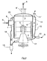
- Fig. 2
- schematisch geschnitten in Aufsicht dargestellt, einen erfindungsgemäßen Drucksortierer;
- Fig. 3+4
- je eine Variation in Seitenansicht;
- Fig. 5
- Schema mit einer vorteilhaften Verwendung des erfindungsgemäßen Drucksortierers.
- Fig. 1
- shown schematically in side view, a pressure sorter according to the invention;
- Fig. 2
- schematically shown in plan view, a pressure sorter according to the invention;
- Fig. 3 + 4
- one variation each in side view;
- Fig. 5
- Scheme with an advantageous use of the pressure sorter according to the invention.
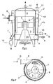
Eine typische Ausführungsform des erfindungsgemäßen Drucksortierers zeigt die Fig. 1. Dieser enthält in einem Gehäuse 2 ein Sieb 1 in Form eines zylindrischen Siebkorbes. Die Mittellinie des Siebes 1 steht hier in Gebrauchslage der Vorrichtung senkrecht. Man spricht daher auch von einem Vertikalsortierer. Die Sieböffnungen sind mit Vorteil auf ihrer ganzen Länge zylindrisch mit einem Durchmesser zwischen einem und drei Millimetern. Die zu siebende Faserstoffsuspension S wird durch einen Zulauf 8 in das Gehäuse 2 eingeführt. Dabei gelangt sie zunächst in den Zulaufraum 4, der sich im Wesentlichen ringförmig und radial außerhalb des Siebes 1 als Teil des Gehäuses 2 erstreckt. Wie aus der Fig. 2 ersichtlich ist, ist der Zulauf 8 tangential an den Zulaufraum 4 angeschlossen, so dass sich bei Betrieb der Maschine im Zulaufraum 4 eine Rotationsströmung ausbildet, die bei dieser Darstellung im Uhrzeigersinn läuft.A typical embodiment of the pressure sorter according to the invention is shown in FIG. 1. This contains in a housing 2 a
Die zugeführte Faserstoffsuspension S bewegt sich im Zulaufraum 4 schraubenlinienförmig nach unten, wobei ein beträchtlicher Teil dieser Suspension die Sieböffnung des Siebes 1 passieren und in den radial innerhalb des Siebes 1 liegenden Gutstoffraum 3 gelangen können. Durch einen konisch sich verjüngenden Abschnitt 15 des Zulaufraumes 4 wird die Umfangsgeschwindigkeit der Suspension erhalten oder gesteigert, auch wenn ihre Menge auf Grund des Abströmens durch das Sieb 1 abnimmt.The supplied pulp suspension S moves in the
Im Gutstoffraum 3 befindet sich der Siebräumer 5, der hier mit einer Anzahl von Flügeln 6 versehen ist, die vorzugsweise mit einer Umfangsgeschwindigkeit von mindestens 15 m/s angetrieben werden. Durch Relativbewegung zu der sie umgebenden Flüssigkeit erzeugen sie Druck- und Saugstöße, mit denen die Sieböffnungen frei gehalten werden. Der Siebräumer 5 ist im unteren Teil des Gehäuses 2 fliegend gelagert (Lager- und Abdichteinheit 16) und wird rotierend angetrieben. Wie Fig. 2 zeigt, wird der Siebräumer 5 so angetrieben, dass seine Umfangsgeschwindigkeit entgegengesetzt der tangentialen Einströmrichtung am Zulauf 8 ist. Die Vorteile dieser Gegenläufigkeit sind bereits genannt worden. Infolge der im Zulaufraum 4 ausgebildeten Rotationsströmung wirken auf die Faserstoffsuspension S Zentrifugalkräfte ein. Diese führen dazu, dass Schwerteile nach außen, also in Richtung Gehäusewand, geschleudert werden. Dadurch werden sie wirksam vom Kontakt mit dem Sieb 1 abgehalten. Sie sammeln sich im unteren Teil des Zulaufraumes 4 und werden z.B. über den Schwerteilauslass 7 in die Schwerteilschleuse 13 abgeleitet, wobei kaum Faserverluste entstehen. In typischen Fällen ist die zu siebende Faserstoffsuspension S nicht nur mit Schwer-, sondern auch mit Leichtteilen verschmutzt, wozu insbesondere Styropor oder sonstige leichte Schaumstoffe gehören. Diese werden infolge der Zentrifugalkräfte schnell von den Schwerteilen separiert und können frühzeitig entfernt werden, da sie sich infolge ihrer Aufsteigetendenz im mit Flüssigkeit gefüllten Zulaufraum 4 in den oberen Teil bewegen. Sie werden dort durch den Leichtteilauslass 11 abgeführt. Dieser kann wie hier senkrecht nach oben oder schräg nach oben führen, oder auch tangential angeschlossen sein. Es kann von Vorteil sein, eine oberhalb des Siebes 1 liegende undurchlässige Zylinderwand 14 zur Abtrennung von Zulaufraum 4 und Gutstoffraum 3 vorzusehen, so dass sich im oberen Teil des Zulaufraumes 4 ein Leichtteilsammelraum bildet. Darin kann eine deutliche Beruhigung der Strömung eintreten, wodurch sich die Leichtteile und eventuell Luft noch besser abscheiden lassen. Die axiale Länge dieser Zylinderwand 14 ist dabei nur ein Bruchteil der axialen Länge des Siebes 1, z.B. ca. 20 %. Die Steigwirkung der Leichtteile kann in diesem Bereich zusätzlich durch eine feststehende Schraubwendel unterstützt werden, die die Umfangsbewegung in eine Steigbewegung umlenkt.In
Der größte Teil der am Sieb 1 abgewiesenen Suspension, insbesondere die durch Strömungskräfte mitgeschleppten Störstoffe, werden am Rejektauslass 10 als Rejekt R aus dem Gehäuse 2 entfernt. Er wird in der Regel nachsortiert, um Faserverluste zu vermeiden.The largest part of the suspension rejected at the
Der Gutstoffraum 3 weist hier an seinem obersten Teil eine Entlüftungsleitung 12 auf, durch die Luft und eventuell auch sehr feine Leichtteile aus dem Gutstoff entfernt werden können.The accepts
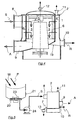
Die Figuren 3 und 4 dienen dazu, noch weitere Lösungen mit speziellen Details zu zeigen. So hat die Vorrichtung gemäß Fig. 3 eine geänderte Strömungsführung, indem der Gutstoff A aus dem Gutstoffraum 3 nicht wie in Fig. 1 nach unten, sondern nach oben abgeführt wird, d.h. dass der Gutstoffauslass 9' an der oberen Wand des Gutstoffraumes 3 zentral angeschlossen ist. Der so abgezogene Gutstoff A enthält dann neben den sortierten Fasern auch Luft, weshalb eine weitere Entlüftungsleitung entfallen kann. Die im Zulaufraum 4 nach außen abgeschleuderten Schwerteile werden durch einen senkrechten oder schrägen am Gehäuse 2 radial vorstehenden Schwerteilkanal 18 direkt nach unten zur Schwerteilschleuse 13 geführt. Diese Ausführung ("Schwerteilfalle") verhindert längeres Rotieren von Schwerteilen im Gehäuse und ist auch bei den in Figuren 1 und 4 gezeigten Sortierern möglich. Außerdem weist die Vorrichtung gemäß Fig. 3 eine Möglichkeit auf, um abgewiesene Schwerteile mit Hilfe einer Schräge 17 an einer unter dem Gutstoffraum 3 liegenden Fortsetzung des Zulaufraumes 4 besser in die Schwerteilschleuse 13 zu führen. Der Zulaufraum 4 wird oben durch eine Schräge 20 abgeschlossen, an deren höchster Stelle der Leichtstoffauslass 11' angeschlossen ist.Figures 3 and 4 serve to show even more solutions with specific details. Thus, the device according to FIG. 3 has a modified flow guidance in that the accept A from the accept
Der Drucksortierer in Fig. 4 ist mit einem Zulaufraum 4' versehen, dessen Querschnitt über die axiale Höhe im Wesentlichen konstant gehalten ist, da hier auf einen sich verjüngenden Abschnitt verzichtet wurde. Auch ein spezieller separater Leichtteilsammelraum oberhalb des Siebes 1 kann gegebenenfalls weggelassen werden, um Bauhöhe zu sparen. Die Leichtteile werden durch den Leichtteilauslass 11 sofort abgeleitet. Im unteren Teil des Zulaufraumes 4' befindet sich eine nach unten hin schräg verlaufende Abschlusswand 19, die die dort angelangten Schwerteile zusammen mit dem Rejekt R durch den Rejektauslass 10 aus dem Gehäuse herausführt. Zweckmäßigerweise ist der Rejektauslass 10 an der tiefsten Stelle angeschlossen. Ein weiterer Schwerteilauslass kann dann auch eingespart werden. Die Abschlusswand 19 kann eine bogenförmige Form haben.The pressure sorter in Fig. 4 is provided with an inlet space 4 ', whose cross section over the axial height is kept substantially constant, since it was dispensed with a tapered portion. Also, a special separate light parts collection space above the
Wie schon erwähnt, ist der bevorzugte Verwendungsfall dieser Vorrichtung die Vor- oder Grobsortierung von aufgelöstem Papierstoff. Das kann gemäß Fig. 5 typischerweise eine in einem Stofflöser 21 aus Altpapier P und Wasser W gebildete und durch ein grobes Pulpersieb 22 abgezogene Altpapiersuspension sein. Ein solches Pulpersieb 22 wird durch einen Rotor 23 freigehalten und hat üblicherweise Löcher mit einem Durchmesser zwischen 10 und 25 mm. Die durch diese abgezogene Altpapiersuspension wird ohne weitere Siebvorrichtung via Stoffpumpe 24 in den Zulauf 8 eines erfindungsgemäß ausgestalteten Drucksortierers gepumpt. Daher kann diese Suspension S mit einer größeren Menge von Störstoffen vermischt sein, die sich ohne weiteres an Sieböffnungen zurückhalten lassen, deren Durchmesser z.B. in einem Bereich zwischen 1 und 3 mm liegt.As already mentioned, the preferred use case of this device is the pre or coarse sorting of dissolved pulp. This may typically be a recovered paper pulp suspension formed in a
In anderen Anwendungen können solche verschmutzten Altpapiersuspensionen in einem Hochkonsistenz-Pulper oder in einer Auflösetrommel mit nachgeschalteter offener Siebvorrichtung, wie z.B. einer offenen Sortiertrommel, und Verdünnung hergestellt werden. Eine Auflösetrommel, die für das Verfahren geeignet ist, zeigt z.B. die
Claims (17)
- Pressure grader for screening pulp suspension (S) having at least one cylindrical or conical screen (1), which is inserted in a housing (2, 2'), its centre line being substantially vertical in the operating position, and which is provided with a large number of screen apertures, through which a part of the pulp suspension (S) supplied to a supply chamber (4, 4') through a tangential supply (8) can pass into an accepted stock chamber (3), to which an accepted stock outlet (9, 9') is connected, whilst another part of the suspension is rejected at the screen apertures and is discharged from the pressure grader separately as reject (R) through at least one reject outlet (10), wherein in the accepted stock chamber (3) a driven screen clearing device (5) is located, which is so driven that its speed of rotation is opposite to the tangential inflow direction at the supply (8), characterised in that a light-particle outlet (11, 11') is connected to the upper part of the supply chamber (4, 4').
- Pressure grader according to claim 1, characterised in that the pressure grader is provided with a screen (1), which separates the radially inner accepted stock chamber (3) from the radially outer supply chamber (4, 4').
- Pressure grader according to claim 1 or 2, characterised in that the supply chamber (4, 4') is connected to a heavy-particle outlet (7).
- Pressure grader according to claim 3, characterised in that the heavy-particle outlet (7) is connected to the lower part of the supply chamber (4, 4').
- Pressure grader according to claim 3 or 4, characterised in that an intermittently actuatable heavy-particle sluice (13) is connected to the heavy-particle outlet (7).
- Pressure grader according to one of the preceding claims, characterised in that the supply chamber (4) has a conically tapering section (15) between the supply (8) and the reject outlet (10).
- Pressure grader according to one of the preceding claims, characterised in that the supply (8) lies geometrically above the reject outlet (10).
- Pressure grader according to one of the preceding claims, characterised in that a ventilation line (12) is connected to the upper part of the accepted stock chamber (3).
- Pressure grader according to one of the preceding claims, characterised in that the screen clearing device (5) is so formed that, by relative motion, it can impart pressure and suction pulses in the direction of the screen (1) to the surrounding liquid.
- Pressure grader according to one of the preceding claims, characterised in that the supply chamber (4) is closed at the bottom by a slope (17), to whose lowest point the heavy-particle outlet (7) is connected.
- Pressure grader according to one of claims 1 to 9, characterised in that the supply chamber (4) is closed at the bottom by an obliquely extending closing wall (19), to whose lowest point the reject outlet is connected.
- Pressure grader according to one of the preceding claims, characterised in that the supply chamber (4) is closed at the top by a slope (20), to whose highest point the light-particle outlet (11') is connected.
- Use of a pressure grader according to one of the preceding claims, for cleaning a suspension produced from waste paper, which has been produced by dissolving in a dissolving drum and contains the unwanted materials, which can be retained at round screen apertures according to size, type and shape, the diameter of the apertures being larger than 1 mm, preferably larger than 3 mm.
- Use according to claim 13, characterised in that the suspension generated in a dissolving drum is graded and diluted in an open screening apparatus, in particular screening drum and is pumped into the pressure grader.
- Use of a pressure grader according to one of the preceding claims, for cleaning a suspension produced from waste paper, which has been produced by dissolving in a stock pulper (21) and which contains the unwanted materials, which can be retained on round screen apertures according to size, type and shape, the diameter of the apertures being larger than 1 mm, preferably larger than 3 mm.
- Use according to claim 15, characterised in that the suspension is pumped from the pulper (21) through a pulper screen (22) incorporated in the pulper direct into the pressure grader.
- Use according to claim 13, 14, 15 or 16, characterised in that the suspension (S) is passed into the pressure grader with a consistency of between 2% and 4%.
Applications Claiming Priority (2)
| Application Number | Priority Date | Filing Date | Title |
|---|---|---|---|
| DE102004025149A DE102004025149A1 (en) | 2004-05-21 | 2004-05-21 | Pressure sorted for sieving a pulp suspension |
| DE102004025149 | 2004-05-21 |
Publications (2)
| Publication Number | Publication Date |
|---|---|
| EP1598477A1 EP1598477A1 (en) | 2005-11-23 |
| EP1598477B1 true EP1598477B1 (en) | 2007-11-14 |
Family
ID=34934447
Family Applications (1)
| Application Number | Title | Priority Date | Filing Date |
|---|---|---|---|
| EP05006347A Expired - Lifetime EP1598477B1 (en) | 2004-05-21 | 2005-03-23 | Pressure screen for screening a fibrous suspension |
Country Status (8)
| Country | Link |
|---|---|
| US (1) | US20050258079A1 (en) |
| EP (1) | EP1598477B1 (en) |
| JP (1) | JP2005336698A (en) |
| KR (1) | KR20060048053A (en) |
| AT (1) | ATE378458T1 (en) |
| CA (1) | CA2508066A1 (en) |
| DE (2) | DE102004025149A1 (en) |
| ES (1) | ES2295994T3 (en) |
Families Citing this family (8)
| Publication number | Priority date | Publication date | Assignee | Title |
|---|---|---|---|---|
| ITUD20050063A1 (en) * | 2005-04-18 | 2006-10-19 | Pal Srl | EQUIPMENT AND PROCEDURE TO SEPARATE FINISH GRANULOMETRY PARTICLES FROM A NON-CONSISTENT MASS OF WOODEN MATERIAL |
| CN102191710B (en) * | 2011-04-06 | 2013-04-03 | 李�昊 | Improved intermittent type pressure pulp screening machine |
| DE102011115354B4 (en) | 2011-10-07 | 2017-01-05 | Telejet Kommunikations Gmbh | Navigation based on random patterns |
| FI126520B (en) * | 2016-03-16 | 2017-01-31 | Red Wire Oy | Process for screening and screening device |
| JP2019060056A (en) * | 2017-09-28 | 2019-04-18 | 相川鉄工株式会社 | Screen device and foreign matter separation method for screen device |
| CN110013955A (en) * | 2018-01-09 | 2019-07-16 | 宝山钢铁股份有限公司 | It is a kind of for filtering the filter device of bulky grain sundries in pulvis |
| CN112108237B (en) * | 2020-09-09 | 2021-12-21 | 湖南连心科技有限公司 | Powder coating particle control sieving equipment |
| JP7317153B1 (en) * | 2021-09-01 | 2023-07-28 | 三菱電機株式会社 | Foreign matter removal device |
Family Cites Families (6)
| Publication number | Priority date | Publication date | Assignee | Title |
|---|---|---|---|---|
| DE1231539B (en) * | 1960-07-08 | 1966-12-29 | Lamort E & M | Sifter for paper stock suspensions |
| FR1546515A (en) * | 1967-06-14 | 1968-11-22 | Lamort E & M | Apparatus for cleaning liquids containing suspended solids such as paper pulp |
| DE2830386C2 (en) * | 1978-07-11 | 1982-09-02 | Hermann Finckh, Maschinenfabrik GmbH & Co, 7417 Pfullingen | Process for sorting fiber suspensions and pressure sorters for carrying out the process |
| DE3911234A1 (en) * | 1989-04-07 | 1990-10-11 | Voith Gmbh J M | Screen |
| US5221437A (en) * | 1991-07-08 | 1993-06-22 | The Black Clawson Company | Screening apparatus for paper making stock |
| US20050115690A1 (en) * | 2003-11-25 | 2005-06-02 | Casella Waste Systems, Inc. | Methods for producing recycled pulp from waste paper |
-
2004
- 2004-05-21 DE DE102004025149A patent/DE102004025149A1/en not_active Ceased
-
2005
- 2005-03-23 EP EP05006347A patent/EP1598477B1/en not_active Expired - Lifetime
- 2005-03-23 DE DE502005001926T patent/DE502005001926D1/en not_active Expired - Lifetime
- 2005-03-23 AT AT05006347T patent/ATE378458T1/en not_active IP Right Cessation
- 2005-03-23 ES ES05006347T patent/ES2295994T3/en not_active Expired - Lifetime
- 2005-05-17 JP JP2005144441A patent/JP2005336698A/en active Pending
- 2005-05-18 US US11/131,358 patent/US20050258079A1/en not_active Abandoned
- 2005-05-20 CA CA002508066A patent/CA2508066A1/en not_active Abandoned
- 2005-05-21 KR KR1020050042754A patent/KR20060048053A/en not_active Withdrawn
Also Published As
| Publication number | Publication date |
|---|---|
| JP2005336698A (en) | 2005-12-08 |
| EP1598477A1 (en) | 2005-11-23 |
| US20050258079A1 (en) | 2005-11-24 |
| DE102004025149A1 (en) | 2005-12-15 |
| ATE378458T1 (en) | 2007-11-15 |
| CA2508066A1 (en) | 2005-11-21 |
| ES2295994T3 (en) | 2008-04-16 |
| KR20060048053A (en) | 2006-05-18 |
| DE502005001926D1 (en) | 2007-12-27 |
Similar Documents
| Publication | Publication Date | Title |
|---|---|---|
| EP0034780B1 (en) | Rotating sorter | |
| EP1215335B1 (en) | Pressure screen for cleaning paper pulp containing impurities | |
| WO2011076660A1 (en) | Method and screening device for screening a fiber suspension | |
| EP1598477B1 (en) | Pressure screen for screening a fibrous suspension | |
| DE2753413C3 (en) | Pressure sorter | |
| DE102011088102A1 (en) | Sieve for sifting a pulp suspension | |
| AT511367A2 (en) | Pulper arrangement and method for dissolving fiber material | |
| DE102004051327B4 (en) | Method for degassing and feeding a pulp suspension to a headbox and degassing | |
| WO2010124911A2 (en) | Method for treating a fiber suspension and screening devices for carrying out the same | |
| DE602004011346T2 (en) | Sorter for cleaning fiber suspensions | |
| DE69116513T2 (en) | Sorting device for removing knots from a liquid suspension of fibers and knots | |
| AT408770B (en) | SORTER FOR CLEANING A FIBER SUSPENSION | |
| EP1245724A2 (en) | Pressure screen for cleaning paper pulp containing impurities and its use | |
| AT15802U1 (en) | pressure screens | |
| EP1122358B1 (en) | Sorter for cleaning a fibre suspension | |
| DE3001448A1 (en) | PRINT SORTER | |
| EP1612326B1 (en) | Pressure screen for screening a fibrous suspension | |
| DE4308225C1 (en) | Process for sorting fiber suspension and screening device for carrying it out | |
| EP1749923B1 (en) | Apparatus for treating a fibrous suspension | |
| EP1394318A1 (en) | Pressure screen for screening a fibrous suspension | |
| DE19825669B4 (en) | Screening device for a soiled pulp suspension | |
| DE102004051887B3 (en) | Pressure material sorting system for sieving suspension of fibers in liquid has vessel with tangential entry and narrow gap leading to chamber inside cylindrical sieve containing rotor with paddles | |
| EP0427802B1 (en) | Appliance for sorting and deflaking fibre suspensions | |
| EP1710347A1 (en) | Process for pulping and cleaning of papermaking raw materials containing impurities | |
| DE20304303U1 (en) | Pressurised paper fibre suspension sorting assembly has rotating cylinder with a series of free standing surface-mounted blades set at different angles of attack |
Legal Events
| Date | Code | Title | Description |
|---|---|---|---|
| PUAI | Public reference made under article 153(3) epc to a published international application that has entered the european phase |
Free format text: ORIGINAL CODE: 0009012 |
|
| AK | Designated contracting states |
Kind code of ref document: A1 Designated state(s): AT BE BG CH CY CZ DE DK EE ES FI FR GB GR HU IE IS IT LI LT LU MC NL PL PT RO SE SI SK TR |
|
| AX | Request for extension of the european patent |
Extension state: AL BA HR LV MK YU |
|
| 17P | Request for examination filed |
Effective date: 20060523 |
|
| AKX | Designation fees paid |
Designated state(s): AT BE BG CH CY CZ DE DK EE ES FI FR GB GR HU IE IS IT LI LT LU MC NL PL PT RO SE SI SK TR |
|
| RAP1 | Party data changed (applicant data changed or rights of an application transferred) |
Owner name: VOITH PATENT GMBH |
|
| GRAP | Despatch of communication of intention to grant a patent |
Free format text: ORIGINAL CODE: EPIDOSNIGR1 |
|
| GRAS | Grant fee paid |
Free format text: ORIGINAL CODE: EPIDOSNIGR3 |
|
| GRAA | (expected) grant |
Free format text: ORIGINAL CODE: 0009210 |
|
| AK | Designated contracting states |
Kind code of ref document: B1 Designated state(s): AT BE BG CH CY CZ DE DK EE ES FI FR GB GR HU IE IS IT LI LT LU MC NL PL PT RO SE SI SK TR |
|
| REG | Reference to a national code |
Ref country code: GB Ref legal event code: FG4D Free format text: NOT ENGLISH |
|
| REG | Reference to a national code |
Ref country code: CH Ref legal event code: EP |
|
| GBT | Gb: translation of ep patent filed (gb section 77(6)(a)/1977) |
Effective date: 20071114 |
|
| REG | Reference to a national code |
Ref country code: IE Ref legal event code: FG4D Free format text: LANGUAGE OF EP DOCUMENT: GERMAN |
|
| REF | Corresponds to: |
Ref document number: 502005001926 Country of ref document: DE Date of ref document: 20071227 Kind code of ref document: P |
|
| REG | Reference to a national code |
Ref country code: SE Ref legal event code: TRGR |
|
| REG | Reference to a national code |
Ref country code: ES Ref legal event code: FG2A Ref document number: 2295994 Country of ref document: ES Kind code of ref document: T3 |
|
| PG25 | Lapsed in a contracting state [announced via postgrant information from national office to epo] |
Ref country code: NL Free format text: LAPSE BECAUSE OF FAILURE TO SUBMIT A TRANSLATION OF THE DESCRIPTION OR TO PAY THE FEE WITHIN THE PRESCRIBED TIME-LIMIT Effective date: 20071114 |
|
| NLV1 | Nl: lapsed or annulled due to failure to fulfill the requirements of art. 29p and 29m of the patents act | ||
| PG25 | Lapsed in a contracting state [announced via postgrant information from national office to epo] |
Ref country code: SI Free format text: LAPSE BECAUSE OF FAILURE TO SUBMIT A TRANSLATION OF THE DESCRIPTION OR TO PAY THE FEE WITHIN THE PRESCRIBED TIME-LIMIT Effective date: 20071114 Ref country code: BG Free format text: LAPSE BECAUSE OF FAILURE TO SUBMIT A TRANSLATION OF THE DESCRIPTION OR TO PAY THE FEE WITHIN THE PRESCRIBED TIME-LIMIT Effective date: 20080214 Ref country code: PL Free format text: LAPSE BECAUSE OF FAILURE TO SUBMIT A TRANSLATION OF THE DESCRIPTION OR TO PAY THE FEE WITHIN THE PRESCRIBED TIME-LIMIT Effective date: 20071114 Ref country code: IS Free format text: LAPSE BECAUSE OF FAILURE TO SUBMIT A TRANSLATION OF THE DESCRIPTION OR TO PAY THE FEE WITHIN THE PRESCRIBED TIME-LIMIT Effective date: 20080314 Ref country code: LT Free format text: LAPSE BECAUSE OF FAILURE TO SUBMIT A TRANSLATION OF THE DESCRIPTION OR TO PAY THE FEE WITHIN THE PRESCRIBED TIME-LIMIT Effective date: 20071114 |
|
| ET | Fr: translation filed | ||
| PG25 | Lapsed in a contracting state [announced via postgrant information from national office to epo] |
Ref country code: CZ Free format text: LAPSE BECAUSE OF FAILURE TO SUBMIT A TRANSLATION OF THE DESCRIPTION OR TO PAY THE FEE WITHIN THE PRESCRIBED TIME-LIMIT Effective date: 20071114 Ref country code: DK Free format text: LAPSE BECAUSE OF FAILURE TO SUBMIT A TRANSLATION OF THE DESCRIPTION OR TO PAY THE FEE WITHIN THE PRESCRIBED TIME-LIMIT Effective date: 20071114 |
|
| PG25 | Lapsed in a contracting state [announced via postgrant information from national office to epo] |
Ref country code: SK Free format text: LAPSE BECAUSE OF FAILURE TO SUBMIT A TRANSLATION OF THE DESCRIPTION OR TO PAY THE FEE WITHIN THE PRESCRIBED TIME-LIMIT Effective date: 20071114 Ref country code: RO Free format text: LAPSE BECAUSE OF FAILURE TO SUBMIT A TRANSLATION OF THE DESCRIPTION OR TO PAY THE FEE WITHIN THE PRESCRIBED TIME-LIMIT Effective date: 20071114 |
|
| PLBE | No opposition filed within time limit |
Free format text: ORIGINAL CODE: 0009261 |
|
| STAA | Information on the status of an ep patent application or granted ep patent |
Free format text: STATUS: NO OPPOSITION FILED WITHIN TIME LIMIT |
|
| BERE | Be: lapsed |
Owner name: VOITH PATENT G.M.B.H. Effective date: 20080331 |
|
| PG25 | Lapsed in a contracting state [announced via postgrant information from national office to epo] |
Ref country code: PT Free format text: LAPSE BECAUSE OF FAILURE TO SUBMIT A TRANSLATION OF THE DESCRIPTION OR TO PAY THE FEE WITHIN THE PRESCRIBED TIME-LIMIT Effective date: 20080414 |
|
| REG | Reference to a national code |
Ref country code: IE Ref legal event code: FD4D |
|
| 26N | No opposition filed |
Effective date: 20080815 |
|
| PG25 | Lapsed in a contracting state [announced via postgrant information from national office to epo] |
Ref country code: MC Free format text: LAPSE BECAUSE OF NON-PAYMENT OF DUE FEES Effective date: 20080331 Ref country code: IE Free format text: LAPSE BECAUSE OF FAILURE TO SUBMIT A TRANSLATION OF THE DESCRIPTION OR TO PAY THE FEE WITHIN THE PRESCRIBED TIME-LIMIT Effective date: 20071114 |
|
| PG25 | Lapsed in a contracting state [announced via postgrant information from national office to epo] |
Ref country code: GR Free format text: LAPSE BECAUSE OF FAILURE TO SUBMIT A TRANSLATION OF THE DESCRIPTION OR TO PAY THE FEE WITHIN THE PRESCRIBED TIME-LIMIT Effective date: 20080215 Ref country code: EE Free format text: LAPSE BECAUSE OF FAILURE TO SUBMIT A TRANSLATION OF THE DESCRIPTION OR TO PAY THE FEE WITHIN THE PRESCRIBED TIME-LIMIT Effective date: 20071114 |
|
| PG25 | Lapsed in a contracting state [announced via postgrant information from national office to epo] |
Ref country code: BE Free format text: LAPSE BECAUSE OF NON-PAYMENT OF DUE FEES Effective date: 20080331 |
|
| PG25 | Lapsed in a contracting state [announced via postgrant information from national office to epo] |
Ref country code: CY Free format text: LAPSE BECAUSE OF FAILURE TO SUBMIT A TRANSLATION OF THE DESCRIPTION OR TO PAY THE FEE WITHIN THE PRESCRIBED TIME-LIMIT Effective date: 20071114 |
|
| REG | Reference to a national code |
Ref country code: CH Ref legal event code: PL |
|
| PG25 | Lapsed in a contracting state [announced via postgrant information from national office to epo] |
Ref country code: LI Free format text: LAPSE BECAUSE OF NON-PAYMENT OF DUE FEES Effective date: 20090331 Ref country code: CH Free format text: LAPSE BECAUSE OF NON-PAYMENT OF DUE FEES Effective date: 20090331 |
|
| PGFP | Annual fee paid to national office [announced via postgrant information from national office to epo] |
Ref country code: ES Payment date: 20100324 Year of fee payment: 6 |
|
| PGFP | Annual fee paid to national office [announced via postgrant information from national office to epo] |
Ref country code: FI Payment date: 20100312 Year of fee payment: 6 Ref country code: FR Payment date: 20100402 Year of fee payment: 6 Ref country code: IT Payment date: 20100325 Year of fee payment: 6 |
|
| PGFP | Annual fee paid to national office [announced via postgrant information from national office to epo] |
Ref country code: AT Payment date: 20100311 Year of fee payment: 6 Ref country code: GB Payment date: 20100322 Year of fee payment: 6 |
|
| PG25 | Lapsed in a contracting state [announced via postgrant information from national office to epo] |
Ref country code: LU Free format text: LAPSE BECAUSE OF NON-PAYMENT OF DUE FEES Effective date: 20080323 Ref country code: HU Free format text: LAPSE BECAUSE OF FAILURE TO SUBMIT A TRANSLATION OF THE DESCRIPTION OR TO PAY THE FEE WITHIN THE PRESCRIBED TIME-LIMIT Effective date: 20080515 |
|
| PG25 | Lapsed in a contracting state [announced via postgrant information from national office to epo] |
Ref country code: TR Free format text: LAPSE BECAUSE OF FAILURE TO SUBMIT A TRANSLATION OF THE DESCRIPTION OR TO PAY THE FEE WITHIN THE PRESCRIBED TIME-LIMIT Effective date: 20071114 |
|
| PGFP | Annual fee paid to national office [announced via postgrant information from national office to epo] |
Ref country code: DE Payment date: 20100324 Year of fee payment: 6 |
|
| PGFP | Annual fee paid to national office [announced via postgrant information from national office to epo] |
Ref country code: SE Payment date: 20100312 Year of fee payment: 6 |
|
| REG | Reference to a national code |
Ref country code: SE Ref legal event code: EUG |
|
| GBPC | Gb: european patent ceased through non-payment of renewal fee |
Effective date: 20110323 |
|
| PG25 | Lapsed in a contracting state [announced via postgrant information from national office to epo] |
Ref country code: AT Free format text: LAPSE BECAUSE OF NON-PAYMENT OF DUE FEES Effective date: 20110323 Ref country code: FI Free format text: LAPSE BECAUSE OF NON-PAYMENT OF DUE FEES Effective date: 20110323 |
|
| REG | Reference to a national code |
Ref country code: FR Ref legal event code: ST Effective date: 20111130 |
|
| PG25 | Lapsed in a contracting state [announced via postgrant information from national office to epo] |
Ref country code: FR Free format text: LAPSE BECAUSE OF NON-PAYMENT OF DUE FEES Effective date: 20110331 Ref country code: DE Free format text: LAPSE BECAUSE OF NON-PAYMENT OF DUE FEES Effective date: 20111001 |
|
| PG25 | Lapsed in a contracting state [announced via postgrant information from national office to epo] |
Ref country code: GB Free format text: LAPSE BECAUSE OF NON-PAYMENT OF DUE FEES Effective date: 20110323 Ref country code: IT Free format text: LAPSE BECAUSE OF NON-PAYMENT OF DUE FEES Effective date: 20110323 |
|
| REG | Reference to a national code |
Ref country code: ES Ref legal event code: FD2A Effective date: 20120423 |
|
| REG | Reference to a national code |
Ref country code: DE Ref legal event code: R119 Ref document number: 502005001926 Country of ref document: DE Effective date: 20111001 |
|
| PG25 | Lapsed in a contracting state [announced via postgrant information from national office to epo] |
Ref country code: ES Free format text: LAPSE BECAUSE OF NON-PAYMENT OF DUE FEES Effective date: 20110324 |
|
| PG25 | Lapsed in a contracting state [announced via postgrant information from national office to epo] |
Ref country code: SE Free format text: LAPSE BECAUSE OF NON-PAYMENT OF DUE FEES Effective date: 20110324 |