EP3851335A1 - Élément de châssis d'automobile et véhicule électrique - Google Patents
Élément de châssis d'automobile et véhicule électrique Download PDFInfo
- Publication number
- EP3851335A1 EP3851335A1 EP19876878.0A EP19876878A EP3851335A1 EP 3851335 A1 EP3851335 A1 EP 3851335A1 EP 19876878 A EP19876878 A EP 19876878A EP 3851335 A1 EP3851335 A1 EP 3851335A1
- Authority
- EP
- European Patent Office
- Prior art keywords
- groove part
- top plate
- vertical
- frame member
- automotive frame
- Prior art date
- Legal status (The legal status is an assumption and is not a legal conclusion. Google has not performed a legal analysis and makes no representation as to the accuracy of the status listed.)
- Pending
Links
Images


Classifications
-
- B—PERFORMING OPERATIONS; TRANSPORTING
- B62—LAND VEHICLES FOR TRAVELLING OTHERWISE THAN ON RAILS
- B62D—MOTOR VEHICLES; TRAILERS
- B62D21/00—Understructures, i.e. chassis frame on which a vehicle body may be mounted
- B62D21/15—Understructures, i.e. chassis frame on which a vehicle body may be mounted having impact absorbing means, e.g. a frame designed to permanently or temporarily change shape or dimension upon impact with another body
- B62D21/157—Understructures, i.e. chassis frame on which a vehicle body may be mounted having impact absorbing means, e.g. a frame designed to permanently or temporarily change shape or dimension upon impact with another body for side impacts
-
- B—PERFORMING OPERATIONS; TRANSPORTING
- B60—VEHICLES IN GENERAL
- B60R—VEHICLES, VEHICLE FITTINGS, OR VEHICLE PARTS, NOT OTHERWISE PROVIDED FOR
- B60R16/00—Electric or fluid circuits specially adapted for vehicles and not otherwise provided for; Arrangement of elements of electric or fluid circuits specially adapted for vehicles and not otherwise provided for
- B60R16/02—Electric or fluid circuits specially adapted for vehicles and not otherwise provided for; Arrangement of elements of electric or fluid circuits specially adapted for vehicles and not otherwise provided for electric constitutive elements
- B60R16/04—Arrangement of batteries
-
- B—PERFORMING OPERATIONS; TRANSPORTING
- B60—VEHICLES IN GENERAL
- B60R—VEHICLES, VEHICLE FITTINGS, OR VEHICLE PARTS, NOT OTHERWISE PROVIDED FOR
- B60R19/00—Wheel guards; Radiator guards, e.g. grilles; Obstruction removers; Fittings damping bouncing force in collisions
- B60R19/02—Bumpers, i.e. impact receiving or absorbing members for protecting vehicles or fending off blows from other vehicles or objects
- B60R19/18—Bumpers, i.e. impact receiving or absorbing members for protecting vehicles or fending off blows from other vehicles or objects characterised by the cross-section; Means within the bumper to absorb impact
-
- B—PERFORMING OPERATIONS; TRANSPORTING
- B62—LAND VEHICLES FOR TRAVELLING OTHERWISE THAN ON RAILS
- B62D—MOTOR VEHICLES; TRAILERS
- B62D21/00—Understructures, i.e. chassis frame on which a vehicle body may be mounted
- B62D21/15—Understructures, i.e. chassis frame on which a vehicle body may be mounted having impact absorbing means, e.g. a frame designed to permanently or temporarily change shape or dimension upon impact with another body
-
- B—PERFORMING OPERATIONS; TRANSPORTING
- B62—LAND VEHICLES FOR TRAVELLING OTHERWISE THAN ON RAILS
- B62D—MOTOR VEHICLES; TRAILERS
- B62D25/00—Superstructure or monocoque structure sub-units; Parts or details thereof not otherwise provided for
- B62D25/02—Side panels
- B62D25/025—Side sills thereof
-
- B—PERFORMING OPERATIONS; TRANSPORTING
- B60—VEHICLES IN GENERAL
- B60R—VEHICLES, VEHICLE FITTINGS, OR VEHICLE PARTS, NOT OTHERWISE PROVIDED FOR
- B60R19/00—Wheel guards; Radiator guards, e.g. grilles; Obstruction removers; Fittings damping bouncing force in collisions
- B60R19/02—Bumpers, i.e. impact receiving or absorbing members for protecting vehicles or fending off blows from other vehicles or objects
- B60R19/18—Bumpers, i.e. impact receiving or absorbing members for protecting vehicles or fending off blows from other vehicles or objects characterised by the cross-section; Means within the bumper to absorb impact
- B60R2019/1806—Structural beams therefor, e.g. shock-absorbing
- B60R2019/1813—Structural beams therefor, e.g. shock-absorbing made of metal
-
- B—PERFORMING OPERATIONS; TRANSPORTING
- B62—LAND VEHICLES FOR TRAVELLING OTHERWISE THAN ON RAILS
- B62D—MOTOR VEHICLES; TRAILERS
- B62D29/00—Superstructures, understructures, or sub-units thereof, characterised by the material thereof
- B62D29/008—Superstructures, understructures, or sub-units thereof, characterised by the material thereof predominantly of light alloys, e.g. extruded
Definitions
- the present disclosure relates to an automotive frame member which exhibits a high energy absorption efficiency, for example, in a collision of an automotive or the like.
- Patent Document 1 discloses that a bulkhead having a substantially U-shaped cross section is provided between a side sill and a cross member.
- the bulkhead in Patent Document 1 is configured by a front surface part, a rear side surface part, and a flange, and a recessed portion is provided to the front surface part and the rear side surface part.
- Patent Document 2 discloses an impact absorbing member in which a deformation facilitating means in a bellows shape is provided to a hollow member.
- Patent Document 3 discloses an absorber made of metal in which recessed or protruding beads are formed on a vertical wall of a hat member.
- the vehicle body structure in Patent Document 1 is not a structure which is intended to suppress the buckling of the side sill itself, so that there is room for improvement in terms of the improvement of the energy absorption performance realized by taking advantage of the material strength. Further, when the present inventors performed a simulation regarding the impact absorbing member in Patent Document 2, there remained a lot of parts which were not subjected to plastic deformation in the impact absorbing member, and thus there is room for improvement in terms of the improvement of the energy absorption performance realized by taking advantage of the material strength.
- the absorber in Patent Document 3 is one intended to protect a leg part of a pedestrian when a collision between the pedestrian and an automotive occurs, and thus there is room for improvement in terms of the improvement of the energy absorption performance on the vehicle body side.
- the present disclosure has been made in view of the above-described problems, and an object thereof is to improve an energy absorption efficiency (a mass efficiency of absorbed energy) of an automotive frame member.
- an automotive frame member including a hat member and a closing plate
- the hat member includes a top plate, two vertical walls, and two flanges
- the two vertical walls are positioned between the top plate and the flanges, respectively, the two vertical walls face each other, the two flanges are respectively joined to the closing plate
- each of the two vertical walls includes plural groove parts extending in a direction vertical to a longitudinal direction of the hat member
- the groove part includes a bottom surface and two side surfaces, the two side surfaces face each other, the two side surfaces are positioned on both sides of the bottom surface, and a width a of the groove part and a depth b of the groove part in a cross section parallel to the top plate, and a height c of the vertical wall in a direction vertical to the top plate satisfy relations of 0.2 ⁇ a/c ⁇ 0.3 and 0.2 ⁇ b/c ⁇ 0.3.
- An aspect of the present disclosure is an automotive frame member including a hollow member, in which the hollow member includes a top plate and two vertical walls, the two vertical walls are respectively adjacent to the top plate, the two vertical walls face each other, each of the two vertical walls includes plural groove parts extending in a direction vertical to a longitudinal direction of the hollow member, the groove part includes a bottom surface and two side surfaces, the two side surfaces face each other, the two side surfaces are positioned on both sides of the bottom surface, and a width a of the groove part and a depth b of the groove part in a cross section parallel to the top plate, and a height c of the vertical wall in a direction vertical to the top plate satisfy relations of 0.2 ⁇ a/c ⁇ 0.3 and 0.2 ⁇ b/c ⁇ 0.3.
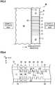
- FIG 1 is a view illustrating a schematic configuration of an automotive frame member 1 in a first embodiment.
- the automotive frame member 1 is a member that receives a bending load, such as a side sill or a bumper beam.
- the automotive frame member 1 of the first embodiment has a hat member 10 being a member whose cross section vertical to a member longitudinal direction (Y direction in FIG. 1 ) has a hat shape, and a flat closing plate 20 being a bottom plate that is joined to the hat member 10. Note that an X direction, the Y direction, and a Z direction illustrated in FIG.
- the X direction is a vehicle height direction
- the Y direction is a vehicle length direction
- the Z direction is a vehicle width direction
- the X direction is the vehicle height direction
- the Y direction is the vehicle width direction
- the Z direction is the vehicle length direction.
- the hat member 10 has a top plate 11, two vertical walls 12 connected to the top plate 11, and two flanges 13 connected to the vertical walls 12.
- the two vertical walls 12 are positioned between the top plate 11 and the flanges 13, respectively, and the two vertical walls 12 face each other.
- the two flanges 13 of the hat member 10 and the closing plate 20 are joined, to thereby configure the automotive frame member 1.
- the hat member 10 is formed of a steel product with tensile strength of 440 to 1500 MPa, for example, a material of the hat member 10 is not particularly limited, and the hat member 10 may be, for example, an aluminum alloy member, a magnesium alloy member, or the like.
- the closing plate 20 is formed of a steel product with tensile strength of 440 to 1500 MPa, for example, a material of the closing plate 20 is not particularly limited, and the closing plate 20 may be, for example, an aluminum alloy member, a magnesium alloy member, or the like.
- the top plate 11 of the hat member 10 may be disposed on a vehicle-exterior side or a vehicle-interior side with respect to the closing plate 20.
- the top plate 11 is preferably disposed on the vehicle-exterior side with respect to the closing plate 20. This is because, if a flange of the hat member is positioned on the vehicle-exterior side, the flange and a door interfere with each other, which prevents the door from closing. Further, it is preferable to apply the present disclosure to an electric vehicle.
- FIG 3 is a view illustrating a periphery of a side sill 41 in a cross section vertical to a vehicle height direction of an electric vehicle 40.
- the closing plate 20 is adjacent to a battery 42 mounted on a floor panel (not illustrated), and the top plate 11 is disposed on the vehicle-exterior side, out of the vehicle-exterior side and the vehicle-interior side. Note that in the present embodiment and embodiments to be described later, the top plate 11 is disposed on the vehicle-exterior side, out of the vehicle-exterior side and the vehicle-interior side.
- the hat member 10 of the first embodiment has a groove part 31 extending in a direction vertical to a member longitudinal direction.
- the groove part 31 is preferably formed so as to be provided continuously from a ridge line portion 14 to a ridge line portion 15, namely, it is preferably formed from a vehicle-interior-side end portion to a vehicle-exterior-side end portion of the vertical wall 12, as illustrated in FIG. 1 and FIG. 4 to FIG 6 .
- the groove part 31 is provided to both of a pair of vertical walls 12.
- a molding method of the groove part 31 is not particularly limited, and the molding is performed in a manner that, for example, after molding the hat member 10, presswork is repeatedly performed to gradually increase a depth of the groove part 31.
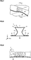
- a place where the groove part 31 is formed as illustrated in FIG. 4 is referred to as a "groove formation place 30".
- the top plate 11 at the groove formation place 30 is referred to as a "groove part top plate 32”
- the vertical wall 12 at the groove formation place 30 is referred to as a "groove part vertical wall 33”
- the flange 13 at the groove formation place 30 is referred to as a "groove part flange 34".
- the groove part top plate 32 is positioned within a plane same as that of the top plate 11 of a part except for the groove formation place 30, and the groove part flange 34 is positioned within a plane same as that of the flange 13 of a part except for the groove formation place 30.
- the groove part vertical wall 33 of the first embodiment has a bottom surface 31a of the groove part 31 being a surface parallel to the vertical wall 12 of a part except for the groove formation place 30, and side surfaces 31b being a pair of flat surfaces connecting the vertical wall 12 of a part except for the groove formation place 30 and the bottom surface 31a of the groove part 31.
- the groove part 31 includes the bottom surface 31a and the two side surfaces 31b, and the two side surfaces 31b face each other and are positioned on both sides of the bottom surface 31a.
- a plurality of the groove formation places 30 is provided with an interval provided therebetween along the member longitudinal direction of the hat member 10.
- the two vertical walls 12 include a plurality of the groove parts 31 along the member longitudinal direction of the hat member 10.
- a region in which the groove formation places 30 exist is only a middle part of the hat member 10 in the member longitudinal direction, but the groove formation places 30 may also be provided along the entire region of the hat member 10 in the member longitudinal direction, for example. Since the plural groove formation places 30 are provided, the vertical wall 12 positioned between the adjacent groove formation places 30 is shaped so as to protrude from the bottom surface 31 a of the groove part 31.
- the automotive frame member 1 of the first embodiment is configured as described above.
- this automotive frame member 1 when a collision occurs, a load is partially applied from the Z direction and moment is produced, resulting in that bending deformation occurs.
- the groove part 31 of the hat member 10 is provided to not only the vertical wall 12 but also the ridge line portion 14 between the vertical wall 12 and the top plate 11 and the ridge line portion 15 between the vertical wall 12 and the flange 13, so that when compared to a case where no groove part 31 is provided to each of the ridge line portions 14, 15, surface rigidity of the top plate 11 is increased, and it is possible to increase a load required for the deformation of the automotive frame member 1.
- the groove part 31 is shaped to have three flat surfaces, namely, the bottom surface 31a and the two side surfaces 31b of the groove part 31, so that it is possible to further increase the surface rigidity of the top plate 11, and it is possible to further increase the load required for the deformation of the automotive frame member 1. Because of these actions, it is possible to improve the energy absorption performance in the automotive frame member 1 of the first embodiment. Further, the automotive frame member 1 of the first embodiment does not have a structure in which a reinforcing member is newly added, and thus it is possible to improve a mass efficiency regarding the energy absorption performance.
- an out-of-plane bending mode is a mode in which main deformation is deformation in which the vertical wall 12 of the hat member 10 is bent in an out-of-plane direction in a cross section vertical to the member longitudinal direction.
- an in-plane bending mode is a mode in which main deformation is deformation in which the vertical wall 12 of the hat member 10 is bent along the member longitudinal direction, and thus deformation of the vertical wall 12 in the out-of-plane direction in the cross section vertical to the member longitudinal direction is small.
- an axial crush mode is a mode in which the vertical wall 12 of the hat member 10 crushes at short intervals in the cross section vertical to the member longitudinal direction, and deformation in a bellows shape occurs as a whole.
- the automotive frame member 1 is preferably deformed at the axial crush mode.
- a width of the groove part 31 and a depth of the groove part 31 in a cross section parallel to the top plate 11 of the hat member 10 are defined as “a” and “b”, respectively, as illustrated in FIG 4
- a height of the vertical wall 12 in a direction vertical to the top plate 11 of the hat member 10 is defined as "c”, as illustrated in FIG. 6 .
- the width a of the groove part 31 is a distance between the side surfaces 31b which face each other, in the member longitudinal direction of the hat member 10 (Y direction).
- the depth b of the groove part 31 is a length from the vertical wall 12 to the bottom surface 31a of the groove part 31 in a direction vertical to the member longitudinal direction of the hat member 10 (X direction), in the cross section parallel to the top plate 11 of the hat member 10.
- the height c of the vertical wall 12 is a length from the flange 13 to the top plate 11 in a direction vertical to the member longitudinal direction of the hat member 10 (Z direction). Note that in the first embodiment, the height c of the vertical wall 12 is equal to a height from the groove part flange 34 to the groove part top plate 32.
- the width a of the groove part 31, the depth b of the groove part 31, and the height c of the vertical wall 12 of the hat member 10 preferably satisfy relations of 0.2 ⁇ a/c ⁇ 0.3 and 0.2 ⁇ b/c ⁇ 0.3.
- this numeric value range is satisfied, the deformation of the automotive frame member 1 is likely to become one of the axial crush mode, as in examples to be described later, and a load required for the deformation becomes large in a stable manner from the initial stage of collision to the latter stage of collision. This enables to further improve the energy absorption performance.
- an interval d between the adjacent groove parts 31 is preferably 50 mm or less.
- the interval d between the groove parts 31 is 50 mm or less, the deformation in the axial crush mode is likely to occur, which enables to improve the energy absorption efficiency.
- an angle ⁇ 1 made by the bottom surface 31a of the groove part 31 and the side surface 31b of the groove part 31 is preferably 90 to 95 degrees, and it is more preferably a vertical angle.
- an angle ⁇ 2 made by the groove part vertical wall 33 and the groove part flange 34 is preferably 90 to 100 degrees as illustrated in FIG 6 , and it is more preferably a vertical angle.
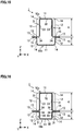
- the groove part 31 does not extend to the ridge line portion 14 of the hat member 10.
- one end of the groove part 31 extends to a vehicle-interior-side end portion of the vertical wall 12 (the ridge line portion 15 in an example of FIG 14 ), but the other end of the groove part 31 does not extend to a vehicle-exterior-side end portion of the vertical wall 12 (the ridge line portion 14 in the example of FIG 14 ).
- the groove part 31 having such a shape, when the width a of the groove part 31, the depth b of the groove part 31, and the height c of the vertical wall 12 of the hat member 10 satisfy the relations of 0.2 ⁇ a/c ⁇ 0.3 and 0.2 ⁇ b/c ⁇ 0.3, it becomes easy to cause the deformation in the axial crush mode, resulting in that the energy absorption efficiency can be improved.
- FIG. 14 is a view illustrating an example of shape of the groove part 31.
- An automotive frame member 1 in the example of FIG. 14 has a structure in which although one end of the groove part 31 extends to the vehicle-exterior-side end portion of the vertical wall 12 (the ridge line portion 14 in the example of FIG. 14 ), the other end of the groove part 31 does not extend to the vehicle-interior-side end portion of the vertical wall 12 (the ridge line portion 15 in the example of FIG. 14 ), the structure being different from that of the example in FIG. 13 .
- the automotive frame member 1 having the structure as illustrated in FIG 13 described above can improve the energy absorption efficiency more than the automotive frame member 1 having the structure as illustrated in FIG 14 .
- a buckling region extends from a portion where buckling occurs first, of the vertical wall 12, which is set as a starting point, toward the vehicle-interior-side end portion of the vertical wall 12. For this reason, it is advantageous to set the portion to be buckled first to the vehicle-exterior side of the vertical wall 12, in terms of improvement of the energy absorption efficiency. There are two reasons for that. The first reason is that the closer the portion to be buckled first to the vehicle-exterior-side end portion of the vertical wall 12, the larger the region to be deformed in a bellows shape.
- the second reason is that when the vertical wall 12 on the vehicle-interior side is buckled precedently, a deviation between the extending direction of the groove part 31 on the vehicle-exterior side and the impact-input direction becomes large, resulting in that the deformation in the axial crush mode becomes difficult to occur.
- the groove part 31 desirably extends to the vehicle-interior-side end portion of the vertical wall 12.
- the portion to be buckled first is a portion where no groove part 31 is provided. The reason why the buckling occurs first at the portion where no groove part 31 is provided, is because when there is no groove part 31, a deformation resistance is small.
- the groove part 31 extends to the vehicle-interior-side end portion of the vertical wall 12 (the ridge line portion 15 in the example of FIG. 13 ), and no groove part 31 is formed on the vehicle-exterior-side end portion of the vertical wall 12 (the ridge line portion 14 in the example of FIG. 13 ). Accordingly, when an impact load is input into the automotive frame member 1 in FIG. 13 , buckling is likely to occur in the vicinity of the vehicle-exterior-side end portion of the vertical wall 12 (the ridge line portion 14 in the example of FIG 13 ).
- the automotive frame member 1 in FIG 14 buckling is likely to occur in the vicinity of the vehicle-interior-side end portion of the vertical wall 12 (the ridge line portion 15 in the example of FIG 14 ). Therefore, the automotive frame member 1 having the structure as illustrated in FIG. 13 can secure a large region to be deformed in a bellows shape when compared to the automotive frame member 1 having the structure as illustrated in FIG 14 , resulting in that the energy absorption efficiency can be improved.
- the automotive frame member 1 in the second embodiment since the groove part 31 is not formed on the ridge line portion 14 being one of the ridge line portion 14 and the ridge line portion 15, it is easy to mold the hat member 10 when compared to the automotive frame member 1 of the first embodiment.
- the automotive frame member 1 of the second embodiment is a member capable of realizing both the energy absorption efficiency and the moldability at a high level.
- a length e of the groove part 31 in a direction vertical to the top plate 11 of the hat member 10 is preferably a length of 80% or more of the height c of the vertical wall 12 of the hat member 10. This makes it easy to cause the deformation in the axial crush mode when an impact load is input, resulting in that the energy absorption efficiency can be improved.
- the length e of the groove part 31 is a length, at the groove formation place 30, from the flange 13 to an R stop of the vertical wall 12 on the groove part 31 side. From a viewpoint of further improving the energy absorption efficiency, the length e of the groove part 31 is more preferably a length of 90% or more, and still more preferably a length of 95% or more of the height c of the vertical wall 12.
- a mating member of the hat member 10 is the closing plate 20.
- a mating member is also a hat member.
- the hat member described in the first embodiment (the upper member in FIG 15 ) is referred to as a "first hat member 10a”
- a hat member to be a mating member of the first hat member 10a (the lower member in FIG. 15 ) is referred to as a "second hat member 10b”.
- the second hat member 10b also has the top plate 11, the pair of vertical walls 12 connected to the top plate 11, and the flanges 13 connected to the vertical walls 12, similarly to the first hat member 10a.
- the first hat member 10a and the second hat member 10b are joined by their flanges 13, to thereby configure the automotive frame member 1.
- the groove part 31 of the first hat member 10a has the bottom surface 31a and the pair of side surfaces 31b when seen from a direction vertical to the top plate 11, as illustrated in FIG 4 , and the groove part 31 is provided from the ridge line portion 14 to the ridge line portion 15, as illustrated in FIG 15 . For this reason, it is possible to improve the energy absorption efficiency.
- the second hat member 10b may also be provided with the groove part 31, similarly to the first hat member 10a. This makes it possible to further improve the energy absorption efficiency.
- a ratio between the width a of the groove part 31, and a sum c of a height ci of the first hat member 10a and a height c 2 of the second hat member 10b (a/c) is preferably 0.2 to 0.3
- a ratio between the depth b of the groove part 31, and the sum c of the height ci of the first hat member 10a and the height c 2 of the second hat member 10b (b/c) is preferably 0.2 to 0.3.
- the angle ⁇ 1 made by the bottom surface 31a of the groove part 31 and the side surface 31b of the groove part 31 is preferably 90 to 95 degrees, and it is more preferably a vertical angle.
- the angle ⁇ 2 made by the groove part vertical wall 33 and the groove part flange 34 is preferably 90 to 100 degrees, and it is more preferably a vertical angle.
- a ratio between the height c 2 of the second hat member 10b and the height ci of the first hat member 10a (c 2 /c 1 ) is preferably 0.25 or less.
- the c 2 /c 1 is more preferably 0.2 or less, and still more preferably 0.1 or less. Specifically, the smaller the c 2 /c 1 , the more preferable.
- an automotive frame member 1 of a fourth embodiment is configured by a square tubular hollow member 2, as illustrated in FIG. 17 and FIG 18 .
- the hollow member 2 has a top plate 11, two vertical walls 12 connected to the top plate 11, and a bottom plate 16 connected to the two vertical walls 12.
- the two vertical walls 12 are positioned between the top plate 11 and the bottom plate 16, respectively, and the two vertical walls 12 face each other. Further, the top plate 11 and the bottom plate 16 also face each other.
- a material of the hollow member 2 is not particularly limited, and it is, for example, a steel product of an aluminum alloy member, a magnesium alloy member, or the like.
- the automotive frame member 1 of the fourth embodiment is a member configuring the side sill 41 of the electric vehicle 40, for example, the top plate 16 of the hollow member 2 is adjacent to the battery 42 mounted on the floor panel (not illustrated), similarly to the example of FIG. 3 .
- the automotive frame member 1 of the fourth embodiment has plural groove parts 31 extending in a direction vertical to a member longitudinal direction of the hollow member 2, similarly to the first to third embodiments.
- the groove part 31 is preferably formed so as to be provided continuously from a ridge line portion 14 to a ridge line portion 17, namely, it is preferably formed from a vehicle-interior-side end portion to a vehicle-exterior-side end portion of the vertical wall 12.
- the groove part 31 is provided to both of a pair of vertical walls 12.
- a molding method of the groove part 31 is not particularly limited, and the molding is performed in a manner that, after forming a square tubular hollow member through extrusion molding, for example, presswork is repeatedly performed to gradually increase a depth of the groove part 31. Further, the groove part 31 may also be formed by hydroforming, for example.
- the two vertical walls 12 include the plural groove parts 31 along the member longitudinal direction of the hollow member 2.
- the top plate 11 at the groove formation place 30 is referred to as a "groove part top plate 32”
- the vertical wall 12 at the groove formation place 30 is referred to as a "groove part vertical wall 33”
- the bottom plate 16 at the groove formation place 30 is referred to as a "groove part bottom plate 35”.
- the groove part top plate 32 is positioned within a plane same as that of the top plate 11 of a part except for the groove formation place 30, and the groove part bottom plate 35 is positioned within a plane same as that of the bottom plate 16 of a part except for the groove formation place 30.
- a shape of the groove part 31 in a plan view is similar to that of the first to third embodiments.
- the groove part vertical wall 33 has a bottom surface 31a of the groove part 31 being a surface parallel to the vertical wall 12 of a part except for the groove formation place 30, and side surfaces 31b being a pair of flat surfaces connecting the vertical wall 12 of a part except for the groove formation place 30 and the bottom surface 31a of the groove part 31.
- the groove part 31 includes the bottom surface 31a and the two side surfaces 31b, and the two side surfaces 31b face each other and are positioned on both sides of the bottom surface 31a.
- the automotive frame member 1 of the fourth embodiment is configured as described above. Also in the automotive frame member 1 of the fourth embodiment, the width a of the groove part 31 ( FIG 4 ), the depth b of the groove part 31 ( FIG. 4 ), and a height c of the vertical wall 12 of the hollow member 2 ( FIG 18 ) satisfy relations of 0.2 ⁇ a/c ⁇ 0.3 and 0.2 ⁇ b/c ⁇ 0.3. For this reason, it is possible to improve the energy absorption efficiency, similarly to the automotive frame member 1 of the first to third embodiments. Note that the height c of the vertical wall 12 of the hollow member 2 is a length from the bottom plate 16 to the top plate 11 in a direction vertical to the member longitudinal direction (Z direction). Further, the height c of the vertical wall 12 of the hollow member 2 of the fourth embodiment is equal to a height from the groove part bottom plate 35 to the groove part top plate 32.
- the interval d between the adjacent groove parts 31 is preferably 50 mm or less, similarly to the first to third embodiments. Consequently, the deformation in the axial crush mode is likely to occur, which enables to improve the energy absorption efficiency. From a viewpoint of moldability of the hollow member 2 having the groove parts 31, the interval d between the groove parts 31 is preferably 10 mm or more. Further, in order to more easily induce the deformation in the axial crush mode, the angle ⁇ 1 made by the bottom surface 31a of the groove part 31 and the side surface 31b of the groove part 31 ( FIG. 4 ) is preferably 90 to 95 degrees, and it is more preferably a vertical angle. Further, in order to more easily induce the deformation in the axial crush mode, an angle ⁇ 3 made by the groove part vertical wall 33 and the groove part bottom plate 35 is preferably 80 to 90 degrees as illustrated in FIG 18 , and it is more preferably a vertical angle.
- the groove part 31 may not be formed along the entire region from the vehicle-interior-side end portion (the ridge line portion 17 in the example of FIG. 19 ) to the vehicle-exterior-side end portion (the ridge line portion 14 in the example of FIG. 19 ) of the vertical wall 12, as illustrated in FIG. 19 .
- the length e of the groove part 31 in a direction vertical to the top plate 11 of the hollow member 2 is preferably a length of 80% or more of the height c of the vertical wall 12 of the hollow member 2.
- the length e of the groove part 31 is more preferably a length of 90% or more, and still more preferably a length of 95% or more of the height c of the vertical wall 12.
- the length e of the groove part 31 when the automotive frame member 1 is configured by the hollow member 2 is a length, at the groove formation place 30, from the bottom plate 16 of the hollow member 2 to an R stop of the vertical wall 12 on the groove part 31 side.
- the shape of the groove part 31 with respect to the vertical wall 12 is a concave shape in the above-described embodiments, it may also be a convex shape as illustrated in FIG 20 or FIG. 21 . Also in this case, as long as the width a of the groove part 31, the depth b of the groove part 31, and the height c of the vertical wall 12 satisfy the relations of 0.2 ⁇ a/c ⁇ 0.3 and 0.2 ⁇ b/c ⁇ 0.3, the deformation in the axial crush mode is likely to occur, and it is possible to improve the energy absorption efficiency.
- the length e of the groove part 31 is preferably 80% or more of the height c of the vertical wall 12, similarly to the above-described embodiments.
- the interval d between the groove parts 31 is preferably 50 mm or less, similarly to the above-described embodiments.
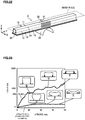
- an analysis model (structure 1) as illustrated in FIG 22 was created, and a simulation simulating pole side collision was carried out.
- the analysis model in FIG 22 has a configuration similar to that of the automotive frame member illustrated in FIG 1 , and is configured by the hat member 10 and the closing plate 20.
- a material of each of the hat member 10 and the closing plate 20 is a steel product having tensile strength of 1180 MPa and a plate thickness of 1.6 mm.
- plural groove formation places 30 are provided at a middle part of the hat member 10 in the member longitudinal direction.
- the entire length of the hat member 10 is 1500 mm, and the height c (the length in the Z direction) of the vertical wall 12 and the width (the length in the X direction) of the top plate 11 are respectively 100 mm.
- the width a and the depth b of the groove part 31 are respectively 20 mm. Specifically, the value of a/c and the value of b/c described above are respectively 0.2.
- the interval between the groove parts is 20 mm.
- the simulation is carried out in a manner that a column-shaped impactor 50 with a radius of 127 mm is pressed against the closing plate 20, and the impactor 50 is displaced at a speed of 1.8 km/h.
- a rigid wall is disposed on the top plate 11.
- an analysis model with a hat member provided with no groove part (structure 2) was created, and a simulation under conditions similar to the above-described conditions was carried out.
- FIG 23 is a load-stroke diagram in the simulation (1).
- a direction of arrow mark in FIG 23 is an input direction.
- the load in the structure 1 is larger than that in the structure 2 having no groove part, and thus the energy absorption performance in the structure 1 is improved.
- a simulation was carried out with an analysis model in which a rigid wall was disposed under the closing plate 20, and the impactor 50 was pressed against the top plate 11 of the hat member 10, as illustrated in FIG 24 . Note that the other simulation conditions are similar to those of the simulation (1).
- FIG 25 is a load-stroke diagram in the simulation (2).
- a direction of arrow mark in FIG 25 is an input direction.
- the load in the structure 1 is larger than that in the structure 2 having no groove part, and thus the energy absorption performance in the structure 1 is improved.
- the effect of improving the energy absorption performance can be achieved even if the top plate 11 is disposed on the vehicle-exterior side or on the vehicle-interior side.
- a relation among a/c, b/c, and the energy absorption efficiency in the simulation (3) is summarized as in FIG. 26 .
- a "preferred range" illustrated in FIG. 26 is a range in which the energy absorption efficiency (absorbed energy / mass) becomes 5.0 [kN ⁇ mm/kg] or more.
- the energy absorption efficiency became high in particular.
- the deformation in the axial crush mode occurred in the automotive frame member.
- FIG. 28 is a view illustrating a relation between e/c and the energy absorption efficiency in the simulation (4).
- the energy absorption efficiency was dramatically improved when compared to a case where the e/c was less than 0.8.
- the deformation in the axial crush mode occurred in the automotive frame member when the e/c was 0.8 and when the e/c was 1.0.
- the length e of the groove part is the length of 80% or more of the height c of the vertical wall, the deformation in the axial crush mode is likely to occur, which enables to effectively improve the energy absorption efficiency.
- FIG. 29 is a view illustrating a relation between the interval d between the groove parts and the energy absorption efficiency in the simulation (5). As illustrated in FIG 29 , under the condition of the present simulation, when the interval d between the groove parts was 50 mm or less, the deformation in the axial crush mode occurred, resulting in that the energy absorption efficiency was improved.
- a material of each of the first hat member and the second hat member is a steel product having tensile strength of 1180 MPa.
- Each of the first hat member and the second hat member is provided with the groove part, as illustrated in FIG 16 .
- a ratio between a height c 2 of the second hat member and a height c 1 of the first hat member (c 2 /c 1 ) is 0.25.
- a shape of the groove part is similar between the first hat member and the second hat member, except for the difference in heights of the hat members.
- the other simulation conditions are similar to those of the simulation (1).
- the simulation is carried out in plural analysis models with different width a of the groove part and depth b of the groove part.
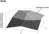
- a relation among a/c, b/c, and the energy absorption efficiency in the simulation (6) is summarized as in FIG. 30 .
- "c” is the sum of the height ci of the first hat member and the height c 2 of the second hat member.
- a "preferred range” illustrated in FIG. 30 is a range in which the energy absorption efficiency becomes 5.0 [kN ⁇ mm/kg] or more.
- the simulation (3) when the a/c was 0.2 to 0.3 and the b/c was 0.2 to 0.3, the deformation in the axial crush mode occurred in the automotive frame member, and the mass efficiency of the energy absorption performance was improved.
- the deformation mode of the automotive frame member was an in-plane deformation mode, but the energy absorption efficiency was 5.0 [kN ⁇ mm/kg] or more.
- the reason why such a result was obtained is because, when the automotive frame member was deformed, the vertical wall positioned between the groove parts was brought into contact with the adjacent vertical wall, resulting in that the load was increased.
- the technique according to the present disclosure can be used for a side sill, a bumper beam, and so on of an automotive.
Applications Claiming Priority (2)
| Application Number | Priority Date | Filing Date | Title |
|---|---|---|---|
| JP2018199818 | 2018-10-24 | ||
| PCT/JP2019/041527 WO2020085381A1 (fr) | 2018-10-24 | 2019-10-23 | Élément de châssis d'automobile et véhicule électrique |
Publications (2)
| Publication Number | Publication Date |
|---|---|
| EP3851335A1 true EP3851335A1 (fr) | 2021-07-21 |
| EP3851335A4 EP3851335A4 (fr) | 2021-10-27 |
Family
ID=70331125
Family Applications (1)
| Application Number | Title | Priority Date | Filing Date |
|---|---|---|---|
| EP19876878.0A Pending EP3851335A4 (fr) | 2018-10-24 | 2019-10-23 | Élément de châssis d'automobile et véhicule électrique |
Country Status (5)
| Country | Link |
|---|---|
| US (1) | US11208150B2 (fr) |
| EP (1) | EP3851335A4 (fr) |
| JP (1) | JP6703322B1 (fr) |
| CN (1) | CN112867637A (fr) |
| WO (1) | WO2020085381A1 (fr) |
Cited By (1)
| Publication number | Priority date | Publication date | Assignee | Title |
|---|---|---|---|---|
| WO2024019754A1 (fr) * | 2022-07-19 | 2024-01-25 | Shape Corp. | Garniture de bas de caisse avec une pluralité de bosses |
Families Citing this family (1)
| Publication number | Priority date | Publication date | Assignee | Title |
|---|---|---|---|---|
| WO2022025098A1 (fr) * | 2020-07-31 | 2022-02-03 | 日本製鉄株式会社 | Élément de structure pour carrosserie d'automobile |
Family Cites Families (15)
| Publication number | Priority date | Publication date | Assignee | Title |
|---|---|---|---|---|
| DE10309636B4 (de) * | 2003-03-04 | 2012-08-09 | Audi Ag | Karosserieträger mit einer den Verformungsverlauf bei einem Aufprall beeinflussenden Nebenform |
| JP4285410B2 (ja) | 2005-01-26 | 2009-06-24 | 三菱自動車工業株式会社 | 車体補強構造 |
| JP2006207679A (ja) | 2005-01-27 | 2006-08-10 | Honda Motor Co Ltd | 衝撃吸収部材の製造方法 |
| DE102006001061A1 (de) * | 2006-01-07 | 2007-09-06 | GM Global Technology Operations, Inc., Detroit | Kraftfahrzeug mit wenigstens einem längsseitig an seiner Karosserie verlaufenden, verstärkten Türschweller |
| JP4330652B2 (ja) * | 2007-03-28 | 2009-09-16 | ユニプレス株式会社 | 車両用金属製アブソーバ、車両用バンパシステム、自動車バンパ用アブソーバ及び自動車バンパシステム |
| JP2009227037A (ja) * | 2008-03-21 | 2009-10-08 | Toyota Motor Corp | 車両のバンパ構造及びエネルギ吸収体 |
| JP5549964B2 (ja) * | 2012-06-04 | 2014-07-16 | 新日鐵住金株式会社 | 耐衝突性能に優れた車両用骨格部材構造 |
| DE102014016044A1 (de) * | 2014-10-29 | 2016-05-04 | GM Global Technology Operations LLC (n. d. Ges. d. Staates Delaware) | Frontpartie eines Kraftfahrzeugs und Stoßfängeraussteifung dazu |
| JP6308190B2 (ja) * | 2015-09-14 | 2018-04-11 | トヨタ自動車株式会社 | 車体骨格構造 |
| JP6514248B2 (ja) | 2017-02-17 | 2019-05-15 | 本田技研工業株式会社 | 車体の下部構造 |
| EP3578444A4 (fr) * | 2017-03-10 | 2020-03-04 | Mazda Motor Corporation | Structure inférieure de carrosserie de véhicule pour véhicule |
| KR102297161B1 (ko) * | 2017-04-10 | 2021-09-02 | 닛폰세이테츠 가부시키가이샤 | 자동차용의 구조 부재 및 그 제조 방법 |
| WO2018213306A1 (fr) * | 2017-05-16 | 2018-11-22 | Shape Corp. | Plateau à batterie de véhicule ayant un composant à base de bac |
| US10293862B1 (en) * | 2018-01-12 | 2019-05-21 | Ford Global Technologies, Llc | Side sill assembly reinforced with a tube and box-shaped brackets |
| US10850774B2 (en) * | 2018-11-13 | 2020-12-01 | Dura Operating, Llc | Side rail assembly for a vehicle |
-
2019
- 2019-10-23 EP EP19876878.0A patent/EP3851335A4/fr active Pending
- 2019-10-23 CN CN201980068245.9A patent/CN112867637A/zh active Pending
- 2019-10-23 WO PCT/JP2019/041527 patent/WO2020085381A1/fr unknown
- 2019-10-23 JP JP2020506390A patent/JP6703322B1/ja active Active
- 2019-10-23 US US17/284,995 patent/US11208150B2/en active Active
Cited By (1)
| Publication number | Priority date | Publication date | Assignee | Title |
|---|---|---|---|---|
| WO2024019754A1 (fr) * | 2022-07-19 | 2024-01-25 | Shape Corp. | Garniture de bas de caisse avec une pluralité de bosses |
Also Published As
| Publication number | Publication date |
|---|---|
| US20210245812A1 (en) | 2021-08-12 |
| EP3851335A4 (fr) | 2021-10-27 |
| JP6703322B1 (ja) | 2020-06-03 |
| CN112867637A (zh) | 2021-05-28 |
| US11208150B2 (en) | 2021-12-28 |
| WO2020085381A1 (fr) | 2020-04-30 |
| JPWO2020085381A1 (ja) | 2021-02-15 |
Similar Documents
| Publication | Publication Date | Title |
|---|---|---|
| CN102414049B (zh) | 保险杠结构 | |
| JP5549964B2 (ja) | 耐衝突性能に優れた車両用骨格部材構造 | |
| EP2823928A1 (fr) | Structure de couplage | |
| US11414032B2 (en) | Closed cross-sectional structure member having high collision performance and automobile body structure | |
| US11208150B2 (en) | Automotive frame member and electric vehicle | |
| JP2006335241A (ja) | バンパステイおよびバンパ装置 | |
| JP6681912B2 (ja) | 自動車のロッカ及びそのようなロッカを備える自動車 | |
| CN106184384B (zh) | 车身增强结构 | |
| JP6973517B2 (ja) | 車両用構造部材 | |
| JP7264597B2 (ja) | 車両用構造部材及び車両 | |
| US20240097256A1 (en) | Battery case of automobile and method for manufacturing the same | |
| KR101359164B1 (ko) | 자동차용 범퍼빔 | |
| JP7376797B2 (ja) | 自動車骨格部材および電気自動車 | |
| JP6687179B1 (ja) | 自動車骨格部材および電気自動車 | |
| US11981370B2 (en) | Structural member for vehicle | |
| US20220177034A1 (en) | Structural member for vehicle | |
| WO2020085383A1 (fr) | Élément de châssis d'automobile et automobile électrique | |
| JP6340896B2 (ja) | センターピラー用鋼部材 | |
| EP4230508A1 (fr) | Structure inférieure de carrosserie de véhicule d'une automobile | |
| EP3604086B1 (fr) | Élément d'absorption de chocs et élément latéral d'automobile | |
| CN218021831U (zh) | 一种纵梁总成及车辆 | |
| JP2021054399A (ja) | 車両用構造部材 | |
| JP2015199405A (ja) | 車両用フレーム構造 | |
| JP2020175752A (ja) | 車体前部構造 | |
| JP2009241724A (ja) | 車両用バンパビーム |
Legal Events
| Date | Code | Title | Description |
|---|---|---|---|
| STAA | Information on the status of an ep patent application or granted ep patent |
Free format text: STATUS: THE INTERNATIONAL PUBLICATION HAS BEEN MADE |
|
| PUAI | Public reference made under article 153(3) epc to a published international application that has entered the european phase |
Free format text: ORIGINAL CODE: 0009012 |
|
| STAA | Information on the status of an ep patent application or granted ep patent |
Free format text: STATUS: REQUEST FOR EXAMINATION WAS MADE |
|
| 17P | Request for examination filed |
Effective date: 20210415 |
|
| AK | Designated contracting states |
Kind code of ref document: A1 Designated state(s): AL AT BE BG CH CY CZ DE DK EE ES FI FR GB GR HR HU IE IS IT LI LT LU LV MC MK MT NL NO PL PT RO RS SE SI SK SM TR |
|
| A4 | Supplementary search report drawn up and despatched |
Effective date: 20210929 |
|
| RIC1 | Information provided on ipc code assigned before grant |
Ipc: B62D 29/00 20060101ALN20210923BHEP Ipc: B62D 25/02 20060101ALI20210923BHEP Ipc: B62D 21/15 20060101ALI20210923BHEP Ipc: B60R 19/18 20060101AFI20210923BHEP |
|
| DAV | Request for validation of the european patent (deleted) | ||
| DAX | Request for extension of the european patent (deleted) | ||
| STAA | Information on the status of an ep patent application or granted ep patent |
Free format text: STATUS: EXAMINATION IS IN PROGRESS |
|
| 17Q | First examination report despatched |
Effective date: 20230912 |