EP3845743A1 - Ventiltrieb und motor - Google Patents
Ventiltrieb und motor Download PDFInfo
- Publication number
- EP3845743A1 EP3845743A1 EP20216680.7A EP20216680A EP3845743A1 EP 3845743 A1 EP3845743 A1 EP 3845743A1 EP 20216680 A EP20216680 A EP 20216680A EP 3845743 A1 EP3845743 A1 EP 3845743A1
- Authority
- EP
- European Patent Office
- Prior art keywords
- support
- oil path
- rocker shaft
- concave portion
- valve gear
- Prior art date
- Legal status (The legal status is an assumption and is not a legal conclusion. Google has not performed a legal analysis and makes no representation as to the accuracy of the status listed.)
- Granted
Links
Images






Classifications
-
- F—MECHANICAL ENGINEERING; LIGHTING; HEATING; WEAPONS; BLASTING
- F01—MACHINES OR ENGINES IN GENERAL; ENGINE PLANTS IN GENERAL; STEAM ENGINES
- F01M—LUBRICATING OF MACHINES OR ENGINES IN GENERAL; LUBRICATING INTERNAL COMBUSTION ENGINES; CRANKCASE VENTILATING
- F01M9/00—Lubrication means having pertinent characteristics not provided for in, or of interest apart from, groups F01M1/00 - F01M7/00
- F01M9/10—Lubrication of valve gear or auxiliaries
- F01M9/105—Lubrication of valve gear or auxiliaries using distribution conduits
-
- F—MECHANICAL ENGINEERING; LIGHTING; HEATING; WEAPONS; BLASTING
- F01—MACHINES OR ENGINES IN GENERAL; ENGINE PLANTS IN GENERAL; STEAM ENGINES
- F01L—CYCLICALLY OPERATING VALVES FOR MACHINES OR ENGINES
- F01L1/00—Valve-gear or valve arrangements, e.g. lift-valve gear
- F01L1/26—Valve-gear or valve arrangements, e.g. lift-valve gear characterised by the provision of two or more valves operated simultaneously by same transmitting-gear; peculiar to machines or engines with more than two lift-valves per cylinder
-
- F—MECHANICAL ENGINEERING; LIGHTING; HEATING; WEAPONS; BLASTING
- F01—MACHINES OR ENGINES IN GENERAL; ENGINE PLANTS IN GENERAL; STEAM ENGINES
- F01L—CYCLICALLY OPERATING VALVES FOR MACHINES OR ENGINES
- F01L1/00—Valve-gear or valve arrangements, e.g. lift-valve gear
- F01L1/02—Valve drive
- F01L1/04—Valve drive by means of cams, camshafts, cam discs, eccentrics or the like
- F01L1/047—Camshafts
- F01L1/053—Camshafts overhead type
-
- F—MECHANICAL ENGINEERING; LIGHTING; HEATING; WEAPONS; BLASTING
- F01—MACHINES OR ENGINES IN GENERAL; ENGINE PLANTS IN GENERAL; STEAM ENGINES
- F01L—CYCLICALLY OPERATING VALVES FOR MACHINES OR ENGINES
- F01L1/00—Valve-gear or valve arrangements, e.g. lift-valve gear
- F01L1/12—Transmitting gear between valve drive and valve
- F01L1/18—Rocking arms or levers
-
- F—MECHANICAL ENGINEERING; LIGHTING; HEATING; WEAPONS; BLASTING
- F01—MACHINES OR ENGINES IN GENERAL; ENGINE PLANTS IN GENERAL; STEAM ENGINES
- F01L—CYCLICALLY OPERATING VALVES FOR MACHINES OR ENGINES
- F01L1/00—Valve-gear or valve arrangements, e.g. lift-valve gear
- F01L1/12—Transmitting gear between valve drive and valve
- F01L1/18—Rocking arms or levers
- F01L1/181—Centre pivot rocking arms
-
- F—MECHANICAL ENGINEERING; LIGHTING; HEATING; WEAPONS; BLASTING
- F01—MACHINES OR ENGINES IN GENERAL; ENGINE PLANTS IN GENERAL; STEAM ENGINES
- F01L—CYCLICALLY OPERATING VALVES FOR MACHINES OR ENGINES
- F01L1/00—Valve-gear or valve arrangements, e.g. lift-valve gear
- F01L1/02—Valve drive
- F01L1/04—Valve drive by means of cams, camshafts, cam discs, eccentrics or the like
- F01L1/047—Camshafts
- F01L1/053—Camshafts overhead type
- F01L2001/0537—Double overhead camshafts [DOHC]
-
- F—MECHANICAL ENGINEERING; LIGHTING; HEATING; WEAPONS; BLASTING
- F01—MACHINES OR ENGINES IN GENERAL; ENGINE PLANTS IN GENERAL; STEAM ENGINES
- F01L—CYCLICALLY OPERATING VALVES FOR MACHINES OR ENGINES
- F01L1/00—Valve-gear or valve arrangements, e.g. lift-valve gear
- F01L1/12—Transmitting gear between valve drive and valve
- F01L1/18—Rocking arms or levers
- F01L2001/186—Split rocking arms, e.g. rocker arms having two articulated parts and means for varying the relative position of these parts or for selectively connecting the parts to move in unison
-
- F—MECHANICAL ENGINEERING; LIGHTING; HEATING; WEAPONS; BLASTING
- F01—MACHINES OR ENGINES IN GENERAL; ENGINE PLANTS IN GENERAL; STEAM ENGINES
- F01L—CYCLICALLY OPERATING VALVES FOR MACHINES OR ENGINES
- F01L2810/00—Arrangements solving specific problems in relation with valve gears
- F01L2810/02—Lubrication
Definitions
- the present invention relates to valve gears and engines, and more specifically to a valve gear and an engine, which are able to change a lift amount, an opening timing, and a closing timing of a valve.
- JP-A 2009-91971 discloses an example pertinent to conventional techniques of this kind.
- JP-A 2009-91971 discloses a variable valve mechanism which includes a rocker arm provided with a switching mechanism for hydraulically changing a valve opening amount, and two rocker arm support members provided at a widthwise distance of the rocker arm for supporting the rocker arm.
- each rocker arm support member has a fitting portion for fitting into an attaching hole formed in a cylinder head, a protruding portion protruding from the cylinder head, and a support portion formed in the protruding portion.
- rocker shaft Two end portions of a rocker shaft (a pivot pin) are pressed into through-holes at support portions of the two rocker arm support members, so that the rocker arm is supported pivotably via the rocker shaft.
- the rocker arm has an input member which abuts on a rotating cam, and an output member which abuts on the valve. Also, in order to transmit hydraulic pressure which is supplied from outside to the switching mechanism, an oil path is formed which comes from outside through one of the rocker arm support members, through the rocker shaft, through the rocker arm, to a hydraulic chamber in the switching mechanism.
- the switching mechanism hydraulically switches between a connected state in which the input member and the output member are mutually connected so that they are unable to move relatively from each other, and a non-connected state in which the connection is not established, and this switching changes the valve opening amount.
- JP-A 2009-91971 discloses an arrangement for transmitting hydraulic pressure to the switching mechanism to perform connection-switching as described above, it discloses nothing about means for lubricating regions of sliding movement between the rocker arm and the rotating cam, and therefore, no description is provided about means for stabilizing hydraulic pressure of the connection-switching or hydraulic pressure of the lubrication.
- valve gears and engines that are each able to stably supply hydraulic pressure to switch the connection of the rocker arm and hydraulic pressure to lubricate between the rocker arm and the cam.
- a valve gear for a cylinder head including a first oil path and a second oil path includes a rocker shaft; a first support that supports a first end region of the rocker shaft; a second support that supports a second end region of the rocker shaft; a rocker arm including a first arm portion supported pivotably by the rocker shaft and pivoted by a cam, and a second arm portion supported pivotably by the rocker shaft to drive a valve; a switch provided in the rocker arm to hydraulically connect and disconnect the first arm portion and the second arm portion to/from each other; a third oil path extending through the first support, the rocker shaft, and the rocker arm to the switch to supply a hydraulic pressure to the switch; and a fourth oil path extending through the second support and the rocker shaft to a region between the rocker shaft and the rocker arm to lubricate areas between the cam and the rocker arm.
- the first support includes, on its outer surface, a first concave portion located at an inlet of the third oil path and to connect to the first oil path, and a second concave portion to connect to the second oil path; and the second support includes, on its outer surface, a third concave portion to connect to the first oil path, and a fourth concave portion located at an inlet of the fourth oil path and to connect to the second oil path.
- the first oil path crosses the first support and the second support and the second oil path crosses the first support and the second support when the first support and the second support are installed to the cylinder head; and the first oil path communicates with the third oil path while the second oil path communicates with the fourth oil path; then, the first oil path and the second oil path would have a decreased cross-sectional area where they cross the first support or the second support.
- the first support includes on its outer surface the first concave portion connected to the first oil path such that it becomes possible to reduce a decrease in a cross-sectional area in the first oil path where the junction is made with the first support, and the second concave portion connected to the second oil path such that it becomes possible to reduce a decrease in a cross-sectional area in the second oil path where the junction is made with the first support.
- the second support includes on its outer surface the third concave portion connected to the first oil path such that it becomes possible to reduce a decrease in a cross-sectional area in the first oil path where the junction is made with the second support, and the fourth concave portion connected to the second oil path such that it becomes possible to reduce a decrease in a cross-sectional area in the second oil path where the junction is made with the second support. Therefore, it is possible to reduce a delayed response in the connection-switching hydraulic pressure in the rocker arm, and in the lubrication hydraulic pressure between the rocker arm and the cam, and to supply a stable hydraulic pressure.
- each of the first concave portion and the second concave portion includes a first constriction and a second constriction extending entirely around the outer circumference of the first support
- each of the third concave portion and the fourth concave portion includes a third constriction and a fourth constriction extending entirely around the outer circumference of the second support.
- the first support and the second support have an identical or substantially identical outer surface shape.
- the valve gear further includes a first regulator to connect the first support with the rocker shaft to regulate movement in a rotational direction and an axial direction of the rocker shaft.
- a first regulator to connect the first support with the rocker shaft to regulate movement in a rotational direction and an axial direction of the rocker shaft.
- the first regulator includes a press-fit pin.
- the first regulator is a small member, i.e., the press-fit pin, a high level of freedom is provided in the layout making it possible to fix the rocker shaft and the first support reliably with each other.
- valve gear further includes a second regulator to connect the second support with the rocker shaft to regulate movement of the rocker shaft in directions perpendicular or substantially perpendicular to the axial direction.
- a second regulator to connect the second support with the rocker shaft to regulate movement of the rocker shaft in directions perpendicular or substantially perpendicular to the axial direction.
- the valve gear further includes a retainer provided on an outer side of the second regulator in the rocker shaft to prevent the second support from detaching from the rocker shaft.
- a retainer provided on an outer side of the second regulator in the rocker shaft to prevent the second support from detaching from the rocker shaft.
- the retainer includes a circlip.
- the circlip adequately prevents separation yet is easy to attach/detach, this structural arrangement makes it easy to perform repair work for the rocker arm, and reduce costs.
- an engine includes a cylinder head including a first insertion hole and a second insertion hole, and the above-described valve gear including the first support and the second support inserted into the first insertion hole and the second insertion hole, respectively.
- the first oil path and the third oil path communicate with each other via the first concave portion
- the second concave portion is connected to the second oil path
- the third concave portion is connected to the first oil path
- the second oil path and the fourth oil path communicate with each other via the fourth concave portion.
- the valve gear is installed on the cylinder head by inserting the first support and the second support into the first insertion hole and the second insertion hole, respectively. Then, the first concave portion and second concave portion of the first support are connected to the first oil path and the second oil path, respectively, while the third concave portion and fourth concave portion of the second support are connected to the first oil path and the second oil path, respectively.
- the second support is located farther downstream in the second oil path than the first support.
- the second support is located farther downstream in the second oil path than the first support; and both of the first support and the second support cross with the second oil path; then the second oil path has a reduced cross-sectional area at a location where it crosses the first support.
- the cylinder head includes a plurality of cylinders located axially along the rocker shaft, the first insertion hole and the second insertion hole are provided for each cylinder and located axially along the rocker shaft, the valve gear is provided for each cylinder, and each of the first oil path and the second oil path extends axially along the rocker shaft and is shared by the plurality of valve gears.
- preferred embodiments of the present invention are suitable for a multi-cylinder engine which includes a plurality of cylinders disposed in-line.
- an engine 10 according to a preferred embodiment of the present invention is installed in an automobile 1 and is used as a propelling source of the automobile 1.
- the engine 10 is a multi-cylinder engine which includes a plurality of cylinders and, in the present preferred embodiment, is a straight four-cylinder engine.
- the engine 10 includes a crank case 12 which houses a crank shaft (not illustrated), a cylinder block 14 connected with the crank case 12, a cylinder head 16 connected with the cylinder block 14, and a cylinder head cover 18 attached to the cylinder head 16.
- the cylinder block 14 includes a plurality of cylinders located axially along a rocker shaft 56 (which will be described below).
- a combustion chamber 22 is provided in the cylinder block 14 and the cylinder head 16.
- the cylinder head 16 includes an intake port 20a and an exhaust port 20b.
- the intake port 20a communicates with the combustion chamber 22 via two air inlets 24a, while the exhaust port 20b communicates with the combustion chamber 22 via two exhaust outlets 24b.
- the cylinder head 16 is provided with two intake valves 26a and two exhaust valves 26b assembled thereto.
- Each intake valve 26a opens/closes a corresponding one of the air inlets 24a of the intake port 20a, while each exhaust valve 26b opens/closes a corresponding one of the exhaust outlets 24b of the exhaust ports 20b.
- the intake valve 26a is slidably supported by the cylinder head 16 via a cylindrical sleeve 28a. At an end of the sleeve 28a, on the intake valve 26a, a valve stem seal 30a is attached. A tappet 32a is fitted to a tip of the intake valve 26a. A valve spring retainer 36a is fixed to the intake valve 26a via a cotter 34a. Between the cylinder head 16 and the valve spring retainer 36a, a valve spring 38a is provided to urge the intake valve 26a with a force (in upward direction in Fig. 3 ) to close the air inlet 24a.
- the valve spring 38a is a compression coil spring.
- the cylinder head 16 rotatably supports an intake cam shaft 40a and an exhaust cam shaft 40b each extending axially along the rocker shaft 56.
- the intake cam shaft 40a is provided, for each cylinder, with an intake cam 42a which makes sliding contact with a first arm portion 96 that will be described below, and two intake cams 44a which make sliding contact with a second arm portion 98 that will be described below.
- the exhaust cam shaft 40b is provided, for each cylinder, with an exhaust cam 42b which makes sliding contact with the first arm portion 96, and two exhaust cams 44b which make sliding contact with the second arm portion 98.
- the cylinder head 16 is provided, for each cylinder, with a valve gear 46 for intake, and a valve gear 46 for exhaust.
- the valve gear 46 for intake receives a force from the intake cam 42a or the intake cam 44a to open/close the intake valve 26a.
- the valve gear 46 for exhaust receives a force from the exhaust cam 42b or the exhaust cam 44b to open/close the exhaust valve 26b.
- the cylinder head 16 is provided, for each valve gear 46 for intake, with a first insertion hole 48a and a second insertion hole 50a to attach the valve gear 46, and for each valve gear 46 for exhaust, with a first insertion hole 48b and a second insertion hole 50b to attach the valve gear 46.
- the first insertion hole 48a and the second insertion hole 50a are provided for each cylinder and located axially along the rocker shaft 56.
- the first insertion hole 48b and the second insertion hole 50b are provided for each cylinder and located axially along the rocker shaft 56.
- the cylinder head 16 is provided, on the side where the valve gears 46 for intake are located, with a first oil path 52a for connection-switching, and a second oil path 54a for lubrication; and on the side where the valve gears 46 for exhaust are located, with a first oil path 52b for connection-switching, and a second oil path 54b for lubrication.
- the first oil paths 52a, 52b and the second oil paths 54a, 54b extend lengthwise of the cylinder head 16, with the upstream side being an upper side in Fig. 2 and the downstream side being a lower side therein.
- Each of the first oil path 52a and the second oil path 54a is shared by the valve gears 46 for intake and extends axially along the rocker shaft 56.
- Each of the first oil path 52b and the second oil path 54b is shared by the valve gears 46 on the exhaust-side and extends axially along the rocker shaft 56. Also, each of the second oil paths 54a, 54b is positioned at a higher location than the first oil paths 52a, 52b.
- valve gears 46 on the intake side are configured the same way and can be easily understood, so that duplicate description thereof will be omitted.
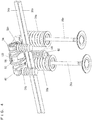
- the valve gear 46 includes the rocker shaft 56.
- the rocker shaft 56 includes a first end region which is supported by a first support 58a.
- the rocker shaft 56 includes a second end region which is supported by the second support 58b.
- the rocker shaft 56 pivotably supports a rocker arm 60 between a first support 58a and the second support 58b.
- the valve gear 46 includes a lost motion mechanism 62 which acts on the rocker arm 60.
- the rocker shaft 56 is bar-shaped or substantially bar-shaped, includes a concave portion 64 to receive a press-fit pin 92 (which will be described below) at a first end region, and an annular groove 66 to receive a circlip 94 (which will be described below) at a second end region.
- the rocker shaft 56 includes, inside thereof, a connection-switching oil path 68 and a lubrication oil path 70.
- the connection-switching oil path 68 which opens at the first end region of the rocker shaft 56
- the lubrication oil path 70 which opens at the second end region of the rocker shaft 56, sandwich a wall portion 71.
- the oil path 70 includes a plurality of (three, in the present preferred embodiment) shower portions 70a penetrating through the rocker shaft 56 and opening in an outer circumferential surface thereof.
- the shower portions 70a are provided axially along the rocker shaft 56 and spaced from each other at positions to oppose cam followers 104, 114a, 114b (which will be described below).
- the oil paths 68, 70 have their respective ends fitted by ball-shaped plug members 72a, 72b, such that the openings of the oil paths 68, 70 are closed.
- the first support 58a includes a substantially pillar-shaped main body 74a and a connecting portion 76a integral therewith at an end portion of the main body 74a.
- the main body 74a includes, on its outer surface, a first constriction 78a provided at an inlet of a third oil path 136 (which will be described below) and to connect to the first oil path 52a; a second constriction 80a to connect to the second oil path 54a; and a groove 82a.
- Each of the first constriction 78a, the second constriction 80a, and the groove 82a extends entirely around an outer surface of the first support 58a, i.e., they are annular-shaped.
- a circlip 84a is attached to the groove 82a to prevent disengagement.
- the connecting portion 76a includes a through-hole 86a which penetrates the first support 58a perpendicular or substantially perpendicular to the longitudinal direction thereof, and a through-hole 88a corresponding to the concave portion 64 of the rocker shaft 56.
- the first support 58a includes a substantially T-shaped oil path 90a which starts from the first constriction 78a and extends to the through-hole 86a of the connecting portion 76a.
- the second support 58b includes a substantially pillar-shaped main body 74b and a connecting portion 76b integral therewith at an end portion of the main body 74b.
- the main body 74b includes, on its outer surface, a third constriction 78b to connect to the first oil path 52a; a fourth constriction 80b provided at an inlet of the fourth oil path 138 (which will be described below) and to connect to the second oil path 54a; and a groove 82b.
- Each of the third constriction 78b, the fourth constriction 80b, and the groove 82b extends entirely around an outer surface of the second support 58b, i.e., they are annular-shaped.
- a circlip 84b is attached to the groove 82b to prevent disengagement.
- the connecting portion 76b includes a through-hole 86b which penetrates the second support 58b perpendicular or substantially perpendicular to the longitudinal direction thereof, and a through-hole 88b similar to the through-hole 88a.
- the second support 58b includes a substantially L-shaped oil path 90b which extends from the fourth constriction 80b to the through-hole 86b of the connecting portion 76b.
- the rocker shaft 56 is fitted with the first support 58a, the rocker arm 60, and the second support 58b in this order.
- the rocker shaft 56 is inserted through the through-hole 86a of the first support 58a, the through-holes 106a, 106b, 116a, 116b (which will be described below) of the rocker arm 60, and the through-hole 86b of the second support 58b.
- the first support 58a is positioned with respect to the rocker shaft 56 so as to align the through-hole 88a with the concave portion 64, and the press-fit pin 92 is pressed into the through-hole 88a and the concave portion 64 such that the first support 58a and the rocker shaft 56 are connected.
- the second support 58b is positioned with respect to the rocker shaft 56, more closely to the first support 58a than the groove 66, and the circlip 94 is fitted around the groove 66.
- the circlip 94 is provided on the outer side of the connecting portion 76b in the rocker shaft 56 in order to prevent the second support 58b from detaching from the rocker shaft 56.
- the rocker arm 60 includes a first arm portion 96 and a second arm portion 98.
- the first arm portion 96 is pivotably supported by the rocker shaft 56 and driven by the intake cam 42a.
- the second arm portion 98 is pivotably supported by the rocker shaft 56 and drivable by the intake cam 44a. Further, the second arm portion 98 pivots, and thus drives the intake valve 26a.
- the first arm portion 96 includes a substantially frame-shaped arm main body 100 (see Fig. 4 through Fig. 8 ), a cylindrical collar 102, a bearing 103, and a cam follower 104.
- the arm main body 100 includes through-holes 106a, 106b and through-holes 108a, 108b.
- the rocker shaft 56 is inserted through the through-holes 106a, 106b such that the arm main body 100 is pivotably supported on the rocker shaft 56.
- the collar 102 is fitted into the through-holes 108a, 108b such that the collar 102 is held at two sides of the arm main body 100.
- the cam follower 104 is rotatable around an outer circumference of the collar 102 via the bearing 103.
- the cam follower 104 makes sliding contact with the intake cam 42a.
- the cam follower 104 faces one of the shower portions 70a of the oil path 70, from which lubricant oil is supplied to the cam follower 104 and the bearing 103
- the second arm portion 98 includes an arm main body 110, cylindrical collars 112a, 112b, bearings 113a, 113b, and cam followers 114a, 114b.
- the arm main body 110 includes through-holes 116a, 116b, a concave portion 118, concave portions 120a, 120b, and communication holes 121a, 121b.
- the concave portions 120a, 120b are provided on both sides of the concave portion 118.
- the rocker shaft 56 is inserted through the through-holes 116a, 116b such that the arm main body 110 is pivotably supported on the rocker shaft 56.
- the first arm portion 96 is located at the concave portion 118.
- the concave portions 120a, 120b are fitted respectively by the collars 112a, 112b.
- the collar 102 of the first arm portion 96 and the collars 112a, 112b of the second arm portion 98 are located axially along the rocker shaft 56, with the collars 112a, 112b sandwiching the collar 102.
- the collars 112a, 112b have their respective outer circumferences provided with the cam followers 114a, 114b rotatably supported by the bearings 113a, 113b.
- the cam followers 114a, 114b make sliding contact with the intake cams 44a, 44a respectively.
- the communication holes 121a, 121b provide communication between respective ones of the shower portions 70a, 70a of the rocker shaft 56 facing the cam followers 114a, 114b and the concave portions 120a, 120b. Therefore, lubrication oil is supplied from the shower portions 70a, 70a of the oil path 70 to the cam followers 114a, 114b and the bearings 113a, 113b via the communication holes 121a, 121b.
- a switch 122 is placed inside of the collar 102 of the first arm portion 96 and the collars 112a, 112b of the second arm portion 98.
- the switch 122 is provided in the rocker arm 60 to hydraulically connect and disconnect the first arm portion 96 and the second arm portion 98 to/from each other.
- the switch 122 includes connecting pins 124, 126, 128, a spring 130, and a lid 132.
- the connecting pins 124, 126, 128, the spring 130, and the lid 132 are coaxial.
- the connecting pins 124, 126, 128 are slidably attached axially along the rocker shaft 56.
- the spring 130 is located between the connecting pin 128 and the lid 132.
- the connecting pin 128 is urged by the spring 130.
- connection-switching oil path 134 is provided inside the second arm portion 98.
- the oil path 134 is located in a region surrounded by the arm main body 110, the collar 112a, and the connecting pin 124.
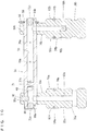
- the valve gear 46 includes a connection-switching third oil path 136 which includes the oil path 90a inside the first support 58a, the oil path 68 inside the rocker shaft 56, and the oil path 134 inside the rocker arm 60 (see Fig. 7 and Fig. 13 ).
- the third oil path 136 extends through the first support 58a, the rocker shaft 56, and the rocker arm 60 to the switch 122.
- the valve gear 46 includes a lubrication fourth oil path 138 which includes the oil path 90b inside the second support 58b, and the oil path 70 inside the rocker shaft 56 (see Fig. 14 ).
- the fourth oil path 138 extends through the second support 58b and the rocker shaft 56 to a region between the rocker shaft 56 and the rocker arm 60.
- the first support 58a, the second support 58b, the rocker shaft 56, and the rocker arm 60 described above are built into an assembly, which is then fixed onto the cylinder head 16 by inserting the first support 58a and the second support 58b into the first insertion hole 48a and the second insertion hole 50a, respectively.
- the first oil path 52a and the third oil path 136 communicate with each other via the first constriction 78a, while the second constriction 80a is connected to the second oil path 54a.
- the third constriction 78b is connected to the first oil path 52a, while the second oil path 54a and the fourth oil path 138 communicate with each other via the fourth constriction 80b.
- the second support 58b is positioned at a more downstream side of the second oil path 54a than the first support 58a.
- the lost motion mechanism 62 includes a lost motion spring 140 to urge the rocker arm 60 toward the intake cam 42a, and is fixed to the cylinder head 16.
- the connecting pins 124, 126, 128 are urged by the spring 130 to slide leftward in Fig. 11 .
- the connecting pins 124, 126, 128 do not connect the first arm portion 96 and the second arm portion 98 with each other.
- the first arm portion 96 and the second arm portion 98 are pivotable independently from each other around the rocker shaft 56 as a fulcrum point.
- the intake cam 42a presses the cam follower 104 in sliding contact therewith, which makes the first arm portion 96 pivot around the rocker shaft 56; independently from this, as the intake cam shaft 40a rotates, the two intake cams 44a press the corresponding cam followers 114a, 114b in sliding contact therewith which makes the second arm portion 98 pivot around the rocker shaft 56. Therefore, without being affected by the action of the first arm portion 96, the second arm portion 98 presses the two intake valves 26a such that the two air inlets 24a of the intake port 20a are opened.
- the intake cam 42a presses the cam follower 104 in sliding contact therewith which makes the first arm portion 96 and the second arm portion 98 pivot integrally with each other around the rocker shaft 56.
- the second arm portion 98 presses the two intake valves 26a such that the two air inlets 24a of the intake port 20a are opened.
- the second arm portion 98 moves the intake valve 26a by a lift amount (an amount the valve is opened), which is determined by a pivot action of the first arm portion 96 that pivots integrally with the second arm portion 98.
- the first constriction 78a, the second constriction 80a, the third constriction 78b, and the fourth constriction 80b correspond to the first concave portion, the second concave portion, the third concave portion, and the fourth concave portion, respectively.
- the press-fit pin 92 corresponds to the first regulator
- the connecting portion 76b corresponds to the second regulator
- the circlip 94 corresponds to the retainer.
- the first support 58a has its outer surface provided with the first constriction 78a as the first concave portion connected to the first oil path 52a (52b) such that it becomes possible to reduce a decrease in a cross-sectional area in the first oil path 52a (52b) where the junction is made with the first support 58a; and is provided with the second constriction 80a as the second concave portion connected to the second oil path 54a (54b) such that it becomes possible to reduce a decrease in a cross-sectional area in the second oil path 54a (54b) where the junction is made with the first support 58a.
- the second support 58b has its outer surface provided with the third constriction 78b as the third concave portion connected to the first oil path 52a (52b) such that it becomes possible to reduce a decrease in a cross-sectional area in the first oil path 52a (52b) where the junction is made with the second support 58b; and provided with the fourth constriction 80b as the fourth concave portion connected to the second oil path 54a (54b) such that it becomes possible to reduce a decrease in a cross-sectional area in the second oil path 54a (54b) where the junction is made with the second support 58b.
- the first support 58a and the second support 58b are inserted respectively through the first insertion hole 48a (48b) and the second insertion hole 50a (50b) such that the cylinder head 16 is provided with the valve gear 46.
- the first constriction 78a and the second constriction 80a as the first concave portion and the second concave portion of the first support 58a are connected to the first oil path 52a (52b) and the second oil path 54a (54b) respectively
- the third constriction 78b and the fourth constriction 80b as the third concave portion and the fourth concave portion of the second support 58b are connected to the first oil path 52a (52b) and the second oil path 54a (54b) respectively.
- the first support 58a and the second support 58b are identical in the shape of their outer surface. This makes it possible to substantially standardize the machining processes of the outer surfaces of the first support 58a and the second support 58b, and therefore makes it possible to reduce costs.
- the first regulator is a small member, i.e., the press-fit pin 92.
- the circlip 94 adequately prevents separation yet it is easy to attach/detach, making it easy to perform repair work for the rocker arm 60 and, in addition, making it possible to provide at a lower cost.
- the first support and the second support may be provided by a first support 142a and a second support 142b shown in Fig. 15 and Fig. 16 .
- the first support 142a in Fig. 15 differs from the first support 58a in Fig. 13 in that it includes a main body 144a in place of the main body 74a.
- the main body 144a differs from the main body 74a in that it includes a first concave portion 146a, a second concave portion 148a, and an oil path 150a in place of the first constriction 78a, the second constriction 80a, and the oil path 90a.
- the first concave portion 146a and the second concave portion 148a preferably have the shape of a hollow half-cylinder.
- the oil path 150a is connected to the first concave portion 146a and is substantially L-shaped. Other arrangements in the first support 142a are the same as the first support 58a.
- the second support 142b in Fig. 16 differs from the second support 58b in Fig. 14 in that it includes a main body 144b in place of the main body 74b.
- the main body 144b differs from the main body 74b in that it includes a third concave portion 146b and a fourth concave portion 148b in place of the third constriction 78b and the fourth constriction 80b.
- the third concave portion 146b and the fourth concave portion 148b preferably have the shape of a hollow half-cylinder.
- Other arrangements in the second support 142b are the same as the second support 58b.
- the first support 142a and the second support 142b described above also provide the same advantages as the first support 58a and the second support 58b.
- first arm portion 96 and the second arm portion 98 change the valve lift amount depending on whether or not the first arm portion 96 and the second arm portion 98 are connected with each other.
- preferred embodiments of the present invention are not limited to this. For example, whether or not the first arm portion 96 and the second arm portion 98 are connected with each other may determine whether or not the valve is brought to an inactive state.
- the engine 10 is a multi-cylinder engine.
- preferred embodiments of the present invention are not limited to this. Preferred embodiments of the present invention may also be applied to a single-cylinder engine.
- the upstream side of the oil path is on the upper side in Fig. 2
- the downstream side of the oil path is on the lower side therein.
- preferred embodiments of the present invention are not limited to this, i.e., the flow may be reversed.
- the engine according to preferred embodiments of the present invention may also be suitably installed in vehicles such as motorcycles, auto-tricycles, and ATVs (All Terrain Vehicles) as well as outboard engines, and others.
- vehicles such as motorcycles, auto-tricycles, and ATVs (All Terrain Vehicles) as well as outboard engines, and others.
- ATVs All Terrain Vehicles
Landscapes
- Engineering & Computer Science (AREA)
- Mechanical Engineering (AREA)
- General Engineering & Computer Science (AREA)
- Valve Device For Special Equipments (AREA)
- Lubrication Of Internal Combustion Engines (AREA)
- Valve-Gear Or Valve Arrangements (AREA)
Applications Claiming Priority (1)
| Application Number | Priority Date | Filing Date | Title |
|---|---|---|---|
| JP2019239843A JP6976308B2 (ja) | 2019-12-27 | 2019-12-27 | 動弁装置およびエンジン |
Publications (2)
| Publication Number | Publication Date |
|---|---|
| EP3845743A1 true EP3845743A1 (de) | 2021-07-07 |
| EP3845743B1 EP3845743B1 (de) | 2023-02-08 |
Family
ID=73856908
Family Applications (1)
| Application Number | Title | Priority Date | Filing Date |
|---|---|---|---|
| EP20216680.7A Active EP3845743B1 (de) | 2019-12-27 | 2020-12-22 | Ventiltrieb und motor |
Country Status (3)
| Country | Link |
|---|---|
| US (1) | US11255236B2 (de) |
| EP (1) | EP3845743B1 (de) |
| JP (1) | JP6976308B2 (de) |
Families Citing this family (2)
| Publication number | Priority date | Publication date | Assignee | Title |
|---|---|---|---|---|
| KR20230173470A (ko) * | 2022-06-17 | 2023-12-27 | 현대자동차주식회사 | 이원화 오일 공급 라인이 적용된 cda 로커 암 시스템 및 그 제어 방법 |
| JP2025088807A (ja) * | 2023-12-01 | 2025-06-12 | スズキ株式会社 | 可変動弁装置 |
Citations (5)
| Publication number | Priority date | Publication date | Assignee | Title |
|---|---|---|---|---|
| DE19526285A1 (de) * | 1995-07-19 | 1997-01-23 | Schaeffler Waelzlager Kg | Vorrichtung zur Schmierstoffversorgung eines Ventiltriebs einer Brennkraftmaschine |
| JP2009091971A (ja) | 2007-10-05 | 2009-04-30 | Otics Corp | ロッカアーム支持部材及び可変動弁機構 |
| DE102015223565A1 (de) * | 2015-11-27 | 2017-06-01 | Schaeffler Technologies AG & Co. KG | Schaltbarer Schlepphebel eines Ventiltriebs |
| EP3418513A1 (de) * | 2017-06-21 | 2018-12-26 | MAN Truck & Bus AG | Kraftübertragungsvorrichtung |
| EP3441583A1 (de) * | 2017-08-10 | 2019-02-13 | Motonic Corporation | Variabler ventilhebeaktuator eines motors |
Family Cites Families (14)
| Publication number | Priority date | Publication date | Assignee | Title |
|---|---|---|---|---|
| JPS63117110A (ja) | 1986-11-01 | 1988-05-21 | Honda Motor Co Ltd | 内燃機関の弁作動特性可変制御装置 |
| JPH04284110A (ja) | 1991-03-08 | 1992-10-08 | Yamaha Motor Co Ltd | スイングアーム式動弁装置 |
| JPH04123313U (ja) | 1991-04-26 | 1992-11-09 | 三菱自動車工業株式会社 | 可変バルブ作動装置 |
| JP4711977B2 (ja) | 2007-01-18 | 2011-06-29 | 株式会社オティックス | 可変動弁機構及びこれに用いられるラッシュアジャスタ |
| JP4931680B2 (ja) | 2007-04-19 | 2012-05-16 | 株式会社オティックス | 動弁機構 |
| US9938865B2 (en) * | 2008-07-22 | 2018-04-10 | Eaton Corporation | Development of a switching roller finger follower for cylinder deactivation in internal combustion engines |
| JP5422181B2 (ja) | 2008-11-25 | 2014-02-19 | ヤマハ発動機株式会社 | 可変動弁装置とこれを備えたエンジン装置および輸送機器 |
| US8939118B2 (en) * | 2011-12-09 | 2015-01-27 | Chrysler Group Llc | Rocker arm providing cylinder deactivation |
| CN104411925B (zh) | 2012-04-20 | 2018-08-31 | 伊顿公司 | 可变气门升程系统、方法和装置 |
| JP6220987B2 (ja) | 2014-10-03 | 2017-10-25 | ヤマハ発動機株式会社 | エンジンの動弁装置 |
| JP6326349B2 (ja) * | 2014-10-21 | 2018-05-16 | 株式会社オティックス | 内燃機関の可変動弁機構 |
| JP2016094901A (ja) | 2014-11-14 | 2016-05-26 | トヨタ自動車株式会社 | 可変動弁装置 |
| US9650922B2 (en) * | 2015-04-28 | 2017-05-16 | Ford Global Technologies, Llc | External oil groove on a hydraulic lash adjuster |
| JP6458090B2 (ja) | 2017-06-30 | 2019-01-23 | ヤマハ発動機株式会社 | 内燃機関および車両 |
-
2019
- 2019-12-27 JP JP2019239843A patent/JP6976308B2/ja active Active
-
2020
- 2020-12-08 US US17/114,559 patent/US11255236B2/en active Active
- 2020-12-22 EP EP20216680.7A patent/EP3845743B1/de active Active
Patent Citations (5)
| Publication number | Priority date | Publication date | Assignee | Title |
|---|---|---|---|---|
| DE19526285A1 (de) * | 1995-07-19 | 1997-01-23 | Schaeffler Waelzlager Kg | Vorrichtung zur Schmierstoffversorgung eines Ventiltriebs einer Brennkraftmaschine |
| JP2009091971A (ja) | 2007-10-05 | 2009-04-30 | Otics Corp | ロッカアーム支持部材及び可変動弁機構 |
| DE102015223565A1 (de) * | 2015-11-27 | 2017-06-01 | Schaeffler Technologies AG & Co. KG | Schaltbarer Schlepphebel eines Ventiltriebs |
| EP3418513A1 (de) * | 2017-06-21 | 2018-12-26 | MAN Truck & Bus AG | Kraftübertragungsvorrichtung |
| EP3441583A1 (de) * | 2017-08-10 | 2019-02-13 | Motonic Corporation | Variabler ventilhebeaktuator eines motors |
Also Published As
| Publication number | Publication date |
|---|---|
| JP2021107705A (ja) | 2021-07-29 |
| EP3845743B1 (de) | 2023-02-08 |
| US11255236B2 (en) | 2022-02-22 |
| JP6976308B2 (ja) | 2021-12-08 |
| US20210199031A1 (en) | 2021-07-01 |
Similar Documents
| Publication | Publication Date | Title |
|---|---|---|
| EP3845743B1 (de) | Ventiltrieb und motor | |
| US5353755A (en) | Arrangement of variable valve timing control system on V-type engine | |
| EP0267696B1 (de) | Ventilantriebsvorrichtung in einer Brennkraftmaschine | |
| US9541184B2 (en) | Mechanical system, injection pump and valve actuator comprising such a mechanical system and manufacturing method | |
| EP1974127B1 (de) | Nockenwellenträgerstruktur eines verbrennungsmotors und montageverfahren dafür | |
| EP2320039B1 (de) | Ölkanäle für motor | |
| US5960754A (en) | Valve operating system in internal combustion engine | |
| US9752670B2 (en) | Mechanical system forming a cam follower or a rocker arm | |
| JP3366196B2 (ja) | 内燃機関の動弁装置 | |
| CN102588026A (zh) | 滚子凸轮从动件 | |
| JPH10317928A (ja) | エンジンの弁作動装置 | |
| EP1462622B1 (de) | Mehrzylinderbrennkraftmaschine | |
| US6895942B2 (en) | Engine fuel pump mounting structure | |
| EP2031197B1 (de) | V-Motor für Fahrzeug | |
| CN201599078U (zh) | 用于内燃发动机的凸轮轴系统 | |
| US10385956B2 (en) | Mechanical system forming a cam follower or a rocker arm | |
| US11193401B2 (en) | Lost motion mechanism, valve gear and engine | |
| US20080022954A1 (en) | Cam follower for a valve drive of an internal combustion engine | |
| US6732693B2 (en) | Valve-operating assembly of driven rotation member and cam | |
| JP2019094870A (ja) | エンジンの潤滑油供給機構 | |
| US5592857A (en) | Variable camshaft phaser | |
| JP3319981B2 (ja) | 内燃機関の動弁装置 | |
| JP6731296B2 (ja) | 潤滑油供給機構 | |
| US20190301318A1 (en) | Oil passageway structure for internal combustion engines | |
| JPS60198317A (ja) | 車両のカム軸潤滑装置 |
Legal Events
| Date | Code | Title | Description |
|---|---|---|---|
| PUAI | Public reference made under article 153(3) epc to a published international application that has entered the european phase |
Free format text: ORIGINAL CODE: 0009012 |
|
| STAA | Information on the status of an ep patent application or granted ep patent |
Free format text: STATUS: THE APPLICATION HAS BEEN PUBLISHED |
|
| AK | Designated contracting states |
Kind code of ref document: A1 Designated state(s): AL AT BE BG CH CY CZ DE DK EE ES FI FR GB GR HR HU IE IS IT LI LT LU LV MC MK MT NL NO PL PT RO RS SE SI SK SM TR |
|
| STAA | Information on the status of an ep patent application or granted ep patent |
Free format text: STATUS: REQUEST FOR EXAMINATION WAS MADE |
|
| 17P | Request for examination filed |
Effective date: 20211116 |
|
| RBV | Designated contracting states (corrected) |
Designated state(s): AL AT BE BG CH CY CZ DE DK EE ES FI FR GB GR HR HU IE IS IT LI LT LU LV MC MK MT NL NO PL PT RO RS SE SI SK SM TR |
|
| GRAP | Despatch of communication of intention to grant a patent |
Free format text: ORIGINAL CODE: EPIDOSNIGR1 |
|
| STAA | Information on the status of an ep patent application or granted ep patent |
Free format text: STATUS: GRANT OF PATENT IS INTENDED |
|
| INTG | Intention to grant announced |
Effective date: 20220712 |
|
| GRAS | Grant fee paid |
Free format text: ORIGINAL CODE: EPIDOSNIGR3 |
|
| GRAA | (expected) grant |
Free format text: ORIGINAL CODE: 0009210 |
|
| STAA | Information on the status of an ep patent application or granted ep patent |
Free format text: STATUS: THE PATENT HAS BEEN GRANTED |
|
| AK | Designated contracting states |
Kind code of ref document: B1 Designated state(s): AL AT BE BG CH CY CZ DE DK EE ES FI FR GB GR HR HU IE IS IT LI LT LU LV MC MK MT NL NO PL PT RO RS SE SI SK SM TR |
|
| REG | Reference to a national code |
Ref country code: GB Ref legal event code: FG4D |
|
| REG | Reference to a national code |
Ref country code: CH Ref legal event code: EP Ref country code: AT Ref legal event code: REF Ref document number: 1547525 Country of ref document: AT Kind code of ref document: T Effective date: 20230215 |
|
| REG | Reference to a national code |
Ref country code: IE Ref legal event code: FG4D |
|
| REG | Reference to a national code |
Ref country code: DE Ref legal event code: R096 Ref document number: 602020007991 Country of ref document: DE |
|
| REG | Reference to a national code |
Ref country code: LT Ref legal event code: MG9D |
|
| REG | Reference to a national code |
Ref country code: NL Ref legal event code: MP Effective date: 20230208 |
|
| REG | Reference to a national code |
Ref country code: AT Ref legal event code: MK05 Ref document number: 1547525 Country of ref document: AT Kind code of ref document: T Effective date: 20230208 |
|
| PG25 | Lapsed in a contracting state [announced via postgrant information from national office to epo] |
Ref country code: RS Free format text: LAPSE BECAUSE OF FAILURE TO SUBMIT A TRANSLATION OF THE DESCRIPTION OR TO PAY THE FEE WITHIN THE PRESCRIBED TIME-LIMIT Effective date: 20230208 Ref country code: PT Free format text: LAPSE BECAUSE OF FAILURE TO SUBMIT A TRANSLATION OF THE DESCRIPTION OR TO PAY THE FEE WITHIN THE PRESCRIBED TIME-LIMIT Effective date: 20230609 Ref country code: NO Free format text: LAPSE BECAUSE OF FAILURE TO SUBMIT A TRANSLATION OF THE DESCRIPTION OR TO PAY THE FEE WITHIN THE PRESCRIBED TIME-LIMIT Effective date: 20230508 Ref country code: NL Free format text: LAPSE BECAUSE OF FAILURE TO SUBMIT A TRANSLATION OF THE DESCRIPTION OR TO PAY THE FEE WITHIN THE PRESCRIBED TIME-LIMIT Effective date: 20230208 Ref country code: LV Free format text: LAPSE BECAUSE OF FAILURE TO SUBMIT A TRANSLATION OF THE DESCRIPTION OR TO PAY THE FEE WITHIN THE PRESCRIBED TIME-LIMIT Effective date: 20230208 Ref country code: LT Free format text: LAPSE BECAUSE OF FAILURE TO SUBMIT A TRANSLATION OF THE DESCRIPTION OR TO PAY THE FEE WITHIN THE PRESCRIBED TIME-LIMIT Effective date: 20230208 Ref country code: HR Free format text: LAPSE BECAUSE OF FAILURE TO SUBMIT A TRANSLATION OF THE DESCRIPTION OR TO PAY THE FEE WITHIN THE PRESCRIBED TIME-LIMIT Effective date: 20230208 Ref country code: ES Free format text: LAPSE BECAUSE OF FAILURE TO SUBMIT A TRANSLATION OF THE DESCRIPTION OR TO PAY THE FEE WITHIN THE PRESCRIBED TIME-LIMIT Effective date: 20230208 Ref country code: AT Free format text: LAPSE BECAUSE OF FAILURE TO SUBMIT A TRANSLATION OF THE DESCRIPTION OR TO PAY THE FEE WITHIN THE PRESCRIBED TIME-LIMIT Effective date: 20230208 |
|
| PG25 | Lapsed in a contracting state [announced via postgrant information from national office to epo] |
Ref country code: SE Free format text: LAPSE BECAUSE OF FAILURE TO SUBMIT A TRANSLATION OF THE DESCRIPTION OR TO PAY THE FEE WITHIN THE PRESCRIBED TIME-LIMIT Effective date: 20230208 Ref country code: PL Free format text: LAPSE BECAUSE OF FAILURE TO SUBMIT A TRANSLATION OF THE DESCRIPTION OR TO PAY THE FEE WITHIN THE PRESCRIBED TIME-LIMIT Effective date: 20230208 Ref country code: IS Free format text: LAPSE BECAUSE OF FAILURE TO SUBMIT A TRANSLATION OF THE DESCRIPTION OR TO PAY THE FEE WITHIN THE PRESCRIBED TIME-LIMIT Effective date: 20230608 Ref country code: GR Free format text: LAPSE BECAUSE OF FAILURE TO SUBMIT A TRANSLATION OF THE DESCRIPTION OR TO PAY THE FEE WITHIN THE PRESCRIBED TIME-LIMIT Effective date: 20230509 Ref country code: FI Free format text: LAPSE BECAUSE OF FAILURE TO SUBMIT A TRANSLATION OF THE DESCRIPTION OR TO PAY THE FEE WITHIN THE PRESCRIBED TIME-LIMIT Effective date: 20230208 |
|
| PG25 | Lapsed in a contracting state [announced via postgrant information from national office to epo] |
Ref country code: SM Free format text: LAPSE BECAUSE OF FAILURE TO SUBMIT A TRANSLATION OF THE DESCRIPTION OR TO PAY THE FEE WITHIN THE PRESCRIBED TIME-LIMIT Effective date: 20230208 Ref country code: RO Free format text: LAPSE BECAUSE OF FAILURE TO SUBMIT A TRANSLATION OF THE DESCRIPTION OR TO PAY THE FEE WITHIN THE PRESCRIBED TIME-LIMIT Effective date: 20230208 Ref country code: EE Free format text: LAPSE BECAUSE OF FAILURE TO SUBMIT A TRANSLATION OF THE DESCRIPTION OR TO PAY THE FEE WITHIN THE PRESCRIBED TIME-LIMIT Effective date: 20230208 Ref country code: DK Free format text: LAPSE BECAUSE OF FAILURE TO SUBMIT A TRANSLATION OF THE DESCRIPTION OR TO PAY THE FEE WITHIN THE PRESCRIBED TIME-LIMIT Effective date: 20230208 Ref country code: CZ Free format text: LAPSE BECAUSE OF FAILURE TO SUBMIT A TRANSLATION OF THE DESCRIPTION OR TO PAY THE FEE WITHIN THE PRESCRIBED TIME-LIMIT Effective date: 20230208 |
|
| REG | Reference to a national code |
Ref country code: DE Ref legal event code: R097 Ref document number: 602020007991 Country of ref document: DE |
|
| PG25 | Lapsed in a contracting state [announced via postgrant information from national office to epo] |
Ref country code: SK Free format text: LAPSE BECAUSE OF FAILURE TO SUBMIT A TRANSLATION OF THE DESCRIPTION OR TO PAY THE FEE WITHIN THE PRESCRIBED TIME-LIMIT Effective date: 20230208 |
|
| PLBE | No opposition filed within time limit |
Free format text: ORIGINAL CODE: 0009261 |
|
| STAA | Information on the status of an ep patent application or granted ep patent |
Free format text: STATUS: NO OPPOSITION FILED WITHIN TIME LIMIT |
|
| 26N | No opposition filed |
Effective date: 20231109 |
|
| PG25 | Lapsed in a contracting state [announced via postgrant information from national office to epo] |
Ref country code: SI Free format text: LAPSE BECAUSE OF FAILURE TO SUBMIT A TRANSLATION OF THE DESCRIPTION OR TO PAY THE FEE WITHIN THE PRESCRIBED TIME-LIMIT Effective date: 20230208 |
|
| REG | Reference to a national code |
Ref country code: CH Ref legal event code: PL |
|
| PG25 | Lapsed in a contracting state [announced via postgrant information from national office to epo] |
Ref country code: LU Free format text: LAPSE BECAUSE OF NON-PAYMENT OF DUE FEES Effective date: 20231222 |
|
| PG25 | Lapsed in a contracting state [announced via postgrant information from national office to epo] |
Ref country code: MC Free format text: LAPSE BECAUSE OF FAILURE TO SUBMIT A TRANSLATION OF THE DESCRIPTION OR TO PAY THE FEE WITHIN THE PRESCRIBED TIME-LIMIT Effective date: 20230208 |
|
| REG | Reference to a national code |
Ref country code: BE Ref legal event code: MM Effective date: 20231231 |
|
| PG25 | Lapsed in a contracting state [announced via postgrant information from national office to epo] |
Ref country code: MC Free format text: LAPSE BECAUSE OF FAILURE TO SUBMIT A TRANSLATION OF THE DESCRIPTION OR TO PAY THE FEE WITHIN THE PRESCRIBED TIME-LIMIT Effective date: 20230208 Ref country code: LU Free format text: LAPSE BECAUSE OF NON-PAYMENT OF DUE FEES Effective date: 20231222 |
|
| REG | Reference to a national code |
Ref country code: IE Ref legal event code: MM4A |
|
| PG25 | Lapsed in a contracting state [announced via postgrant information from national office to epo] |
Ref country code: IE Free format text: LAPSE BECAUSE OF NON-PAYMENT OF DUE FEES Effective date: 20231222 |
|
| PG25 | Lapsed in a contracting state [announced via postgrant information from national office to epo] |
Ref country code: BE Free format text: LAPSE BECAUSE OF NON-PAYMENT OF DUE FEES Effective date: 20231231 |
|
| PG25 | Lapsed in a contracting state [announced via postgrant information from national office to epo] |
Ref country code: CH Free format text: LAPSE BECAUSE OF NON-PAYMENT OF DUE FEES Effective date: 20231231 |
|
| PG25 | Lapsed in a contracting state [announced via postgrant information from national office to epo] |
Ref country code: IE Free format text: LAPSE BECAUSE OF NON-PAYMENT OF DUE FEES Effective date: 20231222 Ref country code: CH Free format text: LAPSE BECAUSE OF NON-PAYMENT OF DUE FEES Effective date: 20231231 Ref country code: BE Free format text: LAPSE BECAUSE OF NON-PAYMENT OF DUE FEES Effective date: 20231231 |
|
| PG25 | Lapsed in a contracting state [announced via postgrant information from national office to epo] |
Ref country code: BG Free format text: LAPSE BECAUSE OF FAILURE TO SUBMIT A TRANSLATION OF THE DESCRIPTION OR TO PAY THE FEE WITHIN THE PRESCRIBED TIME-LIMIT Effective date: 20230208 |
|
| PG25 | Lapsed in a contracting state [announced via postgrant information from national office to epo] |
Ref country code: BG Free format text: LAPSE BECAUSE OF FAILURE TO SUBMIT A TRANSLATION OF THE DESCRIPTION OR TO PAY THE FEE WITHIN THE PRESCRIBED TIME-LIMIT Effective date: 20230208 |
|
| PG25 | Lapsed in a contracting state [announced via postgrant information from national office to epo] |
Ref country code: CY Free format text: LAPSE BECAUSE OF FAILURE TO SUBMIT A TRANSLATION OF THE DESCRIPTION OR TO PAY THE FEE WITHIN THE PRESCRIBED TIME-LIMIT; INVALID AB INITIO Effective date: 20201222 |
|
| PG25 | Lapsed in a contracting state [announced via postgrant information from national office to epo] |
Ref country code: HU Free format text: LAPSE BECAUSE OF FAILURE TO SUBMIT A TRANSLATION OF THE DESCRIPTION OR TO PAY THE FEE WITHIN THE PRESCRIBED TIME-LIMIT; INVALID AB INITIO Effective date: 20201222 |
|
| PG25 | Lapsed in a contracting state [announced via postgrant information from national office to epo] |
Ref country code: TR Free format text: LAPSE BECAUSE OF FAILURE TO SUBMIT A TRANSLATION OF THE DESCRIPTION OR TO PAY THE FEE WITHIN THE PRESCRIBED TIME-LIMIT Effective date: 20230208 |
|
| PGFP | Annual fee paid to national office [announced via postgrant information from national office to epo] |
Ref country code: DE Payment date: 20251211 Year of fee payment: 6 |
|
| PGFP | Annual fee paid to national office [announced via postgrant information from national office to epo] |
Ref country code: GB Payment date: 20251219 Year of fee payment: 6 |
|
| PGFP | Annual fee paid to national office [announced via postgrant information from national office to epo] |
Ref country code: IT Payment date: 20251223 Year of fee payment: 6 |
|
| PGFP | Annual fee paid to national office [announced via postgrant information from national office to epo] |
Ref country code: FR Payment date: 20251229 Year of fee payment: 6 |