EP3843530B1 - Anordnung und verfahren zur verwaltung des entladens einer last einer forstmaschine - Google Patents
Anordnung und verfahren zur verwaltung des entladens einer last einer forstmaschine Download PDFInfo
- Publication number
- EP3843530B1 EP3843530B1 EP19854463.7A EP19854463A EP3843530B1 EP 3843530 B1 EP3843530 B1 EP 3843530B1 EP 19854463 A EP19854463 A EP 19854463A EP 3843530 B1 EP3843530 B1 EP 3843530B1
- Authority
- EP
- European Patent Office
- Prior art keywords
- timber
- location
- load
- pile
- forestry machine
- Prior art date
- Legal status (The legal status is an assumption and is not a legal conclusion. Google has not performed a legal analysis and makes no representation as to the accuracy of the status listed.)
- Active
Links
Images


Classifications
-
- E—FIXED CONSTRUCTIONS
- E02—HYDRAULIC ENGINEERING; FOUNDATIONS; SOIL SHIFTING
- E02F—DREDGING; SOIL-SHIFTING
- E02F9/00—Component parts of dredgers or soil-shifting machines, not restricted to one of the kinds covered by groups E02F3/00 - E02F7/00
- E02F9/26—Indicating devices
- E02F9/264—Sensors and their calibration for indicating the position of the work tool
- E02F9/265—Sensors and their calibration for indicating the position of the work tool with follow-up actions (e.g. control signals sent to actuate the work tool)
-
- A—HUMAN NECESSITIES
- A01—AGRICULTURE; FORESTRY; ANIMAL HUSBANDRY; HUNTING; TRAPPING; FISHING
- A01G—HORTICULTURE; CULTIVATION OF VEGETABLES, FLOWERS, RICE, FRUIT, VINES, HOPS OR SEAWEED; FORESTRY; WATERING
- A01G23/00—Forestry
- A01G23/003—Collecting felled trees
-
- B—PERFORMING OPERATIONS; TRANSPORTING
- B25—HAND TOOLS; PORTABLE POWER-DRIVEN TOOLS; MANIPULATORS
- B25J—MANIPULATORS; CHAMBERS PROVIDED WITH MANIPULATION DEVICES
- B25J9/00—Program-controlled manipulators
- B25J9/16—Program controls
- B25J9/1628—Program controls characterised by the control loop
- B25J9/1633—Program controls characterised by the control loop compliant, force, torque control, e.g. combined with position control
-
- B—PERFORMING OPERATIONS; TRANSPORTING
- B60—VEHICLES IN GENERAL
- B60P—VEHICLES ADAPTED FOR LOAD TRANSPORTATION OR TO TRANSPORT, TO CARRY, OR TO COMPRISE SPECIAL LOADS OR OBJECTS
- B60P1/00—Vehicles predominantly for transporting loads and modified to facilitate loading, consolidating the load, or unloading
- B60P1/54—Vehicles predominantly for transporting loads and modified to facilitate loading, consolidating the load, or unloading using cranes for self-loading or self-unloading
- B60P1/5404—Vehicles predominantly for transporting loads and modified to facilitate loading, consolidating the load, or unloading using cranes for self-loading or self-unloading with a fixed base
- B60P1/5423—Vehicles predominantly for transporting loads and modified to facilitate loading, consolidating the load, or unloading using cranes for self-loading or self-unloading with a fixed base attached to the loading platform or similar
- B60P1/5433—Vehicles predominantly for transporting loads and modified to facilitate loading, consolidating the load, or unloading using cranes for self-loading or self-unloading with a fixed base attached to the loading platform or similar and having the first pivot on a vertical axis
-
- B—PERFORMING OPERATIONS; TRANSPORTING
- B60—VEHICLES IN GENERAL
- B60P—VEHICLES ADAPTED FOR LOAD TRANSPORTATION OR TO TRANSPORT, TO CARRY, OR TO COMPRISE SPECIAL LOADS OR OBJECTS
- B60P3/00—Vehicles adapted to transport, to carry or to comprise special loads or objects
- B60P3/40—Vehicles adapted to transport, to carry or to comprise special loads or objects for carrying long loads, e.g. with separate wheeled load supporting elements
- B60P3/41—Vehicles adapted to transport, to carry or to comprise special loads or objects for carrying long loads, e.g. with separate wheeled load supporting elements for log transport
-
- B—PERFORMING OPERATIONS; TRANSPORTING
- B66—HOISTING; LIFTING; HAULING
- B66C—CRANES; LOAD-ENGAGING ELEMENTS OR DEVICES FOR CRANES, CAPSTANS, WINCHES, OR TACKLES
- B66C13/00—Other constructional features or details
- B66C13/04—Auxiliary devices for controlling movements of suspended loads, or preventing cable slack
- B66C13/08—Auxiliary devices for controlling movements of suspended loads, or preventing cable slack for depositing loads in desired attitudes or positions
- B66C13/085—Auxiliary devices for controlling movements of suspended loads, or preventing cable slack for depositing loads in desired attitudes or positions electrical
-
- B—PERFORMING OPERATIONS; TRANSPORTING
- B66—HOISTING; LIFTING; HAULING
- B66C—CRANES; LOAD-ENGAGING ELEMENTS OR DEVICES FOR CRANES, CAPSTANS, WINCHES, OR TACKLES
- B66C23/00—Cranes comprising essentially a beam, boom, or triangular structure acting as a cantilever and mounted for translatory of swinging movements in vertical or horizontal planes or a combination of such movements, e.g. jib-cranes, derricks, tower cranes
- B66C23/18—Cranes comprising essentially a beam, boom, or triangular structure acting as a cantilever and mounted for translatory of swinging movements in vertical or horizontal planes or a combination of such movements, e.g. jib-cranes, derricks, tower cranes specially adapted for use in particular purposes
- B66C23/36—Cranes comprising essentially a beam, boom, or triangular structure acting as a cantilever and mounted for translatory of swinging movements in vertical or horizontal planes or a combination of such movements, e.g. jib-cranes, derricks, tower cranes specially adapted for use in particular purposes mounted on road or rail vehicles; Manually-movable jib-cranes for use in workshops; Floating cranes
- B66C23/42—Cranes comprising essentially a beam, boom, or triangular structure acting as a cantilever and mounted for translatory of swinging movements in vertical or horizontal planes or a combination of such movements, e.g. jib-cranes, derricks, tower cranes specially adapted for use in particular purposes mounted on road or rail vehicles; Manually-movable jib-cranes for use in workshops; Floating cranes with jibs of adjustable configuration, e.g. foldable
-
- B—PERFORMING OPERATIONS; TRANSPORTING
- B66—HOISTING; LIFTING; HAULING
- B66C—CRANES; LOAD-ENGAGING ELEMENTS OR DEVICES FOR CRANES, CAPSTANS, WINCHES, OR TACKLES
- B66C23/00—Cranes comprising essentially a beam, boom, or triangular structure acting as a cantilever and mounted for translatory of swinging movements in vertical or horizontal planes or a combination of such movements, e.g. jib-cranes, derricks, tower cranes
- B66C23/54—Cranes comprising essentially a beam, boom, or triangular structure acting as a cantilever and mounted for translatory of swinging movements in vertical or horizontal planes or a combination of such movements, e.g. jib-cranes, derricks, tower cranes with pneumatic or hydraulic motors, e.g. for actuating jib-cranes on tractors
-
- E—FIXED CONSTRUCTIONS
- E02—HYDRAULIC ENGINEERING; FOUNDATIONS; SOIL SHIFTING
- E02F—DREDGING; SOIL-SHIFTING
- E02F3/00—Dredgers; Soil-shifting machines
- E02F3/04—Dredgers; Soil-shifting machines mechanically-driven
- E02F3/28—Dredgers; Soil-shifting machines mechanically-driven with digging tools mounted on a dipper- or bucket-arm, i.e. there is either one arm or a pair of arms, e.g. dippers, buckets
- E02F3/36—Component parts
- E02F3/42—Drives for dippers, buckets, dipper-arms or bucket-arms
- E02F3/43—Control of dipper or bucket position; Control of sequence of drive operations
- E02F3/431—Control of dipper or bucket position; Control of sequence of drive operations for bucket-arms, front-end loaders, dumpers or the like
- E02F3/434—Control of dipper or bucket position; Control of sequence of drive operations for bucket-arms, front-end loaders, dumpers or the like providing automatic sequences of movements, e.g. automatic dumping or loading, automatic return-to-dig
-
- E—FIXED CONSTRUCTIONS
- E02—HYDRAULIC ENGINEERING; FOUNDATIONS; SOIL SHIFTING
- E02F—DREDGING; SOIL-SHIFTING
- E02F3/00—Dredgers; Soil-shifting machines
- E02F3/04—Dredgers; Soil-shifting machines mechanically-driven
- E02F3/28—Dredgers; Soil-shifting machines mechanically-driven with digging tools mounted on a dipper- or bucket-arm, i.e. there is either one arm or a pair of arms, e.g. dippers, buckets
- E02F3/36—Component parts
- E02F3/42—Drives for dippers, buckets, dipper-arms or bucket-arms
- E02F3/43—Control of dipper or bucket position; Control of sequence of drive operations
- E02F3/435—Control of dipper or bucket position; Control of sequence of drive operations for dipper-arms, backhoes or the like
-
- B—PERFORMING OPERATIONS; TRANSPORTING
- B66—HOISTING; LIFTING; HAULING
- B66C—CRANES; LOAD-ENGAGING ELEMENTS OR DEVICES FOR CRANES, CAPSTANS, WINCHES, OR TACKLES
- B66C1/00—Load-engaging elements or devices attached to lifting or lowering gear of cranes or adapted for connection therewith for transmitting lifting forces to articles or groups of articles
- B66C1/10—Load-engaging elements or devices attached to lifting or lowering gear of cranes or adapted for connection therewith for transmitting lifting forces to articles or groups of articles by mechanical means
- B66C1/42—Gripping members engaging only the external or internal surfaces of the articles
- B66C1/58—Gripping members engaging only the external or internal surfaces of the articles and deforming the articles, e.g. by using gripping members such as tongs or grapples
- B66C1/585—Log grapples
Definitions
- This invention relates to off-road work machines and to unloading an off-road work machine and particularly to an arrangement and a method for controlling the unloading of a forestry machine.
- Forestry machines are used in mechanised harvesting for felling, delimbing, cutting to size, collecting, transporting and stacking trees.
- Forestry machines include e.g. harvesters, forwarders and their combinations, the so-called combined machines.
- Harvesters are used in mechanised harvesting for felling, delimbing and cutting trees to size.
- timber is typically stacked in suitable work piles by timber assortment in the felling area.
- forwarders timber is typically collected from the work piles, transported to the side of a road and unloaded into timber piles.
- Combined machines can handle the operations of both, i.e. harvesters and forwarders.
- Forestry machines such as forwarders and combined machines, are off-road work machines which collect timber from various work piles or stacks to be transported to the side of a road to be unloaded into various timber piles.
- the timber piles On the side of the road, the timber piles should be neat and the ends of said timber piles should be even.
- the evenness of the ends of timber piles is a safety issue and also aesthetically desirable.
- a traditionally used manner of controlling the unloading of a forestry machine operates such that a driver of the forestry machine controls the unloading of a timber load into a timber pile by manual controls.
- the driver of the forestry machine should be particularly attentive for making the end of the timber pile even.
- International specification WO2018/130747A1 describes a prior-art arrangement for controlling the unloading of a forestry machine.
- European specification EP2987399A1 also describes another prior-art arrangement for controlling the unloading of a forestry machine.
- Finnish specification FI20145397A describes a prior-art arrangement for controlling the boom structure of a forwarder.
- Finnish utility model FI7189U describes a prior-art arrangement for controlling a timber feeder.
- KHT Doctoral Thesis by Björn Löfgren "Kinematic Control of Redundant Knuckle Booms with Automatic Path-Following Functions" describes a Kinematic Simulator Software (KSS) and a Dynamic Forest Machine Simulator (DFMS), which simulator arrangements are then further studied and analyzed.
- KSS Kinematic Simulator Software
- DFMS Dynamic Forest Machine Simulator
- the even unloading of a timber load into a timber pile by means of the manual control according to prior art has thus proved extremely time-consuming and awkward.
- the purpose of this invention is to provide a novel kind of an arrangement for controlling the unloading of a forestry machine, by means of which, it is possible to achieve a more controllable, time-saving and reliable arrangement in unloading timber loads into timber piles than the previous arrangements e.g. on the side of a road and, by means of which, problems and disadvantages in unloading timber loads can be minimised.
- the forestry machine comprises a load space for a timber load, a boom structure and a wood-handling tool attached to said boom structure, which arrangement further comprises a control system and a measuring apparatus of the forestry machine in which said measuring apparatus is arranged to measure the location of the forestry machine and the rotation angle of the boom structure and the position of the single boom parts of the boom structure and the position of the wood-handling tool; and in which: said control system is arranged: to define and note down the location of a timber pile, to calculate and note down the location of an edge of the timber pile, to control the wood-handling tool to pick a timber bundle from the timber load, to calculate the distance of an end justified to a load screen of said timber bundle from the wood-handling tool, to calculate an unloading location for said timber bundle into a timber pile even and straight of its one edge in the defined timber pile location, and to control and unload said timber bundle in said calculated unloading location in the timber
- said measuring apparatus is arranged to measure the motion space of single boom parts of the boom structure.
- said measuring apparatus is arranged to measure the rotation angle of the wood-handling tool.
- said control system is arranged to control the rotation angle of said boom structure and the position of single boom parts of the boom structure and the location of said wood-handling tool.
- said measuring apparatus is arranged to measure the position of grabbing means of the wood-handling tool.
- said control system is arranged to identify and/or control the position of the grabbing means of the wood-handling tool.
- said control system is arranged to calculate the height of the timber pile based on the unloading location of unloaded timber bundles.
- said control system is arranged to automatically identify the location of the forestry machine and/or the location of the timber-pile.
- said control system is arranged to automatically identify the position of the boom structure of the forestry machine and/or its rotation angle by identifying the position and/or motion space of single boom parts.
- said forestry machine is a forwarder.
- a method for controlling unloading of a forestry machine in which the forestry machine comprises a load space for timber load, a boom structure, a wood-handling tool attached to said boom structure, a control system and a measuring apparatus, in which the method comprises the steps of: defining and noting down the location of a - timber pile, calculating and noting down the position of an edge of the timber pile, picking by the wood-handling tool a timber bundle from the timber load, calculating the distance of an end justified to a load screen of said timber bundle from the wood-handling tool, calculating an unloading location for said timber bundle into a timber pile even and straight of its one edge in the defined timber pile location, and controlling and unloading said timber bundle in said calculated unloading location in the timber pile.
- the location of the timber pile is noted down by picking a timber bundle from the timber load of said load space and by transferring and unloading said timber bundle on the first edge of the timber-pile location.
- the location of the timber pile is noted down by picking a first timber bundle from the timber load of said load space and by transferring and unloading said first timber bundle on the first edge of the timber-pile location and by picking a second timber bundle from the timber load of said load space and by transferring and unloading said second timber bundle on the second edge of the timber-pile location.
- the method comprises a step for controlling the wood-handling tool controlled against the screen against the load screen and registering the location of said load screen down.
- said forestry machine is a forwarder.
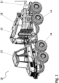
- FIG. 1 is a perspective view of a forestry machine according to an embodiment of the invention.
- Fig. 1 shows a forestry machine 10 according to an embodiment according to the invention, in more detail a forwarder 10.
- the forestry machine 10 according to the invention is described here without a timber load.
- the forestry machine 10 can also comprise another forestry machine, e.g. a combination of a forwarder and harvester or another drive machine suitable for carrying a load.
- the forestry machine 10 can comprise a load space 11 for stacking a timber pile to be transported.
- the forestry machine 10 can additionally comprise a boom structure 12 and a wood handling tool attached to the boom structure 12, such as a load bucket.
- the forestry machine 10 can comprise a rotating pivot device, the so-called rotator, arranged between said boom structure 12 and said wood-handling tool.
- the forestry machine 10 can comprise a cabin 15 and a load screen 13 arranged on the end of the cabin 15 in the load space 11.
- the forestry machine 10 according to an embodiment of the invention is arranged to collect timber from the work piles of the felling location, to transport the collected timber load to the side of a road and to unload the timber load into timber piles.
- the forestry machine 10 can further comprise a moving means 14, which moving means 14 may comprise at least one of the following: wheels arranged on an axle, wheels arranged on a swinging axle, wheels arranged on a tandem axle, a track system or another means known as such to cause the forestry machine to move in relation to its working surface. It is obvious for those skilled in the art that typically the work machine additionally comprises numerous structural and functional components and entities that depend on the work machine type, such as a power source and so forth.
- the forestry machine 10 comprises an arrangement for controlling the unloading of the forestry machine.
- the driver is assisted in the unloading of a timber load 22 of the forestry machine 10 such that the timber load 22 can be cleanly unloaded into timber piles into a desired timber-pile location 20.
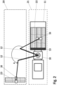
- Fig. 2 shows a top view of an illustration of an arrangement according to an embodiment of the invention for controlling the unloading the load of a forestry machine.
- driver of a forestry machine 10 such as a forwarder 10 selects/identifies a suitable location 20 for a timber pile, e.g. a timber-pile location 20 on the side of a road.
- the driver controls the forestry machine 10 into an area 21 next to said timber-pile location 20.
- the timber load 22 in the load space 11 of the forestry machine 10 has already been justified in the loading step such that the ends of timber are evenly against a load screen 13 of the load space 11 of the forest machine 10.
- the driver of a forestry machine 10 notes down a timber-pile location 20 by means of the boom structure 12 of the forestry machine 10 and the wood-handling tool 16 attached to said boom structure 12.
- the noting down of the timber-pile location 20 can be done e.g. by picking a timber bundle 23 from the timber load 22 of the load space 11 of the forestry machine 10 and by transferring (Arrow A) and unloading said timber bundle 23 on the first edge of the timber-pile location 20, on the left edge in Fig. 2 .
- the control system of the forestry machine 10 then reads that the timber-pile location 20 starts from said unloading location of the timber bundle 23.
- the control system of the forestry machine 10 can also read that the filling direction of the timer pile is in the direction of said unloading location of the timber bundle 23 towards the forestry machine 10, starting from the left edge to the right in Fig. 2 .
- the driver can notify of the filling direction of the timber pile to the control system in some other way, e.g. by a separate command or a certain predetermined control motion. If the driver so desires, they can justify the timber bundle 23 against the load screen 13, if the ends have not been straight against the load screen 13. Preferably, this justifying motion of the timber bundle against the screen can be an automatic or a semiautomatic action.
- the grabbing means of the wood-handling tool 16 e.g. the jaws of a grabber are opened, whereby it is possible for the single timbers in the bundle to justify in the bundle onto the same level.
- the control system of the forestry machine 10 always identifies the location of the wood-handling tool 16 and is able to control the position of the wood-handling tool 16 and the rotation angle of the wood-handling tool 16.
- the position of the wood-handling tool 16 can be calculated based on sensor measuring data, such as on sensor data of the boom structure, or in some other way.
- the control system of the forestry machine 10 is arranged to identify and/or control the position of the grabbing means of the wood-handling tool 16, e.g. the position of the jaws of a grabber.
- the control system of the forestry machine 10 knows beforehand the location of the load screen 13 and, thus, also the distance of the end of a timber bundle justified against the load screen from the wood-handling tool 16.
- the control system can know that location of the load screen 13 e.g. such that the driver controls that wood-handling tool 16 against the screen and commands the control system to register the location of the load screen 13 down.
- Justifying the timber bundle 23 can be acknowledged by the grabber closed action because, when justifying the ends, the wood-handling tool 16 must be opened slightly.
- the measuring apparatus of the forestry machine 10 measures and/or identifies the distance of the end of a timber bundle justified against the load screen 13 from the wood-handling tool 16.
- the control system of the forestry machine 10 knows the distance of the end of a timber bundle from the wood-handling tool 16.
- the control system of the forestry machine 10 thus knows with the aid of the measuring apparatus the distance of the wood-handling tool 16, e.g. a grabber, from the screen irrespective of in which position of the timber load 22 of the load space 11 the wood-handling tool 16 picks timber.
- the control system calculates and notes down the location of the edge of the timber pile. Then, the control system can help the driver to take each timber bundle at an accurate distance from the machine and the edge of the timber pile becomes even and straight.
- the control system of the forest machine 10 can also calculate the height of the timber bundle based on the previous unloading location of the timber bundles 23 of the wood-handling tool 16 and thus adjust the unloading height of the wood-handling tool 16 for each timber bundle 23 almost accurate.
- the control system of the forestry machine 10 can control the rotation angle of the wood-handling tool 16 e.g. by means of the rotation angle of the rotator.
- the control system of the forestry machine 10 also knows the accurate direction of the bundle and the system can turn the timbers in the timber bundle 23 automatically parallel with the pile and the timbers of the timber bundle 23 stay at an angle of 90 degrees in relation to the side of the pile.
- the control system of the forestry machine 10 automatically assists in controlling and unloading of the timber pile 22.
- the control system of the forestry machine 10 calculates a suitable unloading location for each timber bundle picked from the timber load 22 of the load space 11 of the forestry machine 10 by means of the wood-handling tool 16 and controls said timber bundles a bundle at a time into the calculated unloading location neatly in a timber pile.
- a timber pile even and/or straight of its one edge can be provided into a designated timber-pile location 20.
- the forestry machine 10 can leave to pick a new load from the felling area.
- the forestry machine 10 return with a new timber load back to close to the timber-pile location 20 on the side of a road.
- the control system of the forestry machine 10 automatically identifies the location of the forestry machine 10, preferably in relation to the timber pile and the location of the timber-pile location 20, and reads that the forestry machine 10 has returned with a new timber load 22.
- control system of the forestry machine 10 remembers the filling situation of the timber pile in the timber-pile location 20 and automatically assists in unloading the new timber load 22 neatly in the timber pile and controls the timber bundles picked from the timber load 22 of the load space 11 of the forestry machine 10 by means of the wood-handling tool 16 a bundle at a time into an even timber pile in the designated timber-pile location 20. Additionally, the driver can notify the control system of some control command related to the filling of the timber pile e.g. by a separate command or a certain predetermined control motion.
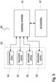
- Fig. 3 shows a block diagram of the structure of a control arrangement of unloading of a forestry machine according to an embodiment of the invention.
- the control arrangement 30 of the unloading of a forestry machine according to an embodiment of the invention comprises a control system 31, a measuring apparatus 32 and actuators 37 of the forestry machine.
- the measuring apparatus 32 of the control arrangement 30 according to the invention comprises at least two measuring devices 33-36, by means of which, it is possible to measure some required measuring variables, such as e.g. the location of the forestry machine 10, preferably in relation to the timber pile, the position of the wood-handling tool 16, preferably in relation to the timber pile and the forestry machine 10 and its rotation angle and the location and rotation angle of the timber bundle picked by means of the wood-handling tool 16.
- Said at least two measuring devices 33-36 of the measuring apparatus 32 can comprise at least one GPS measuring device 33 for defining the location of the forestry machine 10.
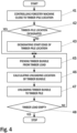
- Fig. 4 shows a block diagram of a method according to an embodiment of the invention for controlling the unloading of a forestry machine.
- the driver first selects/identifies a suitable location 20 for the timber pile, e.g. a timber-pile location 20 on the side of a road, and controls the forestry machine 10 close to the timber-pile location they have selected/identified 41.
- the control system 31 of the forestry machine 10 identified 42 if the timber-pile location has been previously designated or not. If the timber-pile location has not been designated previously, the timber-pile location is next designated 43.
- the driver of a forestry machine 10 notes down a timber-pile location 20 by means of the boom structure 12 of the forestry machine 10 and the wood-handling tool 16 attached to said boom structure 12.
- the start edge of the timber-pile location can be designated 43 e.g. by picking a timber bundle 23 from the timber load 22 of the load space 11 of the forestry machine 10 and by transferring and unloading said timber bundle 23 on the start edge of the timber-pile location 20.
- the forestry machine 10 picks 45 by the wood-handling tool 16 a timber bundle from the timber load 22 of the load space 11.
- the control system 31 of the forestry machine 10 calculates 46 a suitable unloading location for the timber bundle in question and controls said timber bundles a bundle at a time into the calculated 46 suitable unloading where the timber bundle is unloaded 47 neatly in a timber pile.
- the unloading step 45-48 is stopped and the forestry machine 10 can leave to pick a new load from the felling area.
- Fig. 5 shows a top view of an illustration of an alternative arrangement according to an embodiment of the invention for controlling the unloading the load of a forestry machine.
- the driver of a forestry machine 10 such as a forwarder 10 selects/identifies a suitable location 20 for a timber pile and control the forestry machine 10 in an area 21 next to said timber-pile location 20.
- the driver of the forestry machine 10 designated the timber-pile location 20 by means of the boom structure 12 of the forestry machine 10 and the wood-handling tool 16 attached to said boom structure 12.
- the noting down of the start edge of the timber-pile location 20 can be done e.g. by picking a first timber bundle 23 from the timber load 22 of the load space 11 of the forestry machine 10 and by transferring (Arrow A) and unloading said first timber bundle 23 on the first edge of the timber-pile location 20, on the left edge in Fig. 5 .
- the noting down of the stop edge of the timber-pile location 20 can be done e.g. by picking a timber bundle 24 from the timber load 22 of the load space 11 of the forestry machine 10 and by transferring (Arrow B) and unloading said timber bundle 24 on opposite second edge of the timber-pile location 20, on the right edge in Fig. 5 .
- the control system of the forestry machine 10 then reads that the timber-pile location 20 starts from said unloading location of said first timber bundle 23 and stops in said unloading location of the second timber bundle 24.
- the control system of the forestry machine 10 can also thus read that the timber pile can be filled evenly between the above-mentioned unloading location of the timber bundles 23, 24.
- the control system of the forestry machine 10 automatically assists in controlling and unloading of the timber pile 22.
- the control system of the forestry machine 10 calculates a suitable unloading location for each timber bundle picked from the timber load 22 of the load space 11 of the forestry machine 10 by means of the wood-handling tool 16 and controls said timber bundles a bundle at a time into the calculated unloading location neatly in a timber pile.
- a timber pile even and/or straight of its one edge can be provided into a designated timber-pile location 20.
- the forestry machine 10 can leave to pick a new load from the felling area.
- the forestry machine 10 return with a new timber load back to close to the timber-pile location 20 on the side of a road.
- the control system of the forestry machine 10 automatically identifies the location of the forestry machine 10, preferably in relation to the timber pile and the location of the timber-pile location 20, and reads that the forestry machine 10 has returned with a new timber load 22.
- control system of the forestry machine 10 remembers the filling situation of the timber pile in the timber-pile location 20 and automatically assists in unloading the new timber load 22 neatly in the timber pile and controls the timber bundles picked from the timber load 22 of the load space 11 of the forestry machine 10 by means of the wood-handling tool 16 a bundle at a time into an even timber pile in the designated timber-pile location 20. Additionally, the driver can notify the control system of some control command related to the filling of the timber pile e.g. by a separate command or a certain predetermined control motion.
- Fig. 6 shows a block diagram of a method according to an embodiment of the invention for controlling the unloading of a forestry machine.
- the driver first selects/identifies a suitable location 20 for the timber pile, e.g. a timber-pile location 20 on the side of a road, and controls the forestry machine 10 close to the timber-pile location they have selected/identified 41.
- the control system 31 of the forestry machine 10 identifies 42 if the timber-pile location has been previously designated or not. If the timber-pile location has not been designated previously, the timber-pile location is next designated 43, 44.
- the driver of a forestry machine 10 notes down 43, 44 a timber-pile location 20 by means of the boom structure 12 of the forestry machine 10 and the wood-handling tool 16 attached to said boom structure 12.
- the start edge of the timber-pile location can be designated 43 e.g. by picking a first timber bundle 23 from the timber load 22 of the load space 11 of the forestry machine 10 and by transferring and unloading said timber bundle 23 on the start edge of the timber-pile location 20.
- the stop edge of the timber-pile location can be designated 44 e.g. by picking a second timber bundle 24 from the timber load 22 of the load space 11 of the forestry machine 10 and by transferring and unloading said timber bundle 24 on the stop edge of the timber-pile location 20.
- the forestry machine 10 picks 45 by the wood-handling tool 16 a timber bundle from the timber load 22 of the load space 11.
- the control system 31 of the forestry machine 10 calculates 46 a suitable unloading location for the timber bundle in question and controls said timber bundles a bundle at a time into the calculated 46 suitable unloading where the timber bundle is unloaded 47 neatly in a timber pile.
- the unloading step 45-48 is stopped and the forestry machine 10 can leave to pick a new load from the felling area.
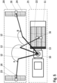
- Fig. 7 shows a top view of an illustration of an unloading situation of a forestry machine according to an embodiment of the invention.
- the forestry machine 10 is placing the timber bundle 25 in place by means of the boom structure 12 and the wood-handling tool 16.
- Fig. 8 shows a perspective view of an illustration of an unloading situation of a forestry machine according to an embodiment of the invention.
- the forestry machine 10 is placing the timber bundle 25 in place by means of the boom structure 12 and the wood-handling tool 16.
- the load screen is designated by reference number 13.
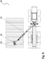
- Fig. 9 shows a first top view of an illustration the progress of the unloading of a forestry machine according to an embodiment of the invention.
- the forestry machine 10 is placing the timber bundle 25 in place by means of the boom structure 12 and the wood-handling tool 16.
- the unloading step of the load shown in Fig. 9 there is still timber load left in the load space of the forestry machine.
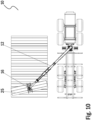
- Fig. 10 shows a second top view of an illustration the progress of the unloading of a forestry machine according to an embodiment of the invention.
- the forestry machine 10 is placing the last timber bundle 25 of the timber load in place by means of the boom structure 12 and the wood-handling tool 16.
- the control system of the forestry machine has not yet controlled the wood-handling tool to turn the timber bundle 25 straight into a suitable timber-pile location.
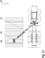
- Fig. 11 shows a third top view of an illustration the progress of the unloading of a forestry machine according to an embodiment of the invention.
- the forestry machine 10 ready to unload the last timber bundle 25 of the timber load in place by means of the boom structure 12 and the wood-handling tool 16.
- the control system of the forestry machine has now controlled the wood-handling tool to turn the timber bundle 25 straight and is thus ready to unload the timber bundle 25 into a suitable timber-pile location.
- the control system of the unloading of a timber load according to an arrangement according to the invention facilitates the unloading of a timber load considerably.
- the control system of the forestry machine according to the arrangement according to the invention automatically assists in controlling and unloading of a timber pile into a designated timber-pile location.
- the control system of the forestry machine assists the driver in taking the timber bundle always on the accurate distance from the machine and the edge of the timber pile then becomes straight irrespective of the position in which the wood-handling tool grabs the timber bundle in their length direction.
Landscapes
- Engineering & Computer Science (AREA)
- Mechanical Engineering (AREA)
- Life Sciences & Earth Sciences (AREA)
- Transportation (AREA)
- Ecology (AREA)
- Environmental Sciences (AREA)
- Forests & Forestry (AREA)
- Biodiversity & Conservation Biology (AREA)
- Structural Engineering (AREA)
- General Engineering & Computer Science (AREA)
- Civil Engineering (AREA)
- Mining & Mineral Resources (AREA)
- Public Health (AREA)
- Health & Medical Sciences (AREA)
- Robotics (AREA)
- Operation Control Of Excavators (AREA)
- Conveying And Assembling Of Building Elements In Situ (AREA)
- Stacking Of Articles And Auxiliary Devices (AREA)
- Loading Or Unloading Of Vehicles (AREA)
Claims (15)
- Anordnung (30) zur Steuerung des Entladens einer Forstmaschine (10), wobei die Forstmaschine (10) ein Ladevolumen (11) für Nutzholzlast (22), eine Auslegerstruktur (12) und ein Holzhandhabungswerkzeug (16) umfasst, das an der Auslegerstruktur angebracht ist, wobei die Anordnung (30) ferner ein Steuersystem (31) und eine Messvorrichtung (32) der Forstmaschine (10) umfasst, wobei:- die Messvorrichtung (32) dazu eingerichtet ist, den Ort der Forstmaschine (10) und den Drehwinkel der Auslegerstruktur (12) und die Position der einzelnen Auslegerteile der Auslegerstruktur (12) und die Position des Holzhandhabungswerkzeugs (16) zu messen,
wobei- das Steuersystem (31) eingerichtet ist zum:- Definieren und Verzeichnen des Orts (20) eines Nutzholzstapels,dadurch gekennzeichnet, dass das Steuersystem ferner eingerichtet ist zum:- Berechnen und Verzeichnen der Position eines Rands des Nutzholzstapels,- Steuern des Holzhandhabungswerkzeugs (16) zum Aufnehmen eines Nutzholzbündels (23) von der Nutzholzlast (22),- Berechnen des Abstands eines auf ein Ladegitter (13) ausgerichteten Endes des Nutzholzbündels von dem Holzhandhabungswerkzeug (16),- Berechnen eines Entladeorts für das Nutzholzbündel auf einem Nutzholzstapel gleichmäßig und gerade von seinem einen Rand an dem definierten Nutzholzstapelort (20), und- Steuern und Entladen des Nutzholzbündels an dem berechneten Entladeort auf dem Nutzholzstapel. - Anordnung (30) nach Anspruch 1, wobei die Messvorrichtung (32) dazu eingerichtet ist, den Bewegungsraum einzelner Auslegerteile der Auslegerstruktur (12) zu messen.
- Anordnung (30) nach Anspruch 1 oder 2, wobei die Messvorrichtung (32) zum Messen des Drehwinkels des Holzhandhabungswerkzeugs (16) eingerichtet ist.
- Anordnung (30) nach einem der vorhergehenden Ansprüche 1 bis 3, wobei das Steuersystem (31) dazu eingerichtet ist, den Drehwinkel der Auslegerstruktur (12) und die Position einzelner Auslegerteile der Auslegerstruktur (12) und den Ort des Holzhandhabungswerkzeugs (16) zu steuern.
- Anordnung (30) nach einem der vorhergehenden Ansprüche 1 bis 4, wobei die Messvorrichtung (32) dazu eingerichtet ist, die Position der Greifermittel des Holzhandhabungswerkzeugs (16) zu messen.
- Anordnung (30) nach Anspruch 5, wobei das Steuersystem (31) dazu eingerichtet ist, die Position der Greifermittel des Holzhandhabungswerkzeugs (16) zu identifizieren und/oder zu steuern.
- Anordnung (30) nach einem der vorhergehenden Ansprüche 1 bis 6, wobei das Steuersystem (31) dazu eingerichtet ist, die Höhe des Nutzholzstapels basierend auf dem Entladeort entladener Nutzholzbündel zu berechnen.
- Anordnung (30) nach einem der vorhergehenden Ansprüche 1 bis 7, wobei das Steuersystem (31) dazu eingerichtet ist, den Ort der Forstmaschine (10) und/oder den Ort des Nutzholzstapels (20) automatisch zu identifizieren.
- Anordnung (30) nach einem der vorhergehenden Ansprüche 1 bis 8, wobei das Steuersystem (31) dazu eingerichtet ist, die Position der Auslegerstruktur (12) der Forstmaschine (10) und/oder ihren Drehwinkel durch Identifizieren der Position und/oder des Bewegungsraums einzelner Auslegerteile automatisch zu identifizieren.
- Anordnung (30) nach einem der vorhergehenden Ansprüche 1 bis 9, wobei die Forstmaschine (10) ein Forwarder (10) ist.
- Verfahren zur Steuerung des Entladens von einer Forstmaschine (10), wobei die Forstmaschine (10) ein Ladevolumen (11) für Nutzholzlast (22), eine Auslegerstruktur (12), ein Holzhandhabungswerkzeug (16), das an der Auslegerstruktur angebracht ist, ein Steuersystem (31) und eine Messvorrichtung (32) umfasst, wobei das Verfahren die folgenden Schritte umfasst:- Definieren und Verzeichnen (43), (44) des Orts (20) eines Nutzholzstapels,dadurch gekennzeichnet, dass das Verfahren ferner die folgenden Schritte umfasst:- Berechnen und Verzeichnen der Position eines Rands des Nutzholzstapels,- Aufnehmen (45), durch das Holzhandhabungswerkzeug (16), eines Nutzholzbündels (23) von der Nutzholzlast (22),- Berechnen (46) des Abstands eines auf ein Ladegitter (13) ausgerichteten Endes des Nutzholzbündels von dem Holzhandhabungswerkzeug (16),- Berechnen eines Entladeorts für das Nutzholzbündel auf einem Nutzholzstapel gleichmäßig und gerade von seinem einen Rand an dem definierten Nutzholzstapelort (20), und- Steuern und Entladen (47) des Nutzholzbündels an dem berechneten Entladeort auf dem Nutzholzstapel.
- Verfahren nach Anspruch 11, wobei der Ort (20) des Nutzholzstapels durch Aufnehmen eines Nutzholzbündels (23) von der Nutzholzlast (22) von dem Ladevolumen (11) und durch Überführen und Entladen des Nutzholzstapels (23) auf dem ersten Rand des Nutzholzstapelorts (20) verzeichnet (43), (44) wird.
- Verfahren nach Anspruch 11, wobei der Ort (20) des Nutzholzstapels durch Aufnehmen eines ersten Nutzholzbündels (23) von der Nutzholzlast (22) des Ladevolumens (11) und durch Überführen und Entladen des ersten Nutzholzbündels (23) auf dem ersten Rand des Nutzholzstapelorts (20) und durch Aufnehmen eines zweiten Nutzholzbündels (24) von der Nutzholzlast (22) des Ladevolumens (11) und durch Überführen und Entladen des zweiten Nutzholzbündels (24) auf dem zweiten Rand des Nutzholzstapelorts (20) verzeichnet (43), (44) wird.
- Verfahren nach einem der Ansprüche 11 bis 13, wobei das Verfahren einen Schritt zum Steuern des Holzhandhabungswerkzeugs (16), das gegen das Ladegitter (13) gesteuert wird, und Aufzeichnen des Orts des Ladegitters (13) umfasst.
- Verfahren nach einem der vorhergehenden Ansprüche 11 bis 14, wobei die Forstmaschine (10) ein Forwarder (10) ist.
Applications Claiming Priority (2)
| Application Number | Priority Date | Filing Date | Title |
|---|---|---|---|
| FI20185725A FI128475B (fi) | 2018-08-30 | 2018-08-30 | Järjestely ja menetelmä metsäkoneen kuorman purkamisen hallintaan |
| PCT/FI2019/050615 WO2020043952A1 (en) | 2018-08-30 | 2019-08-29 | Arrangement and method for managing unloading of a load of a forestry machine |
Publications (4)
| Publication Number | Publication Date |
|---|---|
| EP3843530A1 EP3843530A1 (de) | 2021-07-07 |
| EP3843530A4 EP3843530A4 (de) | 2021-11-10 |
| EP3843530B1 true EP3843530B1 (de) | 2025-01-22 |
| EP3843530C0 EP3843530C0 (de) | 2025-01-22 |
Family
ID=69644790
Family Applications (1)
| Application Number | Title | Priority Date | Filing Date |
|---|---|---|---|
| EP19854463.7A Active EP3843530B1 (de) | 2018-08-30 | 2019-08-29 | Anordnung und verfahren zur verwaltung des entladens einer last einer forstmaschine |
Country Status (6)
| Country | Link |
|---|---|
| US (1) | US12232455B2 (de) |
| EP (1) | EP3843530B1 (de) |
| BR (1) | BR112021002925A2 (de) |
| CA (1) | CA3107402A1 (de) |
| FI (1) | FI128475B (de) |
| WO (1) | WO2020043952A1 (de) |
Families Citing this family (7)
| Publication number | Priority date | Publication date | Assignee | Title |
|---|---|---|---|---|
| FI128122B (fi) * | 2018-08-29 | 2019-10-15 | Ponsse Oyj | Ohjausjärjestely ja menetelmä metsäkoneen ohjaamiseksi |
| EP4094984B1 (de) * | 2021-05-28 | 2025-02-19 | EPSILON Kran GmbH. | Fahrzeugaufbau |
| DE102022205673B4 (de) | 2022-06-02 | 2024-03-14 | Zf Friedrichshafen Ag | Vorrichtung zum Ermitteln der optimalen Position eines Holztransporters in Bezug auf ein Lagerziel |
| EP4305954A1 (de) * | 2022-07-11 | 2024-01-17 | Deere & Company | System und verfahren zur erfassung der lasthöhe |
| DE102023109935A1 (de) * | 2023-04-19 | 2024-10-24 | Psiori GmbH | Verfahren zum autonomen Betrieb eines Krans, autonom betreibbarer Kran sowie Nachrüst-Set zur Realisierung eines autonom arbeitenden Krans |
| FI131432B1 (en) * | 2023-05-30 | 2025-04-22 | Deere & Co | Automatic transfer of an articulated boom of a forwarder for handling logs |
| US20250162842A1 (en) * | 2023-11-16 | 2025-05-22 | Deere & Company | System & Method to Improve Productivity in Forestry Work Machine |
Citations (9)
| Publication number | Priority date | Publication date | Assignee | Title |
|---|---|---|---|---|
| WO1989000808A1 (en) | 1987-07-24 | 1989-02-09 | Ösa Ab | Method for handling and transporting logs from felling site to consumer, and road vehicle for carrying out the method |
| WO2004020938A1 (en) | 2002-08-27 | 2004-03-11 | Dralle Aps | A method and a system for automatic measurement and tracking of logs, industrial wood and boards |
| WO2014195585A1 (en) | 2013-06-05 | 2014-12-11 | Ponsse Oyj | Method and arrangement for measuring timber |
| EP2932823A1 (de) | 2014-04-17 | 2015-10-21 | John Deere Forestry OY | Materialmanipulationsvorrichtung, Arbeitsfahrzeug und Verfahren |
| EP2939529A1 (de) | 2014-04-29 | 2015-11-04 | John Deere Forestry Oy | Verfahren und System zur Steuerung des Krans einer Forstmaschine |
| EP2939530A1 (de) | 2014-04-29 | 2015-11-04 | John Deere Forestry Oy | Verfahren und System zur Steuerung des Krans einer Forstmaschine |
| EP2987399A1 (de) | 2014-08-22 | 2016-02-24 | John Deere Forestry Oy | Verfahren und System zur Ausrichtung eines Werkzeugs |
| EP3349141A1 (de) * | 2017-01-11 | 2018-07-18 | Deere & Company | Laststeuerungsvorrichtung und -verfahren |
| WO2018130747A1 (en) | 2017-01-10 | 2018-07-19 | Ponsse Oyj | Method and arrangement to control the operation of a wood-handling device in a work machine, and a forest machine |
Family Cites Families (16)
| Publication number | Priority date | Publication date | Assignee | Title |
|---|---|---|---|---|
| FI7189A (fi) | 1919-02-15 | Postileimasin | ||
| US6360166B1 (en) * | 2000-04-24 | 2002-03-19 | Caterpillar Lnc. | Apparatus and method for removing logs from a forestry site |
| FI111350B (fi) * | 2002-01-16 | 2003-07-15 | Timberjack Oy | Työkoneen kuormatilan dimensioiden muuttaminen |
| US7794188B2 (en) * | 2003-11-07 | 2010-09-14 | Western Trailer Co. | Method, apparatus and system for pre-bunking cut timber and transporting wood residuals |
| US20050111962A1 (en) * | 2003-11-07 | 2005-05-26 | Whitehead Jerald M. | Method, apparatus and system for pre-bunking cut timber and transporting wood residuals |
| US8407157B2 (en) | 2003-12-22 | 2013-03-26 | Deere & Company | Locating harvested material within a work area |
| US20090229708A1 (en) * | 2008-03-12 | 2009-09-17 | Barrier West, Inc. | System and method for energy-efficient on-site processing of forestry brushwood |
| FI20090447A7 (fi) * | 2009-11-26 | 2011-05-27 | Ponsse Oyj | Menetelmä ja laite metsäkoneen yhteydessä |
| SE535026C2 (sv) * | 2010-01-19 | 2012-03-20 | Green Wood Logistics Ab | Lastbärare |
| FI122872B (fi) * | 2011-01-28 | 2012-08-15 | Ponsse Oyj | Menetelmä punnitusjärjestelmän tarkistuspunnituksessa ja ohjelmistotuote sekä järjestely punnitusjärjestelmän tarkistuspunnituksessa ja materiaalinkäsittelykone |
| FI124565B (fi) * | 2012-05-31 | 2014-10-15 | Ponsse Oyj | Metsätyöyksikön vakautus |
| US9400163B2 (en) * | 2012-06-06 | 2016-07-26 | Deere & Company | Method and apparatus for processing a length of material |
| FI20135085L (fi) * | 2013-01-29 | 2014-07-30 | John Deere Forestry Oy | Menetelmä ja järjestelmä työkoneen puomiston ohjaamiseksi kärkiohjauksella |
| GB201317471D0 (en) * | 2013-10-02 | 2013-11-13 | Hook Up Solutions Llp | Trolley |
| FI125464B (en) | 2014-03-18 | 2015-10-15 | Novatron Oy | Arrangement and method for positioning the machine |
| FI128066B (fi) * | 2017-06-06 | 2019-08-30 | Ponsse Oyj | Järjestely metsäkoneessa ja metsäkone |
-
2018
- 2018-08-30 FI FI20185725A patent/FI128475B/fi active IP Right Review Request
-
2019
- 2019-08-29 EP EP19854463.7A patent/EP3843530B1/de active Active
- 2019-08-29 CA CA3107402A patent/CA3107402A1/en active Pending
- 2019-08-29 US US17/272,041 patent/US12232455B2/en active Active
- 2019-08-29 BR BR112021002925-7A patent/BR112021002925A2/pt not_active Application Discontinuation
- 2019-08-29 WO PCT/FI2019/050615 patent/WO2020043952A1/en not_active Ceased
Patent Citations (9)
| Publication number | Priority date | Publication date | Assignee | Title |
|---|---|---|---|---|
| WO1989000808A1 (en) | 1987-07-24 | 1989-02-09 | Ösa Ab | Method for handling and transporting logs from felling site to consumer, and road vehicle for carrying out the method |
| WO2004020938A1 (en) | 2002-08-27 | 2004-03-11 | Dralle Aps | A method and a system for automatic measurement and tracking of logs, industrial wood and boards |
| WO2014195585A1 (en) | 2013-06-05 | 2014-12-11 | Ponsse Oyj | Method and arrangement for measuring timber |
| EP2932823A1 (de) | 2014-04-17 | 2015-10-21 | John Deere Forestry OY | Materialmanipulationsvorrichtung, Arbeitsfahrzeug und Verfahren |
| EP2939529A1 (de) | 2014-04-29 | 2015-11-04 | John Deere Forestry Oy | Verfahren und System zur Steuerung des Krans einer Forstmaschine |
| EP2939530A1 (de) | 2014-04-29 | 2015-11-04 | John Deere Forestry Oy | Verfahren und System zur Steuerung des Krans einer Forstmaschine |
| EP2987399A1 (de) | 2014-08-22 | 2016-02-24 | John Deere Forestry Oy | Verfahren und System zur Ausrichtung eines Werkzeugs |
| WO2018130747A1 (en) | 2017-01-10 | 2018-07-19 | Ponsse Oyj | Method and arrangement to control the operation of a wood-handling device in a work machine, and a forest machine |
| EP3349141A1 (de) * | 2017-01-11 | 2018-07-18 | Deere & Company | Laststeuerungsvorrichtung und -verfahren |
Non-Patent Citations (3)
| Title |
|---|
| BJÖRN LÖFGREN: "KTH Industrial Engineering and Management Kinematic Control of Redundant Knuckle Booms Kinematic Control of Redundant Knuckle Booms with Automatic Path-Following Functions", DOCTORAL THESIS, 9 November 2009 (2009-11-09), XP055696955, Retrieved from the Internet <URL:https://www.diva-portal.org/smash/record.jsf?pid=diva2%3A277303&dswid=-2398> [retrieved on 20200519] * |
| D4 - PUBLICATION "KORJUUN SUUNNITTELU JA TOTEUTUS" |
| D5 - PUBLICATION "KONEELLINEN PUUNKORJUU" |
Also Published As
| Publication number | Publication date |
|---|---|
| FI128475B (fi) | 2020-06-15 |
| FI20185725A1 (fi) | 2020-03-01 |
| WO2020043952A1 (en) | 2020-03-05 |
| EP3843530A4 (de) | 2021-11-10 |
| US12232455B2 (en) | 2025-02-25 |
| US20210345560A1 (en) | 2021-11-11 |
| EP3843530A1 (de) | 2021-07-07 |
| EP3843530C0 (de) | 2025-01-22 |
| BR112021002925A2 (pt) | 2021-05-11 |
| CA3107402A1 (en) | 2020-03-05 |
Similar Documents
| Publication | Publication Date | Title |
|---|---|---|
| EP3843530B1 (de) | Anordnung und verfahren zur verwaltung des entladens einer last einer forstmaschine | |
| US11937554B2 (en) | Method and arrangement to control the operation of a wood-handling device in a work machine, and a forest machine | |
| US8430621B2 (en) | Control of a boom construction and a tool articulated thereto | |
| EP2736810A2 (de) | Vorrichtung und verfahren zum entpacken und zuführen von flach gefalteten und aufrecht stehenden packungsmänteln | |
| SE1551212A1 (sv) | Anordning för buntning av okvistade träddelar | |
| US20240010475A1 (en) | Load Height Detection System and Method | |
| CA3147842A1 (en) | Method and system in a forest machine | |
| US3385333A (en) | Vertical logging machine | |
| EP4486111A1 (de) | Verfahren und system zum betreiben einer forstmaschine | |
| US20240397883A1 (en) | Automatic transfer of an articulated boom of a forwarder for handling logs | |
| RU2814827C2 (ru) | Система и способ управления разгрузкой лесотехнической машины | |
| FI131551B1 (fi) | Menetelmä ja ohjausjärjestelmä harvesterin puomiston ohjaamiseksi | |
| EP4471689B1 (de) | Überwachung von geernteten stämmen und stämmestapeln an einem arbeitsort | |
| Knobloch et al. | Development and evaluation of a felling head for a light forest crawler | |
| DE102021113435A1 (de) | System zur automatischen Kommissionierung von Stückgütern | |
| US20210339721A1 (en) | Arrangement and method for controlling working brakes of a hydraulically or electrically operated work machine | |
| FI131266B1 (fi) | Menetelmä ja ohjausjärjestelmä metsätyökoneen puunkäsittelylaitteen toiminnan ohjaamiseksi | |
| FI88853B (fi) | Foerfarande och anordning foer skogsgallring | |
| US20250287887A1 (en) | Method for measuring and analyzing a forest area for a forestry vehicle | |
| WO2025012517A1 (en) | Method for processing wood in wood processing device of forest work machine and control system for controlling operation of wood processing device | |
| FI131287B1 (fi) | Menetelmä ja järjestely puunkäsittelylaitteen toiminnan ohjaamiseksi työkoneessa ja metsäkone | |
| CN118901537A (zh) | 伐木机 |
Legal Events
| Date | Code | Title | Description |
|---|---|---|---|
| STAA | Information on the status of an ep patent application or granted ep patent |
Free format text: STATUS: THE INTERNATIONAL PUBLICATION HAS BEEN MADE |
|
| STAA | Information on the status of an ep patent application or granted ep patent |
Free format text: STATUS: REQUEST FOR EXAMINATION WAS MADE |
|
| PUAI | Public reference made under article 153(3) epc to a published international application that has entered the european phase |
Free format text: ORIGINAL CODE: 0009012 |
|
| 17P | Request for examination filed |
Effective date: 20210315 |
|
| AK | Designated contracting states |
Kind code of ref document: A1 Designated state(s): AL AT BE BG CH CY CZ DE DK EE ES FI FR GB GR HR HU IE IS IT LI LT LU LV MC MK MT NL NO PL PT RO RS SE SI SK SM TR |
|
| A4 | Supplementary search report drawn up and despatched |
Effective date: 20211011 |
|
| RIC1 | Information provided on ipc code assigned before grant |
Ipc: E02F 9/26 20060101ALI20211005BHEP Ipc: B66C 23/00 20060101ALI20211005BHEP Ipc: B66C 1/58 20060101ALI20211005BHEP Ipc: B66C 13/08 20060101ALI20211005BHEP Ipc: E02F 3/43 20060101ALI20211005BHEP Ipc: B66C 23/42 20060101ALI20211005BHEP Ipc: A01G 23/00 20060101AFI20211005BHEP |
|
| DAV | Request for validation of the european patent (deleted) | ||
| DAX | Request for extension of the european patent (deleted) | ||
| STAA | Information on the status of an ep patent application or granted ep patent |
Free format text: STATUS: EXAMINATION IS IN PROGRESS |
|
| 17Q | First examination report despatched |
Effective date: 20231212 |
|
| GRAP | Despatch of communication of intention to grant a patent |
Free format text: ORIGINAL CODE: EPIDOSNIGR1 |
|
| STAA | Information on the status of an ep patent application or granted ep patent |
Free format text: STATUS: GRANT OF PATENT IS INTENDED |
|
| INTG | Intention to grant announced |
Effective date: 20240905 |
|
| GRAS | Grant fee paid |
Free format text: ORIGINAL CODE: EPIDOSNIGR3 |
|
| GRAA | (expected) grant |
Free format text: ORIGINAL CODE: 0009210 |
|
| STAA | Information on the status of an ep patent application or granted ep patent |
Free format text: STATUS: THE PATENT HAS BEEN GRANTED |
|
| AK | Designated contracting states |
Kind code of ref document: B1 Designated state(s): AL AT BE BG CH CY CZ DE DK EE ES FI FR GB GR HR HU IE IS IT LI LT LU LV MC MK MT NL NO PL PT RO RS SE SI SK SM TR |
|
| REG | Reference to a national code |
Ref country code: GB Ref legal event code: FG4D |
|
| REG | Reference to a national code |
Ref country code: CH Ref legal event code: EP |
|
| REG | Reference to a national code |
Ref country code: IE Ref legal event code: FG4D |
|
| REG | Reference to a national code |
Ref country code: DE Ref legal event code: R096 Ref document number: 602019065211 Country of ref document: DE |
|
| U01 | Request for unitary effect filed |
Effective date: 20250210 |
|
| U07 | Unitary effect registered |
Designated state(s): AT BE BG DE DK EE FI FR IT LT LU LV MT NL PT RO SE SI Effective date: 20250214 |
|
| PG25 | Lapsed in a contracting state [announced via postgrant information from national office to epo] |
Ref country code: RS Free format text: LAPSE BECAUSE OF FAILURE TO SUBMIT A TRANSLATION OF THE DESCRIPTION OR TO PAY THE FEE WITHIN THE PRESCRIBED TIME-LIMIT Effective date: 20250422 |
|
| PG25 | Lapsed in a contracting state [announced via postgrant information from national office to epo] |
Ref country code: PL Free format text: LAPSE BECAUSE OF FAILURE TO SUBMIT A TRANSLATION OF THE DESCRIPTION OR TO PAY THE FEE WITHIN THE PRESCRIBED TIME-LIMIT Effective date: 20250122 |
|
| PG25 | Lapsed in a contracting state [announced via postgrant information from national office to epo] |
Ref country code: ES Free format text: LAPSE BECAUSE OF FAILURE TO SUBMIT A TRANSLATION OF THE DESCRIPTION OR TO PAY THE FEE WITHIN THE PRESCRIBED TIME-LIMIT Effective date: 20250122 |
|
| PG25 | Lapsed in a contracting state [announced via postgrant information from national office to epo] |
Ref country code: NO Free format text: LAPSE BECAUSE OF FAILURE TO SUBMIT A TRANSLATION OF THE DESCRIPTION OR TO PAY THE FEE WITHIN THE PRESCRIBED TIME-LIMIT Effective date: 20250422 Ref country code: IS Free format text: LAPSE BECAUSE OF FAILURE TO SUBMIT A TRANSLATION OF THE DESCRIPTION OR TO PAY THE FEE WITHIN THE PRESCRIBED TIME-LIMIT Effective date: 20250522 |
|
| PG25 | Lapsed in a contracting state [announced via postgrant information from national office to epo] |
Ref country code: HR Free format text: LAPSE BECAUSE OF FAILURE TO SUBMIT A TRANSLATION OF THE DESCRIPTION OR TO PAY THE FEE WITHIN THE PRESCRIBED TIME-LIMIT Effective date: 20250122 |
|
| PG25 | Lapsed in a contracting state [announced via postgrant information from national office to epo] |
Ref country code: GR Free format text: LAPSE BECAUSE OF FAILURE TO SUBMIT A TRANSLATION OF THE DESCRIPTION OR TO PAY THE FEE WITHIN THE PRESCRIBED TIME-LIMIT Effective date: 20250423 |
|
| U20 | Renewal fee for the european patent with unitary effect paid |
Year of fee payment: 7 Effective date: 20250826 |
|
| PG25 | Lapsed in a contracting state [announced via postgrant information from national office to epo] |
Ref country code: SM Free format text: LAPSE BECAUSE OF FAILURE TO SUBMIT A TRANSLATION OF THE DESCRIPTION OR TO PAY THE FEE WITHIN THE PRESCRIBED TIME-LIMIT Effective date: 20250122 |
|
| PGFP | Annual fee paid to national office [announced via postgrant information from national office to epo] |
Ref country code: GB Payment date: 20250822 Year of fee payment: 7 |
|
| PG25 | Lapsed in a contracting state [announced via postgrant information from national office to epo] |
Ref country code: CZ Free format text: LAPSE BECAUSE OF FAILURE TO SUBMIT A TRANSLATION OF THE DESCRIPTION OR TO PAY THE FEE WITHIN THE PRESCRIBED TIME-LIMIT Effective date: 20250122 |
|
| PLBI | Opposition filed |
Free format text: ORIGINAL CODE: 0009260 |
|
| PG25 | Lapsed in a contracting state [announced via postgrant information from national office to epo] |
Ref country code: SK Free format text: LAPSE BECAUSE OF FAILURE TO SUBMIT A TRANSLATION OF THE DESCRIPTION OR TO PAY THE FEE WITHIN THE PRESCRIBED TIME-LIMIT Effective date: 20250122 |
|
| PLAX | Notice of opposition and request to file observation + time limit sent |
Free format text: ORIGINAL CODE: EPIDOSNOBS2 |
|
| 26 | Opposition filed |
Opponent name: JOHN DEERE FORESTRY OY Effective date: 20251021 |
|
| PLBB | Reply of patent proprietor to notice(s) of opposition received |
Free format text: ORIGINAL CODE: EPIDOSNOBS3 |