EP3835552B1 - Turbinenstator einer dampfturbine und entsprechende dampfturbine - Google Patents
Turbinenstator einer dampfturbine und entsprechende dampfturbine Download PDFInfo
- Publication number
- EP3835552B1 EP3835552B1 EP19867806.2A EP19867806A EP3835552B1 EP 3835552 B1 EP3835552 B1 EP 3835552B1 EP 19867806 A EP19867806 A EP 19867806A EP 3835552 B1 EP3835552 B1 EP 3835552B1
- Authority
- EP
- European Patent Office
- Prior art keywords
- partition plate
- protruding portion
- radial direction
- circumferential surface
- half partition
- Prior art date
- Legal status (The legal status is an assumption and is not a legal conclusion. Google has not performed a legal analysis and makes no representation as to the accuracy of the status listed.)
- Active
Links
Images


Classifications
-
- F—MECHANICAL ENGINEERING; LIGHTING; HEATING; WEAPONS; BLASTING
- F01—MACHINES OR ENGINES IN GENERAL; ENGINE PLANTS IN GENERAL; STEAM ENGINES
- F01D—NON-POSITIVE DISPLACEMENT MACHINES OR ENGINES, e.g. STEAM TURBINES
- F01D25/00—Component parts, details, or accessories, not provided for in, or of interest apart from, other groups
- F01D25/24—Casings; Casing parts, e.g. diaphragms, casing fastenings
- F01D25/246—Fastening of diaphragms or stator-rings
-
- F—MECHANICAL ENGINEERING; LIGHTING; HEATING; WEAPONS; BLASTING
- F01—MACHINES OR ENGINES IN GENERAL; ENGINE PLANTS IN GENERAL; STEAM ENGINES
- F01D—NON-POSITIVE DISPLACEMENT MACHINES OR ENGINES, e.g. STEAM TURBINES
- F01D11/00—Preventing or minimising internal leakage of working-fluid, e.g. between stages
- F01D11/02—Preventing or minimising internal leakage of working-fluid, e.g. between stages by non-contact sealings, e.g. of labyrinth type
-
- F—MECHANICAL ENGINEERING; LIGHTING; HEATING; WEAPONS; BLASTING
- F01—MACHINES OR ENGINES IN GENERAL; ENGINE PLANTS IN GENERAL; STEAM ENGINES
- F01D—NON-POSITIVE DISPLACEMENT MACHINES OR ENGINES, e.g. STEAM TURBINES
- F01D9/00—Stators
- F01D9/02—Nozzles; Nozzle boxes; Stator blades; Guide conduits, e.g. individual nozzles
- F01D9/04—Nozzles; Nozzle boxes; Stator blades; Guide conduits, e.g. individual nozzles forming ring or sector
- F01D9/047—Nozzle boxes
-
- F—MECHANICAL ENGINEERING; LIGHTING; HEATING; WEAPONS; BLASTING
- F01—MACHINES OR ENGINES IN GENERAL; ENGINE PLANTS IN GENERAL; STEAM ENGINES
- F01D—NON-POSITIVE DISPLACEMENT MACHINES OR ENGINES, e.g. STEAM TURBINES
- F01D9/00—Stators
- F01D9/02—Nozzles; Nozzle boxes; Stator blades; Guide conduits, e.g. individual nozzles
- F01D9/04—Nozzles; Nozzle boxes; Stator blades; Guide conduits, e.g. individual nozzles forming ring or sector
- F01D9/048—Nozzles; Nozzle boxes; Stator blades; Guide conduits, e.g. individual nozzles forming ring or sector for radial admission
-
- F—MECHANICAL ENGINEERING; LIGHTING; HEATING; WEAPONS; BLASTING
- F05—INDEXING SCHEMES RELATING TO ENGINES OR PUMPS IN VARIOUS SUBCLASSES OF CLASSES F01-F04
- F05D—INDEXING SCHEME FOR ASPECTS RELATING TO NON-POSITIVE-DISPLACEMENT MACHINES OR ENGINES, GAS-TURBINES OR JET-PROPULSION PLANTS
- F05D2220/00—Application
- F05D2220/30—Application in turbines
- F05D2220/31—Application in turbines in steam turbines
-
- F—MECHANICAL ENGINEERING; LIGHTING; HEATING; WEAPONS; BLASTING
- F05—INDEXING SCHEMES RELATING TO ENGINES OR PUMPS IN VARIOUS SUBCLASSES OF CLASSES F01-F04
- F05D—INDEXING SCHEME FOR ASPECTS RELATING TO NON-POSITIVE-DISPLACEMENT MACHINES OR ENGINES, GAS-TURBINES OR JET-PROPULSION PLANTS
- F05D2240/00—Components
- F05D2240/10—Stators
- F05D2240/12—Fluid guiding means, e.g. vanes
- F05D2240/128—Nozzles
-
- F—MECHANICAL ENGINEERING; LIGHTING; HEATING; WEAPONS; BLASTING
- F05—INDEXING SCHEMES RELATING TO ENGINES OR PUMPS IN VARIOUS SUBCLASSES OF CLASSES F01-F04
- F05D—INDEXING SCHEME FOR ASPECTS RELATING TO NON-POSITIVE-DISPLACEMENT MACHINES OR ENGINES, GAS-TURBINES OR JET-PROPULSION PLANTS
- F05D2240/00—Components
- F05D2240/10—Stators
- F05D2240/14—Casings or housings protecting or supporting assemblies within
Definitions
- the present invention relates to a turbine stator of a steam turbine and to a steam turbine.
- Priority is claimed on Japanese Patent Application No. 2018-183138, filed September 28, 2018 .
- Patent Literature 1 discloses a nozzle diaphragm (partition plate) in which a nozzle diaphragm outer ring (outer ring) is provided on an outer side of the nozzle in a radial direction, and a nozzle diaphragm inner ring (inner ring) is provided on an inner side of the nozzle.
- the nozzle diagram is formed in an annular shape by vertically combining semi-annular members.
- Such a nozzle diaphragm accommodates the turbine rotor inside in a rotatable state.
- a plurality of nozzle diaphragms are arranged in the casing.
- the steam flowing inside causes a pressure difference between an upstream side and a downstream side of the partition plate in the axial direction. Due to the pressure difference, a load is generated on the partition plate so that the inner side in the radial direction bends toward the downstream side in the axial direction.
- the strength of the partition plate is maintained by ensuring a constant thickness in the axial direction.
- the partition plate is thick, there is a concern that the size of the steam turbine will increase significantly as the number of stages increases. Therefore, it is desired that deformation of the partition plate is suppressed while reducing the thickness in the axial direction.
- the present invention provides a turbine stator, a steam turbine, and a partition plate capable of suppressing deformation while reducing the thickness in the axial direction.
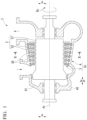
- the steam turbine 1 includes a rotor 2 and a turbine stator 10.
- the rotor 2 is rotatable around an axis Ar.
- the rotor 2 has a rotor shaft 21 extending in an axial direction Da around the axis Ar, and a plurality of rotor blades 22 fixed to the rotor shaft 21 along a circumferential direction Dc with respect to the rotor shaft 21.
- the direction in which the axis Ar extends is referred to as the axial direction Da.
- the radial direction with respect to the axis Ar as a reference is simply referred to as a radial direction Dr.
- the vertical direction of the paper surface in Fig. 1 is defined as a vertical direction Dv.
- the right and left direction of Fig. 1 and the right and left direction of Fig. 4 are defined as a horizontal direction Dh orthogonal to the vertical direction Dv.
- the direction around the rotor 2 centered on the axis Ar is defined as the circumferential direction Dc.
- the turbine stator 10 accommodates the rotor 2 inside in a state of being rotatable centered on the axis Ar.
- the turbine stator 10 has a partition plate 3 and a casing 4.
- the partition plate 3 is disposed on the outer circumferential side of the rotor 2.
- the partition plate 3 has an annular shape centered on the axis Ar.
- the partition plate 3 that has an annular shape has a plurality of nozzles (stator blades) 8 arranged in the circumferential direction Dc at a position near the middle of the partition plate 3 in the radial direction Dr and on the upstream side in the axial direction Da from the rotor blade 22 of the rotor 2.
- a cylindrical space on the outer circumferential side of the rotor shaft 21 and near the middle of the partition plate 3 that has an annular shape, that is, the space where the rotor blade 22 and a nozzle 8 are disposed is a steam flow path through which steam of working fluid flows.
- the details of the shape of the partition plate 3 will be described below.
- the casing 4 is disposed on the outer circumferential side of the partition plate 3.
- the casing 4 has a cylindrical shape centered on the axis Ar.
- the casing 4 surrounds the partition plate 3 from the outer side in the radial direction Dr.
- the casing 4 that has a cylindrical shape includes an upper half casing 41 on the upper portion and a lower half casing 42 on the lower portion with the axis Ar of the rotor 2 as a reference.
- the upper half casing 41 extends in the circumferential direction Dc.
- the cross section of the upper half casing 41 orthogonal to the axis Ar forms a semi-annular shape centered on the axis Ar.
- the upper half casing 41 opens to face a lower side in the vertical direction Dv so as to be capable of accommodating the rotor 2 and the partition plate 3.
- the lower half casing 42 extends in the circumferential direction Dc.
- the cross section of the lower half casing 42 orthogonal to the axis Ar forms a semi-annular shape centered on the axis Ar.
- An inner diameter of the lower half casing 42 is formed to be the same as an inner diameter of the upper half casing 41.
- the lower half casing 42 opens to face the upper side in the vertical direction Dv so as to be capable of accommodating the rotor 2 and the partition plate 3.
- the upper half casing 41 is placed on the lower half casing 42 on the upper side in the vertical direction Dv and is fixed by a fastening member such as a bolt 331 (not shown) in a state where the dividing surfaces are in contact with each other. As a result, the casing 4 is formed.
- the partition plate 3 has an inner ring 6, an outer ring 7, the nozzle 8, and an annular protruding portion 9.
- the inner ring 6, the outer ring 7, the nozzle 8, and the annular protruding portion 9 are integrally formed or welded and joined to form a single member.
- the inner ring 6 extends in the circumferential direction Dc around axis Ar.
- the nozzle 8 is fixed to an inner ring outer circumferential surface 61, which is a surface (outer circumferential surface) of the inner ring 6 facing the outer side in the radial direction Dr.
- an inner ring nozzle fixing groove 62 into which part of the nozzle 8 is fitted is formed on the inner ring outer circumferential surface 61.
- the inner ring nozzle fixing groove 62 is a groove formed so as to be recessed to the inner side in the radial direction Dr from the inner ring outer circumferential surface 61.
- the outer ring 7 is provided on the outer side of the inner ring 6 in the radial direction Dr such that the nozzle 8 is interposed.
- the outer ring 7 extends in the circumferential direction Dc centered on the axis Ar.
- the nozzle 8 is fixed to an outer ring inner circumferential surface 71, which is a surface (inner circumferential surface) of the outer ring 7 facing the inner side in the radial direction Dr.
- an outer ring nozzle fixing groove 72 into which part of the nozzle 8 is fitted is formed on the outer ring inner circumferential surface 71.
- the outer ring nozzle fixing groove 72 is a groove formed so as to be recessed to the outer side in the radial direction Dr from the outer ring inner circumferential surface 71.
- the nozzle 8 is capable of guiding the fluid toward the rotor blade 22 from the upstream side to the downstream side in the axial direction Da.
- a plurality of the nozzles 8 are provided in the circumferential direction Dc in a state of being interposed between the inner ring 6 and the outer ring 7 in the radial direction Dr.
- the nozzle 8 according to the present embodiment has an inner shroud ring 81, a blade 82, and an outer shroud ring 83.
- the inner shroud ring 81 fixes the blade 82 to the inner ring 6.
- An inner protrusion 811 that fits into the inner ring nozzle fixing groove 62 is formed on the surface (inner circumferential surface) of the inner shroud ring 81 facing the inner side in the radial direction Dr.
- a welding portion 50 is formed by performing welding between the inner shroud ring 81 and the inner ring 6 and is integrally joined.
- the outer shroud ring 83 fixes the blade 82 to the outer ring 7.
- the surface (inner circumferential surface) of the outer shroud ring 83 facing the inner side in the radial direction Dr is integrated with an end portion of the blade 82 on the outer side in the radial direction Dr.
- An outer protrusion 831 that fits into the outer ring nozzle fixing groove 72 is formed on the surface (outer circumferential surface) of the outer shroud ring 83 facing the outer side in the radial direction Dr.
- the welding portion 50 is formed by performing welding between the outer shroud ring 83 and the outer ring 7, and is integrally joined.
- the blade 82 extends between the inner shroud ring 81 and the outer shroud ring 83 in the radial direction Dr.
- the blade 82 is a member having a wing shape in cross-sectional shape as viewed from the radial direction Dr.
- the blade 82 and the rotor blade 22 described above are disposed at positions where the blade 82 and the rotor blade 22 overlap each other as viewed from the axial direction Da.
- a plurality of the blades 82 are disposed at intervals in the circumferential direction Dc.
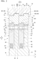
- the annular protruding portion 9 extends in the circumferential direction Dc along the outer ring 7. As shown in Fig. 2 , the annular protruding portion 9 protrudes from the outer ring 7 to the downstream side in the axial direction Da such that the position of the axial direction Da overlap the rotor blade 22 disposed on the downstream side of the nozzle 8 in a state where the partition plate 3 is accommodated in the casing 4.
- the annular protruding portion 9 is formed as an integral part with the outer ring 7.
- the annular protruding portion 9 protrudes to the outer side in the radial direction Dr from the outer ring outer circumferential surface 73 of the outer ring 7 in addition to the downstream side in the axial direction Da.
- the protruding portion inner circumferential surface 94 is a curved surface of the annular protruding portion 9 facing the inner side in the radial direction Dr.
- the end portion of the protruding portion inner circumferential surface 94 on the downstream side in the axial direction Da is connected to the inner side of the protruding portion downstream surface 93 in the radial direction Dr.
- the protruding portion inner circumferential surface 94 is formed at a position at a distance from the end surface formed at the tip of the rotor blade 22.
- a plurality of fins 941 are provided on the protruding portion inner circumferential surface 94.
- the fixing units 33 are provided at two locations separated from each other in the horizontal direction Dh.
- the fixing unit 33 provided on one side of the horizontal direction Dh on the right side of the paper surface in Fig. 4 will be described as an example.
- the fixing unit 33 on the other side of the horizontal direction Dh, for which description is omitted, also has the same configuration.
- the contact support surface 453 extends vertically from the inner circumferential surface of the casing 4.
- the contact support surface 453 connects the inner circumferential surface of the casing 4 and the end portion of the recess bottom surface 452 on the downstream side in the axial direction Da.
- the contact support surface 453 faces the recess separation surface 451.
- the contact support surface 453 is a plane parallel to the recess separation surface 451.
- the contact support surface 453 faces the protruding portion downstream surface 93.
- the contact support surface 453 is formed at a position being in contact with the protruding portion downstream surface 93 in a state where the partition plate 3 is accommodated in the casing 4. That is, the contact support surface 453 is in contact with the annular protruding portion 9 from the downstream side in the axial direction Da.
- the annular protruding portion 9 is formed integrally with the outer ring 7 and protrudes to the downstream side in the axial direction Da from the outer ring 7.
- the partition plate 3 has a shape in which the region on the outer side in the radial direction Dr protrudes to the downstream side in the axial direction Da from the region on the inner side in the radial direction Dr where the nozzle 8 or the inner ring 6 is disposed so as to have an arch shape when viewed from the radial direction Dr.
- the pressure with respect to the partition plate 3 on the downstream side in the axial direction Da is lower than the pressure on the upstream side.
- a load is generated on the partition plate 3 such that the region on the inner side in the radial direction Dr is curved toward the downstream side in the axial direction Da.
- the region on the outer side in the radial direction Dr protrudes to the downstream side in the axial direction Da.
- the partition plate 3 is supported by the casing 4 in a state where the protruding portion downstream surface 93 is in contact with the contact support surface 453. As a result, a compressive force acts on the region of the partition plate 3 on the inner side in the radial direction Dr.
- the annular protruding portion 9 protrudes to the outer side of the outer ring 7 in the radial direction Dr in addition to the axial direction Da. Therefore, in a case where the upper half casing 41 is assembled to the partition plate 3 accommodated in the lower half casing 42, the annular protruding portion 9 first contacts with the upper half casing 41 in the partition plate 3, and becomes a guide with respect to the upper half casing 41. As a result, the position of the annular protruding portion 9 with respect to the casing 4 can be determined with high accuracy. Accordingly, the annular protruding portion 9 can be reliably brought into contact with the contact support surface 453, and the deformation of the partition plate 3 can be suppressed with higher accuracy.
- the tapered surface 921 is formed on the corner formed by the protruding portion upstream surface 92 and the protruding portion outer circumferential surface 91. Therefore, in a case where the upper half casing 41 is assembled to the partition plate 3, it is possible to prevent the inner circumferential surface of the casing 4 from being placed on the corner and making it difficult for the annular protruding portion 9 to be inserted into the casing positioning recess 45. Therefore, the annular protruding portion 9 can be smoothly inserted into the casing positioning recess 45. As a result, it is possible to suppress the assemblability from being deteriorated such that the partition plate 3 and the casing 4 do not fit.
- annular protruding portion 9 also protrudes to the inner side of the outer ring 7 in the radial direction Dr. Further, the fins 941 that are sliding contact with the tip of the rotor blade 22 are provided on the protruding portion inner circumferential surface 94. Therefore, the annular protruding portion 9 itself can serve as a flow guide.
- the partition plate 3 has the vertically divided structure, it is possible to improve the assemblability of the partition plate 3.
- the upper half partition plate 31 and the lower half partition plate 32 are easily deformed so as to be open between the upper half partition plate dividing surface 311 and the lower half partition plate dividing surface 321.
- the bolt fixing unit 333 is formed at a position closer to the outer circumferential surface of the outer shroud ring 83 than the protruding portion outer circumferential surface 91 in the radial direction Dr. Therefore, the upper half partition plate 31 and the lower half partition plate 32 are fixed at positions close to the nozzle 8.
Landscapes
- Engineering & Computer Science (AREA)
- Mechanical Engineering (AREA)
- General Engineering & Computer Science (AREA)
- Turbine Rotor Nozzle Sealing (AREA)
Claims (4)
- Turbinenstator (10) einer Dampfturbine (1), umfassend:eine Trennplatte (3) mit einem Innenring (6), der sich entlang einer Umfangsrichtung um eine Achse (Ar) erstreckt, einem Außenring (7), der in einer radialen Richtung in Bezug auf die Achse an einer Außenseite in Bezug auf den Innenring (6) angeordnet ist und sich in der Umfangsrichtung erstreckt, einer Vielzahl von Düsen (8), die zwischen dem Innenring (6) und dem Außenring (7) in der Umfangsrichtung angeordnet sind und so eingerichtet sind, dass sie ein Fluid von einer stromaufwärtigen Seite zu einer stromabwärtigen Seite in einer axialen Richtung führen, in der sich die Achse erstreckt, und einem ringförmigen vorstehenden Abschnitt (9), der von dem Außenring (7) nur zu der stromabwärtigen Seite in der axialen Richtung vorsteht, so dass er eine Position der Düsen (8) in der axialen Richtung nicht überlappt, und sich entlang des Außenrings (7) in der Umfangsrichtung erstreckt, undein Gehäuse (4), das die Trennplatte (3) von der Außenseite in der radialen Richtung umgibt, und eine Kontaktstützfläche (453) aufweist, die mit dem ringförmigen vorstehenden Abschnitt (9) von der stromabwärtigen Seite in axialer Richtung in Kontakt steht,wobei die Trennplatte (3) umfasst:eine obere Trennplattenhälfte (31) mit einer halbringförmigen Form und obere Trennplattenhälften-Teilungsflächen (311), die horizontale Flächen sind, die einer unteren Seite in vertikaler Richtung an beiden Enden in Umfangsrichtung zugewandt sind,eine untere Trennplattenhälfte (32) mit einer halbringförmigen Form und unteren Trennplattenhälften-Teilungsflächen (321), die so eingerichtet sind, dass sie an beiden Enden in Umfangsrichtung mit den oberen Trennplattenhälften-Teilungsflächen (311) in Kontakt stehen, unddadurch gekennzeichnet, dass die Trennplatte (3) ferner umfasst:eine Befestigungseinheit (33), welche die obere Trennplattenhälfte (31) und die untere Trennplattenhälfte (32) so befestigt, dass sie in einer Position, die in radialer Richtung näher an der Düse liegt als die Außenumfangsfläche des Außenrings (7) und/oder die Außenumfangsfläche des ringförmigen vorstehenden Abschnitts (9), unbeweglich sind,wobei die Befestigungseinheit (33) den ringförmigen vorstehenden Abschnitt (9) der oberen Trennplattenhälfte (31) und den ringförmigen vorstehenden Abschnitt (9) der unteren Trennplattenhälfte (32) unbeweglich befestigt,die Befestigungseinheit (33) einen Bolzen (331), ein Bolzeneinführloch (332b), das in dem ringförmigen vorstehenden Abschnitt (9) der oberen Trennplattenhälfte (31) ausgebildet ist, und eine Bolzenbefestigungseinheit (333), die in dem ringförmigen vorstehenden Abschnitt (9) der unteren Trennplattenhälfte (32) ausgebildet ist, aufweist,das Bolzeneinführloch (332b) den ringförmigen vorstehenden Abschnitt der oberen Trennplattenhälfte (31) durchdringt und in das ein Schraubabschnitt des Bolzens (331) eingeführt wird,die Bolzenbefestigungseinheit (333) ein Schraubenloch ist, das von der unteren Trennplattenhälften-Teilungsfläche (321) ausgespart ist, undder Bolzen (331) in der Bolzenbefestigungseinheit (333) durch Einsetzen eines Schraubenteils des Bolzens (331) befestigt wird,wobei der ringförmige vorstehende Abschnitt aufweist:eine Außenumfangsfläche (91) des vorstehenden Abschnitts, die auf der Außenseite in der radialen Richtung (Dr) von einer Außenumfangsfläche des Außenrings gebildet wird und in radialer Richtung (Dr) der Außenseite zugewandt ist,eine stromaufwärtige Fläche (92) des vorstehenden Abschnitts, die auf der Außenseite in der radialen Richtung von der Außenumfangsfläche des Außenrings gebildet wird und in axialer Richtung der stromaufwärtigen Seite zugewandt ist,eine abgeschrägte Fläche (921), die an einer Ecke ausgebildet ist, die durch die Außenumfangsfläche des vorstehenden Abschnitts und die stromaufwärtige Fläche des vorstehenden Abschnitts gebildet wird,eine stromabwärtige Fläche (93) des vorstehenden Abschnitts, die mit einem Endabschnitt der Außenumfangsfläche des vorstehenden Abschnitts auf der stromabwärtigen Seite in axialer Richtung verbunden ist und in axialer Richtung der stromabwärtigen Seite zugewandt ist, undeine Innenumfangsfläche (94) des vorstehenden Abschnitts, die mit einem Endabschnitt der stromabwärtigen Fläche des vorstehenden Abschnitts in der radialen Richtung verbunden ist und in radialer Richtung der Innenseite zugewandt ist.
- Turbinenstator (10) der Dampfturbine (1) nach Anspruch 1, wobei der ringförmige vorstehende Abschnitt (9) in radialer Richtung von einer Außenumfangsfläche des Außenrings (7), die in radialer Richtung der Außenseite zugewandt ist, zur Außenseite vorsteht.
- Turbinenstator (10) der Dampfturbine (1) nach Anspruch 1 oder 2, wobei eine Rippe auf einer Fläche des ringförmigen vorstehenden Abschnitts (9) angeordnet ist, die in radialer Richtung einer Innenseite zugewandt ist.
- Dampfturbine (1), umfassend:
den Turbinenstator (10) nach einem der Ansprüche 1 bis 3; und einen Rotor (2), der so eingerichtet ist, dass er sich um die Achse im Turbinenstator (10) dreht.
Applications Claiming Priority (2)
| Application Number | Priority Date | Filing Date | Title |
|---|---|---|---|
| JP2018183138A JP7051656B2 (ja) | 2018-09-28 | 2018-09-28 | タービンステータ、蒸気タービン、及び仕切板 |
| PCT/JP2019/038344 WO2020067496A1 (ja) | 2018-09-28 | 2019-09-27 | タービンステータ、蒸気タービン、及び仕切板 |
Publications (3)
| Publication Number | Publication Date |
|---|---|
| EP3835552A1 EP3835552A1 (de) | 2021-06-16 |
| EP3835552A4 EP3835552A4 (de) | 2021-08-25 |
| EP3835552B1 true EP3835552B1 (de) | 2025-07-09 |
Family
ID=69950154
Family Applications (1)
| Application Number | Title | Priority Date | Filing Date |
|---|---|---|---|
| EP19867806.2A Active EP3835552B1 (de) | 2018-09-28 | 2019-09-27 | Turbinenstator einer dampfturbine und entsprechende dampfturbine |
Country Status (5)
| Country | Link |
|---|---|
| US (1) | US11655733B2 (de) |
| EP (1) | EP3835552B1 (de) |
| JP (1) | JP7051656B2 (de) |
| CN (1) | CN112771248B (de) |
| WO (1) | WO2020067496A1 (de) |
Families Citing this family (2)
| Publication number | Priority date | Publication date | Assignee | Title |
|---|---|---|---|---|
| CN114704338B (zh) * | 2022-03-09 | 2023-12-08 | 中国船舶重工集团公司第七0三研究所 | 一种汽轮机动静部件的垂直装配定位结构 |
| JP7793828B1 (ja) * | 2025-03-03 | 2026-01-05 | 株式会社東芝 | シールフィンの固定方法 |
Citations (3)
| Publication number | Priority date | Publication date | Assignee | Title |
|---|---|---|---|---|
| US8105023B2 (en) * | 2007-01-09 | 2012-01-31 | Kabushiki Kaisha Toshiba | Steam turbine |
| EP2657454B1 (de) * | 2012-04-26 | 2014-05-14 | Alstom Technology Ltd | Turbinenschaufelträgeraufbau |
| US20170096904A1 (en) * | 2012-09-13 | 2017-04-06 | General Electric Company | Rotary machine and nozzle assembly therefor |
Family Cites Families (19)
| Publication number | Priority date | Publication date | Assignee | Title |
|---|---|---|---|---|
| US2197521A (en) * | 1938-04-21 | 1940-04-16 | Westinghouse Electric & Mfg Co | Turbine apparatus |
| JPH10331604A (ja) * | 1997-05-30 | 1998-12-15 | Toshiba Corp | 蒸気タービンプラント |
| JP4040922B2 (ja) * | 2001-07-19 | 2008-01-30 | 株式会社東芝 | 組立式ノズルダイアフラムおよびその組立方法 |
| GB0319002D0 (en) * | 2003-05-13 | 2003-09-17 | Alstom Switzerland Ltd | Improvements in or relating to steam turbines |
| US7287956B2 (en) * | 2004-12-22 | 2007-10-30 | General Electric Company | Removable abradable seal carriers for sealing between rotary and stationary turbine components |
| US7713024B2 (en) * | 2007-02-09 | 2010-05-11 | General Electric Company | Bling nozzle/carrier interface design for a steam turbine |
| JP5342579B2 (ja) | 2011-02-28 | 2013-11-13 | 三菱重工業株式会社 | 回転機械の静翼ユニット、回転機械の静翼ユニットの製造方法及び回転機械の静翼ユニットの結合方法 |
| JP5665724B2 (ja) * | 2011-12-12 | 2015-02-04 | 株式会社東芝 | 静翼翼列、静翼翼列の組立方法および蒸気タービン |
| JP2013177866A (ja) * | 2012-02-29 | 2013-09-09 | Hitachi Ltd | ターボ機械 |
| ES2984405T3 (es) | 2012-09-13 | 2024-10-29 | Bristol Myers Squibb Co | Proteínas de dominio de andamio basadas en fibronectina que se unen a la miostatina |
| JP6010488B2 (ja) | 2013-03-11 | 2016-10-19 | 株式会社東芝 | 軸流タービンおよびこれを備えた発電プラント |
| JP6434780B2 (ja) * | 2014-11-12 | 2018-12-05 | 三菱日立パワーシステムズ株式会社 | タービン用ロータアセンブリ、タービン、及び、動翼 |
| JP2016114131A (ja) * | 2014-12-12 | 2016-06-23 | 三菱日立パワーシステムズ株式会社 | シール装置、回転機械、及びシール装置の製造方法 |
| US20170350264A1 (en) * | 2014-12-24 | 2017-12-07 | Mitsubishi Heavy Industries Compressor Corporation | Nozzle structure and rotary machine |
| JP6546053B2 (ja) * | 2015-09-18 | 2019-07-17 | 株式会社東芝 | 組立式ノズルダイヤフラム及び蒸気タービン |
| JP2017115803A (ja) * | 2015-12-25 | 2017-06-29 | 株式会社東芝 | ノズルダイアフラム、タービンロータ及び蒸気タービン |
| JP2017150386A (ja) | 2016-02-24 | 2017-08-31 | 株式会社東芝 | ノズルダイアフラムおよび蒸気タービン |
| PL3284919T3 (pl) * | 2016-08-16 | 2024-12-09 | General Electric Technology Gmbh | Turbina o przepływie osiowym mająca kryzę podzieloną na dwie połowy w płaszczyźnie połączenia |
| CN206343056U (zh) * | 2016-12-08 | 2017-07-21 | 广东佳德环保科技有限公司 | 一种高效率脱除气溶胶的水洗装置 |
-
2018
- 2018-09-28 JP JP2018183138A patent/JP7051656B2/ja active Active
-
2019
- 2019-09-27 EP EP19867806.2A patent/EP3835552B1/de active Active
- 2019-09-27 US US17/274,681 patent/US11655733B2/en active Active
- 2019-09-27 WO PCT/JP2019/038344 patent/WO2020067496A1/ja not_active Ceased
- 2019-09-27 CN CN201980063045.4A patent/CN112771248B/zh active Active
Patent Citations (3)
| Publication number | Priority date | Publication date | Assignee | Title |
|---|---|---|---|---|
| US8105023B2 (en) * | 2007-01-09 | 2012-01-31 | Kabushiki Kaisha Toshiba | Steam turbine |
| EP2657454B1 (de) * | 2012-04-26 | 2014-05-14 | Alstom Technology Ltd | Turbinenschaufelträgeraufbau |
| US20170096904A1 (en) * | 2012-09-13 | 2017-04-06 | General Electric Company | Rotary machine and nozzle assembly therefor |
Also Published As
| Publication number | Publication date |
|---|---|
| WO2020067496A1 (ja) | 2020-04-02 |
| JP2020051373A (ja) | 2020-04-02 |
| EP3835552A1 (de) | 2021-06-16 |
| JP7051656B2 (ja) | 2022-04-11 |
| CN112771248B (zh) | 2024-01-09 |
| US20220049627A1 (en) | 2022-02-17 |
| US11655733B2 (en) | 2023-05-23 |
| EP3835552A4 (de) | 2021-08-25 |
| CN112771248A (zh) | 2021-05-07 |
Similar Documents
| Publication | Publication Date | Title |
|---|---|---|
| KR101843299B1 (ko) | 시일 구조 및 회전 기계 | |
| KR101516102B1 (ko) | 축 시일 장치 및 이것을 구비하는 회전 기계 | |
| EP3835552B1 (de) | Turbinenstator einer dampfturbine und entsprechende dampfturbine | |
| US20190277139A1 (en) | Steam turbine apparatus | |
| JP5509012B2 (ja) | 蒸気タービン | |
| KR102214736B1 (ko) | 정익 세그먼트, 및 이를 구비하고 있는 증기 터빈 | |
| WO2017142077A1 (ja) | 回転機械 | |
| JP2016084861A (ja) | ラビリンスシール装置および軸流型ターボ機械 | |
| EP3032149A1 (de) | Abdichtungsvorrichtung, drehmaschine und verfahren zur herstellung der abdichtungsvorrichtung | |
| JP2015140685A (ja) | 蒸気タービンを含む熱機関の流体シール構造 | |
| EP3232010B1 (de) | Leitschaufel und drehmaschine | |
| CN105324554B (zh) | 轴流膨胀机 | |
| EP2860357A1 (de) | Dampfturbinendichtungsvorrichtung | |
| US12044131B2 (en) | Labyrinth seal and gas turbine | |
| US20250035006A1 (en) | Sealing device and rotating machine | |
| JP2012112359A (ja) | 軸流排気タービンの軸受台カバーおよび軸流排気タービン | |
| US12215789B2 (en) | Labyrinth seal and gas turbine | |
| US10697468B2 (en) | Casing assembly and rotary machine | |
| CN118602016B (zh) | 旋转机械、空气轴承及其顶箔 | |
| EP3220018B1 (de) | Wellendichtungsmechanismus | |
| JP6076888B2 (ja) | タービンロータ組立体およびそれを備えたタービン | |
| JP5657268B2 (ja) | 軸シール装置 |
Legal Events
| Date | Code | Title | Description |
|---|---|---|---|
| STAA | Information on the status of an ep patent application or granted ep patent |
Free format text: STATUS: THE INTERNATIONAL PUBLICATION HAS BEEN MADE |
|
| PUAI | Public reference made under article 153(3) epc to a published international application that has entered the european phase |
Free format text: ORIGINAL CODE: 0009012 |
|
| STAA | Information on the status of an ep patent application or granted ep patent |
Free format text: STATUS: REQUEST FOR EXAMINATION WAS MADE |
|
| 17P | Request for examination filed |
Effective date: 20210311 |
|
| AK | Designated contracting states |
Kind code of ref document: A1 Designated state(s): AL AT BE BG CH CY CZ DE DK EE ES FI FR GB GR HR HU IE IS IT LI LT LU LV MC MK MT NL NO PL PT RO RS SE SI SK SM TR |
|
| A4 | Supplementary search report drawn up and despatched |
Effective date: 20210726 |
|
| RIC1 | Information provided on ipc code assigned before grant |
Ipc: F01D 9/04 20060101AFI20210720BHEP Ipc: F01D 25/24 20060101ALI20210720BHEP |
|
| DAV | Request for validation of the european patent (deleted) | ||
| DAX | Request for extension of the european patent (deleted) | ||
| STAA | Information on the status of an ep patent application or granted ep patent |
Free format text: STATUS: EXAMINATION IS IN PROGRESS |
|
| 17Q | First examination report despatched |
Effective date: 20230203 |
|
| GRAP | Despatch of communication of intention to grant a patent |
Free format text: ORIGINAL CODE: EPIDOSNIGR1 |
|
| STAA | Information on the status of an ep patent application or granted ep patent |
Free format text: STATUS: GRANT OF PATENT IS INTENDED |
|
| INTG | Intention to grant announced |
Effective date: 20250207 |
|
| GRAS | Grant fee paid |
Free format text: ORIGINAL CODE: EPIDOSNIGR3 |
|
| GRAA | (expected) grant |
Free format text: ORIGINAL CODE: 0009210 |
|
| STAA | Information on the status of an ep patent application or granted ep patent |
Free format text: STATUS: THE PATENT HAS BEEN GRANTED |
|
| RAP3 | Party data changed (applicant data changed or rights of an application transferred) |
Owner name: MITSUBISHI HEAVY INDUSTRIES COMPRESSOR CORPORATION |
|
| AK | Designated contracting states |
Kind code of ref document: B1 Designated state(s): AL AT BE BG CH CY CZ DE DK EE ES FI FR GB GR HR HU IE IS IT LI LT LU LV MC MK MT NL NO PL PT RO RS SE SI SK SM TR |
|
| REG | Reference to a national code |
Ref country code: GB Ref legal event code: FG4D |
|
| REG | Reference to a national code |
Ref country code: CH Ref legal event code: EP |
|
| REG | Reference to a national code |
Ref country code: IE Ref legal event code: FG4D |
|
| REG | Reference to a national code |
Ref country code: DE Ref legal event code: R096 Ref document number: 602019072428 Country of ref document: DE |
|
| PGFP | Annual fee paid to national office [announced via postgrant information from national office to epo] |
Ref country code: DE Payment date: 20250926 Year of fee payment: 7 |
|
| PGFP | Annual fee paid to national office [announced via postgrant information from national office to epo] |
Ref country code: IT Payment date: 20250911 Year of fee payment: 7 |
|
| REG | Reference to a national code |
Ref country code: NL Ref legal event code: MP Effective date: 20250709 |
|
| PG25 | Lapsed in a contracting state [announced via postgrant information from national office to epo] |
Ref country code: PT Free format text: LAPSE BECAUSE OF FAILURE TO SUBMIT A TRANSLATION OF THE DESCRIPTION OR TO PAY THE FEE WITHIN THE PRESCRIBED TIME-LIMIT Effective date: 20251110 |
|
| PG25 | Lapsed in a contracting state [announced via postgrant information from national office to epo] |
Ref country code: NL Free format text: LAPSE BECAUSE OF FAILURE TO SUBMIT A TRANSLATION OF THE DESCRIPTION OR TO PAY THE FEE WITHIN THE PRESCRIBED TIME-LIMIT Effective date: 20250709 |
|
| REG | Reference to a national code |
Ref country code: AT Ref legal event code: MK05 Ref document number: 1812002 Country of ref document: AT Kind code of ref document: T Effective date: 20250709 |
|
| PG25 | Lapsed in a contracting state [announced via postgrant information from national office to epo] |
Ref country code: IS Free format text: LAPSE BECAUSE OF FAILURE TO SUBMIT A TRANSLATION OF THE DESCRIPTION OR TO PAY THE FEE WITHIN THE PRESCRIBED TIME-LIMIT Effective date: 20251109 |
|
| PG25 | Lapsed in a contracting state [announced via postgrant information from national office to epo] |
Ref country code: NO Free format text: LAPSE BECAUSE OF FAILURE TO SUBMIT A TRANSLATION OF THE DESCRIPTION OR TO PAY THE FEE WITHIN THE PRESCRIBED TIME-LIMIT Effective date: 20251009 |
|
| REG | Reference to a national code |
Ref country code: LT Ref legal event code: MG9D |
|
| PG25 | Lapsed in a contracting state [announced via postgrant information from national office to epo] |
Ref country code: AT Free format text: LAPSE BECAUSE OF FAILURE TO SUBMIT A TRANSLATION OF THE DESCRIPTION OR TO PAY THE FEE WITHIN THE PRESCRIBED TIME-LIMIT Effective date: 20250709 |
|
| PG25 | Lapsed in a contracting state [announced via postgrant information from national office to epo] |
Ref country code: FI Free format text: LAPSE BECAUSE OF FAILURE TO SUBMIT A TRANSLATION OF THE DESCRIPTION OR TO PAY THE FEE WITHIN THE PRESCRIBED TIME-LIMIT Effective date: 20250709 |
|
| PG25 | Lapsed in a contracting state [announced via postgrant information from national office to epo] |
Ref country code: HR Free format text: LAPSE BECAUSE OF FAILURE TO SUBMIT A TRANSLATION OF THE DESCRIPTION OR TO PAY THE FEE WITHIN THE PRESCRIBED TIME-LIMIT Effective date: 20250709 |
|
| PG25 | Lapsed in a contracting state [announced via postgrant information from national office to epo] |
Ref country code: GR Free format text: LAPSE BECAUSE OF FAILURE TO SUBMIT A TRANSLATION OF THE DESCRIPTION OR TO PAY THE FEE WITHIN THE PRESCRIBED TIME-LIMIT Effective date: 20251010 |
|
| PG25 | Lapsed in a contracting state [announced via postgrant information from national office to epo] |
Ref country code: SE Free format text: LAPSE BECAUSE OF FAILURE TO SUBMIT A TRANSLATION OF THE DESCRIPTION OR TO PAY THE FEE WITHIN THE PRESCRIBED TIME-LIMIT Effective date: 20250709 |
|
| PG25 | Lapsed in a contracting state [announced via postgrant information from national office to epo] |
Ref country code: LV Free format text: LAPSE BECAUSE OF FAILURE TO SUBMIT A TRANSLATION OF THE DESCRIPTION OR TO PAY THE FEE WITHIN THE PRESCRIBED TIME-LIMIT Effective date: 20250709 |
|
| PG25 | Lapsed in a contracting state [announced via postgrant information from national office to epo] |
Ref country code: BG Free format text: LAPSE BECAUSE OF FAILURE TO SUBMIT A TRANSLATION OF THE DESCRIPTION OR TO PAY THE FEE WITHIN THE PRESCRIBED TIME-LIMIT Effective date: 20250709 Ref country code: PL Free format text: LAPSE BECAUSE OF FAILURE TO SUBMIT A TRANSLATION OF THE DESCRIPTION OR TO PAY THE FEE WITHIN THE PRESCRIBED TIME-LIMIT Effective date: 20250709 |
|
| PG25 | Lapsed in a contracting state [announced via postgrant information from national office to epo] |
Ref country code: RS Free format text: LAPSE BECAUSE OF FAILURE TO SUBMIT A TRANSLATION OF THE DESCRIPTION OR TO PAY THE FEE WITHIN THE PRESCRIBED TIME-LIMIT Effective date: 20251009 |
|
| PG25 | Lapsed in a contracting state [announced via postgrant information from national office to epo] |
Ref country code: ES Free format text: LAPSE BECAUSE OF FAILURE TO SUBMIT A TRANSLATION OF THE DESCRIPTION OR TO PAY THE FEE WITHIN THE PRESCRIBED TIME-LIMIT Effective date: 20250709 |
|
| PG25 | Lapsed in a contracting state [announced via postgrant information from national office to epo] |
Ref country code: RO Free format text: LAPSE BECAUSE OF FAILURE TO SUBMIT A TRANSLATION OF THE DESCRIPTION OR TO PAY THE FEE WITHIN THE PRESCRIBED TIME-LIMIT Effective date: 20250709 |
|
| PG25 | Lapsed in a contracting state [announced via postgrant information from national office to epo] |
Ref country code: SM Free format text: LAPSE BECAUSE OF FAILURE TO SUBMIT A TRANSLATION OF THE DESCRIPTION OR TO PAY THE FEE WITHIN THE PRESCRIBED TIME-LIMIT Effective date: 20250709 |
|
| PG25 | Lapsed in a contracting state [announced via postgrant information from national office to epo] |
Ref country code: DK Free format text: LAPSE BECAUSE OF FAILURE TO SUBMIT A TRANSLATION OF THE DESCRIPTION OR TO PAY THE FEE WITHIN THE PRESCRIBED TIME-LIMIT Effective date: 20250709 |
|
| PG25 | Lapsed in a contracting state [announced via postgrant information from national office to epo] |
Ref country code: CZ Free format text: LAPSE BECAUSE OF FAILURE TO SUBMIT A TRANSLATION OF THE DESCRIPTION OR TO PAY THE FEE WITHIN THE PRESCRIBED TIME-LIMIT Effective date: 20250709 |
|
| PG25 | Lapsed in a contracting state [announced via postgrant information from national office to epo] |
Ref country code: SK Free format text: LAPSE BECAUSE OF FAILURE TO SUBMIT A TRANSLATION OF THE DESCRIPTION OR TO PAY THE FEE WITHIN THE PRESCRIBED TIME-LIMIT Effective date: 20250709 Ref country code: EE Free format text: LAPSE BECAUSE OF FAILURE TO SUBMIT A TRANSLATION OF THE DESCRIPTION OR TO PAY THE FEE WITHIN THE PRESCRIBED TIME-LIMIT Effective date: 20250709 |