EP3831432B1 - Respiratory care system with electronic indicator - Google Patents
Respiratory care system with electronic indicator Download PDFInfo
- Publication number
- EP3831432B1 EP3831432B1 EP21153010.0A EP21153010A EP3831432B1 EP 3831432 B1 EP3831432 B1 EP 3831432B1 EP 21153010 A EP21153010 A EP 21153010A EP 3831432 B1 EP3831432 B1 EP 3831432B1
- Authority
- EP
- European Patent Office
- Prior art keywords
- indicator
- flow indicator
- flow
- inhalation
- electronic
- Prior art date
- Legal status (The legal status is an assumption and is not a legal conclusion. Google has not performed a legal analysis and makes no representation as to the accuracy of the status listed.)
- Active
Links
Images


Classifications
-
- A—HUMAN NECESSITIES
- A61—MEDICAL OR VETERINARY SCIENCE; HYGIENE
- A61M—DEVICES FOR INTRODUCING MEDIA INTO, OR ONTO, THE BODY; DEVICES FOR TRANSDUCING BODY MEDIA OR FOR TAKING MEDIA FROM THE BODY; DEVICES FOR PRODUCING OR ENDING SLEEP OR STUPOR
- A61M11/00—Sprayers or atomisers specially adapted for therapeutic purposes
- A61M11/06—Sprayers or atomisers specially adapted for therapeutic purposes of the injector type
-
- A—HUMAN NECESSITIES
- A61—MEDICAL OR VETERINARY SCIENCE; HYGIENE
- A61M—DEVICES FOR INTRODUCING MEDIA INTO, OR ONTO, THE BODY; DEVICES FOR TRANSDUCING BODY MEDIA OR FOR TAKING MEDIA FROM THE BODY; DEVICES FOR PRODUCING OR ENDING SLEEP OR STUPOR
- A61M16/00—Devices for influencing the respiratory system of patients by gas treatment, e.g. ventilators; Tracheal tubes
- A61M16/20—Valves specially adapted to medical respiratory devices
- A61M16/201—Controlled valves
- A61M16/202—Controlled valves electrically actuated
-
- A—HUMAN NECESSITIES
- A61—MEDICAL OR VETERINARY SCIENCE; HYGIENE
- A61M—DEVICES FOR INTRODUCING MEDIA INTO, OR ONTO, THE BODY; DEVICES FOR TRANSDUCING BODY MEDIA OR FOR TAKING MEDIA FROM THE BODY; DEVICES FOR PRODUCING OR ENDING SLEEP OR STUPOR
- A61M15/00—Inhalators
- A61M15/0001—Details of inhalators; Constructional features thereof
- A61M15/0013—Details of inhalators; Constructional features thereof with inhalation check valves
- A61M15/0015—Details of inhalators; Constructional features thereof with inhalation check valves located upstream of the dispenser, i.e. not traversed by the product
-
- A—HUMAN NECESSITIES
- A61—MEDICAL OR VETERINARY SCIENCE; HYGIENE
- A61M—DEVICES FOR INTRODUCING MEDIA INTO, OR ONTO, THE BODY; DEVICES FOR TRANSDUCING BODY MEDIA OR FOR TAKING MEDIA FROM THE BODY; DEVICES FOR PRODUCING OR ENDING SLEEP OR STUPOR
- A61M15/00—Inhalators
- A61M15/0065—Inhalators with dosage or measuring devices
- A61M15/0068—Indicating or counting the number of dispensed doses or of remaining doses
- A61M15/008—Electronic counters
-
- A—HUMAN NECESSITIES
- A61—MEDICAL OR VETERINARY SCIENCE; HYGIENE
- A61M—DEVICES FOR INTRODUCING MEDIA INTO, OR ONTO, THE BODY; DEVICES FOR TRANSDUCING BODY MEDIA OR FOR TAKING MEDIA FROM THE BODY; DEVICES FOR PRODUCING OR ENDING SLEEP OR STUPOR
- A61M15/00—Inhalators
- A61M15/0086—Inhalation chambers
-
- A—HUMAN NECESSITIES
- A61—MEDICAL OR VETERINARY SCIENCE; HYGIENE
- A61M—DEVICES FOR INTRODUCING MEDIA INTO, OR ONTO, THE BODY; DEVICES FOR TRANSDUCING BODY MEDIA OR FOR TAKING MEDIA FROM THE BODY; DEVICES FOR PRODUCING OR ENDING SLEEP OR STUPOR
- A61M15/00—Inhalators
- A61M15/009—Inhalators using medicine packages with incorporated spraying means, e.g. aerosol cans
-
- A—HUMAN NECESSITIES
- A61—MEDICAL OR VETERINARY SCIENCE; HYGIENE
- A61M—DEVICES FOR INTRODUCING MEDIA INTO, OR ONTO, THE BODY; DEVICES FOR TRANSDUCING BODY MEDIA OR FOR TAKING MEDIA FROM THE BODY; DEVICES FOR PRODUCING OR ENDING SLEEP OR STUPOR
- A61M16/00—Devices for influencing the respiratory system of patients by gas treatment, e.g. ventilators; Tracheal tubes
- A61M16/06—Respiratory or anaesthetic masks
-
- A—HUMAN NECESSITIES
- A61—MEDICAL OR VETERINARY SCIENCE; HYGIENE
- A61M—DEVICES FOR INTRODUCING MEDIA INTO, OR ONTO, THE BODY; DEVICES FOR TRANSDUCING BODY MEDIA OR FOR TAKING MEDIA FROM THE BODY; DEVICES FOR PRODUCING OR ENDING SLEEP OR STUPOR
- A61M16/00—Devices for influencing the respiratory system of patients by gas treatment, e.g. ventilators; Tracheal tubes
- A61M16/10—Preparation of respiratory gases or vapours
- A61M16/14—Preparation of respiratory gases or vapours by mixing different fluids, one of them being in a liquid phase
- A61M16/16—Devices to humidify the respiration air
-
- A—HUMAN NECESSITIES
- A61—MEDICAL OR VETERINARY SCIENCE; HYGIENE
- A61M—DEVICES FOR INTRODUCING MEDIA INTO, OR ONTO, THE BODY; DEVICES FOR TRANSDUCING BODY MEDIA OR FOR TAKING MEDIA FROM THE BODY; DEVICES FOR PRODUCING OR ENDING SLEEP OR STUPOR
- A61M15/00—Inhalators
- A61M15/0001—Details of inhalators; Constructional features thereof
- A61M15/0021—Mouthpieces therefor
-
- A—HUMAN NECESSITIES
- A61—MEDICAL OR VETERINARY SCIENCE; HYGIENE
- A61M—DEVICES FOR INTRODUCING MEDIA INTO, OR ONTO, THE BODY; DEVICES FOR TRANSDUCING BODY MEDIA OR FOR TAKING MEDIA FROM THE BODY; DEVICES FOR PRODUCING OR ENDING SLEEP OR STUPOR
- A61M16/00—Devices for influencing the respiratory system of patients by gas treatment, e.g. ventilators; Tracheal tubes
- A61M16/0003—Accessories therefor, e.g. sensors, vibrators, negative pressure
- A61M2016/0015—Accessories therefor, e.g. sensors, vibrators, negative pressure inhalation detectors
- A61M2016/0018—Accessories therefor, e.g. sensors, vibrators, negative pressure inhalation detectors electrical
- A61M2016/0024—Accessories therefor, e.g. sensors, vibrators, negative pressure inhalation detectors electrical with an on-off output signal, e.g. from a switch
-
- A—HUMAN NECESSITIES
- A61—MEDICAL OR VETERINARY SCIENCE; HYGIENE
- A61M—DEVICES FOR INTRODUCING MEDIA INTO, OR ONTO, THE BODY; DEVICES FOR TRANSDUCING BODY MEDIA OR FOR TAKING MEDIA FROM THE BODY; DEVICES FOR PRODUCING OR ENDING SLEEP OR STUPOR
- A61M16/00—Devices for influencing the respiratory system of patients by gas treatment, e.g. ventilators; Tracheal tubes
- A61M16/0003—Accessories therefor, e.g. sensors, vibrators, negative pressure
- A61M2016/003—Accessories therefor, e.g. sensors, vibrators, negative pressure with a flowmeter
- A61M2016/0033—Accessories therefor, e.g. sensors, vibrators, negative pressure with a flowmeter electrical
- A61M2016/0036—Accessories therefor, e.g. sensors, vibrators, negative pressure with a flowmeter electrical in the breathing tube and used in both inspiratory and expiratory phase
-
- A—HUMAN NECESSITIES
- A61—MEDICAL OR VETERINARY SCIENCE; HYGIENE
- A61M—DEVICES FOR INTRODUCING MEDIA INTO, OR ONTO, THE BODY; DEVICES FOR TRANSDUCING BODY MEDIA OR FOR TAKING MEDIA FROM THE BODY; DEVICES FOR PRODUCING OR ENDING SLEEP OR STUPOR
- A61M2202/00—Special media to be introduced, removed or treated
- A61M2202/06—Solids
- A61M2202/064—Powder
-
- A—HUMAN NECESSITIES
- A61—MEDICAL OR VETERINARY SCIENCE; HYGIENE
- A61M—DEVICES FOR INTRODUCING MEDIA INTO, OR ONTO, THE BODY; DEVICES FOR TRANSDUCING BODY MEDIA OR FOR TAKING MEDIA FROM THE BODY; DEVICES FOR PRODUCING OR ENDING SLEEP OR STUPOR
- A61M2205/00—General characteristics of the apparatus
- A61M2205/33—Controlling, regulating or measuring
- A61M2205/3306—Optical measuring means
-
- A—HUMAN NECESSITIES
- A61—MEDICAL OR VETERINARY SCIENCE; HYGIENE
- A61M—DEVICES FOR INTRODUCING MEDIA INTO, OR ONTO, THE BODY; DEVICES FOR TRANSDUCING BODY MEDIA OR FOR TAKING MEDIA FROM THE BODY; DEVICES FOR PRODUCING OR ENDING SLEEP OR STUPOR
- A61M2205/00—General characteristics of the apparatus
- A61M2205/33—Controlling, regulating or measuring
- A61M2205/3317—Electromagnetic, inductive or dielectric measuring means
-
- A—HUMAN NECESSITIES
- A61—MEDICAL OR VETERINARY SCIENCE; HYGIENE
- A61M—DEVICES FOR INTRODUCING MEDIA INTO, OR ONTO, THE BODY; DEVICES FOR TRANSDUCING BODY MEDIA OR FOR TAKING MEDIA FROM THE BODY; DEVICES FOR PRODUCING OR ENDING SLEEP OR STUPOR
- A61M2205/00—General characteristics of the apparatus
- A61M2205/33—Controlling, regulating or measuring
- A61M2205/332—Force measuring means
-
- A—HUMAN NECESSITIES
- A61—MEDICAL OR VETERINARY SCIENCE; HYGIENE
- A61M—DEVICES FOR INTRODUCING MEDIA INTO, OR ONTO, THE BODY; DEVICES FOR TRANSDUCING BODY MEDIA OR FOR TAKING MEDIA FROM THE BODY; DEVICES FOR PRODUCING OR ENDING SLEEP OR STUPOR
- A61M2205/00—General characteristics of the apparatus
- A61M2205/33—Controlling, regulating or measuring
- A61M2205/3331—Pressure; Flow
-
- A—HUMAN NECESSITIES
- A61—MEDICAL OR VETERINARY SCIENCE; HYGIENE
- A61M—DEVICES FOR INTRODUCING MEDIA INTO, OR ONTO, THE BODY; DEVICES FOR TRANSDUCING BODY MEDIA OR FOR TAKING MEDIA FROM THE BODY; DEVICES FOR PRODUCING OR ENDING SLEEP OR STUPOR
- A61M2205/00—General characteristics of the apparatus
- A61M2205/33—Controlling, regulating or measuring
- A61M2205/3375—Acoustical, e.g. ultrasonic, measuring means
-
- A—HUMAN NECESSITIES
- A61—MEDICAL OR VETERINARY SCIENCE; HYGIENE
- A61M—DEVICES FOR INTRODUCING MEDIA INTO, OR ONTO, THE BODY; DEVICES FOR TRANSDUCING BODY MEDIA OR FOR TAKING MEDIA FROM THE BODY; DEVICES FOR PRODUCING OR ENDING SLEEP OR STUPOR
- A61M2205/00—General characteristics of the apparatus
- A61M2205/35—Communication
- A61M2205/3546—Range
- A61M2205/3561—Range local, e.g. within room or hospital
-
- A—HUMAN NECESSITIES
- A61—MEDICAL OR VETERINARY SCIENCE; HYGIENE
- A61M—DEVICES FOR INTRODUCING MEDIA INTO, OR ONTO, THE BODY; DEVICES FOR TRANSDUCING BODY MEDIA OR FOR TAKING MEDIA FROM THE BODY; DEVICES FOR PRODUCING OR ENDING SLEEP OR STUPOR
- A61M2205/00—General characteristics of the apparatus
- A61M2205/35—Communication
- A61M2205/3576—Communication with non implanted data transmission devices, e.g. using external transmitter or receiver
- A61M2205/3592—Communication with non implanted data transmission devices, e.g. using external transmitter or receiver using telemetric means, e.g. radio or optical transmission
-
- A—HUMAN NECESSITIES
- A61—MEDICAL OR VETERINARY SCIENCE; HYGIENE
- A61M—DEVICES FOR INTRODUCING MEDIA INTO, OR ONTO, THE BODY; DEVICES FOR TRANSDUCING BODY MEDIA OR FOR TAKING MEDIA FROM THE BODY; DEVICES FOR PRODUCING OR ENDING SLEEP OR STUPOR
- A61M2205/00—General characteristics of the apparatus
- A61M2205/50—General characteristics of the apparatus with microprocessors or computers
- A61M2205/502—User interfaces, e.g. screens or keyboards
- A61M2205/505—Touch-screens; Virtual keyboard or keypads; Virtual buttons; Soft keys; Mouse touches
-
- A—HUMAN NECESSITIES
- A61—MEDICAL OR VETERINARY SCIENCE; HYGIENE
- A61M—DEVICES FOR INTRODUCING MEDIA INTO, OR ONTO, THE BODY; DEVICES FOR TRANSDUCING BODY MEDIA OR FOR TAKING MEDIA FROM THE BODY; DEVICES FOR PRODUCING OR ENDING SLEEP OR STUPOR
- A61M2205/00—General characteristics of the apparatus
- A61M2205/58—Means for facilitating use, e.g. by people with impaired vision
- A61M2205/583—Means for facilitating use, e.g. by people with impaired vision by visual feedback
- A61M2205/584—Means for facilitating use, e.g. by people with impaired vision by visual feedback having a color code
-
- A—HUMAN NECESSITIES
- A61—MEDICAL OR VETERINARY SCIENCE; HYGIENE
- A61M—DEVICES FOR INTRODUCING MEDIA INTO, OR ONTO, THE BODY; DEVICES FOR TRANSDUCING BODY MEDIA OR FOR TAKING MEDIA FROM THE BODY; DEVICES FOR PRODUCING OR ENDING SLEEP OR STUPOR
- A61M2205/00—General characteristics of the apparatus
- A61M2205/82—Internal energy supply devices
- A61M2205/8206—Internal energy supply devices battery-operated
-
- A—HUMAN NECESSITIES
- A61—MEDICAL OR VETERINARY SCIENCE; HYGIENE
- A61M—DEVICES FOR INTRODUCING MEDIA INTO, OR ONTO, THE BODY; DEVICES FOR TRANSDUCING BODY MEDIA OR FOR TAKING MEDIA FROM THE BODY; DEVICES FOR PRODUCING OR ENDING SLEEP OR STUPOR
- A61M2206/00—Characteristics of a physical parameter; associated device therefor
- A61M2206/10—Flow characteristics
- A61M2206/14—Static flow deviators in tubes disturbing laminar flow in tubes, e.g. archimedes screws
Definitions
- the present invention relates generally to a respiratory care system, and in particular, to a medicament delivery device, an accessory device to a medicament delivery device, or respiratory exercise device, each configured with an electronic indicator, which may provide visual, auditory or tactile feedback to a user or caregiver of inhalation, exhalation, and/or completion of a respiratory cycle, as well as end of life information for the system or device.
- nebulizer nebulizer
- DPI dry powder inhaler
- MDI metered dose inhaler
- Patients suffering from respiratory ailments may also benefit from using respiratory exercise devices, such as oscillating expiratory pressure devices.
- MDIs require the user to time their inhalation corresponding to actuation of the MDI, which may be difficult for some users, specifically children. Poor coordination may lead to medication being deposited in the mouth or throat rather than the lungs.
- an accessory device such as a valved holding chamber (VHC) may be used to suspend the medication dispensed from the MDI in the chamber until the user inhales. While a VHC aids in proper drug delivery from MDIs, the VHC may be enhanced by further indicating to the user that, for example, inhalation is successful. Such feedback may provide the user, whether a patient or caregiver, confidence that the patient is properly using the MDI and VHC and, thus, receiving the required medication.
- Electronic MDIs that provide feedback to a user or caregiver regarding the proper use of the MDI are known in the art. These MDls are typically quite expensive.
- While various devices may provide features that indicate to the user that inhalation and/or exhalation is being achieved, often the indicator is positioned within a chamber or other component housing, and may be difficult to observe due to humidity or moisture buildup during treatment. In addition, many devices are not able to provide an indication that a successful treatment was completed. For example, while information about flow is important, such indicators often do not provide information about whether all of the medication was properly delivered.
- Document US 2013 / 008 436 A1 relates to respiratory drug delivery apparatus including a medication storage and delivery device having an outlet and a feedback and compliance device coupled thereto.
- the feedback and compliance device has an opening, and the outlet of the medication storage and delivery device is received through the opening.
- the feedback and compliance device includes: (i) one or more sensors, each of the one or more sensors being structured to sense a parameter relating to use of the respiratory drug delivery apparatus without modifying or interfering with a flow of medication introduced by actuation of the medication storage and delivery device, (ii) one or more feedback devices, and (iii) a processing unit programmed to cause the one or more feedback devices to provide feedback information to a patient regarding use of the respiratory drug delivery apparatus based on an output of at least one of the one or more sensors.
- Document US 5 655 523 A relates to inhalation device for dry powder contain-ing a chamber capable of receiving a dose of powdered medicament.
- the chamber is in communication with a patient port in the form of a mouthpiece or nasal adapter.
- the inhalation device also contains a de-agglomeration/aerosolization apparatus capable of de-agglomerating and/or aerosolizing a dose of powdered medicament and is operable by a patient-independent energy output source.
- the inhalation device further includes detection apparatus that ascertains patient inspiration through the patient port, and a control apparatus that actuates the de-agglomeration/aerosolization apparatus in response to detection of patient inspiration.
- Document EP1338296 A1 relates to a flow indicator for an inhaler.
- the flow indicator comprises a housing defining a mouthpiece, an inlet for connection to the product-dispensing chamber of an inhaler, a chamber positioned between the inlet and the mouthpiece of the indicator, and an indicator member movably mounted in the chamber in such a manner that inhalation at the mouthpiece of the indicator causes the indicator member to move within the chamber, the indicator member being so mounted as to co-operate with a switch member associated with the housing to provide an indication when inhalation is at an optimum rate for a given inhaler attached to the inlet.
- the vane may carry a magnet and the switch member may be a magnetic reed switch, the magnet and the reed switch constituting a magnetic switch.
- the Figures show different embodiments of the medication delivery system, block/flow diagrams and methods for use and assembly thereof.
- FIG. 54 to 73 are not according to the present invention. The remaining Figures are part of the present invention.
- the term “plurality,” as used herein, means two or more.
- the term “coupled” means connected to or engaged with, whether directly or indirectly, for example with an intervening member, and does not require the engagement to be fixed or permanent, although it may be fixed or permanent.
- first,” “second,” “third,” etc., as used herein does not refer to any particular sequence or order of components; for example “first” and “second” ring-like housing components may refer to any sequence of such members, and is not limited to the first and second ring-like housing components of a particular configuration unless otherwise specified.
- “respiratory care system” includes any one or more of a medicament delivery device, an accessory device to a medicament delivery device, and respiratory exercise device.
- the various medicament delivery systems include a valved holding chamber 2 having an input end 12, an output end 14 having a user interface 16 with an outlet 18 and an interior volume 20 of space defined between the input and output ends.
- a flow indicator 22 is moveable in response to inhalation and/or exhalation by a user through the outlet.
- An electronic indicator 220 is operable in response to an electronic signal transmitted in response to the movement of the flow indicator 22.
- a housing 23 surrounds the flow indicator and defines a viewing window or port. The viewing port may be made translucent or transparent, such that the user may observe the movement of the flow indicator.
- the viewing window where the mechanical flow indicator 22 is located may be made opaque or obscured with a non-see through coating or color, such that the user is only able to observe the electronic indicator 220. In this latter embodiment, the user or caregiver would only see one indicator.
- Various respiratory care systems may include without limitation a valved holding chamber 2, a dry powder inhaler 4, a positive expiratory pressure device 6 or a nebulizer 8.
- a mechanical flow indicator 22 functions as an electrical switch as it moves between first and second positions during inhalation, for example as a flow path (P) is created along an inhalation path defined between the input and output ends 12, 14 of the holding chamber 2.
- An MDI includes a medicament canister 13 and an actuator boot 15, having a mouthpiece that is fitted within said input end 12, for example with a friction fit.
- the mechanical flow indicator 22 may be positioned outside of the inhalation path (P), but is responsive to flow along the flow path, for example by way of a negative pressure being created. It should be understood that the flow indicator may also be configured to move during exhalation.
- Various aspects of the flow indicator are shown for example and without limitation in U.S. Patent No. 8,550,067 for a "Visual Indicator for An Aerosol Medication Delivery Apparatus and System".
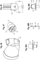
- the valved holding chamber 2 includes a front piece, or patient interface 16, having an adapter 24 or baffle section, otherwise referred to as a retainer, releasably secured to the end of the valved holding chamber, for example with tabs.
- a mouthpiece section 26 is coupled to the baffle section, for example with tabs 28 engaging openings 30.
- the adapter or baffle section includes an annular attachment collar 32 with slots 34, a transition piece 36 and a cylindrical exit port 38.
- the adapter is attached to the chamber by snap inserting tabs 40 on the chamber housing into the slots 34 and then twisting the chamber housing or adapter so that the tabs are locked into place within the slots.
- the baffle section 24 may alternatively be integrally formed as an end portion of the holding chamber.
- An inhalation valve 241 is seated on a front surface 42 of a baffle, which defines a valve seat.
- the inhalation valve is formed as an annular valve in one embodiment.
- the annular valve 241 has a central opening with an inner peripheral sealing edge 44 that seals against the valve seat 42.
- An outer peripheral edge 46 of the annular valve defines an exhalation valve that seats against a valve seat 48 defined by the mouthpiece.
- the inhalation valve may alternatively be formed as a duckbill valve, center post valve, slit petal valve and/or flap valve.
- the valve may be made of a soft plastic, such as silicone or a thermoplastic elastomer.
- the flow indicator 22 may be integrally attached to the inhalation valve, or separately formed as shown in FIG. 51 .
- the flow indicator is hingedly connected to the valve or a base 50, for example with living hinge formed at the junction thereof, or with a hinge pin.
- the base 50 may be secured to the valved holding chamber or the user interface.
- the resiliency of the flow indictor biases the indicator to an at rest position.
- the flow indicator provides a visual indicator to the user or caregiver that the user is inhaling.
- the flow indicator may be rectangular in shape, although other shapes, such as a square or an ellipse, may also be suitable.
- the visual flow indicator may have a rounded top edge as shown in FIGS. 23 and 51 .
- the mechanical flow indicator 22 is positioned in a housing 23 located at the input end of holding chamber 2.
- the flow indicator may be incorporated into a backpiece 230, secured to the input end of the chamber.
- the mechanical flow indicator 22 is configured to provide a range of electrical responses, rather than a simple normally open or closed switch.
- the flow indicator 22 is configured with, or incorporates, a flexible resistor. As the flow indicator 22 is deformed (e.g., bent) in greater amounts, as shown in FIGS. 66A-C , the resistance is varied, e.g., increased (or decreased).
- the resistor is incorporated into a circuit coupled to an electronic indicator, shown as an array of lights 1040, e.g., LED's, as further explained below.
- the flow indicator is positioned outside the flow path P, but ambient air is entrained through an opening in the housing 23, whether formed as a part of the back piece 230 or as part of the holding chamber 2.
- the air flow past the indicator 22 causes the flow indicator to bend a greater or lesser amount depending on the flow rate or volume.
- the resistance of the resistor in the circuit will cause a single light to illuminate, providing indicia that the system is ready, or there is no flow.
- the magnitude of the flow will rise to a predetermined desired flow rate, which causes the flow indicator 22 to bend, with the resistance being varied to signal the circuit to illuminate additional lights.
- a range of acceptable flow rates/volumes may be registered by the flow indicator bending between upper and lower limits, with the corresponding resistance change causing the circuit to illuminate between 2 and 3 additional lights for example. If the flow is too great, the flow indicator may bend beyond the acceptable range, causing an additional light (for example a different color, intensity or blinking) to illuminate and providing feedback that the flow rate is too great.
- This electronic indicator thereby provides feedback to the user and/or caregiver about the proper usage of the device.
- the array of lights may provide various indicia, such as change in colors (green to yellow to red) associated with acceptable, borderline and unacceptable flows.
- the circuit which may include a microprocessor, or may communicate with a remote computer or processor as further explained below in connection with FIGS. 69 and 70 , may also record the length or duration of the inhalation sequence, or the length or duration of the inhalation in the predetermined, acceptable flow range.
- the mechanical flow indicator 22 and electronic flow indicator 220 are housed at the input end of the valved holding chamber.
- a back piece 820 is configured with a housing 23, which houses the flow indicator. Again, ambient air is drawn through openings in the housing, causing the flow indicator to deflect/deform/bend.
- the flow indicator may close a switch, or incorporate a resistor that changes resistance, so as to provide input to a circuit and a signal to the electronic indicator 220 that flow, for example by way of inhalation, is occurring.
- the flow indicator may be configured to deflect in either direction.
- the flow indicator and electronic indicator may also be incorporated into a whistle, for example a slot provided in the back piece.
- the system By locating the indicator at the input end of the chamber, the system is provided with a secondary flow path into the chamber, but avoids the possibility of leakage at the output end/user interface.
- the electronic indicator may be more visible to the user, due to the increased line of sight.
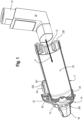
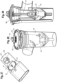
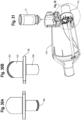
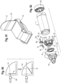
- a metered dose inhaler includes actuator boot 15, medicament canister 13 and adapter 802.
- the adapter 802 has an input end 804 shaped to receive a mouthpiece portion 806 of the boot, and an output end 808 shaped to be received in an opening of the input end of the valved holding chamber, for example as formed in the back piece 230.
- aerosolized medicament is discharged through the mouthpiece 806 and adapter 802 and into the valved holding chamber 2.
- the adapter 802 may include a housing 23 and a flow indicator 22.
- the adapter may be configured with an upstanding flange, or standard/upright 810, which extends radially beyond an outer circumferential surface of the holding chamber such that an electronic indicator 812, such as a light, disposed on the upright is visible to the user of the holding chamber. It should be understood that the adapter may be used without a holding chamber, with the output end 808 configured and serving as a mouthpiece that may be inserted into the mouth of a user.
- the flow indicator 22, circuitry and electronic indictor 812 function as described herein elsewhere.
- the back piece may be removed for cleaning, for example high temperature cleaning like dishwashing and/or autoclaving, which avoids the need to insulate the components from heat and/or water, e.g., water proofing. This in turn allows for the components to be manufactured with less expense.
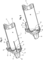
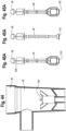
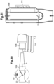
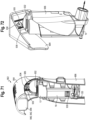
- the MDI applicator 902 may include a lever 904 and a housing 906.
- the constructions of various applicators are disclosed in U.S. Pub. No. 2014/0318534A1, filed March 14, 2014 , published October 30, 2014, and entitled "Metered Dose Inhaler Applicator".
- the components may be made of various material, including for example plastics used in the injection molding industry, for example polypropylene, ABS and acetal.
- the lever 904 which is moveably coupled to the housing 906, for example by way of a pivoting about a pivot axis/axle or hinge, assists the user, whether a patient or caregiver, in actuating a MDI.
- the housing is coupled to the MDI, for example with a stretchable seal 908.
- a flow indicator 22 is positioned in the housing 906, with an electronic indicator 220 disposed in the housing and visible to the user.
- the electronic circuitry is further disposed in the housing. Airflow may be entrained through various openings 911, 913 in the housing, for example in the top of the housing above the canister, or along the side of the housing as shown in FIG. 57 , causing the flow indicator 22 to move, with an associated signal being sent to the electronic indicator.
- the MDI boot 15 may be positioned into the applicator 902.
- the lever 904 is then rotated or pivoted relative to the housing about a pivot axis to an at-rest position, with a post 934 of the lever 904 positioned against an end of the canister 13 of the MDI.
- a force may be applied to the lever 904 of the MDI applicator 902, which lever 904 pivots about the pivot axis relative to the housing and MDI.
- the pivotal movement of the lever 904 and the post 934 transfers the force applied to the lever 904 to a downward force against the canister 13 of the MDI.
- the downward force against the canister 13 of the MDI causes a stem of the MDI to compress enough to open an internal valve of the MDI, medicine within the canister passes through the stem and out of a nozzle of the MDI in an aerosolized form for inhalation by a patient.
- the pivot axis is oriented substantially orthogonal to the mouthpiece, or an axis defined by the flow path exiting therefrom.
- the canister 13 of the MDI is forced into the actuator boot 15, which has a well receiving the valve stem. Once the canister has travelled far enough into the boot 15, the valve stem is depressed by the well until the valve is opened, thereby releasing the dose of aerosolized medicine.
- the MDI may be configured with a dose counter 930, for example a mechanical or electronic dose counter, which records the number of actuations of the canister.
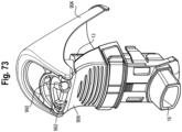
- the lever is pivotally coupled to the housing about an axis, which is oriented parallel to the flow path axis, or forms an acute angle relative thereto. This alternate lever position provides improved comfort to at least some users.
- a conductive portion e.g., strip 935
- a microcontroller 940 which may be housed in a case 942.
- the lever further includes a conductive portion, e.g., strip 936, that leads to a battery 944, which may also be housed in the case 942.
- a conductive portion, e.g., strip 932, is disposed on the housing 906, or alternatively on the canister or boot.
- the lever and housing may include other electrically conductive properties, or be integrally formed from a conductive material, isolated at attachment points by an insulator, or include various conductive portions, whether applied as a separate member or integrally formed.
- the case 942 may be disposed in and coupled to the lever 904. It should be understood that the strips 935, 936 and case 942, with battery 944 and controller 940, may be disposed on or coupled to the housing 906, boot 15 or canister 13, with strip 932 disposed on the lever.
- the strips 932, 935, 936 act as a (normally open) switch when the lever is a raised and/or at-rest position as shown in Figs. 71 and 72 .
- the strip 932 is brought into contact with and electrically connects strips 935, 936, with the strips 932, 935, 936 functioning as a closed switch.
- the completion of the circuit 936, 932, 935 signals the microcontroller to record an actuation of the MDI and acquire a time stamp associated with the actuation and store the data on the onboard memory, or communicate the data to a remote server or local computing device as further explained below.
- the switch is closed (or opened) when the lever has been displaced a predetermined minimum distance.
- the switch may alternatively be configured as a limit switch, wherein the switch is activated only when the lever has travelled a certain distance, or pivoted through a certain angle.
- the switch may be toggled by contacting the housing, MDI canister and/or actuator.
- the applicator may also be configured with an electronic indicator, such as an LED disposed on one of the lever or housing, which provides indicia that an actuation has occurred.
- the activation of the circuit by the closing of the switch may activate the electronic circuit utilizing low power circuitry enclosed within a portion of the lever or housing, for example the controller.
- the conductive properties may be specific to a small region of the lever and housing, e.g., a thin strip or other geometry, or the entire end of the housing may be conductive.
- the system uses capacitive sensing to determine when the lever has reached an actuation position. Feedback from the electronic indicator indicates that a sufficient actuation is achieved.
- the switch may be a normally closed switch, which activates the circuit when the switch is opened, for example when the lever is pivoted. Actuation may also be detected by a pressure sensor, a capacitive sensor, an inductive sensor, or other proximity sensor or switch. Upon reaching a predetermined second position, the electrically conductive properties of the lever and/or housing act as a switch, whether open or closed, to activate the electronic feedback utilizing low power circuitry enclosed with the housing 942, located on the lever, housing or MDI.
- the switch on the mating surface may be configured as two small conductive point contacts or conductive pads, emerging from an encapsulated, potted, conformal coated or sealed printed circuit board (PCB).
- the sensor within the encapsulation is a small pad and a ground pad matching the size of the PCB at a minimum to increase sensitivity of the sensor.
- the ground pad may be incorporated within the encapsulation or may be formed by a conductive path from the conductive region of the indicator along one of the applicator or MDI components. The human body may come in contact with the conductive path while holding the applicator and act as a ground.
- the electronic components may be integrated in the assembly of the device or embodied in a modular component or housing 942 that can be fit to any MDI or applicator. In either scenario, the electronic components are encapsulated, potted, conformal coated or sealed in the housing 942. It should be understood that in some examples the circuitry is not visible to the user or caregiver.
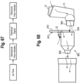
- the housing 906 is configured with an IR detector 962 and emitter 960. Then the canister is in the at-rest position, infrared radiation is emitted from the emitter 960 along a radiation path, reflected off of the canister 13 along a radiation path, and detected by the detector 62.
- the canister moves downwardly in response to the force from the lever 904 until the canister is no longer in the radiation path. In other words, in the actuated position, the canister 13 is no longer in a position to reflect the infrared radiation path, and the change of signal from the detector 962 is used to infer actuation.
- the emitter 960 and detector 962 may be positioned 180 degrees apart from one another, with the canister 13 breaking the radiation beam there between.
- the canister moves out the path, such that the detector 962 detects the radiation beam from the emitter 960, and thereby senses and sends a signal associated with an actuation of the MDI.
- Light curtain and reflection/proximity sensing embodiments and configurations may also be suitable.
- a force sensor is provided on the lever.
- the force sensor may serve the function of the post 934, or be incorporated into the post. Actuation of the MDI occurs at a fairly consistent force. Accordingly, the force sensor may be correlated with the actuation force, and send a signal when the lever is pivoted to apply such a force. For example, once a certain threshold value is recorded or detected by the sensor, an actuation is recorded/registered.
- the microcontroller, battery and case may be incorporated into the lever as disclosed above.
- the force sensor may be applied to the housing 906 or MDI, and electronically communicate with the electronic components associated therewith.
- the different modules and embodiments may record and register actuations, individually and cumulatively, including the time and date of the actuation, and/or the location when the device is configured and/or associated with a GPS module, which may be embedded in, or housed with, the microcontroller.
- the accumulated data may be analyzed to provide feedback on when and how the device is used, and/or compliance with particular delivery protocols prescribed by the caregiver.
- data may be wirelessly communicated to a smart phone, local computing device and/or remote computing device to interpret and act on the raw sensor data.
- the MDI applicator 902 may be used with a holding chamber (e.g., FIGS. 1-5 ), which is configured with a flow indicator.
- the MDI applicator 902 may be configured with a module as disclosed above that records and registers actuations, individually and cumulatively, including the time and date of the actuation, and/or the location when the device is configured and/or associated with a GPS module, which may be embedded in, or housed with, a microcontroller disposed on or in the housing.
- the accumulated data may be analyzed to provide feedback on when and how the device is used, and/or compliance with particular delivery protocols prescribed by the caregiver.
- data may be wirelessly communicated to a smart phone, local computing device and/or remote computing device to interpret and act on the raw sensor data.
- the MDI applicator 902 includes circuitry for transmitting raw sensor data in real time to a local device, such as a smart phone.
- the smart phone may display graphics or instructions to the user and implement processing software to interpret and act on the raw data.
- the smart phone may include software that filters and processes the raw sensor data and outputs the relevant status information contained in the raw sensor data to a display on the smart phone.
- the smart phone or other local computing device may alternatively use its local resources to contact a remote database or server to retrieve processing instructions or to forward the raw sensor data for remote processing and interpretation, and to receive the processed and interpreted sensor data back from the remote server for display to the user or a caregiver that is with the user of the smart MDI applicator.
- proactive operations relating to the MDI applicator may be actively managed and controlled. For example, if the smart phone or other local computer in proximity to the MDI applicator, or other device (e.g., holding chamber, peak flow meters, dry powder inhalers, nebulizers, etc.), determines that the sensor data indicates that a dose has been administered, the smart phone or other local computing device may communicate that information to the user or caregiver.
- the smart phone or other local computing device may communicate that information to the user or caregiver.
- real-time data gathered in the smart MDI applicator or other device may trigger the remote server to track down and notify a physician or supervising caregiver regarding a problem with the particular session or a pattern that has developed over time based on past sessions for the particular user.
- the remote server may generate alerts to send via text, email or other electronic communication medium to the user's physician or other caregiver.
- the data may be uploaded to a mobile application via wireless communications (e.g., Bluetooth) whenever the mobile device (e.g., phone, tablet, laptop, etc.) is in range for synchronizing the data.
- the data my then be analyzed on the application and presented to the user in a manner that is beneficial for the user/patient's engagement and adherence/compliance.
- the data may also be forwarded to a cloud service via WiFi or mobile network so that the data may be reviewed by other caregivers, healthcare providers and/or payers (e.g., insurance companies).
- the applicator 902 By combining the applicator 902 and valved holding chamber configured with an electronic indicator 220, a more accurate calculation of the end of treatment may be provided to the user or care giver.
- the applicator 902, or microcontroller 940 registers an actuation of the MDI and communicates that information, or sends a signal, to a processor, for example by wireless communication.
- the applicator and valved holding chamber may communicate by direct communication links, for example hard wiring when the applicator is inserted into the valved holding chamber.
- the mechanical flow indicator 22 provides input, or sends a signal, that inhalation has commenced by closing a switch, or actuating another sensor, as disclosed above.
- That information is communicated to a microcontroller (MCU) or microprocessor.
- An internal clock records the time, while the processor identifies whether the MDI actuation has taken place by way of communication of the signal from the applicator 902. If the actuation has not transpired, the internal clock loops, and/or computes the time from actuation, such that data is gathered as to the length of the inhalation through the valved holding chamber, which causes the flow indicator associated therewith to move or deform and send a signal, as well as the length of the inhalation after the MDI is actuated.
- a volume calculation is performed, using the data as to the inhalation flow before and after actuation, with electronic feedback provided. In this way, feedback is provided that treatment is finished, or that sufficient volume has been inhaled subsequent to the actuation of the MDI.
- the data may also be collected and communicated as noted to the healthcare provider.
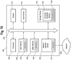
- the electronic circuitry in the MDI applicator or other device may include some or all of the capabilities of a computer 500 in communication with a network 526 and/or directly with other computers.
- the computer 500 may include a processor 502, a storage device 516, a display or other output device 510, an input device 512, and a network interface device 520, all connected via a bus 508.
- the computer may communicate with the network.
- the processor 502 represents a central processing unit of any type of architecture, such as a CISC (Complex Instruction Set Computing), RISC (Reduced Instruction Set Computing), VLIW (Very Long Instruction Word), or a hybrid architecture, although any appropriate processor may be used.
- the processor 502 executes instructions and includes that portion of the computer 500 that controls the operation of the entire computer.
- the processor 502 typically includes a control unit that organizes data and program storage in memory and transfers data and other information between the various parts of the computer 500.
- the processor 502 receives input data from the input device 512 and the network 526 reads and stores instructions (for example processor executable code) 524 and data in the main memory 504, such as random access memory (RAM), static memory 506, such as read only memory (ROM), and the storage device 516.
- the processor 502 may present data to a user via the output device 510.
- the computer 500 is shown to contain only a single processor 502 and a single bus 508, the disclosed embodiment applies equally to computers that may have multiple processors and to computers that may have multiple busses with some or all performing different functions in different ways.
- the storage device 516 represents one or more mechanisms for storing data.
- the storage device 516 may include a computer readable medium 522 such as read-only memory (ROM), RAM, non-volatile storage media, optical storage media, flash memory devices, and/or other machine-readable media.
- ROM read-only memory
- RAM random access memory
- the storage device 516 may include a controller (not shown) and a computer readable medium 522 having instructions 524 capable of being executed on the processor 502 to carry out the functions described above with reference to processing sensor data, displaying the sensor data or instructions based on the sensor data, controlling aspects of the smart MDI applicator or other device (e.g., holding chamber, peak flow meters, dry powder inhalers, nebulizers, etc.) to alter its operation, or contacting third parties or other remotely located resources to provide update information to, or retrieve data from those remotely located resources.
- some or all of the functions are carried out via hardware in lieu of a processor-based system.
- the controller is a web browser, but in other embodiments the controller may be a database system, a file system, an electronic mail system, a media manager, an image manager, or may include any other functions capable of accessing data items.
- the storage device 516 may also contain additional software and data (not shown), which is not necessary to understand the invention.
- the output device 510 is that part of the computer 500 that displays output to the user.
- the output device 510 may be a liquid crystal display (LCD) well-known in the art of computer hardware.
- the output device 510 may be replaced with a gas or plasma-based flat-panel display or a traditional cathode-ray tube (CRT) display.
- CTR cathode-ray tube
- any appropriate display device may be used.
- only one output device 510 is shown, in other embodiments any number of output devices of different types, or of the same type, may be present.
- the output device 510 displays a user interface.
- the input device 512 may be a keyboard, mouse or other pointing device, trackball, touchpad, touch screen, keypad, microphone, voice recognition device, or any other appropriate mechanism for the user to input data to the computer 500 and manipulate the user interface previously discussed. Although only one input device 512 is shown, in another embodiment any number and type of input devices may be present.
- the network interface device 520 provides connectivity from the computer 500 to the network 526 through any suitable communications protocol.
- the network interface device 520 sends and receives data items from the network 526 via a wireless or wired transceiver 514.
- the transceiver 514 may be a cellular frequency, radio frequency (RF), infrared (IR) or any of a number of known wireless or wired transmission systems capable of communicating with a network 526 or other smart devices 102 having some or all of the features of the example computer of FIG. 2 .
- the bus 508 may represent one or more busses, e.g., USB, PCI, ISA (Industry Standard Architecture), X-Bus, EISA (Extended Industry Standard Architecture), or any other appropriate bus and/or bridge (also called a bus controller).
- the computer 500 may be implemented using any suitable hardware and/or software, such as a personal computer or other electronic computing device.
- the computer 500 may be a portable computer, laptop, tablet or notebook computers, smart phones, PDAs, pocket computers, appliances, telephones, and mainframe computers are examples of other possible configurations of the computer 500.
- the network 526 may be any suitable network and may support any appropriate protocol suitable for communication to the computer 500.
- the network 526 may support wireless communications.
- the network 526 may support hard-wired communications, such as a telephone line or cable.
- the network 526 may support the Ethernet IEEE (Institute of Electrical and Electronics Engineers) 802.3x specification.
- the network 526 may be the Internet and may support IP (Internet Protocol).
- the network 526 may be a LAN or a WAN. In another embodiment, the network 526 may be a hotspot service provider network. In another embodiment, the network 526 may be an intranet. In another embodiment, the network 526 may be a GPRS (General Packet Radio Service) network. In another embodiment, the network 526 may be any appropriate cellular data network or cellbased radio network technology. In another embodiment, the network 526 may be an IEEE 802.11 wireless network. In still another embodiment, the network 526 may be any suitable network or combination of networks. Although one network 526 is shown, in other embodiments any number of networks (of the same or different types) may be present.
- GPRS General Packet Radio Service
- the computing device In the case of program code execution on programmable computers, the computing device generally includes a processor, a storage medium readable by the processor (including volatile and non-volatile memory and/or storage elements), at least one input device, and at least one output device.
- One or more programs may implement or use the processes described in connection with the presently disclosed subject matter, e.g., through the use of an API, reusable controls, or the like. Such programs may be implemented in a high level procedural or object-oriented programming language to communicate with a computer system. However, the program(s) can be implemented in assembly or machine language, if desired. In any case, the language may be a compiled or interpreted language and it may be combined with hardware implementations.
- exemplary embodiments may refer to using aspects of the presently disclosed subject matter in the context of one or more standalone computer systems, the subject matter is not so limited, but rather may be implemented in connection with any computing environment, such as a network or distributed computing environment. Still further, aspects of the presently disclosed subject matter may be implemented in or across a plurality of processing chips or devices, and storage may similarly be spread across a plurality of devices. Such devices might include personal computers, network servers, and handheld devices, for example.
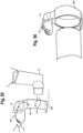
- adapters 1000, 1002 for use in a ventilator circuit are shown, with the adapters inserted into a flow path between the ventilator and a user interface.
- the construction of the adapters is disclosed in U.S. Pub. No. 2014/0360498, filed March 14, 2014 , published December 11, 2014, and entitled "Ventilator Circuit, Adapter for Use in Ventilator Circuit and Methods for The Use Thereof".
- the adapters 1000, 1002 include medication delivery ports 1004, 1006, which are suited and configured to receive medicament delivery devices, including for example and without limitation inhalers 1008 and nebulizers 1010.
- the adapters 1000, 1002 are configured with a mechanical flow indicator 22 disposed in the flow path.
- the adapter may be configured with an electronic indicator 220, such as a light, disposed on an exterior surface of the adapter such that the indicator is visible to the user or care giver.
- the flow indicator 22, circuitry and electronic indictor 220 function as described herein with respect to other embodiments.
- drug delivery is preferably performed at the onset of an inhalation cycle, which may be difficult for a care giver to ascertain by just listening to the ventilator machine.
- the indicator 220 provides more certainty, and helps prevent drug delivery from being performed during exhalation.
- the drug delivery devices 1008, 1010 are actuated when the mechanical indicator 22, which may be visible to the user, moves and/or when the electronic indicator 220 provides indicia, e.g., by illuminating.
- the indicator 22 may be made of silicone, and may operate as a switch (normally open or closed), or be configured with a flexible resistor in a circuit, as described herein elsewhere. As shown, the indicators 22 are positioned on the upper side of the adapter, or extend downwardly therefrom, when such adapters are in their normal use positions to prevent drug pooling or accumulation against the indicator 22.
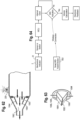
- a compressor 1020 may be configured with a mechanical flow indicator, which moves or is deformed in response to a fluid flow (P), whether gas or liquid.
- the flow indicator 22 is coupled to a circuit, which provides a signal to an electronic indicator 220 when actuated.
- the electronic indicator provides indicia to the user that flow is occurring.
- the flow indicator 22 is embedded in a flow path in the compressor 1020, while an electronic indicator 220 is provided on or in the compressor, and is visible to the user if embodied as a visual indicator.
- the flow indicator may be positioned in a connector, or adapter, having an insert portion received in an end portion 1026 of the tubing 1022 and a receiving end connector portion 1028, which is shaped and configured to connect to the same devices as the end portion 1026 of the tubing.
- the flow indicator may alternatively be directly positioned in the tubing 1022 and operably connected to an electronic indicator, whether by direct circuitry or wirelessly.
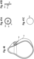
- a peak flow meter 1050 is configured with a mechanical flow indicator 22, for example a flow indicator configured with a flexible resistor.
- the amount of flow deflects the indicator and deforms or bends the resistor varying amounts.
- the amount of deflection or deformation may be correlated with a varying display by an electronic indicator, for example an array of LED's 1040, with a greater number of LED's being illuminated as the flow increases.
- the indicator 1040 may also be configured with different color lights providing indicia about different flow levels.
- Usage data may also be collected and tracked, and connected to a computer or smartphone app, as described above with respect to the MDI applicator, such that the data may be shared with the patient, care giver or other healthcare providers.
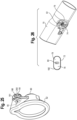
- the patient interface includes a mask 52 secured to an adapter 62, which in turn may be secured to the end of the valved holding chamber or the baffle section.
- the mask includes an exhalation valve 54, which functions as a flow indicator.
- Other patient interfaces may include for example and without limitation, various mouthpieces, masks, endotracheal tubes, etc.
- the valve may have a central post 56, which engages an opening on the mask and secures the valve to the mask.
- a protective dome or shroud 58 may be disposed around the valve.
- the exhalation valve 54 is inserted into an exit port formed in a nasal reception area of a mask and is attached thereto.
- a cylindrical input port 60 of the mask is placed over the exit port of the adapter and attached thereto by a friction fit, or by way of an interface of a rib 64 formed on the input port engaging a channel or corresponding rib on the mask 52.
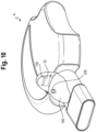
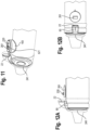
- a mouthpiece 70 incorporated for example into a dry powder inhaler ( FIG. 10 ), a nebulizer ( FIG. 8 ), or a oscillating positive expiratory pressure device ( FIG. 9 ), includes an exhalation valve 72 secured over an opening 74 in the mouthpiece, which defines a valve seat 76.
- the valve is configured with two flaps 78, such as a butterfly valve in one embodiment, with a central post or protuberance 82 extending through an opening 80 in the valve and securing it to the exterior of the mouthpiece.
- a shield (not shown) may be disposed over the valve to protect it from tampering.
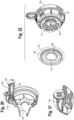
- a nebulizer 90 includes a chamber 92, a diaphragm 96 and a dial 98 disposed on top of an actuator 94.
- the actuator 94 and dial 98 move axially along axis 107 during inhalation.
- a bottom 104 of the dial 98 engages an inner periphery of the diaphragm 96, and a bottom 102 of the actuator has a surface that engages a nozzle cover 100, as the actuator is moved axially downwardly during inhalation.
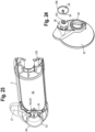
- valved holding chamber 110 which may be used for example and without limitation in a ventilator circuit
- the valved holding chamber has a connector component 112, which defines a ventilator port.
- the connector has first and second passageways 114, 116 separated by a wall 118.
- An integrally formed inhalation/exhalation valve 120 has a pair of flaps 122, 124 extending from opposite directions from a base portion 126.
- the connector has a valve seat 128 for the inhalation valve 122, while the chamber has a valve seat 130 for the exhalation valve 124.
- Various aspects of the valved holding chamber and connector are disclosed in U.S. Patent No. 8,875,706 , the entire disclosure of which is hereby incorporated herein by reference.
- various components of the above-described medicament delivery devices are flow indicators, and in particular mechanical flow indicators, which move dynamically in response to a flow.
- the various components regardless of whether they are visible, provide indicia of a flow, whether inhalation or exhalation.
- the various components may or may not be visible to the user and/or caregiver.
- the movement of the flow indicators provides input to an electronic flow indicator that sufficient inhalation has occurred. For example, the number of movements of the flow indicator 22, whether upon inhalation or exhalation (or both), during a breathing cycle (defined as the number of breaths (N) taken while the medicament is being administered), or the cumulative duration (T) of the change of position of the flow indicator during the breathing cycle, provides input to the circuitry that is correlated with sufficient inhalation.
- a predetermined number or duration (whether singular or cumulative) of contacts, or sufficient proximity to contact, between the flow indicator 22 and a seat, or contact point provides input to and actuates the electronic indicator, for example by displaying a green light or other indicia. If the number of movements of the flow indicator, or the duration (singular or cumulative) thereof, is not achieved, or if sufficient contact(s) or proximity of contact(s) is not achieved, then the electronic circuit will not activate the electronic indicator, or alternatively, the electronic indicator may be activated to show inadequate medicament administration, for example by displaying a yellow or red light, an auditory signal, vibration (e.g., tactile) or other indicia.
- the visual flow indicator 22 defines a mechanical flow indicator having a conductive strip 130, or including other electrically conductive properties, which act as a (normally open) switch closing a circuit when it seals against a seat 132.
- the activation of the circuit by the closing of the switch thereby activates the electronic feedback utilizing low power circuitry enclosed within a portion of the user interface, such as a mouthpiece or mask adapter.
- the conductive properties may be specific to a small region of the flow indicator, e.g., a thin strip or other geometry, or the entire face of the flow indicator may be conductive.
- the system uses capacitive sensing to determine when the flow indicator has reached a second position corresponding to a predetermined flow.
- Feedback from the electronic indicator 220 indicates that a sufficient inhalation flow rate is achieved and/or that proper treatment has been completed based on a number of breaths and/or the volume calculated based on the minimum flow required to seal the mechanical flow indicator and/or the length to time in which the seal (switch) is maintained.
- the minimum flow required to seal the mechanical flow indicator may be between 3-5L/min.
- the switch may be a normally closed switch, which activates the circuit when the switch is opened, for example when an inhalation or exhalation valve (flow indicator) is operated.
- the number of movements of the flow indicator e.g., inhalation or exhalation valve or actuator
- duration of the opening of the switch may provide input to the circuit ( FIG. 54 ) that sufficient medication delivery has been achieved, with the circuit then activating the electronic indicator.
- the mechanical flow indicator is defined by the inhalation valve 241, 122, 1060 which may function as the input or switch for the electronic feedback.
- the inhalation valve may be configured with a region 150, 152 or material having conductive properties, for example around the inner or outer periphery 33 of the annular valve, or along a free end 154 of the inhalation flap 122, that mate with a mating surface, e.g., valve seat 42, 128, forming a part of an electronic circuit, for example in the baffle, also having a conductive material or region.
- a mating surface e.g., valve seat 42, 128, forming a part of an electronic circuit, for example in the baffle, also having a conductive material or region.
- movement detection may be performed by a pressure sensor, a capacitive sensor, an inductive sensor, or other proximity sensor or switch.
- the electrically conductive properties of the indicator act as a switch, whether open or closed, to activate the electronic feedback utilizing low power circuitry enclosed with a housing 160, located on the chamber housing, mouthpiece, mask adapter or other component.
- the switch on the sealing surface 42, 128 where the flow indicator mates upon its second position may be configured as two small conductive point contacts or conductive pads, emerging from an encapsulated, potted, conformal coated or sealed printed circuit board (PCB) or microcontroller 261.
- PCB printed circuit board
- the sensor within the encapsulation is a small pad with a sensing area no larger than 25 mm 2 and a ground pad matching the size of the PCB at a minimum to increase sensitivity of the sensor.
- the ground pad may be incorporated within the encapsulation or may be formed by a conductive path from the conductive region of the indicator along the body of the chamber. The human body may come in contact with the conductive path while holding the chamber and act as a ground.
- the mechanical flow indicator is configured as a duckbill valve 1060, which has a pair of flaps 1064 that open to form a central opening 1062 in response to a flow through the valve.
- the valve provides one-way flow control.
- the valve flaps 1064 may have conductive strips 1066 that are in contact with the valve is in a normally closed position, such that an opening of the valve cause the circuit to identify a flow and send a signal to an electronic indicator 220 and/or record an opening in a database.
- the valve flaps 1064 may alternatively be provided with a flexible resistor 1068, which deflects with the valve flaps, in a circuit that signals the electronic indicator 220 to provide indicia that flow has occurred, for example by illuminating.
- the sensor may alternatively be configured as a capacitive sensor.
- the electronic components in the various embodiments may be integrated in the assembly of the device, or embodied in a modular component or housing 160 that can be fit to any valved holding chamber (or other respiratory device).
- the electronic components are encapsulated, potted, conformal coated or sealed in an area preferably between 25x25x5mm (LxWxH) and 45x45x20mm (LxWxH).
- LxWxH 25x25x5mm
- LxWxH 45x45x20mm
- the electronic indicator and flow indicator may be incorporated into a removable patient interface, e.g., mask, mouthpiece, adapter, etc., that may be used by the same patient / user with more than one respiratory care system.
- the circuitry is not visible to the user or caregiver.
- the mechanical flow indicator include the exhalation valve 54, 72, 124 on the mask, mouthpiece or connector, which act as the switch (normally open or closed) described above.
- the valve or other moving member
- the valve has conductive properties in a region 180 (outer periphery of valve 54), 182 (periphery of valve 72), 184 (free edge of flap 124) in contact with a sealing surface 181, 76, whether in a normally open or closed configuration, also having a conductive material or region. While contact is maintained, the switch is on or off (dependent on what feedback is desired) and the switch changes state when flow is enabled to overcome the valve (or other moving member).
- a proximity sensor or switch may be incorporated into a chamber that accepts an MDI canister to provide indication that the canister is sufficiently inserted in the device.
- an optic sensor 190 may be provided to signal 192 when the flow indicator 22 has moved to a second position, with sensor 190 providing input to the circuit.
- either of the multipurpose inhalation/exhalation valves 122, 124 on the chamber may be configured with a conductive material or region 152, 184 that closes a switch during inhalation and/or exhalation.
- the chamber may be utilized in combination with mechanical ventilation, a manual resuscitation bag or a standard aerosol resuscitation mask.
- the bottom 104 of the dial and an inner periphery 106 of the diaphragm on a nebulizer may be configured with a conductive material or region, which complete a switch when coming into contact, for example during inhalation as the actuator moves axially downwardly.
- a bottom surface of the actuator has a conductive material or region that comes into contact with a conductive material or region on the muzzle cover 100 as the actuator moves axially, thereby closing or opening a switch as described above.
- a piston 200 on a manometer may be configured with a magnetic or conductive material or region, with a variable output relative to pressure provides an input to an electronic indicator.
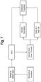
- the various steps performed by the system are shown in the block/flow diagram of FIG. 7 .
- the sensor or switch input which may also be related to a mechanical feedback, relays information to a microcontroller unit 261.
- the microcontroller 261 also shown in FIGS. 3 , 12A and B , 13 20 and 22 , controls the electronic feedback output, and transmits a signal to the electronic indicator (e.g., LED) 220, and may provide output as disclosed herein.
- a light pipe may diffuse the light from the LED.
- a battery 521 provides power to the circuit.
- the entirety of the system may be washed by the user without special attention to the electronics, which may also be configured to withstand the heat of a dishwasher. Alternatively, the electronics may be removed prior to washing or exposure to heat.
- the battery chemistry is a lithium coin cell, specifically poly-carbon monofluoride lithium that is specifically designed to operate at temperatures up to 125C, has an annual deterioration rate as low as 0.5% and has a relatively flat discharge voltage curve. Incorporating sufficient thermal insulation properties in the encapsulation material may allow for the entirety of the device to withstand autoclaving processes.
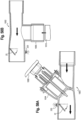
- linear induction may be utilized to generate power for the circuit and thereby eliminate the need for a battery.
- the linear electrical generator is composed of one or more neodymium magnet(s) 210 that move reciprocally back and forth along a longitudinal axis 51 (or parallel thereto) or direction within a center space defined by a copper coil 212 wrapped around the axis 51 when a chamber 602 is shaken. This shaking motion is necessary prior to actuating an MDI 13, 15 and does not imply an additional step in the drug delivery process. The shaking induces a current in the coil 212, which is stored in a supercapacitor 214 to power the circuitry connected to an electronic indicator 220.
- an internal timer on the device When taking the device out of the package the first time, an internal timer on the device will activate. For example, a light sensor (or other sensor) will activate an internal clock to begin tracking elapsed time. Alternatively, the timer may be activated upon the first use.
- the device will function as described herein for the duration of a predetermined recommended life of the device as determined by the timer, at which point the electronic indicator will either stop functioning or produce a warning signal different from the previously seen signal that indicates prior inhalation and/or treatment completion.
- This warning signal e.g., red LED
- the mechanical flow indicator will continue to function after the expiration of the predetermined recommended life, e.g., 1 year, so as to not diminish the safe use of the device.
- the user interface including for example the mouthpiece or mask adapter, holding chamber and retainer may be made of transparent anti-static material (ABS).
- a backpiece 230 which interfaces with a MDI 13, 15, may be made of an ultra-soft thermoplastic elastomer.
- the inhalation valve may be made of silicone.
- the mechanical flow indicator may be made of silicone with magnetic or conductive properties, including a conductive region made of a conductive silicone, metal foil or a conductive coating/ink.
- the conductive materials may be silver oxide, carbon black, aluminum, or other known conductive materials.
- the electronics, such as the microcontroller 261, may be potted conformal coated, sealed, or encapsulated in silicone, epoxy, urethane, hot melt or other materials resistant to high temperatures.
- the electronic indicator 220 is a visual indicator (e.g., LED or LCD display), which provides the electronic feedback.
- Other electronic indicators may be used, for example an audible signal or feedback, such as a buzzer, a sequence of LED's or other visual cues showing a percentage of treatment completion (e.g., LED bar graph), a segmented numerical display of the treatment percentage completed, an LED or OLED screen showing the progress or numerical representation of the flow or volume remaining, or possible connection to and communication with a smart phone application via bluetooth low energy (BLE) to show data from inhalation or to incorporate flow data into a game.
- BLE bluetooth low energy
- a medicament will fill the chamber, for example when an inhalation valve is closed.
- the mechanical flow indicator whether separately configured or defined by the inhalation valve, or actuator, is in a neutral position since no inhalation is taking place. Accordingly, the electronic indicator, e.g. LED, is off as no feedback is being provided.
- the inhalation valve will open, creating a negative pressure and causing the mechanical flow indicator to move forward from a first position to a second position until the flow indicator creates a seal with a seat at a predetermined, sufficient inhalation flow.
- a circuit is closed and the electronic feedback is activated, for example by an LED, which provides feedback to indicate proper inhalation.
- an LED which provides feedback to indicate proper inhalation.
- a green LED will provide positive feedback.
- the LED will stay illuminated while the seal is maintained, and turns off when the seal is broken, e.g., at the end of inhalation or upon improper inhalation.
- the circuit and electronic indicator may also be configured to be activated when a predetermined number of movements of the flow indicator, or a cumulative duration of such movements, has been achieved.
- the LED may illuminate and stay on for an extended period of time when treatment is complete to relay that the user has completed a successful treatment, for example requiring multiple breathing cycles.
- the LED At the end of predetermined life for the chamber or other components (e.g., 1 year), as tracked for example by the internal timer or clock, the LED will be deactivated, or the LED will provide a warning signal (e.g., turn red), indicating that the device should be replaced.
- a warning signal e.g., turn red
Landscapes
- Health & Medical Sciences (AREA)
- Engineering & Computer Science (AREA)
- Life Sciences & Earth Sciences (AREA)
- General Health & Medical Sciences (AREA)
- Veterinary Medicine (AREA)
- Hematology (AREA)
- Biomedical Technology (AREA)
- Animal Behavior & Ethology (AREA)
- Anesthesiology (AREA)
- Public Health (AREA)
- Heart & Thoracic Surgery (AREA)
- Pulmonology (AREA)
- Bioinformatics & Cheminformatics (AREA)
- Emergency Medicine (AREA)
- Biophysics (AREA)
- Measurement Of The Respiration, Hearing Ability, Form, And Blood Characteristics Of Living Organisms (AREA)
- Infusion, Injection, And Reservoir Apparatuses (AREA)
Applications Claiming Priority (5)
| Application Number | Priority Date | Filing Date | Title |
|---|---|---|---|
| US201662312830P | 2016-03-24 | 2016-03-24 | |
| US201662337626P | 2016-05-17 | 2016-05-17 | |
| US201762465479P | 2017-03-01 | 2017-03-01 | |
| PCT/IB2017/051695 WO2017163211A1 (en) | 2016-03-24 | 2017-03-23 | Respiratory care system with electronic indicator |
| EP17769554.1A EP3432955B1 (en) | 2016-03-24 | 2017-03-23 | Respiratory care system with electronic indicator |
Related Parent Applications (1)
| Application Number | Title | Priority Date | Filing Date |
|---|---|---|---|
| EP17769554.1A Division EP3432955B1 (en) | 2016-03-24 | 2017-03-23 | Respiratory care system with electronic indicator |
Publications (3)
| Publication Number | Publication Date |
|---|---|
| EP3831432A1 EP3831432A1 (en) | 2021-06-09 |
| EP3831432C0 EP3831432C0 (en) | 2023-06-07 |
| EP3831432B1 true EP3831432B1 (en) | 2023-06-07 |
Family
ID=59901171
Family Applications (2)
| Application Number | Title | Priority Date | Filing Date |
|---|---|---|---|
| EP21153010.0A Active EP3831432B1 (en) | 2016-03-24 | 2017-03-23 | Respiratory care system with electronic indicator |
| EP17769554.1A Active EP3432955B1 (en) | 2016-03-24 | 2017-03-23 | Respiratory care system with electronic indicator |
Family Applications After (1)
| Application Number | Title | Priority Date | Filing Date |
|---|---|---|---|
| EP17769554.1A Active EP3432955B1 (en) | 2016-03-24 | 2017-03-23 | Respiratory care system with electronic indicator |
Country Status (8)
| Country | Link |
|---|---|
| US (2) | US10894142B2 (enExample) |
| EP (2) | EP3831432B1 (enExample) |
| JP (2) | JP7155010B2 (enExample) |
| CN (2) | CN109152891B (enExample) |
| CA (1) | CA3019203A1 (enExample) |
| ES (1) | ES2956026T3 (enExample) |
| MX (3) | MX390900B (enExample) |
| WO (1) | WO2017163211A1 (enExample) |
Families Citing this family (21)
| Publication number | Priority date | Publication date | Assignee | Title |
|---|---|---|---|---|
| WO2017016316A1 (zh) * | 2015-07-28 | 2017-02-02 | 纳智源科技(唐山)有限责任公司 | 电子烟气动传感器、气流处理装置及电子烟 |
| US10894142B2 (en) * | 2016-03-24 | 2021-01-19 | Trudell Medical International | Respiratory care system with electronic indicator |
| WO2017199215A1 (en) | 2016-05-19 | 2017-11-23 | Trudell Medical International | Smart valved holding chamber |
| EP3481476B1 (en) | 2016-07-08 | 2021-09-08 | Trudell Medical International | Smart oscillating positive expiratory pressure device |
| JP7093353B2 (ja) | 2016-12-09 | 2022-06-29 | トゥルーデル メディカル インターナショナル | スマートネブライザ |
| US20190059811A1 (en) * | 2017-08-27 | 2019-02-28 | Charles Dashiell | Combination peak flow meter, inhaler, and nebulizer |
| EP3485930B1 (en) | 2017-11-20 | 2021-04-14 | Presspart Gmbh & Co. Kg | Inhalation system |
| CA3086890A1 (en) * | 2018-01-04 | 2019-07-11 | Trudell Medical International | Smart oscillating positive expiratory pressure device |
| US10388412B1 (en) * | 2018-03-29 | 2019-08-20 | Reciprocal Labs Corporation | Decreased latency wireless communication for use with medicament devices |
| US11590299B1 (en) * | 2018-05-13 | 2023-02-28 | Keith Good | Methods and systems for metered dose inhalation monitoring and communication |
| US11395890B2 (en) | 2018-06-04 | 2022-07-26 | Trudell Medical International | Smart valved holding chamber |
| WO2019236662A1 (en) | 2018-06-05 | 2019-12-12 | Teleflex Medical Incorporated | Valved spacer for inhalation device |
| EP3682923B1 (en) * | 2019-01-15 | 2021-12-15 | Air Liquide Medical Systems S.R.L. | Medication inhaler for aerosol pulmonary delivery with visual feedback system |
| AU2020338979B2 (en) * | 2019-08-27 | 2025-09-25 | Trudell Medical International Inc. | Smart oscillating positive expiratory pressure device |
| US11911558B2 (en) * | 2019-09-03 | 2024-02-27 | Trudell Medical International | Medical device with energy harvesting system |
| EP3815601A1 (en) * | 2019-11-01 | 2021-05-05 | Koninklijke Philips N.V. | Evaluating skin |
| US20210319886A1 (en) * | 2020-04-10 | 2021-10-14 | GE Precision Healthcare LLC | Systems and methods for determining and visualizing medical device resource availability |
| US20210322597A1 (en) * | 2020-04-17 | 2021-10-21 | Energy Focus, Inc. | Uv disinfection system |
| GB202010540D0 (en) * | 2020-07-09 | 2020-08-26 | Smiths Medical International Ltd | Respiratory therapy device |
| EP4282452B1 (en) * | 2022-05-24 | 2024-04-10 | Galemed Corporation | Nebulizer with detecting structure |
| AU2024258536A1 (en) * | 2023-04-21 | 2025-10-30 | Trudell Medical International Inc. | Valved holding chamber with flow indicator |
Family Cites Families (256)
| Publication number | Priority date | Publication date | Assignee | Title |
|---|---|---|---|---|
| US3624568A (en) * | 1970-10-26 | 1971-11-30 | Bell Telephone Labor Inc | Magnetically actuated switching devices |
| DE2138623A1 (de) * | 1971-08-02 | 1973-02-15 | Kugelfischer G Schaefer & Co | Kraftstoffzufuhrregeleinrichtung |
| GB1479283A (en) * | 1973-07-23 | 1977-07-13 | Bespak Industries Ltd | Inhaler for powdered medicament |
| US4206644A (en) * | 1977-09-29 | 1980-06-10 | National Research Development Corporation | Respiration sensors |
| US4481514A (en) * | 1982-03-09 | 1984-11-06 | Beukers Laboratories, Inc. | Microprocessor based radiosonde |
| DE3227805A1 (de) * | 1982-07-24 | 1984-01-26 | Robert Bosch Gmbh, 7000 Stuttgart | Elektrisches potentiometer |
| US4662564A (en) * | 1984-05-15 | 1987-05-05 | Diesel Kiki Co., Ltd. | Fuel injection nozzle with timing sensor |
| US4984158A (en) * | 1988-10-14 | 1991-01-08 | Hillsman Dean | Metered dose inhaler biofeedback training and evaluation system |
| US5012804A (en) * | 1989-03-06 | 1991-05-07 | Trudell Medical | Medication inhaler with adult mask |
| US5012803A (en) * | 1989-03-06 | 1991-05-07 | Trudell Medical | Modular medication inhaler |
| SE466684B (sv) | 1989-03-07 | 1992-03-23 | Draco Ab | Anordning vid en inhalator samt foerfarande foer att med anordningen registrera medicinering med inhalator |
| ES2087911T3 (es) * | 1989-04-28 | 1996-08-01 | Riker Laboratories Inc | Dispositivo de inhalacion de polvo seco. |
| US5042467A (en) * | 1990-03-28 | 1991-08-27 | Trudell Medical | Medication inhaler with fitting having a sonic signalling device |
| GB9023282D0 (en) * | 1990-10-25 | 1990-12-05 | Riker Laboratories Inc | Inhalation device |
| US5431154A (en) | 1991-11-29 | 1995-07-11 | Seigel; David | Incentive metered dose inhaler |
| US5363842A (en) * | 1991-12-20 | 1994-11-15 | Circadian, Inc. | Intelligent inhaler providing feedback to both patient and medical professional |
| US5284133A (en) | 1992-07-23 | 1994-02-08 | Armstrong Pharmaceuticals, Inc. | Inhalation device with a dose-timer, an actuator mechanism, and patient compliance monitoring means |
| US5333106A (en) | 1992-10-09 | 1994-07-26 | Circadian, Inc. | Apparatus and visual display method for training in the power use of aerosol pharmaceutical inhalers |
| NZ250105A (en) | 1992-11-09 | 1996-07-26 | Monaghan Canadian Ltd | Inhalator mask; one-way valve opens upon exhalation |
| US5819726A (en) | 1993-01-29 | 1998-10-13 | Aradigm Corporation | Method for the delivery of aerosolized drugs to the lung for the treatment of respiratory disease |
| WO1995007723A1 (en) | 1993-09-16 | 1995-03-23 | Medtrac Technologies Inc. | Inhaler having an attachable dosing monitor and recorder |
| US5505195A (en) * | 1993-09-16 | 1996-04-09 | Medtrac Technologies Inc. | Dry powder inhalant device with dosage and air flow monitor |
| US5505192A (en) | 1993-11-12 | 1996-04-09 | New-Med Corporation | Dispenser monitoring system |
| SE9400570D0 (sv) | 1994-02-21 | 1994-02-21 | Astra Ab | Inhalation device, inhaler and processing unit |
| US5848588A (en) * | 1994-05-25 | 1998-12-15 | Trudell Medical Group | Backpiece for receiving an MDI adapter in an aerosolization spacer |
| US5477849A (en) | 1994-05-31 | 1995-12-26 | Fry; Stephen | Spacer for medication inhaler |
| US5605251A (en) * | 1994-12-07 | 1997-02-25 | Quick Tools, Llc | Pulseless pump apparatus |
| US6205999B1 (en) * | 1995-04-05 | 2001-03-27 | Aerogen, Inc. | Methods and apparatus for storing chemical compounds in a portable inhaler |
| US5809997A (en) | 1995-05-18 | 1998-09-22 | Medtrac Technologies, Inc. | Electronic medication chronolog device |
| US5758638A (en) | 1995-07-24 | 1998-06-02 | Kreamer; Jeffry W. | Indicator for a medicament inhaler |
| US5823179A (en) * | 1996-02-13 | 1998-10-20 | 1263152 Ontario Inc. | Nebulizer apparatus and method |
| US5676129A (en) | 1996-03-14 | 1997-10-14 | Oneida Research Services, Inc. | Dosage counter for metered dose inhaler (MDI) systems using a miniature pressure sensor |
| DE69724559T2 (de) * | 1996-06-17 | 2004-07-15 | Japan Tobacco Inc. | Aromaerzeugender artikel |
| EP0824023A1 (en) | 1996-08-12 | 1998-02-18 | Microflow Engineering SA | Respiratorial drug administration device |
| US5794612A (en) | 1997-04-02 | 1998-08-18 | Aeromax Technologies, Inc. | MDI device with ultrasound sensor to detect aerosol dispensing |
| US5937852A (en) | 1997-04-08 | 1999-08-17 | The Board Of Regents Of The University Of Texas System | Apparatus for induction of inhaled pharmacological agent by a pediatric patient |
| US5865172A (en) | 1997-04-08 | 1999-02-02 | The Board Of Regents Of The University Of Texas System | Method and apparatus for induction of inhaled pharmacological agent by a pediatric patient |
| US5855564A (en) | 1997-08-20 | 1999-01-05 | Aradigm Corporation | Aerosol extrusion mechanism |
| US6044841A (en) | 1997-08-29 | 2000-04-04 | 1263152 Ontario Inc. | Breath actuated nebulizer with valve assembly having a relief piston |
| US6293279B1 (en) * | 1997-09-26 | 2001-09-25 | Trudell Medical International | Aerosol medication delivery apparatus and system |
| US6192876B1 (en) | 1997-12-12 | 2001-02-27 | Astra Aktiebolag | Inhalation apparatus and method |
| US6358058B1 (en) | 1998-01-30 | 2002-03-19 | 1263152 Ontario Inc. | Aerosol dispensing inhaler training device |
| US6578571B1 (en) * | 1998-04-20 | 2003-06-17 | Infamed Ltd. | Drug delivery device and methods therefor |
| US6125844A (en) * | 1998-04-30 | 2000-10-03 | Westwood Biomedical | Portable oxygen based drug delivery system |
| ATE309021T1 (de) | 1998-08-28 | 2005-11-15 | Glaxo Group Ltd | Spender |
| US6234167B1 (en) | 1998-10-14 | 2001-05-22 | Chrysalis Technologies, Incorporated | Aerosol generator and methods of making and using an aerosol generator |
| AU1210500A (en) * | 1998-10-21 | 2000-05-08 | Airsep Corporation | Combined oxygen regulator and conservation device |
| GB2345010B (en) * | 1998-12-17 | 2002-12-31 | Electrosols Ltd | A delivery device |
| WO2000053247A1 (en) | 1999-03-06 | 2000-09-14 | Glaxo Group Limited | Medicament delivery system |
| US6202642B1 (en) | 1999-04-23 | 2001-03-20 | Medtrac Technologies, Inc. | Electronic monitoring medication apparatus and method |
| EP1224601A1 (en) | 1999-10-01 | 2002-07-24 | Glaxo Group Limited | Remote patient assessment system |
| BR0014363B1 (pt) | 1999-10-16 | 2011-06-14 | alojamento para dispositivo mecÂnico ou elÉtrico, mÉtodo para fixar um alojamento para dispositivo mecÂnico ou elÉtrico, distribuidor, uso do mesmo, e, montagem. | |
| CA2292128A1 (en) * | 1999-12-08 | 2001-06-08 | Chris C. Miller | Multi-gas delivery system |
| AU2509901A (en) * | 1999-12-11 | 2001-06-18 | Glaxo Group Limited | Medicament dispenser |
| GB0003839D0 (en) | 2000-02-19 | 2000-04-05 | Glaxo Group Ltd | Housing for an inhaler |
| GB0004456D0 (en) | 2000-02-26 | 2000-04-19 | Glaxo Group Ltd | Medicament dispenser |
| GB0004455D0 (en) | 2000-02-26 | 2000-04-19 | Glaxo Group Ltd | Manufacturing method |
| GB0012465D0 (en) | 2000-05-24 | 2000-07-12 | Glaxo Group Ltd | Monitoring method |
| GB0013619D0 (en) | 2000-06-06 | 2000-07-26 | Glaxo Group Ltd | Sample container |
| EP1301230A1 (en) | 2000-07-15 | 2003-04-16 | Glaxo Group Limited | Medicament dispenser |
| WO2002009574A2 (en) | 2000-08-01 | 2002-02-07 | Shofner Engineering Associates, Inc. | Generation, delivery, measurement and control of aerosol boli for diagnostics and treatment of the respiratory tract |
| GB0021024D0 (en) | 2000-08-29 | 2000-10-11 | Glaxo Group Ltd | Inhalation device |
| GB0026647D0 (en) | 2000-10-31 | 2000-12-13 | Glaxo Group Ltd | Medicament dispenser |
| GB0026646D0 (en) | 2000-10-31 | 2000-12-13 | Glaxo Group Ltd | Medicament dispenser |
| EP1357965B1 (en) | 2001-01-25 | 2014-09-24 | Clinical Designs Limited | Dispenser for medicament |
| US6698422B2 (en) * | 2001-03-12 | 2004-03-02 | Birdsong Medical Devices, Inc. | Canister inhaler having a spacer and easy to operate lever mechanism and a flexible, elastic mouthpiece |
| GB0108228D0 (en) | 2001-04-02 | 2001-05-23 | Glaxo Group Ltd | Medicament dispenser |
| AU2002345757A1 (en) * | 2001-06-11 | 2002-12-23 | Glaxo Group Limited | Medicament dispenser for containers of varying sizes |
| GB0115414D0 (en) | 2001-06-23 | 2001-08-15 | Glaxo Group Ltd | Clinical trials process |
| PT2495004E (pt) * | 2001-07-31 | 2014-07-24 | Philip Morris Products S A S | Método e aparelho para produzir um material volatilizado |
| WO2003020349A2 (en) * | 2001-08-31 | 2003-03-13 | Rosti A/S | Inhaler |
| GB0127989D0 (en) | 2001-11-22 | 2002-01-16 | Glaxo Group Ltd | Medicament dispensing system |
| GB0130284D0 (en) * | 2001-12-19 | 2002-02-06 | Glaxo Group Ltd | Medicament dispenser |
| DE10203079A1 (de) | 2002-01-28 | 2003-08-21 | Pari Gmbh | Atemflussmessvorrichtung |
| GB0204328D0 (en) * | 2002-02-25 | 2002-04-10 | Fyne Dynamics Ltd | Flow indicator |
| EP1481467B1 (en) | 2002-03-05 | 2010-06-09 | Sri International | Electroactive polymer devices for controlling fluid flow |
| GB0209782D0 (en) | 2002-04-29 | 2002-06-05 | Glaxo Group Ltd | Medicament dispenser |
| JP4740589B2 (ja) | 2002-04-29 | 2011-08-03 | グラクソ グループ リミテッド | 警告システム |
| US7089786B2 (en) | 2002-05-15 | 2006-08-15 | Glaxo Group Limited | Microelectromechanical system and method for determining temperature and moisture profiles within pharmaceutical packaging |
| US6904908B2 (en) * | 2002-05-21 | 2005-06-14 | Trudell Medical International | Visual indicator for an aerosol medication delivery apparatus and system |
| US6934220B1 (en) | 2002-06-16 | 2005-08-23 | Alr Technologies, Inc. | Portable programmable medical alert device |
| US20040007231A1 (en) | 2002-07-11 | 2004-01-15 | Dr. Henry Zhou | Respiratory appliances for pediatric inhalation induction |
| US7730847B1 (en) | 2002-09-12 | 2010-06-08 | Redd Iris H | Personal, wearable, disposable breathing-gas flow indicator |
| US7159533B1 (en) | 2002-09-12 | 2007-01-09 | Iris Gail Redd | System and method for monitoring the delivery of gas to a person's airway |
| US6904907B2 (en) | 2002-11-19 | 2005-06-14 | Honeywell International Inc. | Indirect flow measurement through a breath-operated inhaler |
| GB2395437C (en) | 2002-11-20 | 2010-10-20 | Profile Respiratory Systems Ltd | Improved inhalation method and apparatus |
| EP1599243B1 (en) | 2003-03-04 | 2013-12-25 | Norton Healthcare Limited | Medicament dispensing device with a display indicative of the state of an internal medicament reservoir |
| SE526357C2 (sv) | 2003-03-18 | 2005-08-30 | Shl Medical Ab | System och förfarande för att presentera och distribuera medicinerings information |
| US7101341B2 (en) | 2003-04-15 | 2006-09-05 | Ross Tsukashima | Respiratory monitoring, diagnostic and therapeutic system |
| US7360537B2 (en) * | 2003-04-16 | 2008-04-22 | Trudell Medical International | Antistatic medication delivery apparatus |
| GB0311461D0 (en) | 2003-05-19 | 2003-06-25 | Glaxo Group Ltd | Display system |
| GB2406283B (en) | 2003-09-24 | 2006-04-05 | Altana Pharma Ag | Compliance monitor and method |
| GB2398065A (en) | 2003-10-16 | 2004-08-11 | Bespak Plc | Dispensing apparatus |
| US6877382B1 (en) | 2003-10-20 | 2005-04-12 | Robert D Gourlay | Inhalation detector |
| US6951208B2 (en) | 2003-10-22 | 2005-10-04 | Siemens Vdo Automotive Corporation | Fuel delivery system with flow re-director for improved re-priming sequence |
| US6966231B2 (en) * | 2003-11-04 | 2005-11-22 | University Of Florida Research Foundation, Inc. | Microelectromechanical floating element flow sensor |
| US7607435B2 (en) | 2004-01-21 | 2009-10-27 | Battelle Memorial Institute | Gas or liquid flow sensor |
| MXPA06009516A (es) | 2004-02-24 | 2007-03-26 | Microdose Technologies Inc | Inhalador con sensor de flujo direccional. |
| JP2006015793A (ja) * | 2004-06-30 | 2006-01-19 | Honda Motor Co Ltd | 空気圧センサユニットおよびタイヤ空気圧監視システム |
| US8206360B2 (en) | 2005-02-01 | 2012-06-26 | Intelliject, Inc. | Devices, systems and methods for medicament delivery |
| CA2607458A1 (en) | 2005-05-11 | 2006-11-16 | Imetrikus, Inc. | Methods and systems for monitoring and enhancing patient compliance with a health treatment program |
| NZ540250A (en) | 2005-05-20 | 2008-04-30 | Nexus6 Ltd | Reminder alarm for inhaler with variable and selectable ring tone alarms |
| WO2007041669A2 (en) * | 2005-10-04 | 2007-04-12 | Sp Medical Llc | Metered dose inhaler having spacing device |
| TW200817056A (en) | 2006-10-14 | 2008-04-16 | Triad Technologies Co Ltd | Inhaler with dosage monitoring function |
| EP1993642B1 (en) | 2006-03-07 | 2012-01-11 | Bang & Olufsen Medicom A/S | Acoustic inhaler flow measurement |
| US20090095292A1 (en) * | 2006-04-10 | 2009-04-16 | Canon Kabushiki Kaisha | Ingesta administration device |
| JP2007301347A (ja) | 2006-04-10 | 2007-11-22 | Canon Inc | 摂取物投与装置及び摂取物投与方法 |
| US8342172B2 (en) | 2007-02-05 | 2013-01-01 | The Brigham And Women's Hospital, Inc. | Instrumented metered-dose inhaler and methods for predicting disease exacerbations |
| US8151794B2 (en) | 2007-04-24 | 2012-04-10 | Trudell Medical International | Aerosol delivery system |
| WO2008144106A1 (en) * | 2007-05-16 | 2008-11-27 | Aradigm Corporation | Burst valve for aerosol device |
| US8261738B2 (en) | 2007-07-24 | 2012-09-11 | Respironics Respiratory Drug Delivery (Uk) Ltd. | Apparatus and method for maintaining consistency for aerosol drug delivery treatments |
| ES2398921T3 (es) * | 2007-08-02 | 2013-03-22 | Activaero Gmbh | Dispositivo y sistema para dirigir partículas aerosolizadas a un área específica de los pulmones |
| GB2451833A (en) | 2007-08-13 | 2009-02-18 | Bespak Plc | Electrically actuated dose counter for dispensing apparatus |
| GB0719299D0 (en) * | 2007-10-03 | 2007-11-14 | Optinose As | Nasal delivery devices |
| JP5041596B2 (ja) * | 2007-12-07 | 2012-10-03 | 株式会社重松製作所 | 呼吸装置 |
| JP5383097B2 (ja) | 2008-01-25 | 2014-01-08 | キヤノン株式会社 | 薬剤吐出装置及びその制御方法 |
| US9550031B2 (en) | 2008-02-01 | 2017-01-24 | Reciprocal Labs Corporation | Device and method to monitor, track, map, and analyze usage of metered-dose inhalers in real-time |
| DE102008028733B4 (de) * | 2008-06-17 | 2016-02-04 | Drägerwerk AG & Co. KGaA | Vorrichtung zur Bestimmung eines Strömungszustandes in einem Atemsystem |
| JP5479465B2 (ja) | 2008-06-20 | 2014-04-23 | マンカインド コーポレイション | 吸入努力をリアルタイムにプロファイルする対話式機器および方法 |
| JP5746625B2 (ja) | 2008-08-25 | 2015-07-08 | コーニンクレッカ フィリップス エヌ ヴェ | 音声指示を供給する呼吸器系薬物送達装置 |
| CN102245240B (zh) | 2008-12-11 | 2015-01-28 | 皇家飞利浦电子股份有限公司 | 用于监测计量吸入器的系统和方法 |
| US8337470B2 (en) | 2009-01-28 | 2012-12-25 | Angiodynamics, Inc. | Three-way valve for power injection in vascular access devices |
| NZ574666A (en) | 2009-02-05 | 2009-04-30 | Nexus6 Ltd | A medicament inhaler holder that uses optical means to count and display the number of doses used |
| NZ575836A (en) | 2009-03-27 | 2009-08-28 | Nexus6 Ltd | Improvements in or Relating to Medicament Delivery Systems |
| GB2469068B (en) | 2009-03-31 | 2011-03-09 | Naseem Bari | Usage indicator |
| NZ575943A (en) | 2009-04-01 | 2009-07-31 | Nexus6 Ltd | Improvements in or Relating to Medicament Delivery Devices |
| CN201401551Y (zh) * | 2009-04-20 | 2010-02-10 | 奉化市星宇电子有限公司 | 气阀开度指示及行程调节装置 |
| US20100324439A1 (en) | 2009-06-19 | 2010-12-23 | Paul Wesley Davenport | High frequency airway oscillation for exhaled air diagnostics |
| JP2012530567A (ja) * | 2009-06-25 | 2012-12-06 | ベーリンガー インゲルハイム フェトメディカ ゲゼルシャフト ミット ベシュレンクテル ハフツング | 吸入器 |
| US20110000481A1 (en) | 2009-07-01 | 2011-01-06 | Anand Gumaste | Nebulizer for infants and respiratory compromised patients |
| US9138167B1 (en) | 2009-09-25 | 2015-09-22 | Krispin Johan Leydon | Means for rendering key respiratory measurements accessible to mobile digital devices |
| EP2501426B1 (en) | 2009-11-16 | 2013-11-13 | Maquet Critical Care AB | Breathing apparatus with monitored delivery device |
| ES2706055T3 (es) * | 2009-12-02 | 2019-03-27 | Respinova Ltd | Dispositivo de administración de fármaco |
| US10016567B2 (en) | 2009-12-16 | 2018-07-10 | Koninklijke Philips N.V. | Color identification for drug delivery system |
| CN102695535B (zh) * | 2010-01-07 | 2016-03-30 | 皇家飞利浦电子股份有限公司 | 包括反馈及顺从装置的呼吸药物输送装置 |
| JP2013517493A (ja) | 2010-01-20 | 2013-05-16 | コーニンクレッカ フィリップス エレクトロニクス エヌ ヴィ | フローセンサ及びエアロゾル送達装置 |
| WO2011089486A1 (en) | 2010-01-20 | 2011-07-28 | Koninklijke Philips Electronics N.V. | Method of using a temperature-based aerosol detector |
| EP2525853A1 (en) | 2010-01-20 | 2012-11-28 | Koninklijke Philips Electronics N.V. | Aerosol delivery system with temperature-based aerosol detector |
| CA2787831A1 (en) | 2010-01-28 | 2011-08-04 | Liquor Monitor, Llc | Dispensing monitor |
| TW201208643A (en) | 2010-04-11 | 2012-03-01 | Proteus Biomedical Inc | Apparatus, system and method for detection and delivery of a medicinal dose |
| US20110253139A1 (en) | 2010-04-15 | 2011-10-20 | Spectrum Health Innovations, LLC | Inhaler module and related system |
| GB201006901D0 (en) | 2010-04-26 | 2010-06-09 | Sagentia Ltd | Device for monitoring status and use of an inhalation or nasal drug delivery device |
| DE102010024912B4 (de) | 2010-06-15 | 2013-02-28 | Aptar Radolfzell Gmbh | Inhalationsvorrichtung |
| GB201012205D0 (en) * | 2010-07-21 | 2010-09-08 | Qinetiq Ltd | Valves |
| US8403861B2 (en) | 2010-09-02 | 2013-03-26 | Anaxsys Technology Limited | Detection of respiratory system lesions |
| US9364621B2 (en) * | 2010-09-21 | 2016-06-14 | Koninklijke Philips N.V. | Valved holding chamber including valve retention system |
| US20120111330A1 (en) | 2010-11-08 | 2012-05-10 | Kristina Ann Gartner | Mask for providing a visual cue |
| US20120190999A1 (en) * | 2011-01-20 | 2012-07-26 | Pneumoflex Systems, Llc | Pediatric nebulizer |
| US10363384B2 (en) | 2011-03-16 | 2019-07-30 | Koninklijke Philips N.V. | System and method of remotely monitoring and/or managing the treatment of a plurality of subjects with aerosolized medicament |
| DE102011007008B4 (de) | 2011-04-07 | 2015-08-06 | Aptar Radolfzell Gmbh | Medienspender |
| GB201107103D0 (en) | 2011-04-27 | 2011-06-08 | Clement Clarke Int Ltd | Improvements in drug delivery inhaler devices |
| WO2012173992A1 (en) | 2011-06-17 | 2012-12-20 | Nostrum Technology Llc | Mask for administration of inhaled medication |
| US20130053719A1 (en) | 2011-08-22 | 2013-02-28 | William Oren Wekell | Asthma monitoring device |
| WO2013042002A1 (en) | 2011-09-19 | 2013-03-28 | Koninklijke Philips Electronics N.V. | Analysis and control of aerosol output |
| NZ595367A (en) | 2011-09-23 | 2012-02-24 | Nexus6 Ltd | A dose counting mechanism adapted to enclose a medicament delivery device |
| MX2014004845A (es) | 2011-10-27 | 2014-05-27 | Koninkl Philips Nv | Sistemas y metodos para terapia respiratoria combinada y supervision respiratoria. |
| JP6139541B2 (ja) | 2011-10-28 | 2017-05-31 | コーニンクレッカ フィリップス エヌ ヴェKoninklijke Philips N.V. | エーロゾル流の解析と制御 |
| GB2496684A (en) | 2011-11-21 | 2013-05-22 | Adi Wallach | Breathing biofeedback device optionally comprising inhalable substance dispenser and breathing feedback methods |
| US8695589B2 (en) * | 2011-12-06 | 2014-04-15 | Anthony J. Mullane | Inhaler assist device |
| KR101831217B1 (ko) | 2011-12-27 | 2018-02-22 | 벡투라 게엠베하 | 피드백 시스템을 가지는 흡입 장치 |
| GB201202926D0 (en) | 2012-02-21 | 2012-04-04 | Central Manchester University Hospitals Nhs Foundation Trust | Inhaler spacer |
| GB201209962D0 (en) | 2012-06-06 | 2012-07-18 | Smiths Medical Int Ltd | Respiratory therapy apparatus |
| BR112014030569B1 (pt) | 2012-06-08 | 2021-12-28 | Koninklijke Philips N.V | Método de monitoramento da função pulmonar de um paciente usando um sistema que tem um aparelho respiratório e uma unidade de processamento, e sistema para uso no monitoramento da função pulmonar de um paciente |
| MX2014015337A (es) | 2012-06-13 | 2015-03-05 | Univ California | Dispositivo personal de monitoreo de funcion pulmonar capaz de un analisis de aliento exhalado. |
| EP4400921A3 (en) | 2012-06-25 | 2024-10-09 | Gecko Health Innovations, Inc. | Devices, systems, and methods for adherence monitoring and patient interaction |
| US9427534B2 (en) | 2012-07-05 | 2016-08-30 | Clement Clarke International Ltd. | Drug delivery inhaler devices |
| WO2014027267A2 (en) * | 2012-08-13 | 2014-02-20 | Koninklijke Philips N.V. | Handheld dyspnea treatement device with drug and gas delivery |
| EP2890301B1 (en) | 2012-08-29 | 2019-10-09 | The Provost, Fellows, Foundation Scholars, & the other members of Board, of the College of the Holy & Undiv. Trinity of Queen Elizabeth near Dublin | System for monitoring use of a device |
| JP6465303B2 (ja) | 2012-10-04 | 2019-02-06 | ベーリンガー インゲルハイム インターナショナル ゲゼルシャフト ミット ベシュレンクテル ハフツング | 吸入プロセスを訓練するためのシステム、方法及び使用 |
| EP2928569A4 (en) | 2012-10-11 | 2016-09-21 | Bezalel Arkush | BREATHING AND BREATHING TREATMENT PROCESS AND SYSTEM |
| US10046123B2 (en) * | 2012-10-31 | 2018-08-14 | Inhaletech Llc | Systems and methods for administering pulmonary medications |
| ES2666135T3 (es) | 2013-03-14 | 2018-05-03 | Trudell Medical International | Aplicador para inhalador dosificador |
| GB2512047B (en) | 2013-03-15 | 2015-07-15 | Univ Sheffield Hallam | Positive Expiratory Pressure Device With Electronic Monitoring |
| WO2014140765A1 (en) | 2013-03-15 | 2014-09-18 | Trudell Medical International | Ventilator circuit, adapter for use in ventilator circuit and methods for the use thereof |
| WO2014147550A1 (en) | 2013-03-21 | 2014-09-25 | Koninklijke Philips N.V. | System and method for monitoring usage of a respiratory medication delivery device |
| US10596334B2 (en) | 2013-04-04 | 2020-03-24 | The United States Of America, As Represented By The Secretary, Department Of Health And Human Services | Nasal aerosol delivery system |
| JP6499160B2 (ja) * | 2013-05-17 | 2019-04-10 | コーニンクレッカ フィリップス エヌ ヴェKoninklijke Philips N.V. | 物質送達モジュール用のカートリッジ |
| WO2015178907A1 (en) | 2013-05-21 | 2015-11-26 | Reciprocal Labs Corporation | Usage monitoring attachment for medicament dispenser |
| WO2014204511A2 (en) | 2013-06-18 | 2014-12-24 | Isonea Limited | Compliance monitoring for asthma inhalers |
| GB201310826D0 (en) | 2013-06-18 | 2013-07-31 | Smiths Medical Int Ltd | Respiratory therapy apparatus and methods |
| GB201310824D0 (en) | 2013-06-18 | 2013-07-31 | Smiths Medical Int Ltd | Respiratory therapy apparatus and methods |
| WO2015002651A1 (en) | 2013-07-03 | 2015-01-08 | Curwood, Inc. | Scored package |
| AU2013393313B2 (en) | 2013-07-03 | 2018-04-19 | Astartein, Llc | Devices, systems and methods for facilitating facemask compliance |
| WO2015004554A1 (en) | 2013-07-09 | 2015-01-15 | Koninklijke Philips N.V. | Monitoring respiratory parameters through ultrasonic measurements indicating flow changes in respiratory drug delivery devices |
| CN105451796B (zh) | 2013-07-09 | 2019-12-03 | 皇家飞利浦有限公司 | 对雾化器使用的监测 |
| CA2917443A1 (en) | 2013-07-12 | 2015-01-15 | Stephen J. Farr | Acoustic based drug delivery monitor |
| WO2016049066A1 (en) | 2014-09-23 | 2016-03-31 | Oscillari Llc | Vibration sensor based drug delivery monitor |
| GB201312934D0 (en) | 2013-07-19 | 2013-09-04 | Smiths Medical Int Ltd | Respiratory therapy apparatus, sensors and methods |
| JP6006903B2 (ja) | 2013-08-12 | 2016-10-12 | コーニンクレッカ フィリップス エヌ ヴェKoninklijke Philips N.V. | 患者インタフェース装置のフィット性の検出 |
| AU2014312428B2 (en) | 2013-08-28 | 2018-10-11 | Gecko Health Innovations, Inc. | Devices, systems, and methods for adherence monitoring and devices, systems, and methods for monitoring use of consumable dispensers |
| USD771800S1 (en) | 2013-08-28 | 2016-11-15 | Gecko Health Innovations, Inc. | Inhaler cap |
| DK3038685T3 (da) | 2013-08-30 | 2021-01-04 | Adherium Nz Ltd | Overvågningsmonitor til en medikamentinhalator |
| CA2826516C (en) * | 2013-08-30 | 2020-09-22 | Protecsom Amerique Du Nord Inc. | Flow measuring apparatus and inhalation apparatus comprising the same |
| WO2015036010A1 (en) | 2013-09-10 | 2015-03-19 | Siemens Aktiengesellschaft | A technique for setting a controlled component of a wind turbine based on weather prediction |
| GB201316223D0 (en) | 2013-09-12 | 2013-10-30 | Smiths Medical Int Ltd | Respiratory therapy apparatus and methods |
| TWI572377B (zh) | 2013-10-04 | 2017-03-01 | 財團法人國家實驗研究院 | 用藥記錄裝置及其方法 |
| GB201317802D0 (en) | 2013-10-08 | 2013-11-20 | Sagentia Ltd | SmartHaler patent application |
| US10019555B2 (en) | 2013-10-19 | 2018-07-10 | Cohero Health, Inc. | Interactive respiratory device usage tracking system |
| GB201400188D0 (en) | 2014-01-07 | 2014-02-26 | Smiths Medical Int Ltd | Respiratory therapy apparatus |
| WO2015109259A1 (en) | 2014-01-16 | 2015-07-23 | Focusstart Respiratory Llc | Systems and methods for managing pulmonary medication delivery |
| GB201401566D0 (en) | 2014-01-30 | 2014-03-19 | Smiths Medical Int Ltd | Respiratory therapy systems, sensors and methods |
| CA2945667A1 (en) | 2014-01-31 | 2015-10-15 | The Research Foundation For The State University Of New York | Devices and methods for controlled drug delivery of wet aerosols |
| CN106061536B (zh) | 2014-02-26 | 2020-05-05 | 皇家飞利浦有限公司 | 具有自动位置调整的患者界面 |
| DK3113817T3 (da) | 2014-03-03 | 2021-02-01 | Adherium Nz Ltd | Overvågningsmonitor til en indretning til administration af medikamenter på tør pulverform |
| EP3116394B1 (en) | 2014-03-10 | 2024-07-24 | Gerresheimer respimetrix GmbH | Systems for delivering an agent to a user's lungs and for simultaneously monitoring lung health |
| CN106132465B (zh) | 2014-03-25 | 2019-09-24 | 皇家飞利浦有限公司 | 具有用于吸气流动的检测的两个麦克风的吸入器 |
| DE102014206350B3 (de) | 2014-04-02 | 2015-05-21 | Aptar Radolfzell Gmbh | Pharmazeutischer Spender mit einer Erfassungseinrichtung |
| HUE049888T2 (hu) | 2014-04-07 | 2020-11-30 | Boehringer Ingelheim Int | Eljárás, elektronikus szerkezet, inhalációs gyakorló rendszer egy paciens inhalációs folyamatának gyakorlásához és/vagy kontrolálásához |
| WO2015154865A2 (en) | 2014-04-07 | 2015-10-15 | Boehringer Ingelheim International Gmbh | Inhalation training device and system for practicing of an inhalation process of a patient |
| WO2015174856A1 (en) | 2014-05-16 | 2015-11-19 | Nexus6 Limited | Devices and methods for identification of medicament delivery devices |
| DE102014107859A1 (de) * | 2014-06-04 | 2015-12-17 | Gerresheimer Regensburg Gmbh | Vorrichtung zur Applikation eines Pharmazeutikums |
| DE102014011271A1 (de) * | 2014-07-29 | 2016-02-04 | Pari GmbH Spezialisten für effektive Inhalation | Vorschaltkammer mit Bedienelement für Inhalator |
| US10765817B2 (en) | 2014-08-13 | 2020-09-08 | Elwha, Llc | Methods, systems, and devices related to delivery of alcohol with an inhaler |
| US10987048B2 (en) | 2014-08-13 | 2021-04-27 | Elwha Llc | Systems, methods, and devices to incentivize inhaler use |
| US10245393B2 (en) | 2014-08-13 | 2019-04-02 | Elwha Llc | Methods, systems, and devices related to a supplemental inhaler |
| BR112017003868A2 (pt) | 2014-08-28 | 2018-06-26 | Microdose Therapeutx, Inc. | módulo de monitoração de conformidade para inaladores acionados pela respiração, inaladores que o contenham, método de utilização e programa de computador para execução do método. |
| IL288910B2 (en) | 2014-08-28 | 2025-03-01 | Norton Waterford Ltd | Compliance monitoring module for an inhaler |
| JP2017527415A (ja) | 2014-09-15 | 2017-09-21 | アドヘリウム (エヌゼット) リミテッド | 乾燥粉末薬剤送達装置用のアドヒアランスモニター |
| US11033694B2 (en) | 2014-09-22 | 2021-06-15 | Koninklijke Philips N.V. | Inhaler with orientation sensor |
| US20160106935A1 (en) | 2014-10-17 | 2016-04-21 | Qualcomm Incorporated | Breathprint sensor systems, smart inhalers and methods for personal identification |
| GB201420039D0 (en) | 2014-11-11 | 2014-12-24 | Teva Uk Ltd | System for training a user in administering a medicament |
| GB201420518D0 (en) | 2014-11-19 | 2014-12-31 | Smiths Medical Int Ltd | Respiratory therapy apparatus |
| EP3220986B1 (en) | 2014-11-20 | 2022-11-09 | Cognita Labs, LLC | Apparatus to measure, aid and correct the use of inhalers |
| US20160148539A1 (en) * | 2014-11-24 | 2016-05-26 | Jeff Baker | Dry powder inhaler respiratory training device and system |
| US20160144142A1 (en) | 2014-11-24 | 2016-05-26 | Jeff Baker | Metered dose respiratory training device and system |
| WO2016092247A1 (en) | 2014-12-11 | 2016-06-16 | Smiths Medical International Limited | Respiratory therapy apparatus |
| TWI758239B (zh) | 2014-12-12 | 2022-03-21 | 德商賽諾菲阿凡提斯德意志有限公司 | 甘精胰島素/利司那肽固定比率配製劑 |
| CN104500830B (zh) * | 2014-12-31 | 2017-04-26 | 宁波朝阳家用燃气具有限公司 | 具有工作状态指示功能的燃气阀 |
| CA3156908C (en) | 2015-01-06 | 2024-06-11 | David Burton | Mobile wearable monitoring systems |
| AU2016205562A1 (en) | 2015-01-09 | 2017-06-15 | Adherium (Nz) Limited | Monitor for a medicament inhaler |
| EP3247434B1 (en) | 2015-01-22 | 2020-06-24 | Koninklijke Philips N.V. | Feature assigned inhalation aid |
| EP3053620A3 (en) | 2015-02-04 | 2016-10-26 | Anandhakrishnan Vaidyanathan | An intelligent inhaler holster with a system and method to sense, track properties of inhaled air and medication, alert in hostile environments, map medication with personal dynamics, inhaled air and environment for better health |
| USD757926S1 (en) | 2015-03-10 | 2016-05-31 | Reciprocal Labs Corporation | Usage monitoring attachment for a soft mist inhaler |
| WO2016161036A1 (en) | 2015-04-01 | 2016-10-06 | Compliant Games, Inc. | Respiratory therapy instrument offering game-based incentives,training, and telemetry collection |
| GB2537150A (en) | 2015-04-09 | 2016-10-12 | Univ Manchester | Inhaler spacer |
| EP3283855B1 (en) | 2015-04-17 | 2021-06-23 | Protecsom Amerique du Nord Inc. | Inhalation apparatus comprising an inhalation chamber and an optical flow measuring apparatus |
| WO2016172614A1 (en) | 2015-04-22 | 2016-10-27 | RECIPROCAL LABS CORPORATION d.b.a. PROPELLER HEALTH | Predictive modeling of respiratory disease risk and events |
| WO2016174856A1 (ja) | 2015-04-27 | 2016-11-03 | パナソニックIpマネジメント株式会社 | 誘導加熱調理器 |
| FR3036036B1 (fr) | 2015-05-13 | 2017-04-21 | Kappa Sante | Dispositif d'analyse d'une succession de mouvements d'un patient par rapport au protocole d'utilisation d'un inhalateur |
| TW201707746A (zh) | 2015-06-03 | 2017-03-01 | Microdose Therapeutx Inc | 醫藥裝置通知系統 |
| US11045112B2 (en) * | 2015-09-08 | 2021-06-29 | George Reed | Incentive spirometer |
| US20170127945A1 (en) | 2015-11-11 | 2017-05-11 | George Ashford Reed | Respiratory Medicament and Therapy Data System and Method of Use |
| US20170087313A1 (en) * | 2015-09-30 | 2017-03-30 | Aeromedical S. A. | Spacer for inhalation of medicinal aerosol products and pharmaceutical solutions for the treatment of respiratory diseases |
| EP3368114B1 (en) | 2015-10-30 | 2021-03-10 | Koninklijke Philips N.V. | Breathing training, monitoring and/or assistance device |
| EP3181172A1 (en) | 2015-12-18 | 2017-06-21 | University of Limerick | A positive exhalation pressure device |
| US10894142B2 (en) * | 2016-03-24 | 2021-01-19 | Trudell Medical International | Respiratory care system with electronic indicator |
| JP2019510614A (ja) * | 2016-04-08 | 2019-04-18 | オカラハン,クリス エルO‘Callaghan,Chris L | 吸入療法の遵守をモニタリングするための装置および方法 |
| WO2017178776A1 (en) | 2016-04-14 | 2017-10-19 | Smiths Medical International Limited | Respiratory therapy devices |
| WO2017187116A1 (en) | 2016-04-27 | 2017-11-02 | Smiths Medical International Limited | Respiratory therapy apparatus |
| GB201608128D0 (en) | 2016-05-07 | 2016-06-22 | Smiths Medical Int Ltd | Respiratory monitoring apparatus |
| WO2017199215A1 (en) | 2016-05-19 | 2017-11-23 | Trudell Medical International | Smart valved holding chamber |
| EP3481476B1 (en) | 2016-07-08 | 2021-09-08 | Trudell Medical International | Smart oscillating positive expiratory pressure device |
| ES3022838T3 (en) * | 2017-05-03 | 2025-05-29 | Trudell Medical Int Inc | Combined oscillating positive expiratory pressure therapy and huff cough simulation device |
| WO2019236662A1 (en) * | 2018-06-05 | 2019-12-12 | Teleflex Medical Incorporated | Valved spacer for inhalation device |
| US20200001026A1 (en) * | 2018-06-28 | 2020-01-02 | Mylan Inc. | Smart spacer for an inhaler |
| US12233201B2 (en) | 2020-06-19 | 2025-02-25 | Norton (Waterford) Limited | Inhaler system |
-
2017
- 2017-03-23 US US15/467,450 patent/US10894142B2/en active Active
- 2017-03-23 ES ES21153010T patent/ES2956026T3/es active Active
- 2017-03-23 EP EP21153010.0A patent/EP3831432B1/en active Active
- 2017-03-23 MX MX2018011522A patent/MX390900B/es unknown
- 2017-03-23 JP JP2018549838A patent/JP7155010B2/ja active Active
- 2017-03-23 CN CN201780019571.1A patent/CN109152891B/zh active Active
- 2017-03-23 EP EP17769554.1A patent/EP3432955B1/en active Active
- 2017-03-23 CN CN202211327052.0A patent/CN115779207A/zh active Pending
- 2017-03-23 WO PCT/IB2017/051695 patent/WO2017163211A1/en not_active Ceased
- 2017-03-23 CA CA3019203A patent/CA3019203A1/en active Pending
-
2018
- 2018-09-21 MX MX2021012648A patent/MX2021012648A/es unknown
- 2018-09-21 MX MX2021012647A patent/MX2021012647A/es unknown
-
2021
- 2021-01-12 US US17/147,240 patent/US12383695B2/en active Active
-
2022
- 2022-10-05 JP JP2022160905A patent/JP7508520B2/ja active Active
Also Published As
| Publication number | Publication date |
|---|---|
| CN109152891B (zh) | 2022-11-08 |
| US20210236764A1 (en) | 2021-08-05 |
| WO2017163211A1 (en) | 2017-09-28 |
| EP3432955A4 (en) | 2019-11-27 |
| EP3831432A1 (en) | 2021-06-09 |
| JP2019509140A (ja) | 2019-04-04 |
| JP7155010B2 (ja) | 2022-10-18 |
| EP3831432C0 (en) | 2023-06-07 |
| US10894142B2 (en) | 2021-01-19 |
| US12383695B2 (en) | 2025-08-12 |
| CA3019203A1 (en) | 2017-09-28 |
| MX2021012647A (es) | 2021-11-12 |
| CN109152891A (zh) | 2019-01-04 |
| EP3432955B1 (en) | 2021-01-27 |
| ES2956026T3 (es) | 2023-12-11 |
| MX390900B (es) | 2025-03-21 |
| JP7508520B2 (ja) | 2024-07-01 |
| JP2022189841A (ja) | 2022-12-22 |
| MX2021012648A (es) | 2021-11-12 |
| EP3432955A1 (en) | 2019-01-30 |
| CN115779207A (zh) | 2023-03-14 |
| US20170296772A1 (en) | 2017-10-19 |
| MX2018011522A (es) | 2019-07-04 |
Similar Documents
| Publication | Publication Date | Title |
|---|---|---|
| US12383695B2 (en) | Respiratory care system with electronic indicator | |
| US11660408B2 (en) | Compliance-assisting module for an inhaler | |
| JP6957520B2 (ja) | スマート弁付き保持チャンバ | |
| EP2914320B1 (en) | Systems for administering pulmonary medication | |
| US20060254581A1 (en) | Dose counting in metered dose inhaler | |
| US20170274162A1 (en) | Tidal dry powder inhaler with miniature pressure sensor activation | |
| WO2022097064A1 (en) | Medical inhaler activatable by means of breath | |
| HK1235721A1 (en) | Compliance-assisting module for an inhaler | |
| HK1236143A1 (en) | Compliance-assisting module for an inhaler |
Legal Events
| Date | Code | Title | Description |
|---|---|---|---|
| PUAI | Public reference made under article 153(3) epc to a published international application that has entered the european phase |
Free format text: ORIGINAL CODE: 0009012 |
|
| STAA | Information on the status of an ep patent application or granted ep patent |
Free format text: STATUS: THE APPLICATION HAS BEEN PUBLISHED |
|
| AC | Divisional application: reference to earlier application |
Ref document number: 3432955 Country of ref document: EP Kind code of ref document: P |
|
| AK | Designated contracting states |
Kind code of ref document: A1 Designated state(s): AL AT BE BG CH CY CZ DE DK EE ES FI FR GB GR HR HU IE IS IT LI LT LU LV MC MK MT NL NO PL PT RO RS SE SI SK SM TR |
|
| STAA | Information on the status of an ep patent application or granted ep patent |
Free format text: STATUS: REQUEST FOR EXAMINATION WAS MADE |
|
| 17P | Request for examination filed |
Effective date: 20211208 |
|
| RBV | Designated contracting states (corrected) |
Designated state(s): AL AT BE BG CH CY CZ DE DK EE ES FI FR GB GR HR HU IE IS IT LI LT LU LV MC MK MT NL NO PL PT RO RS SE SI SK SM TR |
|
| GRAP | Despatch of communication of intention to grant a patent |
Free format text: ORIGINAL CODE: EPIDOSNIGR1 |
|
| STAA | Information on the status of an ep patent application or granted ep patent |
Free format text: STATUS: GRANT OF PATENT IS INTENDED |
|
| INTG | Intention to grant announced |
Effective date: 20221220 |
|
| GRAS | Grant fee paid |
Free format text: ORIGINAL CODE: EPIDOSNIGR3 |
|
| GRAA | (expected) grant |
Free format text: ORIGINAL CODE: 0009210 |
|
| STAA | Information on the status of an ep patent application or granted ep patent |
Free format text: STATUS: THE PATENT HAS BEEN GRANTED |
|
| AC | Divisional application: reference to earlier application |
Ref document number: 3432955 Country of ref document: EP Kind code of ref document: P |
|
| AK | Designated contracting states |
Kind code of ref document: B1 Designated state(s): AL AT BE BG CH CY CZ DE DK EE ES FI FR GB GR HR HU IE IS IT LI LT LU LV MC MK MT NL NO PL PT RO RS SE SI SK SM TR |
|
| REG | Reference to a national code |
Ref country code: GB Ref legal event code: FG4D |
|
| REG | Reference to a national code |
Ref country code: CH Ref legal event code: EP Ref country code: AT Ref legal event code: REF Ref document number: 1573052 Country of ref document: AT Kind code of ref document: T Effective date: 20230615 Ref country code: DE Ref legal event code: R096 Ref document number: 602017070107 Country of ref document: DE |
|
| U01 | Request for unitary effect filed |
Effective date: 20230703 |
|
| U07 | Unitary effect registered |
Designated state(s): AT BE BG DE DK EE FI FR IT LT LU LV MT NL PT SE SI Effective date: 20230711 |
|
| REG | Reference to a national code |
Ref country code: LT Ref legal event code: MG9D |
|
| PG25 | Lapsed in a contracting state [announced via postgrant information from national office to epo] |
Ref country code: NO Free format text: LAPSE BECAUSE OF FAILURE TO SUBMIT A TRANSLATION OF THE DESCRIPTION OR TO PAY THE FEE WITHIN THE PRESCRIBED TIME-LIMIT Effective date: 20230907 |
|
| PG25 | Lapsed in a contracting state [announced via postgrant information from national office to epo] |
Ref country code: RS Free format text: LAPSE BECAUSE OF FAILURE TO SUBMIT A TRANSLATION OF THE DESCRIPTION OR TO PAY THE FEE WITHIN THE PRESCRIBED TIME-LIMIT Effective date: 20230607 Ref country code: HR Free format text: LAPSE BECAUSE OF FAILURE TO SUBMIT A TRANSLATION OF THE DESCRIPTION OR TO PAY THE FEE WITHIN THE PRESCRIBED TIME-LIMIT Effective date: 20230607 Ref country code: GR Free format text: LAPSE BECAUSE OF FAILURE TO SUBMIT A TRANSLATION OF THE DESCRIPTION OR TO PAY THE FEE WITHIN THE PRESCRIBED TIME-LIMIT Effective date: 20230908 |
|
| REG | Reference to a national code |
Ref country code: ES Ref legal event code: FG2A Ref document number: 2956026 Country of ref document: ES Kind code of ref document: T3 Effective date: 20231211 |
|
| PG25 | Lapsed in a contracting state [announced via postgrant information from national office to epo] |
Ref country code: SK Free format text: LAPSE BECAUSE OF FAILURE TO SUBMIT A TRANSLATION OF THE DESCRIPTION OR TO PAY THE FEE WITHIN THE PRESCRIBED TIME-LIMIT Effective date: 20230607 |
|
| PG25 | Lapsed in a contracting state [announced via postgrant information from national office to epo] |
Ref country code: IS Free format text: LAPSE BECAUSE OF FAILURE TO SUBMIT A TRANSLATION OF THE DESCRIPTION OR TO PAY THE FEE WITHIN THE PRESCRIBED TIME-LIMIT Effective date: 20231007 |
|
| PG25 | Lapsed in a contracting state [announced via postgrant information from national office to epo] |
Ref country code: SM Free format text: LAPSE BECAUSE OF FAILURE TO SUBMIT A TRANSLATION OF THE DESCRIPTION OR TO PAY THE FEE WITHIN THE PRESCRIBED TIME-LIMIT Effective date: 20230607 Ref country code: SK Free format text: LAPSE BECAUSE OF FAILURE TO SUBMIT A TRANSLATION OF THE DESCRIPTION OR TO PAY THE FEE WITHIN THE PRESCRIBED TIME-LIMIT Effective date: 20230607 Ref country code: RO Free format text: LAPSE BECAUSE OF FAILURE TO SUBMIT A TRANSLATION OF THE DESCRIPTION OR TO PAY THE FEE WITHIN THE PRESCRIBED TIME-LIMIT Effective date: 20230607 Ref country code: IS Free format text: LAPSE BECAUSE OF FAILURE TO SUBMIT A TRANSLATION OF THE DESCRIPTION OR TO PAY THE FEE WITHIN THE PRESCRIBED TIME-LIMIT Effective date: 20231007 Ref country code: CZ Free format text: LAPSE BECAUSE OF FAILURE TO SUBMIT A TRANSLATION OF THE DESCRIPTION OR TO PAY THE FEE WITHIN THE PRESCRIBED TIME-LIMIT Effective date: 20230607 |
|
| PG25 | Lapsed in a contracting state [announced via postgrant information from national office to epo] |
Ref country code: PL Free format text: LAPSE BECAUSE OF FAILURE TO SUBMIT A TRANSLATION OF THE DESCRIPTION OR TO PAY THE FEE WITHIN THE PRESCRIBED TIME-LIMIT Effective date: 20230607 |
|
| REG | Reference to a national code |
Ref country code: DE Ref legal event code: R097 Ref document number: 602017070107 Country of ref document: DE |
|
| PLBE | No opposition filed within time limit |
Free format text: ORIGINAL CODE: 0009261 |
|
| STAA | Information on the status of an ep patent application or granted ep patent |
Free format text: STATUS: NO OPPOSITION FILED WITHIN TIME LIMIT |
|
| U20 | Renewal fee for the european patent with unitary effect paid |
Year of fee payment: 8 Effective date: 20240314 |
|
| 26N | No opposition filed |
Effective date: 20240308 |
|
| REG | Reference to a national code |
Ref country code: GB Ref legal event code: 732E Free format text: REGISTERED BETWEEN 20240425 AND 20240501 |
|
| U1K | Transfer of rights of the unitary patent after the registration of the unitary effect |
Owner name: TRUDELL MEDICAL INTERNATIONAL INC.; CA |
|
| REG | Reference to a national code |
Ref country code: CH Ref legal event code: PL |
|
| PG25 | Lapsed in a contracting state [announced via postgrant information from national office to epo] |
Ref country code: MC Free format text: LAPSE BECAUSE OF FAILURE TO SUBMIT A TRANSLATION OF THE DESCRIPTION OR TO PAY THE FEE WITHIN THE PRESCRIBED TIME-LIMIT Effective date: 20230607 |
|
| PG25 | Lapsed in a contracting state [announced via postgrant information from national office to epo] |
Ref country code: MC Free format text: LAPSE BECAUSE OF FAILURE TO SUBMIT A TRANSLATION OF THE DESCRIPTION OR TO PAY THE FEE WITHIN THE PRESCRIBED TIME-LIMIT Effective date: 20230607 |
|
| PG25 | Lapsed in a contracting state [announced via postgrant information from national office to epo] |
Ref country code: IE Free format text: LAPSE BECAUSE OF NON-PAYMENT OF DUE FEES Effective date: 20240323 |
|
| PG25 | Lapsed in a contracting state [announced via postgrant information from national office to epo] |
Ref country code: IE Free format text: LAPSE BECAUSE OF NON-PAYMENT OF DUE FEES Effective date: 20240323 Ref country code: CH Free format text: LAPSE BECAUSE OF NON-PAYMENT OF DUE FEES Effective date: 20240331 |
|
| PGFP | Annual fee paid to national office [announced via postgrant information from national office to epo] |
Ref country code: GB Payment date: 20250322 Year of fee payment: 9 |
|
| U20 | Renewal fee for the european patent with unitary effect paid |
Year of fee payment: 9 Effective date: 20250327 |
|
| PGFP | Annual fee paid to national office [announced via postgrant information from national office to epo] |
Ref country code: ES Payment date: 20250401 Year of fee payment: 9 |
|
| PG25 | Lapsed in a contracting state [announced via postgrant information from national office to epo] |
Ref country code: CY Free format text: LAPSE BECAUSE OF FAILURE TO SUBMIT A TRANSLATION OF THE DESCRIPTION OR TO PAY THE FEE WITHIN THE PRESCRIBED TIME-LIMIT; INVALID AB INITIO Effective date: 20170323 |
|
| PG25 | Lapsed in a contracting state [announced via postgrant information from national office to epo] |
Ref country code: HU Free format text: LAPSE BECAUSE OF FAILURE TO SUBMIT A TRANSLATION OF THE DESCRIPTION OR TO PAY THE FEE WITHIN THE PRESCRIBED TIME-LIMIT; INVALID AB INITIO Effective date: 20170323 |