EP3830909B1 - Verbesserte abdichtung der kontaktkammern gegen spritzgussmaterial (kunststoff) während des umspritzprozesses bei der herstellung eines steckverbinders - Google Patents
Verbesserte abdichtung der kontaktkammern gegen spritzgussmaterial (kunststoff) während des umspritzprozesses bei der herstellung eines steckverbinders Download PDFInfo
- Publication number
- EP3830909B1 EP3830909B1 EP19748806.7A EP19748806A EP3830909B1 EP 3830909 B1 EP3830909 B1 EP 3830909B1 EP 19748806 A EP19748806 A EP 19748806A EP 3830909 B1 EP3830909 B1 EP 3830909B1
- Authority
- EP
- European Patent Office
- Prior art keywords
- plug connector
- sealing element
- contact
- predetermined breaking
- connector according
- Prior art date
- Legal status (The legal status is an assumption and is not a legal conclusion. Google has not performed a legal analysis and makes no representation as to the accuracy of the status listed.)
- Active
Links
Images


Classifications
-
- H—ELECTRICITY
- H01—ELECTRIC ELEMENTS
- H01R—ELECTRICALLY-CONDUCTIVE CONNECTIONS; STRUCTURAL ASSOCIATIONS OF A PLURALITY OF MUTUALLY-INSULATED ELECTRICAL CONNECTING ELEMENTS; COUPLING DEVICES; CURRENT COLLECTORS
- H01R13/00—Details of coupling devices of the kinds covered by groups H01R12/70 or H01R24/00 - H01R33/00
- H01R13/46—Bases; Cases
- H01R13/502—Bases; Cases composed of different pieces
- H01R13/504—Bases; Cases composed of different pieces different pieces being moulded, cemented, welded, e.g. ultrasonic welding, or swaged together
-
- H—ELECTRICITY
- H01—ELECTRIC ELEMENTS
- H01R—ELECTRICALLY-CONDUCTIVE CONNECTIONS; STRUCTURAL ASSOCIATIONS OF A PLURALITY OF MUTUALLY-INSULATED ELECTRICAL CONNECTING ELEMENTS; COUPLING DEVICES; CURRENT COLLECTORS
- H01R13/00—Details of coupling devices of the kinds covered by groups H01R12/70 or H01R24/00 - H01R33/00
- H01R13/46—Bases; Cases
- H01R13/52—Dustproof, splashproof, drip-proof, waterproof, or flameproof cases
- H01R13/5205—Sealing means between cable and housing, e.g. grommet
- H01R13/5208—Sealing means between cable and housing, e.g. grommet having at least two cable receiving openings
-
- H—ELECTRICITY
- H01—ELECTRIC ELEMENTS
- H01R—ELECTRICALLY-CONDUCTIVE CONNECTIONS; STRUCTURAL ASSOCIATIONS OF A PLURALITY OF MUTUALLY-INSULATED ELECTRICAL CONNECTING ELEMENTS; COUPLING DEVICES; CURRENT COLLECTORS
- H01R13/00—Details of coupling devices of the kinds covered by groups H01R12/70 or H01R24/00 - H01R33/00
- H01R13/58—Means for relieving strain on wire connection, e.g. cord grip, for avoiding loosening of connections between wires and terminals within a coupling device terminating a cable
- H01R13/5804—Means for relieving strain on wire connection, e.g. cord grip, for avoiding loosening of connections between wires and terminals within a coupling device terminating a cable comprising a separate cable clamping part
- H01R13/5812—Means for relieving strain on wire connection, e.g. cord grip, for avoiding loosening of connections between wires and terminals within a coupling device terminating a cable comprising a separate cable clamping part the cable clamping being achieved by mounting the separate part on the housing of the coupling device
-
- H—ELECTRICITY
- H01—ELECTRIC ELEMENTS
- H01R—ELECTRICALLY-CONDUCTIVE CONNECTIONS; STRUCTURAL ASSOCIATIONS OF A PLURALITY OF MUTUALLY-INSULATED ELECTRICAL CONNECTING ELEMENTS; COUPLING DEVICES; CURRENT COLLECTORS
- H01R43/00—Apparatus or processes specially adapted for manufacturing, assembling, maintaining, or repairing of line connectors or current collectors or for joining electric conductors
- H01R43/005—Apparatus or processes specially adapted for manufacturing, assembling, maintaining, or repairing of line connectors or current collectors or for joining electric conductors for making dustproof, splashproof, drip-proof, waterproof, or flameproof connection, coupling, or casing
Definitions
- the invention relates to a connector and a method for producing the connector, which has a contact carrier injection-molded from plastic with contact chambers for receiving a contact partner, wherein a sealing element is also provided which acts on an outer sheath of at least one cable which is led out of the connector and whose end of its electrical conductor is connected to the associated contact partner, wherein the sealing element is formed from plastic processed in an injection molding process together with the contact carrier.
- a generic connector is available from the EN 10 2011 055 215 A1
- This connector has a plastic carrier molded from plastic with contact chambers for receiving a contact partner, wherein a sealing element is provided which acts on an outer sheath of at least one cable which is led out of the connector and whose end of its electrical conductor is connected to the associated contact partner, wherein the sealing element is formed from plastic processed in an injection molding process together with the contact carrier.
- a method for producing a connector which has a contact carrier molded from plastic with contact chambers for receiving a contact partner, wherein Furthermore, a sealing element is provided which acts on an outer sheath of at least one cable which is led out of the connector and whose end of its electrical conductor is connected to the associated contact partner, wherein the sealing element is also manufactured from plastic in an injection molding process and is attached to the contact carrier after its manufacture.
- the joint on the sealing element is designed in such a way that the movable part of the sealing element protrudes to the side, which can lead to damage during packaging, transport and processing.
- the invention is based on the object of improving a generic connector and a generic method with regard to the production of the connector in such a way that the disadvantages described are avoided.
- the at least one predetermined breaking point can be easily severed so that the sealing element, which was not previously in contact with the outer sheath of the cable, comes to a tight fit with the outer sheath of the cable, in order to prevent the penetration of injection molding compound for producing a housing around the contact partner into the interior of the contact chambers of the contact carrier.
- the contact carrier is thus equipped with contact partners, which are arranged at the end of the cable, more precisely at the end of the electrical conductor of the cable, and then the at least one predetermined breaking point, preferably exactly the two predetermined breaking points, severed so that the sealing element, together with an associated geometry on the contact partner, seals the respective contact chamber in such a way that when a housing of the connector is injection-molded, injection compound is prevented from penetrating a respective contact chamber.
- This can be done by means of a force-locking and/or form-locking connection, for example a snap-in connection.
- the arrangement of the sealing element via the at least one predetermined breaking point on the contact carrier has the advantage that it is available for the subsequent injection-molding process and cannot be lost or forgotten.
- the sealing element has a fixed part arranged on the contact carrier and a locking part articulated via the at least one predetermined breaking point.
- Two predetermined breaking points are preferably provided on both sides between the fixed part and the locking part.
- the predetermined breaking points are aligned in the longitudinal direction of the connector so that the locking part can be moved by a transverse movement to the connector to seal at least one cable.
- the locking part or the fixed part has side tabs that correspond to grooves on the fixed part or locking part so that the parts are guided towards each other. In the area of the tabs and grooves, locking elements are provided that create a positive connection between the locking part and the fixed part.
- projections are provided on the fixed part and the locking part, preferably on their outer surfaces, which can be locked into openings on a sealing cap.
- the projections can also serve as guide elements for an overmolded sealing cap. This gives the sealing cap, which can be arranged over the end of the contact carrier, a positive fastening.
- Protrusions may be provided with circumferential sealing lips to improve the seal of the sealing cap on the protrusions.
- reference number 1 designates a contact carrier which has a sealing element 2.
- the sealing element 2 includes, among other things, a fixed part 3 fixed to the sealing element and a locking part 4 which is fixed to the fixed part 3 or to the sealing element 2 by means of predetermined breaking points 10. Grooves 12 are incorporated into the fixed part 3 of the sealing element 2 adjacent to the predetermined breaking points 10.
- the locking part 4 has tabs 11 which are assigned to the grooves 12.
- the predetermined breaking points 10 are first released and the locking part 4 is moved under the guidance of the tabs 11 and the grooves 12 in the direction of the fixed part 3 and connected to it in a form-fitting manner.
- a sealing cap 9 which can be molded on or can snap into place with openings 8 on projections 7. Sealing lips 13 on the projections 7 improve the seal.
- the projections 7 are arranged in the area of the sealing element 2 on the outer walls of the fixed part 3 and the locking part 4.
Landscapes
- Engineering & Computer Science (AREA)
- Manufacturing & Machinery (AREA)
- Connector Housings Or Holding Contact Members (AREA)
- Manufacturing Of Electrical Connectors (AREA)
- Injection Moulding Of Plastics Or The Like (AREA)
Description
- Die Erfindung bezieht sich auf einen Steckverbinder und ein Verfahren zur Herstellung des Steckverbinders, der einen aus Kunststoff gespritzten Kontaktträger mit Kontaktkammern zur Aufnahme jeweils eines Kontaktpartners aufweist, wobei weiterhin ein auf jeweils einen Außenmantel zumindest eines Kabels, das aus dem Steckverbinder herausgeführt ist und dessen Ende seines elektrischen Leiters mit dem zugehörigen Kontaktpartner verbunden ist, wirkendes Dichtelement vorgesehen ist, wobei das Dichtelement von in einem Spritzgussverfahren verarbeiteten Kunststoff zusammen mit dem Kontaktträger gebildet ist.
- Ein gattungsgemäßer Steckverbinder ist aus der
DE 10 2011 055 215 A1 bekannt. Dieser Steckverbinder weist einen aus Kunststoff gespritzten Kunststoffträger mit Kontaktkammern zur Aufnahme jeweils eines Kontaktpartners auf, wobei weiterhin ein auf jeweils einen Außenmantel zumindest eines Kabels, das aus dem Steckverbinder herausgeführt ist und dessen Ende seines elektrischen Leiters mit dem zugehörigen Kontaktpartner verbunden ist, wirkendes Dichtelement vorgesehen ist, wobei das Dichtelement von in einem Spritzgussverfahren verarbeiteten Kunststoff zusammen mit dem Kontaktträger gebildet ist. Ebenfalls wird ein Verfahren zur Herstellung eines Steckverbinders offenbart, der einen aus Kunststoff gespritzten Kontaktträger mit Kontaktkammern zur Aufnahme jeweils eines Kontaktpartners aufweist, wobei weiterhin ein auf jeweils einen Außenmantel zumindest eines Kabels, das aus dem Steckverbinder herausgeführt ist und dessen Ende seines elektrischen Leiters mit dem zugehörigen Kontaktpartner verbunden ist, wirkendes Dichtelement vorgesehen ist, wobei das Dichtelement ebenfalls in einem Spritzgussverfahren aus Kunststoff hergestellt und nach seiner Herstellung an dem Kontaktträger angefügt ist. Die Fügeverbindung an dem Dichtelement ist dabei so ausgeführt, dass der bewegliche Teil des Dichtelements seitlich absteht, was bei der Verpackung, beim Transport und bei der Verarbeitung zu Schäden führen kann. - Der Erfindung liegt die Aufgabe zugrunde, einen gattungsgemäßen Steckverbinder sowie ein gattungsgemäßes Verfahren hinsichtlich der Herstellung des Steckverbinders so zu verbessern, dass die beschriebenen Nachteile vermieden werden.
- Die Aufgabe der Erfindung wird durch die Merkmale der beiden unabhängigen Patentansprüche 1 und 9 gelöst.
- Nachdem der Kontaktträger mit entsprechender Anzahl von Kontaktpartnern, die in ihre jeweilige Kontaktkammer in dem Kontaktträger eingesetzt worden sind, bestückt ist, kann auf einfache Weise die zumindest eine Sollbruchstelle durchtrennt werden, damit das Dichtelement, welches vorher nicht an dem Außenmantel des Kabels anlag, zur dichten Anlage an den Außenmantel des Kabels gelangt, um somit ein Eindringen von Spritzmasse zur Herstellung eines Gehäuses an den Kontaktpartner herum in den Innenbereich der Kontaktkammern des Kontaktträgers zu verhindern. Der Kontaktträger wird somit mit Kontaktpartnern, die am Ende des Kabels, genauer am Ende des elektrischen Leiters des Kabels angeordnet sind, bestückt und anschließend die zumindest eine Sollbruchstelle, vorzugsweise genau die zwei Sollbruchstellen, durchtrennt, damit das Dichtelement zusammen mit einer zugehörigen Geometrie an dem Kontaktpartner die jeweilige Kontaktkammer dahingehend abdichtet, dass vermieden wird, dass dann, wenn ein Gehäuse des Steckverbinders gespritzt wird, Spritzmasse in eine jeweilige Kontaktkammer eindringt. Dies kann durch eine kraft- und/oder formschlüssige Verbindung erfolgen, beispielsweise eine Rastverbindung. Die Anordnung des Dichtelements über die zumindest eine Sollbruchstelle an dem Kontaktträger hat den Vorteil, dass es für den folgenden Spritzgussprozess zur Verfügung steht und nicht verloren gehen oder vergessen werden kann.
- In Weiterbildung der Erfindung ist vorgesehen, dass das Dichtelement ein am Kontaktträger angeordnetes Festteil und ein über die zumindest eine Sollbruchstelle angelenktes Rastteil aufweist. Dabei sind vorzugsweise zwei Sollbruchstellen beidseitig zwischen dem Festteil und dem Rastteil vorgesehen. Die Sollbruchstellen sind in Längsrichtung zum Steckverbinder ausgerichtet, so dass das Rastteil durch eine Querbewegung zum Steckverbinder zur Abdichtung zumindest eines Kabels verschiebbar ist. Das Rastteil oder das Festteil weist seitliche Laschen auf, die mit Nuten am Festteil oder Rastteil korrespondieren, sodass dadurch eine Führung der Teile zueinander erfolgt. Im Bereich der Laschen und Nuten sind Rastelemente vorgesehen, die eine formschlüssige Verbindung des Rastteils mit dem Festteil erzeugen.
- Weiterhin sind an dem Festteil und dem Rastteil, vorzugsweise an deren Außenflächen, Vorsprünge vorgesehen, die in Öffnungen an einer Dichtkappe einrastbar sind. Die Vorsprünge können aber auch als Führungselemente für eine umspritzte Dichtkappe dienen. Dadurch erhält die Dichtkappe, die über dem Ende des Kontaktträgers angeordnet sein kann, eine formschlüssige Befestigung. An den Vorsprüngen können umlaufende Dichtlippen vorgesehen sein, um die Dichtung der Dichtkappe auf den Vorsprüngen zu verbessern.
- Ein Ausführungsbeispiel der Erfindung ist in den Zeichnungen vereinfacht dargestellt.
- Es zeigen:
- Figur 1:
- drei Darstellungen eines Kontaktträgers, wobei in der linken Darstellung ein Rastteil über Sollbruchstellen fixiert ist, in der mittleren Darstellung das Rastteil mit einem Festteil des Dichtelements verbunden ist und in der rechten Darstellung der Kontaktträger in vergrößertem Maßstab, entsprechend der mittleren Darstellung von oben, abgebildet ist,
- Figuren 2 und 3:
- die linke und die mittlere Darstellung von
Figur 1 in vergrößertem Maßstab, - Figur 4:
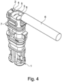
- einen Kontaktträger mit zwei angeschlossenen Kabeln und einer Schutzhülse,
- Figur 5:
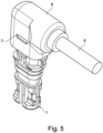
- einen verkabelten Kontaktträger mit Schutzhülse und zusätzlicher Dichtkappe und
- Figur 6:
- eine Sicht auf den Kontaktträger von oben gemäß der rechten Darstellung von
Figur 1 in vergrößerten Maßstab. - In den
Figuren 1 bis 6 ist, soweit im Einzelnen dargestellt, mit der Bezugsziffer 1 ein Kontaktträger bezeichnet, der ein Dichtelement 2 aufweist. Das Dichtelement 2 beinhaltet u.a. ein am Dichtelement fixiertes Festteil 3 und ein Rastteil 4, das mittels Sollbruchstellen 10 an dem Festteil 3 bzw. am Dichtelement 2 fixiert ist. Am Festteil 3 des Dichtelements 2 sind im Anschluss an die Sollbruchstellen 10 Nuten 12 eingearbeitet. Das Rastteil 4 weist Laschen 11 auf, die den Nuten 12 zugeordnet sind. Wird das Rastteil 4 in Richtung des Festteils 3 gemäßFigur 2 in die Darstellung gemäßFigur 3 verschoben, so werden zunächst die Sollbruchstellen 10 gelöst und das Rastteil 4 unter Führung der Laschen 11 und der Nuten 12 in Richtung Festteil 3 bewegt und mit diesem formschlüssig verbunden. - Werden vorher, wie in
Figur 4 dargestellt, Kabel 5 in den Kontaktträger 1 bzw. das Dichtelement 2 eingeführt, so wird der Außenmantel des Kabels 5 zwischen dem Festteil 3 und dem Rastteil 4 eingeklemmt und abgedichtet. - Eine zusätzliche Abdichtung des Bereichs Steckverbinder 1, Dichtelement 2 und Kabel(n) 5 wird durch eine Dichtkappe 9 bewirkt, die aufgespritzt sein kann oder mit Öffnungen 8 an Vorsprüngen 7 einrastet. Dichtlippen 13 an den Vorsprüngen 7 verbessern die Abdichtung. Die Vorsprünge 7 sind im Bereich des Dichtelements 2 an den Außenwänden des Festteils 3 und des Rastteils 4 angeordnet.
-
- 1.
- Kontaktträger
- 2.
- Dichtelement
- 3.
- Festteil
- 4.
- Rastteil
- 5.
- Kabel
- 6.
- Schutzhülse
- 7.
- Vorsprünge
- 8.
- Öffnungen
- 9.
- Dichtkappe
- 10.
- Sollbruchstellen
- 11.
- Laschen
- 12.
- Nuten
- 13.
- Dichtlippen
Claims (9)
- Steckverbinder, der einen aus Kunststoff gespritzten Kontaktträger (1) mit Kontaktkammern zur Aufnahme jeweils eines Kontaktpartners aufweist, wobei weiterhin ein auf jeweils einen Außenmantel zumindest eines Kabels (5), das aus dem Steckverbinder herausgeführt ist und dessen Ende seines elektrischen Leiters mit dem zugehörigen Kontaktpartner verbunden ist, wirkendes Dichtelement (2) vorgesehen ist, wobei das Dichtelement (2) von in einem Spritzgussverfahren verarbeiteten Kunststoff zusammen mit dem Kontaktträger (1) gebildet ist, dadurch gekennzeichnet, dass das Dichtelement (2) direkt an dem Kontaktträger (1) an zumindest einer Sollbruchstelle, vorzugsweise genau zwei Sollbruchstellen (10) angespritzt ist.
- Steckverbinder nach Anspruch 1, dadurch gekennzeichnet, dass das Dichtelement (2) ein am Kontaktträger (1) angeordnetes Festteil (3) und ein über die zumindest eine Sollbruchstelle (10) angelenktes Rastteil (4) aufweist.
- Steckverbinder nach einem der Ansprüche 1 oder 2, dadurch gekennzeichnet, dass zwei Sollbruchstellen (10) beidseitig zwischen dem Festteil (3) und dem Rastteil (4) vorgesehen sind.
- Steckverbinder nach einem der Ansprüche 1 bis 3, dadurch gekennzeichnet, dass die Sollbruchstellen (10) in Längsrichtung zum Kontaktträgers (1) ausgerichtet sind und dass das Rastteil (4) durch eine Querbewegung zum Kontaktträger (1) zur Abdichtung zumindest eines Kabels (5) verschiebbar ist.
- Steckverbinder nach einem der vorhergehenden Ansprüche, dadurch gekennzeichnet, dass das Rastteil (4) seitliche Laschen (11) aufweist, die Nuten (12) am Festteil (3) zugeordnet sind.
- Steckverbinder nach einem der vorhergehenden Ansprüche, dadurch gekennzeichnet, dass an den Laschen (11) und im Bereich der Nuten (12) Rasthaken und/oder Rastösen angeordnet sind.
- Steckverbinder nach einem der vorhergehenden Ansprüche, dadurch gekennzeichnet, dass an dem Festteil (3) und dem Rastteil (4), vorzugsweise an deren Außenflächen, Vorsprünge (7) vorgesehen sind, die als Führungselemente für eine umspritzte Dichtkappe (9) oder als Rastkörper für Öffnungen (8) an der Dichtkappe (9) dienen.
- Steckverbinder nach einem der vorhergehenden Ansprüche, dadurch gekennzeichnet, dass die Vorsprünge (7) umlaufende Dichtlippen (13) aufweisen.
- Verfahren zur Herstellung eines Steckverbinders, vorzugsweise eines Steckverbinders nach einem der vorhergehenden Ansprüche, der einen aus Kunststoff gespritzten Kontaktträger (1) mit Kontaktkammern zur Aufnahme jeweils eines Kontaktpartners aufweist, wobei weiterhin ein auf jeweils einen Außenmantel zumindest eines Kabels (5), das aus dem Steckverbinder herausgeführt ist und dessen Ende seines elektrischen Leiters mit dem zugehörigen Kontaktpartner verbunden ist, wirkendes Dichtelement (2) vorgesehen ist, wobei das Dichtelement (2) ebenfalls in einem Spritzgussverfahren aus Kunststoff hergestellt und nach seiner Herstellung an dem Kontaktträger (1) angefügt wird, dadurch gekennzeichnet, dass das Dichtelement (2) direkt an dem Kontaktträger (1) an zumindest einer Sollbruchstelle, vorzugsweise genau zwei Sollbruchstellen (10) angespritzt ist, wobei das Dichtelement (2) an dem Außenmantel des Kabels (5) zur Anlage kommt, wenn die Sollbruchstelle (10) durchtrennt worden ist.
Applications Claiming Priority (2)
| Application Number | Priority Date | Filing Date | Title |
|---|---|---|---|
| DE102018118481 | 2018-07-31 | ||
| PCT/EP2019/070602 WO2020025661A1 (de) | 2018-07-31 | 2019-07-31 | Verbesserte abdichtung der kontaktkammern gegen spritzgussmaterial (kunststoff) während des umspritzprozesses bei der herstellung eines steckverbinders |
Publications (2)
| Publication Number | Publication Date |
|---|---|
| EP3830909A1 EP3830909A1 (de) | 2021-06-09 |
| EP3830909B1 true EP3830909B1 (de) | 2024-06-26 |
Family
ID=67514640
Family Applications (1)
| Application Number | Title | Priority Date | Filing Date |
|---|---|---|---|
| EP19748806.7A Active EP3830909B1 (de) | 2018-07-31 | 2019-07-31 | Verbesserte abdichtung der kontaktkammern gegen spritzgussmaterial (kunststoff) während des umspritzprozesses bei der herstellung eines steckverbinders |
Country Status (6)
| Country | Link |
|---|---|
| US (1) | US11495911B2 (de) |
| EP (1) | EP3830909B1 (de) |
| CN (1) | CN112514172B (de) |
| DE (1) | DE102019120645A1 (de) |
| ES (1) | ES2985586T3 (de) |
| WO (1) | WO2020025661A1 (de) |
Citations (4)
| Publication number | Priority date | Publication date | Assignee | Title |
|---|---|---|---|---|
| US5586916A (en) * | 1994-04-15 | 1996-12-24 | Yazaki Corporation | Waterproof cover for connector |
| US5601449A (en) * | 1993-10-25 | 1997-02-11 | Yazaki Corporation | Rear holder cover of waterproof connector |
| US6464532B1 (en) * | 2000-09-14 | 2002-10-15 | Amp Deutschland Gmbh | Connector for a flat foil conductor |
| EP1699116A2 (de) * | 2005-03-02 | 2006-09-06 | Hirschmann Automotive GmbH | Steckverbinder mit einer Crimp-Abdichtung und/oder einer Kabelhalterung |
Family Cites Families (6)
| Publication number | Priority date | Publication date | Assignee | Title |
|---|---|---|---|---|
| ATE251348T1 (de) * | 2000-07-29 | 2003-10-15 | Whitaker Corp | Elektrischer steckverbinder sowie gehäuse für einen solchen elektrischen steckverbinder |
| EP2105996A1 (de) * | 2008-03-25 | 2009-09-30 | Esbe Ab | Gehäuse für Stecker und Kabel |
| CN101499569B (zh) * | 2008-10-21 | 2012-05-23 | 伸铭电子(东莞)有限公司 | 电子通信产品的电连接器及制造工艺 |
| WO2012062855A1 (de) | 2010-11-12 | 2012-05-18 | Hirschmann Automotive Gmbh | Abdichtung der kontaktkammern gegen spritzmaterial (kunststoff) während dem umspritzprozess |
| EP3485539B1 (de) * | 2016-07-15 | 2022-06-29 | Hirschmann Automotive GmbH | Hochtemperaturbeständiger steckverbinder für einen klopfsensor einer brennkraftmaschine |
| WO2018215026A1 (de) * | 2017-05-23 | 2018-11-29 | Fep Fahrzeugelektrik Pirna Gmbh & Co. Kg | Kontaktträger zur aufnahme und fixierung von kontaktelementen |
-
2019
- 2019-07-31 WO PCT/EP2019/070602 patent/WO2020025661A1/de not_active Ceased
- 2019-07-31 EP EP19748806.7A patent/EP3830909B1/de active Active
- 2019-07-31 ES ES19748806T patent/ES2985586T3/es active Active
- 2019-07-31 DE DE102019120645.6A patent/DE102019120645A1/de not_active Ceased
- 2019-07-31 CN CN201980050626.4A patent/CN112514172B/zh active Active
- 2019-07-31 US US17/260,657 patent/US11495911B2/en active Active
Patent Citations (4)
| Publication number | Priority date | Publication date | Assignee | Title |
|---|---|---|---|---|
| US5601449A (en) * | 1993-10-25 | 1997-02-11 | Yazaki Corporation | Rear holder cover of waterproof connector |
| US5586916A (en) * | 1994-04-15 | 1996-12-24 | Yazaki Corporation | Waterproof cover for connector |
| US6464532B1 (en) * | 2000-09-14 | 2002-10-15 | Amp Deutschland Gmbh | Connector for a flat foil conductor |
| EP1699116A2 (de) * | 2005-03-02 | 2006-09-06 | Hirschmann Automotive GmbH | Steckverbinder mit einer Crimp-Abdichtung und/oder einer Kabelhalterung |
Also Published As
| Publication number | Publication date |
|---|---|
| CN112514172B (zh) | 2023-02-28 |
| ES2985586T3 (es) | 2024-11-06 |
| US20210265770A1 (en) | 2021-08-26 |
| CN112514172A (zh) | 2021-03-16 |
| WO2020025661A1 (de) | 2020-02-06 |
| EP3830909A1 (de) | 2021-06-09 |
| US11495911B2 (en) | 2022-11-08 |
| DE102019120645A1 (de) | 2020-02-06 |
Similar Documents
| Publication | Publication Date | Title |
|---|---|---|
| EP3453080B1 (de) | Umspritzter steckverbinder | |
| EP1703596B1 (de) | Steckverbinder mit Distanzteil zwischen zumindest zwei Flachbandleitungen zwecks Abdichtung gegen Spritzgussmasse und Feuchtigkeit | |
| DE10305381A1 (de) | Verbindungsanordnung und Herstellverfahren für eine Verbindungsanordnung | |
| DE102010015092A1 (de) | Vorrichtungsverbinderherstellungsverfahren, Vorrichtungsverbinder und Formstruktur dafür | |
| EP3622588B1 (de) | Verfahren zur montage eines steckers an einer mehradrigen mantelleitung sowie elektrischer stecker | |
| EP2979329B1 (de) | Fluiddichte kontaktdurchführung | |
| DE10350763A1 (de) | Koaxialkabel mit Winkelsteckverbindung | |
| EP3485539B1 (de) | Hochtemperaturbeständiger steckverbinder für einen klopfsensor einer brennkraftmaschine | |
| EP2220510B1 (de) | Verfahren zur herstellung eines magnetfeldsensors und nach dem verfahren hergestellter sensor | |
| EP1699116B1 (de) | Steckverbinder mit einer Crimp-Abdichtung und/oder einer Kabelhalterung | |
| EP2896093A1 (de) | Elektrischer kontaktstecker sowie steckergehäuse | |
| EP2638603B1 (de) | Abdichtung der kontaktkammern gegen spritzmaterial (kunststoff) während des umspritzprozesses | |
| DE202016102392U1 (de) | Umspritzadapter | |
| DE102005009442A1 (de) | Steckverbinder mit einer Crimp-Abdichtung und/oder einer Kabelhalterung | |
| DE10021672B4 (de) | Hermetisch verkapselter Sensor und Verfahren zu seiner Herstellung | |
| DE10054714A1 (de) | Verfahren zum Abdichten eines Kabels in/an einem Kabeldurchführungskanal sowie ein Kabeldurchführungskanal | |
| DE102006036139A1 (de) | Spritzgießanordnung und Verfahren zum Anspritzen eines Formteils und Verwendung einer Spritzgießanordnung | |
| EP3185367A1 (de) | Wasserdichtes konfektioniertes kabel mit steckverbinder | |
| WO2020025661A1 (de) | Verbesserte abdichtung der kontaktkammern gegen spritzgussmaterial (kunststoff) während des umspritzprozesses bei der herstellung eines steckverbinders | |
| EP3192131A1 (de) | Träger für ein sensorelement, bauteilgruppe und drehzahlsensor | |
| DE19748044A1 (de) | Kupplungselement eines elektrischen Kabels | |
| DE102014109270A1 (de) | Leitungsfixierung und Verfahren zum Fixieren einer elektrischen Leitung an einem Stecker | |
| EP0380042A2 (de) | Durchführungstülle | |
| EP3704774B1 (de) | Bauteil mit einem gehäuse, einem kabelstrang und eine zugentlastung | |
| DE19904276B4 (de) | Anschlußkasten für elektrische Kabel |
Legal Events
| Date | Code | Title | Description |
|---|---|---|---|
| STAA | Information on the status of an ep patent application or granted ep patent |
Free format text: STATUS: UNKNOWN |
|
| STAA | Information on the status of an ep patent application or granted ep patent |
Free format text: STATUS: THE INTERNATIONAL PUBLICATION HAS BEEN MADE |
|
| PUAI | Public reference made under article 153(3) epc to a published international application that has entered the european phase |
Free format text: ORIGINAL CODE: 0009012 |
|
| STAA | Information on the status of an ep patent application or granted ep patent |
Free format text: STATUS: REQUEST FOR EXAMINATION WAS MADE |
|
| 17P | Request for examination filed |
Effective date: 20210115 |
|
| AK | Designated contracting states |
Kind code of ref document: A1 Designated state(s): AL AT BE BG CH CY CZ DE DK EE ES FI FR GB GR HR HU IE IS IT LI LT LU LV MC MK MT NL NO PL PT RO RS SE SI SK SM TR |
|
| DAV | Request for validation of the european patent (deleted) | ||
| DAX | Request for extension of the european patent (deleted) | ||
| STAA | Information on the status of an ep patent application or granted ep patent |
Free format text: STATUS: EXAMINATION IS IN PROGRESS |
|
| 17Q | First examination report despatched |
Effective date: 20230209 |
|
| GRAP | Despatch of communication of intention to grant a patent |
Free format text: ORIGINAL CODE: EPIDOSNIGR1 |
|
| STAA | Information on the status of an ep patent application or granted ep patent |
Free format text: STATUS: GRANT OF PATENT IS INTENDED |
|
| INTG | Intention to grant announced |
Effective date: 20240327 |
|
| RIN1 | Information on inventor provided before grant (corrected) |
Inventor name: TOMASINI, LUKAS Inventor name: JAEGER, GUENTER |
|
| GRAS | Grant fee paid |
Free format text: ORIGINAL CODE: EPIDOSNIGR3 |
|
| GRAA | (expected) grant |
Free format text: ORIGINAL CODE: 0009210 |
|
| STAA | Information on the status of an ep patent application or granted ep patent |
Free format text: STATUS: THE PATENT HAS BEEN GRANTED |
|
| AK | Designated contracting states |
Kind code of ref document: B1 Designated state(s): AL AT BE BG CH CY CZ DE DK EE ES FI FR GB GR HR HU IE IS IT LI LT LU LV MC MK MT NL NO PL PT RO RS SE SI SK SM TR |
|
| REG | Reference to a national code |
Ref country code: GB Ref legal event code: FG4D Free format text: NOT ENGLISH |
|
| REG | Reference to a national code |
Ref country code: CH Ref legal event code: EP |
|
| REG | Reference to a national code |
Ref country code: DE Ref legal event code: R096 Ref document number: 502019011521 Country of ref document: DE |
|
| PG25 | Lapsed in a contracting state [announced via postgrant information from national office to epo] |
Ref country code: BG Free format text: LAPSE BECAUSE OF FAILURE TO SUBMIT A TRANSLATION OF THE DESCRIPTION OR TO PAY THE FEE WITHIN THE PRESCRIBED TIME-LIMIT Effective date: 20240626 |
|
| PG25 | Lapsed in a contracting state [announced via postgrant information from national office to epo] |
Ref country code: FI Free format text: LAPSE BECAUSE OF FAILURE TO SUBMIT A TRANSLATION OF THE DESCRIPTION OR TO PAY THE FEE WITHIN THE PRESCRIBED TIME-LIMIT Effective date: 20240626 Ref country code: HR Free format text: LAPSE BECAUSE OF FAILURE TO SUBMIT A TRANSLATION OF THE DESCRIPTION OR TO PAY THE FEE WITHIN THE PRESCRIBED TIME-LIMIT Effective date: 20240626 |
|
| REG | Reference to a national code |
Ref country code: LT Ref legal event code: MG9D |
|
| PG25 | Lapsed in a contracting state [announced via postgrant information from national office to epo] |
Ref country code: GR Free format text: LAPSE BECAUSE OF FAILURE TO SUBMIT A TRANSLATION OF THE DESCRIPTION OR TO PAY THE FEE WITHIN THE PRESCRIBED TIME-LIMIT Effective date: 20240927 |
|
| PGFP | Annual fee paid to national office [announced via postgrant information from national office to epo] |
Ref country code: GB Payment date: 20240725 Year of fee payment: 6 |
|
| PGFP | Annual fee paid to national office [announced via postgrant information from national office to epo] |
Ref country code: FR Payment date: 20240820 Year of fee payment: 6 |
|
| PGFP | Annual fee paid to national office [announced via postgrant information from national office to epo] |
Ref country code: ES Payment date: 20240829 Year of fee payment: 6 |
|
| PG25 | Lapsed in a contracting state [announced via postgrant information from national office to epo] |
Ref country code: LV Free format text: LAPSE BECAUSE OF FAILURE TO SUBMIT A TRANSLATION OF THE DESCRIPTION OR TO PAY THE FEE WITHIN THE PRESCRIBED TIME-LIMIT Effective date: 20240626 |
|
| REG | Reference to a national code |
Ref country code: NL Ref legal event code: MP Effective date: 20240626 |
|
| PG25 | Lapsed in a contracting state [announced via postgrant information from national office to epo] |
Ref country code: NO Free format text: LAPSE BECAUSE OF FAILURE TO SUBMIT A TRANSLATION OF THE DESCRIPTION OR TO PAY THE FEE WITHIN THE PRESCRIBED TIME-LIMIT Effective date: 20240926 Ref country code: LV Free format text: LAPSE BECAUSE OF FAILURE TO SUBMIT A TRANSLATION OF THE DESCRIPTION OR TO PAY THE FEE WITHIN THE PRESCRIBED TIME-LIMIT Effective date: 20240626 Ref country code: HR Free format text: LAPSE BECAUSE OF FAILURE TO SUBMIT A TRANSLATION OF THE DESCRIPTION OR TO PAY THE FEE WITHIN THE PRESCRIBED TIME-LIMIT Effective date: 20240626 Ref country code: GR Free format text: LAPSE BECAUSE OF FAILURE TO SUBMIT A TRANSLATION OF THE DESCRIPTION OR TO PAY THE FEE WITHIN THE PRESCRIBED TIME-LIMIT Effective date: 20240927 Ref country code: FI Free format text: LAPSE BECAUSE OF FAILURE TO SUBMIT A TRANSLATION OF THE DESCRIPTION OR TO PAY THE FEE WITHIN THE PRESCRIBED TIME-LIMIT Effective date: 20240626 Ref country code: BG Free format text: LAPSE BECAUSE OF FAILURE TO SUBMIT A TRANSLATION OF THE DESCRIPTION OR TO PAY THE FEE WITHIN THE PRESCRIBED TIME-LIMIT Effective date: 20240626 Ref country code: RS Free format text: LAPSE BECAUSE OF FAILURE TO SUBMIT A TRANSLATION OF THE DESCRIPTION OR TO PAY THE FEE WITHIN THE PRESCRIBED TIME-LIMIT Effective date: 20240926 |
|
| REG | Reference to a national code |
Ref country code: ES Ref legal event code: FG2A Ref document number: 2985586 Country of ref document: ES Kind code of ref document: T3 Effective date: 20241106 |
|
| PG25 | Lapsed in a contracting state [announced via postgrant information from national office to epo] |
Ref country code: NL Free format text: LAPSE BECAUSE OF FAILURE TO SUBMIT A TRANSLATION OF THE DESCRIPTION OR TO PAY THE FEE WITHIN THE PRESCRIBED TIME-LIMIT Effective date: 20240626 |
|
| PG25 | Lapsed in a contracting state [announced via postgrant information from national office to epo] |
Ref country code: NL Free format text: LAPSE BECAUSE OF FAILURE TO SUBMIT A TRANSLATION OF THE DESCRIPTION OR TO PAY THE FEE WITHIN THE PRESCRIBED TIME-LIMIT Effective date: 20240626 |
|
| PG25 | Lapsed in a contracting state [announced via postgrant information from national office to epo] |
Ref country code: PT Free format text: LAPSE BECAUSE OF FAILURE TO SUBMIT A TRANSLATION OF THE DESCRIPTION OR TO PAY THE FEE WITHIN THE PRESCRIBED TIME-LIMIT Effective date: 20241028 |
|
| PG25 | Lapsed in a contracting state [announced via postgrant information from national office to epo] |
Ref country code: PT Free format text: LAPSE BECAUSE OF FAILURE TO SUBMIT A TRANSLATION OF THE DESCRIPTION OR TO PAY THE FEE WITHIN THE PRESCRIBED TIME-LIMIT Effective date: 20241028 |
|
| PG25 | Lapsed in a contracting state [announced via postgrant information from national office to epo] |
Ref country code: PL Free format text: LAPSE BECAUSE OF FAILURE TO SUBMIT A TRANSLATION OF THE DESCRIPTION OR TO PAY THE FEE WITHIN THE PRESCRIBED TIME-LIMIT Effective date: 20240626 |
|
| PG25 | Lapsed in a contracting state [announced via postgrant information from national office to epo] |
Ref country code: EE Free format text: LAPSE BECAUSE OF FAILURE TO SUBMIT A TRANSLATION OF THE DESCRIPTION OR TO PAY THE FEE WITHIN THE PRESCRIBED TIME-LIMIT Effective date: 20240626 |
|
| PG25 | Lapsed in a contracting state [announced via postgrant information from national office to epo] |
Ref country code: IS Free format text: LAPSE BECAUSE OF FAILURE TO SUBMIT A TRANSLATION OF THE DESCRIPTION OR TO PAY THE FEE WITHIN THE PRESCRIBED TIME-LIMIT Effective date: 20241026 |
|
| PG25 | Lapsed in a contracting state [announced via postgrant information from national office to epo] |
Ref country code: CZ Free format text: LAPSE BECAUSE OF FAILURE TO SUBMIT A TRANSLATION OF THE DESCRIPTION OR TO PAY THE FEE WITHIN THE PRESCRIBED TIME-LIMIT Effective date: 20240626 |
|
| PG25 | Lapsed in a contracting state [announced via postgrant information from national office to epo] |
Ref country code: RO Free format text: LAPSE BECAUSE OF FAILURE TO SUBMIT A TRANSLATION OF THE DESCRIPTION OR TO PAY THE FEE WITHIN THE PRESCRIBED TIME-LIMIT Effective date: 20240626 Ref country code: SK Free format text: LAPSE BECAUSE OF FAILURE TO SUBMIT A TRANSLATION OF THE DESCRIPTION OR TO PAY THE FEE WITHIN THE PRESCRIBED TIME-LIMIT Effective date: 20240626 |
|
| PG25 | Lapsed in a contracting state [announced via postgrant information from national office to epo] |
Ref country code: SM Free format text: LAPSE BECAUSE OF FAILURE TO SUBMIT A TRANSLATION OF THE DESCRIPTION OR TO PAY THE FEE WITHIN THE PRESCRIBED TIME-LIMIT Effective date: 20240626 |
|
| PG25 | Lapsed in a contracting state [announced via postgrant information from national office to epo] |
Ref country code: SM Free format text: LAPSE BECAUSE OF FAILURE TO SUBMIT A TRANSLATION OF THE DESCRIPTION OR TO PAY THE FEE WITHIN THE PRESCRIBED TIME-LIMIT Effective date: 20240626 Ref country code: SK Free format text: LAPSE BECAUSE OF FAILURE TO SUBMIT A TRANSLATION OF THE DESCRIPTION OR TO PAY THE FEE WITHIN THE PRESCRIBED TIME-LIMIT Effective date: 20240626 Ref country code: RO Free format text: LAPSE BECAUSE OF FAILURE TO SUBMIT A TRANSLATION OF THE DESCRIPTION OR TO PAY THE FEE WITHIN THE PRESCRIBED TIME-LIMIT Effective date: 20240626 Ref country code: PL Free format text: LAPSE BECAUSE OF FAILURE TO SUBMIT A TRANSLATION OF THE DESCRIPTION OR TO PAY THE FEE WITHIN THE PRESCRIBED TIME-LIMIT Effective date: 20240626 Ref country code: IS Free format text: LAPSE BECAUSE OF FAILURE TO SUBMIT A TRANSLATION OF THE DESCRIPTION OR TO PAY THE FEE WITHIN THE PRESCRIBED TIME-LIMIT Effective date: 20241026 Ref country code: EE Free format text: LAPSE BECAUSE OF FAILURE TO SUBMIT A TRANSLATION OF THE DESCRIPTION OR TO PAY THE FEE WITHIN THE PRESCRIBED TIME-LIMIT Effective date: 20240626 Ref country code: CZ Free format text: LAPSE BECAUSE OF FAILURE TO SUBMIT A TRANSLATION OF THE DESCRIPTION OR TO PAY THE FEE WITHIN THE PRESCRIBED TIME-LIMIT Effective date: 20240626 |
|
| REG | Reference to a national code |
Ref country code: CH Ref legal event code: PL |
|
| PG25 | Lapsed in a contracting state [announced via postgrant information from national office to epo] |
Ref country code: LU Free format text: LAPSE BECAUSE OF NON-PAYMENT OF DUE FEES Effective date: 20240731 |
|
| PG25 | Lapsed in a contracting state [announced via postgrant information from national office to epo] |
Ref country code: MC Free format text: LAPSE BECAUSE OF FAILURE TO SUBMIT A TRANSLATION OF THE DESCRIPTION OR TO PAY THE FEE WITHIN THE PRESCRIBED TIME-LIMIT Effective date: 20240626 |
|
| REG | Reference to a national code |
Ref country code: DE Ref legal event code: R097 Ref document number: 502019011521 Country of ref document: DE |
|
| PG25 | Lapsed in a contracting state [announced via postgrant information from national office to epo] |
Ref country code: MC Free format text: LAPSE BECAUSE OF FAILURE TO SUBMIT A TRANSLATION OF THE DESCRIPTION OR TO PAY THE FEE WITHIN THE PRESCRIBED TIME-LIMIT Effective date: 20240626 Ref country code: LU Free format text: LAPSE BECAUSE OF NON-PAYMENT OF DUE FEES Effective date: 20240731 |
|
| PG25 | Lapsed in a contracting state [announced via postgrant information from national office to epo] |
Ref country code: DK Free format text: LAPSE BECAUSE OF FAILURE TO SUBMIT A TRANSLATION OF THE DESCRIPTION OR TO PAY THE FEE WITHIN THE PRESCRIBED TIME-LIMIT Effective date: 20240626 |
|
| PG25 | Lapsed in a contracting state [announced via postgrant information from national office to epo] |
Ref country code: BE Free format text: LAPSE BECAUSE OF NON-PAYMENT OF DUE FEES Effective date: 20240731 Ref country code: CH Free format text: LAPSE BECAUSE OF NON-PAYMENT OF DUE FEES Effective date: 20240731 |
|
| PLBE | No opposition filed within time limit |
Free format text: ORIGINAL CODE: 0009261 |
|
| STAA | Information on the status of an ep patent application or granted ep patent |
Free format text: STATUS: NO OPPOSITION FILED WITHIN TIME LIMIT |
|
| 26N | No opposition filed |
Effective date: 20250327 |
|
| REG | Reference to a national code |
Ref country code: BE Ref legal event code: MM Effective date: 20240731 |
|
| PG25 | Lapsed in a contracting state [announced via postgrant information from national office to epo] |
Ref country code: IT Free format text: LAPSE BECAUSE OF NON-PAYMENT OF DUE FEES Effective date: 20240731 |
|
| PG25 | Lapsed in a contracting state [announced via postgrant information from national office to epo] |
Ref country code: IE Free format text: LAPSE BECAUSE OF NON-PAYMENT OF DUE FEES Effective date: 20240731 |
|
| PG25 | Lapsed in a contracting state [announced via postgrant information from national office to epo] |
Ref country code: SE Free format text: LAPSE BECAUSE OF FAILURE TO SUBMIT A TRANSLATION OF THE DESCRIPTION OR TO PAY THE FEE WITHIN THE PRESCRIBED TIME-LIMIT Effective date: 20240626 |
|
| REG | Reference to a national code |
Ref country code: AT Ref legal event code: MM01 Ref document number: 1698499 Country of ref document: AT Kind code of ref document: T Effective date: 20240731 |
|
| PGFP | Annual fee paid to national office [announced via postgrant information from national office to epo] |
Ref country code: DE Payment date: 20250722 Year of fee payment: 7 |
|
| PG25 | Lapsed in a contracting state [announced via postgrant information from national office to epo] |
Ref country code: AT Free format text: LAPSE BECAUSE OF NON-PAYMENT OF DUE FEES Effective date: 20240731 |
|
| PG25 | Lapsed in a contracting state [announced via postgrant information from national office to epo] |
Ref country code: CY Free format text: LAPSE BECAUSE OF FAILURE TO SUBMIT A TRANSLATION OF THE DESCRIPTION OR TO PAY THE FEE WITHIN THE PRESCRIBED TIME-LIMIT; INVALID AB INITIO Effective date: 20190731 |
|
| PG25 | Lapsed in a contracting state [announced via postgrant information from national office to epo] |
Ref country code: HU Free format text: LAPSE BECAUSE OF FAILURE TO SUBMIT A TRANSLATION OF THE DESCRIPTION OR TO PAY THE FEE WITHIN THE PRESCRIBED TIME-LIMIT; INVALID AB INITIO Effective date: 20190731 |
|
| GBPC | Gb: european patent ceased through non-payment of renewal fee |
Effective date: 20250731 |
|
| PG25 | Lapsed in a contracting state [announced via postgrant information from national office to epo] |
Ref country code: GB Free format text: LAPSE BECAUSE OF NON-PAYMENT OF DUE FEES Effective date: 20250731 |
|
| PG25 | Lapsed in a contracting state [announced via postgrant information from national office to epo] |
Ref country code: FR Free format text: LAPSE BECAUSE OF NON-PAYMENT OF DUE FEES Effective date: 20250731 |