EP3828057A1 - Mit lenkfunktion ausgestattete nabeneinheit - Google Patents
Mit lenkfunktion ausgestattete nabeneinheit Download PDFInfo
- Publication number
- EP3828057A1 EP3828057A1 EP20209034.6A EP20209034A EP3828057A1 EP 3828057 A1 EP3828057 A1 EP 3828057A1 EP 20209034 A EP20209034 A EP 20209034A EP 3828057 A1 EP3828057 A1 EP 3828057A1
- Authority
- EP
- European Patent Office
- Prior art keywords
- steering
- equipped hub
- turning shaft
- suspension device
- steering actuator
- Prior art date
- Legal status (The legal status is an assumption and is not a legal conclusion. Google has not performed a legal analysis and makes no representation as to the accuracy of the status listed.)
- Pending
Links
Images


Classifications
-
- B—PERFORMING OPERATIONS; TRANSPORTING
- B62—LAND VEHICLES FOR TRAVELLING OTHERWISE THAN ON RAILS
- B62D—MOTOR VEHICLES; TRAILERS
- B62D5/00—Power-assisted or power-driven steering
- B62D5/04—Power-assisted or power-driven steering electrical, e.g. using an electric servo-motor connected to, or forming part of, the steering gear
- B62D5/0418—Electric motor acting on road wheel carriers
-
- B—PERFORMING OPERATIONS; TRANSPORTING
- B62—LAND VEHICLES FOR TRAVELLING OTHERWISE THAN ON RAILS
- B62D—MOTOR VEHICLES; TRAILERS
- B62D5/00—Power-assisted or power-driven steering
- B62D5/04—Power-assisted or power-driven steering electrical, e.g. using an electric servo-motor connected to, or forming part of, the steering gear
-
- B—PERFORMING OPERATIONS; TRANSPORTING
- B60—VEHICLES IN GENERAL
- B60B—VEHICLE WHEELS; CASTORS; AXLES FOR WHEELS OR CASTORS; INCREASING WHEEL ADHESION
- B60B27/00—Hubs
- B60B27/001—Hubs with roller-bearings
-
- B—PERFORMING OPERATIONS; TRANSPORTING
- B60—VEHICLES IN GENERAL
- B60B—VEHICLE WHEELS; CASTORS; AXLES FOR WHEELS OR CASTORS; INCREASING WHEEL ADHESION
- B60B27/00—Hubs
- B60B27/0047—Hubs characterised by functional integration of other elements
- B60B27/0052—Hubs characterised by functional integration of other elements the element being a brake disc
-
- B—PERFORMING OPERATIONS; TRANSPORTING
- B60—VEHICLES IN GENERAL
- B60G—VEHICLE SUSPENSION ARRANGEMENTS
- B60G21/00—Interconnection systems for two or more resiliently-suspended wheels, e.g. for stabilising a vehicle body with respect to acceleration, deceleration or centrifugal forces
- B60G21/02—Interconnection systems for two or more resiliently-suspended wheels, e.g. for stabilising a vehicle body with respect to acceleration, deceleration or centrifugal forces permanently interconnected
- B60G21/04—Interconnection systems for two or more resiliently-suspended wheels, e.g. for stabilising a vehicle body with respect to acceleration, deceleration or centrifugal forces permanently interconnected mechanically
- B60G21/05—Interconnection systems for two or more resiliently-suspended wheels, e.g. for stabilising a vehicle body with respect to acceleration, deceleration or centrifugal forces permanently interconnected mechanically between wheels on the same axle but on different sides of the vehicle, i.e. the left and right wheel suspensions being interconnected
- B60G21/051—Trailing arm twist beam axles
- B60G21/052—Mounting means therefor
-
- B—PERFORMING OPERATIONS; TRANSPORTING
- B60—VEHICLES IN GENERAL
- B60G—VEHICLE SUSPENSION ARRANGEMENTS
- B60G7/00—Pivoted suspension arms; Accessories thereof
- B60G7/006—Attaching arms to sprung or unsprung part of vehicle, characterised by comprising attachment means controlled by an external actuator, e.g. a fluid or electrical motor
-
- B—PERFORMING OPERATIONS; TRANSPORTING
- B62—LAND VEHICLES FOR TRAVELLING OTHERWISE THAN ON RAILS
- B62D—MOTOR VEHICLES; TRAILERS
- B62D5/00—Power-assisted or power-driven steering
- B62D5/04—Power-assisted or power-driven steering electrical, e.g. using an electric servo-motor connected to, or forming part of, the steering gear
- B62D5/0403—Power-assisted or power-driven steering electrical, e.g. using an electric servo-motor connected to, or forming part of, the steering gear characterised by constructional features, e.g. common housing for motor and gear box
-
- B—PERFORMING OPERATIONS; TRANSPORTING
- B62—LAND VEHICLES FOR TRAVELLING OTHERWISE THAN ON RAILS
- B62D—MOTOR VEHICLES; TRAILERS
- B62D5/00—Power-assisted or power-driven steering
- B62D5/04—Power-assisted or power-driven steering electrical, e.g. using an electric servo-motor connected to, or forming part of, the steering gear
- B62D5/0442—Conversion of rotational into longitudinal movement
- B62D5/0445—Screw drives
-
- B—PERFORMING OPERATIONS; TRANSPORTING
- B62—LAND VEHICLES FOR TRAVELLING OTHERWISE THAN ON RAILS
- B62D—MOTOR VEHICLES; TRAILERS
- B62D7/00—Steering linkage; Stub axles or their mountings
- B62D7/06—Steering linkage; Stub axles or their mountings for individually-pivoted wheels, e.g. on king-pins
- B62D7/14—Steering linkage; Stub axles or their mountings for individually-pivoted wheels, e.g. on king-pins the pivotal axes being situated in more than one plane transverse to the longitudinal centre line of the vehicle, e.g. all-wheel steering
- B62D7/146—Steering linkage; Stub axles or their mountings for individually-pivoted wheels, e.g. on king-pins the pivotal axes being situated in more than one plane transverse to the longitudinal centre line of the vehicle, e.g. all-wheel steering characterised by comprising means for steering by acting on the suspension system, e.g. on the mountings of the suspension arms
-
- B—PERFORMING OPERATIONS; TRANSPORTING
- B60—VEHICLES IN GENERAL
- B60G—VEHICLE SUSPENSION ARRANGEMENTS
- B60G2200/00—Indexing codes relating to suspension types
- B60G2200/20—Semi-rigid axle suspensions
-
- B—PERFORMING OPERATIONS; TRANSPORTING
- B60—VEHICLES IN GENERAL
- B60G—VEHICLE SUSPENSION ARRANGEMENTS
- B60G2200/00—Indexing codes relating to suspension types
- B60G2200/40—Indexing codes relating to the wheels in the suspensions
- B60G2200/44—Indexing codes relating to the wheels in the suspensions steerable
-
- B—PERFORMING OPERATIONS; TRANSPORTING
- B60—VEHICLES IN GENERAL
- B60G—VEHICLE SUSPENSION ARRANGEMENTS
- B60G2204/00—Indexing codes related to suspensions per se or to auxiliary parts
- B60G2204/40—Auxiliary suspension parts; Adjustment of suspensions
- B60G2204/418—Bearings, e.g. ball or roller bearings
-
- B—PERFORMING OPERATIONS; TRANSPORTING
- B60—VEHICLES IN GENERAL
- B60G—VEHICLE SUSPENSION ARRANGEMENTS
- B60G2204/00—Indexing codes related to suspensions per se or to auxiliary parts
- B60G2204/40—Auxiliary suspension parts; Adjustment of suspensions
- B60G2204/43—Fittings, brackets or knuckles
-
- B—PERFORMING OPERATIONS; TRANSPORTING
- B60—VEHICLES IN GENERAL
- B60G—VEHICLE SUSPENSION ARRANGEMENTS
- B60G2206/00—Indexing codes related to the manufacturing of suspensions: constructional features, the materials used, procedures or tools
- B60G2206/01—Constructional features of suspension elements, e.g. arms, dampers, springs
- B60G2206/20—Constructional features of semi-rigid axles, e.g. twist beam type axles
-
- B—PERFORMING OPERATIONS; TRANSPORTING
- B60—VEHICLES IN GENERAL
- B60G—VEHICLE SUSPENSION ARRANGEMENTS
- B60G2206/00—Indexing codes related to the manufacturing of suspensions: constructional features, the materials used, procedures or tools
- B60G2206/01—Constructional features of suspension elements, e.g. arms, dampers, springs
- B60G2206/50—Constructional features of wheel supports or knuckles, e.g. steering knuckles, spindle attachments
-
- B—PERFORMING OPERATIONS; TRANSPORTING
- B60—VEHICLES IN GENERAL
- B60G—VEHICLE SUSPENSION ARRANGEMENTS
- B60G2800/00—Indexing codes relating to the type of movement or to the condition of the vehicle and to the end result to be achieved by the control action
- B60G2800/90—System Controller type
- B60G2800/96—ASC - Assisted or power Steering control
- B60G2800/962—Four-wheel steering
-
- B—PERFORMING OPERATIONS; TRANSPORTING
- B62—LAND VEHICLES FOR TRAVELLING OTHERWISE THAN ON RAILS
- B62D—MOTOR VEHICLES; TRAILERS
- B62D7/00—Steering linkage; Stub axles or their mountings
- B62D7/06—Steering linkage; Stub axles or their mountings for individually-pivoted wheels, e.g. on king-pins
- B62D7/14—Steering linkage; Stub axles or their mountings for individually-pivoted wheels, e.g. on king-pins the pivotal axes being situated in more than one plane transverse to the longitudinal centre line of the vehicle, e.g. all-wheel steering
- B62D7/15—Steering linkage; Stub axles or their mountings for individually-pivoted wheels, e.g. on king-pins the pivotal axes being situated in more than one plane transverse to the longitudinal centre line of the vehicle, e.g. all-wheel steering characterised by means varying the ratio between the steering angles of the steered wheels
- B62D7/1581—Steering linkage; Stub axles or their mountings for individually-pivoted wheels, e.g. on king-pins the pivotal axes being situated in more than one plane transverse to the longitudinal centre line of the vehicle, e.g. all-wheel steering characterised by means varying the ratio between the steering angles of the steered wheels characterised by comprising an electrical interconnecting system between the steering control means of the different axles
Definitions
- the present invention relates to a steering function-equipped hub unit having a function of steering a rear wheel carried by a torsion beam suspension device and to a technology of controlling left and right rear wheels to appropriate steering angles according to traveling conditions so as to improve fuel economy, traveling stability and safety.
- Patent Document 1 employs a steering actuator attached to an unsprung site (or a torsion beam suspension device).
- the steering actuator is disposed along a trailing arm extending in a front-rear direction of a vehicle so to avoid interference with other components such as a fuel tank or a silencer, and the steering actuator is disposed near an attachment part to a vehicle body so as to suppress change of toe angles in association with up-and-down motion of tires.
- Patent Document 1 requires a large power to steer the tires while drawing them because a king pin shaft (a turning shaft) is located away from a center of a ground contact surface of each tire. Also, the structure has large tire houses because the tires have large turning paths.
- a steering function-equipped hub unit (see Patent Document 2 above) that has been proposed by the present applicant can be mounted even on a rigid axle such as a torsion beam suspension device and is capable of independently controlling each steering angle.
- a coil spring and a shock absorber are disposed on the back of a hub bearing of the steering function-equipped hub unit.
- the steering function-equipped hub unit is increased in the size and therefore the weight for this reason, that may affect ride quality of the vehicle.
- the steering actuator would have an increased size, making it difficult to mount the steering function-equipped hub unit in the vehicle.
- a torsion beam suspension device which is applied to rear wheels of a vehicle is rotationally supported by a vehicle body at a rotation support part and bounds/rebounds in conjunction with the motions of the vehicle.
- the torsion beam suspension device is an unsprung component, and weight increase of an unsprung component affects ride quality of the vehicle. Also, where a heavy object is attached away from the rotation support part, a moment of inertia increases, which may lead to deterioration of the ride quality.
- the vehicle has components such as a shock absorber for a suspension device or a muffler near the rear wheels and thus has a limited space to dispose the steering actuator in that area. Accordingly, the steering actuator would interfere with other components so that it is difficult to easily mount the steering function-equipped hub unit in the vehicle.
- An object of the present invention is to provide a steering function-equipped hub unit capable of adjusting a steering angle to a desired angle, preventing deterioration of ride comfort of a vehicle, and being easily mounted in the vehicle without involving a significant structural change to the vehicle.
- a steering function-equipped hub unit of the present invention is configured to steer a rear wheel of a vehicle, which is configured to be supported by a suspension device including a torsion beam and a pair of trailing arms.
- the steering function-equipped hub unit includes:
- the term "separate" means that the steering actuator and the unit support member are constituted by distinct elements that can be detached from each other.
- the rotation support part is a constituent of the suspension device and is supported so as to be rotatable with respect to the vehicle body about an axis in a vehicle widthwise direction.
- the turning shaft-equipped hub bearing which supports the rear wheel can be freely rotated about the turning axis by driving the steering actuator.
- the steering actuator is separate from the unit support member so that the steering actuator having an increased size can be disposed without causing interference with existing components.
- a desired steering angle can be achieved.
- the steering actuator that is separate from the unit support member is attached to the suspension device between the rotation support part of the suspension device and the turning shaft-equipped hub bearing so that it is possible to suppress increase in the moment of inertia of the suspension device and to prevent deterioration of the ride quality during bounding or the like in comparison with a conventional configuration in which the unit support member and the steering actuator are integrally provided.
- the steering actuator is a separate component from the unit support member, the mechanical elements have a greater choice of arrangements, making it possible to easily dispose the steering function-equipped hub unit in the vehicle without losing a space for the existing components such as a shock absorber. Therefore, the steering function-equipped hub unit can be easily mounted in the vehicle without involving a significant structural change to the vehicle.
- the steering actuator may include a linear motion mechanism main body and a linear motion output part capable of advancing and retreating with respect to the linear motion mechanism main body and configured to provide a steering force to an outer ring of the turning shaft-equipped hub bearing, and the linear motion mechanism main body may be attached to the suspension device such that the linear motion output part advances and retreats in a left-right direction of the vehicle body.
- the linear motion mechanism main body is attached to the suspension device such that the linear motion output part advances and retreats in the left-right direction of the vehicle body, an empty space in the vehicle body can be effectively used.
- Each of the trailing arms may further include a communication hole communicating a vehicle inner side with a vehicle outer side, and a part of the linear motion output part may be located within the communication hole.
- the linear motion output part is disposed so as to extend above a trailing arm, the layout would be limited because the linear motion output part interferes with other components such as a spring.
- the linear motion output part is disposed so as to extend below a trailing arm, it is necessary to increase the lowest ground clearance of the vehicle in order to avoid interference between the linear motion output part and the ground.
- the linear motion output part is disposed so as to pass through the communication hole of a trailing arm, it is possible to avoid interference with other components so that it is not necessary to increase the lowest ground clearance.
- the steering actuator may be disposed at a location where the steering actuator overlaps with the trailing arms in a side view.
- the linear motion output part can have a reduced length in comparison with the case where the steering actuator is disposed at a location where the steering actuator does not overlap with the trailing arms in a side view.
- the suspension device may further include a spring sheet, and the steering actuator may be fixed to the spring sheet.
- the steering actuator is fixed to the torsion beam, the steering actuator would act as a rigid member against torsion of the torsion beam so that the steering actuator would suppress the torsion and thereby may worsen the ride quality of the vehicle.
- the steering actuator is fixed to the spring sheet, so that the influence on the torsion of the torsion beam is suppressed, and the ride quality can be ensured.
- the suspension device may have left and right side parts, each of the side parts being attached with the unit support member, and the single steering actuator may be configured to steer left and right rear wheels.
- the single steering actuator may be configured to steer left and right rear wheels. In this case, it is possible to reduce the weight of unsprung components and to suppress the moment of inertia in comparison with the configuration where two steering actuators are used to steer the left and right rear wheels.
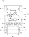
- the steering function-equipped hub unit 1 has a function of independently steering each of left and right rear wheel 9R, 9R that are supported by a torsion beam suspension device Rs and is applied to each of the rear wheel 9R, 9R of a vehicle 10 having a front-wheel steer function.
- the steering function-equipped hub unit 1 includes a turning shaft-equipped hub bearing 15, a unit support member 3, and a steering actuator 5. As shown in Fig. 7 , the steering function-equipped hub units 1 can independently steer the left and right rear wheels 9R, 9R by a minute angle (about ⁇ 5 degrees) in conjunction with steering of left and right front wheels 9F, 9F through, e.g., an operation of a steering wheel. It should be noted that the steering function-equipped hub units 1 may cause the left and right wheels to independently assume, not only the minute angle, a relatively large angle (for example, 10° to 20°) according to a vehicle control request.
- a relatively large angle for example, 10° to 20°
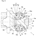
- the turning shaft-equipped hub bearing 15 is disposed on an outboard side of the unit support member 3.
- the term "outboard side” refers to an outer side of the vehicle 10 ( Fig. 7 ) in a vehicle widthwise direction in a state where the steering function-equipped hub unit 1 is mounted in the vehicle 10 ( Fig. 7 ), and the term “inboard side” refers to a side closer to a center of the vehicle 10 ( Fig. 7 ) in the vehicle widthwise direction.
- the turning shaft-equipped hub bearing 15 is supported by the unit support member 3 through rotation-permitting support components 4, 4 at two upper and lower positions such that turning shafts 16b, 16b extending in a vertical direction are rotatable about a turning axis A.
- the turning axis A is different from a rotation axis O of the rear wheel 9R ( Fig. 7 ).
- the turning shaft-equipped hub bearing 15 connects a member on a vehicle body side to the rear wheel 9R ( Fig. 7 ) and allows the rear wheel 9R ( Fig. 7 ) to smoothly rotate.
- the turning shaft-equipped hub bearing 15 includes an inner ring 18, an outer ring 19, rolling elements 20 such as balls interposed between the inner and outer rings 18, 19, and the turning shafts 16b, 16b extending in the vertical direction.
- the turning shaft-equipped hub bearing 15 further includes an arm part 17 as described later.
- the turning shaft-equipped hub bearing 15 is an angular ball bearing including the outer ring 19 as a stationary ring, the inner ring 18 as a rotary ring, and the rolling elements 20 arranged in double rows.
- the inner ring 18 includes a hub axle part 18a that includes a hub flange 18aa and constitutes a raceway surface on the outboard side and an inner ring part 18b that constitutes a raceway surface on an inboard side.
- the rear wheel 9R ( Fig. 7 ) has a wheel body fixed to the hub flange 18aa by a bolt in an overlapping manner with a brake rotor (not illustrated). The inner ring 18 rotates about the rotation axis O.
- the turning shafts 16b, 16b are trunnion shaft-type parts provided so as to upwardly and downwardly protrude from an outer periphery of the outer ring 19.
- Each of the turning shafts 16b is coaxial with the turning axis A.
- the respective turning shafts 16b are integrally formed on the outer ring 19 in the illustrated example, it is also possible, for instance, to provide fittable annular parts on an outer peripheral surface of the outer ring 19 and then provide the turning shafts so as to protrude upwardly and downwardly from outer peripheries of the annular parts.
- integrally formed means that the outer ring 19 and the turning shafts 16b are shaped as a part of a single object made of a single material through, e.g., forging or mechanical processing, instead of being constituted by multiple elements jointed together.
- a brake includes the brake rotor and a non-illustrated brake caliper.
- the brake caliper is attached to brake caliper attachment parts 22 at two upper and lower positions, each of the brake caliper attachment parts being formed integrally with the outer ring 19 so as to protrude in an arm-like manner.
- the torsion beam suspension device Rs has left and right opposite side parts each attached with a unit support member 3 for the steering function-equipped hub unit 1.
- the torsion beam suspension device Rs and the steering function-equipped hub units 1 attached to the suspension device Rs through the unit support members 3 constitute a suspension device-hub unit assembly AS.
- the suspension device Rs include a pair of left and right trailing arms Ta, Ta each extending in a front-rear direction of a vehicle body 10a ( Fig. 7 ), a torsion beam Tb connecting the trailing arms Ta, Ta, coil springs Cb (see Fig. 5 ) and shock absorbers.
- Each of the unit support members 3 is fixed to an attachment part 34 provided to one end portion (a rear end portion) of a corresponding trailing arm Ta.
- Each of the unit support members 3 is removably fixed to an outboard side surface of corresponding one of the left and right attachment parts 34 through a bolt or the like.
- Each trailing arm Ta has the other end portion provided with a rotation support part Taa.
- the left and right rotation support parts Taa, Taa are supported so as to be rotatable relative to the vehicle body 10a ( Fig. 7 ) about an axis in the vehicle widthwise direction in a mutually coaxial manner.
- the left and right trailing arms Ta, Ta are attached to the vehicle body 10a ( Fig.
- Spring sheets Ss, Ss to which lower end portions of the coil springs are attached are provided to a rear end portion of the torsion beam Tb at positions near opposite longitudinal ends of the torsion beam.
- each of the rotation-permitting support components 4 includes a rolling bearing.
- a tapered roller bearing is used as the rolling bearing.
- the rolling bearing includes: an inner ring 4a fitted to an outer periphery of the turning shaft 16b; an outer ring 4b fitted to the unit support member 3; and a plurality of rolling elements 4c interposed between the inner ring 4a and the outer ring 4b.
- the upper and lower rolling bearings are located inside the wheel body.
- the unit support member 3 has upper and lower parts 3A, 3B each formed with a fitting hole, and the outer ring 4b is fittedly fixed to the respective fitting holes.
- the respective fitting holes are coaxial with the turning axis A.
- Each of the turning shafts 16b is formed with a female thread part, and a bolt 23 is screwed into the female thread part.
- the bolt 23 screwed into the female thread part applies a pressing force to an end face of the inner ring 4a, with a pressing member 24 of a disk shape interposed between the bolt and the end face of the inner ring 4a, so as to apply an appropriate preload to each rolling bearing.
- the initial preload is set such that the preload is maintained even when the weight of the vehicle acts on the steering function-equipped hub unit 1.
- the steering function-equipped hub unit 1 can securely have the rigidity required for a steering device.
- rotation-permitting support components 4 are not limited to tapered roller bearings.
- the rotation-permitting support components 4 may be, for example, angular ball bearings depending on use conditions such as a maximal load ratio. Even in that case, a preload can be applied to the respective bearings in the same manner as above.
- the arm part 17 serves as a point of application at which an auxiliary steering force is applied to the outer ring 19 of the turning shaft-equipped hub bearing 15.
- the arm part 17 is integrally formed on a part of the outer periphery of the outer ring 19 so as to protrude radially outward.
- the arm part 17 is rotatably connected to an output rod 25a, which is a linear motion output part of the steering actuator 5, through a ball joint Bj.
- the output rod 25a of the steering actuator 5 advances and retreats, the turning shaft-equipped hub bearing 15 is caused to rotate, i.e., to be turned about the turning axis A.
- Use of the ball joint Bj eliminates the necessity of aligning attachment heights of the steering actuator 5 and the arm part 17 of the turning shaft-equipped hub bearing 15, so that a distance between the steering actuator 5 and the turning shaft-equipped hub bearing 15 can be arbitrarily set.
- the steering actuator 5 is separate from the unit support member 3 and is configured to rotationally drive the turning shaft-equipped hub bearing 15 about the turning axis A.
- the term "separate" means that the steering actuator 5 and the unit support member 3 are constituted by distinct elements that can be detached from each other.
- the steering actuator 5 includes a motor 26 that is a rotational drive source, a non-illustrated a speed reducer configured to reduce a speed of rotation of the motor 26, and a linear motion mechanism 25.
- the linear motion mechanism 25 is a mechanism configured to convert a forward/reverse rotation output from the speed reducer into a reciprocating linear motion of the output rod 25a.
- the motor 26 is, for example, a permanent magnet synchronous motor, or it may be a direct current motor or an induction motor.
- the speed reducer may be, for example, a winding-type transmission mechanism such as a belt transmission mechanism or a gear train.
- the linear motion mechanism 25 may be a feed screw mechanism of a slide screw type, such as a trapezoid screw or a triangle screw. In this example, a feed screw mechanism with a trapezoid sliding screw is used.
- the linear motion mechanism 25 includes the feed screw mechanism and a linear motion mechanism main body 25A.
- the linear motion mechanism main body 25A is a cover for covering constituting parts such as the feed screw mechanism.
- the feed screw mechanism includes a non-illustrated nut part and the output rod 25a that is a screw shaft.
- the output rod 25a is non-rotatable with respect to the linear motion mechanism main body 25A. It is also possible to use a mechanism for directly transmitting a driving force from the motor 26 to the linear motion mechanism 25 without involving a speed reducer.
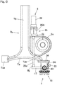
- the steering actuator 5 is attached to the suspension device Rs at a position higher than a lowermost surface Lv of the torsion beam Tb of the suspension device Rs and between the rotation support part Taa of the suspension device Rs and the turning shaft-equipped hub bearing 15.
- the linear motion mechanism main body 25A is fixed to a side surface of the torsion beam Tb of the suspension device Rs at a position near a longitudinal end of the torsion beam.
- the linear motion mechanism main body 25A extends in a left-right direction of the vehicle body and is fixed to the torsion beam Tb such that the output rod 25a can advance and retreat in the left-right direction.
- the linear motion mechanism main body 25A is disposed such that the output rod 25a faces the outboard side.
- the position of the arm part 17 of the turning shaft-equipped hub bearing 15 changes depending on the direction in which the steering actuator 5 is disposed. In order to efficiently steer the rear wheel with small energy, it is desirable to straightly move the arm part 17 back and forth in a direction perpendicular to the turning shaft 16b ( Fig. 3 ) of the turning shaft-equipped hub bearing 15.
- the arm part 17 and the steering actuator 5 are disposed such that the arm part 17 can be operated in that manner.
- the torsion beam Tb has, for example, a concave cross section when viewed in a plane perpendicular to a longitudinal direction of the torsion beam Tb, and the lowermost surface Lv of the torsion beam Tb is a leading-edge portion of an opening of the concave part.
- a torsion bar (not illustrated) may be incorporated in the torsion beam Tb.
- the turning shaft-equipped hub bearing 15 that support the rear wheel 9R can be arbitrarily rotated about the turning axis A by driving the steering actuator 5.
- an optimal steering angle can be achieved.
- the steering angle of the rear wheel 9R can be arbitrarily controlled according to travel conditions of the vehicle 10.
- the steering angle of the rear wheel 9R may be matched with a phase of a front wheel 9F so as to suppress a yaw generated in the vehicle 10 during steering and to enhance the stability of the vehicle 10.
- the steering angles on the left and right sides may be independently adjusted while traveling straight so as to ensure the stability of traveling of the vehicle 10.
- the steering actuator 5 is a separate component from the unit support member 3, the steering actuator 5 having an increased size can be disposed without causing interference with existing components. Thus, a stroke amount of the output rod 25a can be increased so as to achieve a desired steering angle.
- the steering actuator 5 which is separate from the unit support member 3 is attached to the suspension device Rs between the rotation support part Taa of the suspension device Rs and the turning shaft-equipped hub bearing 15, so that it is possible to suppress increase in the moment of inertia of the suspension device Rs and to prevent deterioration of the ride quality of the vehicle during bounding or the like in comparison with a conventional configuration in which the unit support member 3 and the steering actuator 5 are integrally provided.
- the heavy steering actuator 5 is mounted closer to the rotation support part Taa, the moment of inertia decreases, so that it is possible to prevent deterioration of the ride quality.
- the steering actuator 5 is a separate component from the unit support member 3, the mechanical elements have a greater choice of arrangements, making it possible to easily mount the steering function-equipped hub unit 1 in the vehicle 10 without losing a space for the existing components such as a shock absorber.
- the linear motion mechanism main body 25A is attached to the suspension device Rs such that the output rod 25a advances and retreats in the left-right direction of the vehicle body 10a, an empty space in the vehicle body 10a can be effectively used. Therefore, the steering function-equipped hub unit 1 can be easily mounted in vehicle 10 without involving a significant structural change to the vehicle 10.
- the turning shaft-equipped hub bearing 15 is supported by the unit support member 3 through the rotation-permitting support components 4, 4 at two upper and lower positions so as to be rotatable about the turning axis A, and the upper and lower rotation-permitting support components 4, 4 are located within a wheel body of a rear wheel 9R.
- the steering function-equipped hub unit 1 which can have a highly rigid and compact configuration, can be easily mounted in a vehicle. Therefore, as the steering function-equipped hub unit 1 can be easily mounted in an existing vehicle 10, the steering function-equipped hub unit 1 can have high versatility.
- the linear motion mechanism main body 25A of the steering actuator 5 extends in the front-rear direction of the vehicle and is fixed to one of the trailing arms Ta such that the output rod 25a advances and retracts in the front-rear direction.
- the steering actuator 5 is also attached to the suspension device Rs at a position higher than the lowermost surface Lv of the torsion beam Tb and between the rotation support part Taa and the turning shaft-equipped hub bearing 15.
- the arm part 17 of this example protrudes from the outer periphery of the outer ring 19 toward the inboard side.
- the unit support member 3 is formed with a cut part 3a for allowing the arm part 17 to protrude toward the inboard side, and the attachment part 34 is formed with a hole 34a for preventing interference with the arm part 17.
- This example also provides the same effects and advantages as those of the embodiment described above.
- the linear motion mechanism main body 25A may be fixed to the spring sheet Ss such that the linear motion mechanism main body 25A extends in the left-right direction of the vehicle body and the output rod 25a advances and retracts in the left-right direction.
- the linear motion mechanism main body 25A is disposed such that the output rod 25a extends toward the outboard side.
- the trailing arm Ta has a communication hole Tab that communicates a vehicle inner side with a vehicle outer side, and a part of the output rod 25a is located within the communication hole Tab. That is, the output rod 25a is disposed so as to pass through the communication hole Tab of the trailing arm Ta.
- the steering actuator 5 is disposed at a location where the steering actuator overlaps with the trailing arm Ta in a side view.
- the layout would be limited because the linear motion output part interferes with other components such as a spring.
- the linear motion output part is disposed so as to extend below the trailing arm, it is necessary to increase the lowest ground clearance of the vehicle in order to avoid interference between the linear motion output part and the ground.
- the output rod 25a that is a linear motion output part is disposed so as to pass through the communication hole Tab of the trailing arm Ta, it is possible to avoid interference with other components so that it is not necessary to increase the lowest ground clearance.
- the output rod 25a can have a reduced length in comparison with the case where the steering actuator is disposed at a location where the steering actuator does not overlap with the trailing arm in a side view.
- the steering actuator acts as a rigid member against torsion of the torsion beam so that the steering actuator would suppress the torsion and thereby may worsen the ride quality.
- the steering actuator 5 is fixed to the spring sheet Ss, so that the influence on the torsion of the torsion beam Tb is suppressed, and ride quality can be ensured.
- a single steering actuator 5 may be used to steer the left and right rear wheels 9R, 9R.
- the steering actuator 5 is fixed to the torsion beam Tb such that the linear motion mechanism main body 25A extends in the left-right direction of the vehicle body 10a.
- the single steering actuator 5 is provided with left and right output rods 25a, 25a each extending toward an outboard side. In this case, it is possible to reduce the weight and to suppress the moment of inertia in comparison with the configuration where two steering actuators are used to steer the left and right rear wheels. In this case, however, the steering angles of the left and right rear wheels 9R, 9R are controlled in phase. Otherwise, the same effects and advantages as those of the first embodiment are obtained.
- a steering system SY includes a steering function-equipped hub unit 1 according to any of the above embodiments and a control device 29 configured to control a steering actuator 5 ( Fig. 1 , Fig. 4 , Fig. 5 , Fig. 8 ) of the steering function-equipped hub unit 1.
- the control device 29 includes a steering control section 30 and an actuator drive control section 31.
- a driver operates turning angles of the front wheels 9F through the steering wheel.
- a higher-order control section 32 outputs a steering angle command signal to the left and right rear wheels 9R, 9R which is calculated according to an operation angle of a steering input part 11a (i.e., the steering wheel) in consideration of conditions of the vehicle 10.
- the steering control section 30 outputs a current command signal according to the steering angle command signal given from the higher-order control section 32.
- the higher-order control section 32 is a control section that is superordinate to the steering control section 30.
- the higher-order control section 32 may include, for example, an electronic control unit (or vehicle control unit, abbreviated as VCU) for performing general control of a vehicle.
- VCU vehicle control unit
- the actuator drive control section 31 outputs current according to a current command signal inputted from the steering control section 30 so as to drive and control the steering actuator 5.
- one steering actuator 5 is provided with one actuator drive control section 31.
- the actuator drive control section 31 controls electric power to be supplied to a coil of the motor 26 ( Fig. 1 , Fig. 4 , Fig. 5 , Fig. 8 ).
- the actuator drive control section 31 constitutes, for example, a non-illustrated half-bridge circuit including a switch element and performs PWM control for determining a motor application voltage with an ON-OFF duty cycle of the switch element. In this way, an angle of the turning shaft-equipped hub bearing 15 ( Fig. 1 , Fig.
- the steering angle of the rear wheel 9R can be changed according to traveling conditions of the vehicle 10 so that it is possible to improve motion performance and fuel economy of the vehicle 10.
- the steering system SY may operate the steering actuator 5 in response to a command from a non-illustrated automated drive device or a non-illustrated drive assistance device, instead of an operation of the steering wheel by a driver.
Landscapes
- Engineering & Computer Science (AREA)
- Mechanical Engineering (AREA)
- Chemical & Material Sciences (AREA)
- Combustion & Propulsion (AREA)
- Transportation (AREA)
- Vehicle Body Suspensions (AREA)
- Steering-Linkage Mechanisms And Four-Wheel Steering (AREA)
- Power Steering Mechanism (AREA)
Applications Claiming Priority (1)
| Application Number | Priority Date | Filing Date | Title |
|---|---|---|---|
| JP2019214179A JP2021084504A (ja) | 2019-11-27 | 2019-11-27 | 操舵機能付ハブユニット |
Publications (1)
| Publication Number | Publication Date |
|---|---|
| EP3828057A1 true EP3828057A1 (de) | 2021-06-02 |
Family
ID=73543189
Family Applications (1)
| Application Number | Title | Priority Date | Filing Date |
|---|---|---|---|
| EP20209034.6A Pending EP3828057A1 (de) | 2019-11-27 | 2020-11-20 | Mit lenkfunktion ausgestattete nabeneinheit |
Country Status (4)
| Country | Link |
|---|---|
| US (1) | US20210155283A1 (de) |
| EP (1) | EP3828057A1 (de) |
| JP (1) | JP2021084504A (de) |
| CN (1) | CN112849261A (de) |
Families Citing this family (1)
| Publication number | Priority date | Publication date | Assignee | Title |
|---|---|---|---|---|
| KR20210070448A (ko) * | 2019-12-04 | 2021-06-15 | 현대자동차주식회사 | 차량용 현가 장치 |
Citations (4)
| Publication number | Priority date | Publication date | Assignee | Title |
|---|---|---|---|---|
| JPH02299981A (ja) * | 1989-05-15 | 1990-12-12 | Mazda Motor Corp | 車両の後輪操舵装置 |
| DE102008002639A1 (de) * | 2008-06-25 | 2009-12-31 | Zf Friedrichshafen Ag | Verbundlenkerachse |
| JP2010052584A (ja) * | 2008-08-28 | 2010-03-11 | Honda Motor Co Ltd | リヤサスペンション装置 |
| JP2020050231A (ja) | 2018-09-28 | 2020-04-02 | Ntn株式会社 | 操舵機能付ハブユニットおよびこれを備えた車両 |
Family Cites Families (12)
| Publication number | Priority date | Publication date | Assignee | Title |
|---|---|---|---|---|
| JP2004122932A (ja) * | 2002-10-02 | 2004-04-22 | Nissan Motor Co Ltd | 車両用懸架装置 |
| FR2853281B1 (fr) * | 2003-04-04 | 2005-05-27 | Renault Sa | Essieu souple arriere a palonnier, et vehicule correspondant |
| FR2950290B1 (fr) * | 2009-09-24 | 2011-10-28 | Renault Sa | Essieu arriere directeur a support de palonnier et d'actionneur decouple |
| WO2011110788A1 (fr) * | 2010-03-11 | 2011-09-15 | Peugeot Citroën Automobiles SA | Dispositif de direction pour le train arrière d'un véhicule a moteur |
| JP5005067B2 (ja) * | 2010-05-28 | 2012-08-22 | 本田技研工業株式会社 | サスペンション装置 |
| JP5641335B2 (ja) * | 2011-01-31 | 2014-12-17 | 株式会社デンソー | 電力変換装置 |
| DE102011007283A1 (de) * | 2011-04-13 | 2012-10-18 | Bayerische Motoren Werke Aktiengesellschaft | Fahrzeug-Einzelradaufhängung für ein geringfügig lenkbares Hinterrad eines zweispurigen Fahrzeugs |
| DE102014104176A1 (de) * | 2013-03-28 | 2014-10-02 | Fuji Jukogyo Kabushiki Kaisha | Aufhängungsvorrichtung |
| JP6982417B2 (ja) * | 2017-06-23 | 2021-12-17 | Ntn株式会社 | 補助転舵機能付ハブユニットおよび車両 |
| JP6539326B2 (ja) * | 2017-10-13 | 2019-07-03 | 本田技研工業株式会社 | サスペンション装置 |
| KR20220036579A (ko) * | 2020-09-16 | 2022-03-23 | 현대자동차주식회사 | 서스펜션 결합구조 |
| US20220204078A1 (en) * | 2020-12-31 | 2022-06-30 | Ree Automotive Ltd. | Steering and suspension mechanism |
-
2019
- 2019-11-27 JP JP2019214179A patent/JP2021084504A/ja active Pending
-
2020
- 2020-11-20 EP EP20209034.6A patent/EP3828057A1/de active Pending
- 2020-11-24 US US17/103,030 patent/US20210155283A1/en not_active Abandoned
- 2020-11-26 CN CN202011345035.0A patent/CN112849261A/zh active Pending
Patent Citations (5)
| Publication number | Priority date | Publication date | Assignee | Title |
|---|---|---|---|---|
| JPH02299981A (ja) * | 1989-05-15 | 1990-12-12 | Mazda Motor Corp | 車両の後輪操舵装置 |
| DE102008002639A1 (de) * | 2008-06-25 | 2009-12-31 | Zf Friedrichshafen Ag | Verbundlenkerachse |
| JP2010052584A (ja) * | 2008-08-28 | 2010-03-11 | Honda Motor Co Ltd | リヤサスペンション装置 |
| JP4966273B2 (ja) | 2008-08-28 | 2012-07-04 | 本田技研工業株式会社 | リヤサスペンション装置 |
| JP2020050231A (ja) | 2018-09-28 | 2020-04-02 | Ntn株式会社 | 操舵機能付ハブユニットおよびこれを備えた車両 |
Also Published As
| Publication number | Publication date |
|---|---|
| CN112849261A (zh) | 2021-05-28 |
| JP2021084504A (ja) | 2021-06-03 |
| US20210155283A1 (en) | 2021-05-27 |
Similar Documents
| Publication | Publication Date | Title |
|---|---|---|
| US11731693B2 (en) | Hub unit with steering function, steering system, and vehicle | |
| US11565548B2 (en) | Hub unit having steering function, and vehicle provided with said hub unit | |
| CN111094114B (zh) | 带有辅助转向功能的轮毂单元和具有它的车辆 | |
| WO2018235892A1 (ja) | 補助転舵機能付ハブユニットおよび車両 | |
| US20210197887A1 (en) | Hub unit having steering function and vehicle provided with hub unit | |
| EP3828057A1 (de) | Mit lenkfunktion ausgestattete nabeneinheit | |
| JP6899465B2 (ja) | 転舵軸付ハブベアリングおよびこれを備えた車両 | |
| WO2018235891A1 (ja) | 補助転舵機能付ハブユニットおよび車両 | |
| US11851123B2 (en) | Hub unit having steering function, and vehicle equipped with same | |
| JP2020097280A (ja) | 操舵機能付ハブユニットおよび操舵システム | |
| JP7060984B2 (ja) | 転舵機能付ハブユニットおよびこれを備えた車両 | |
| WO2019189102A1 (ja) | 操舵機能付ハブユニットおよびこれを備えた車両 | |
| JP2020097268A (ja) | 操舵機能付ハブユニットおよびこれを備えた車両 | |
| JP2020097964A (ja) | 直動機構、操舵機能付ハブユニットおよびこれを備えた車両 | |
| JP6899464B2 (ja) | 転舵軸付ハブベアリングおよびこれを備えた車両 | |
| JP6720393B2 (ja) | 転舵軸付ハブベアリングおよび転舵機能付ハブユニット | |
| WO2021106894A1 (ja) | 操舵機能付ハブユニットおよびこれを備えた車両 | |
| JP7296332B2 (ja) | 操舵機能付ハブユニットおよびこれを備えた車両 | |
| WO2024048562A1 (ja) | 操舵機能付ハブユニット、操舵システムおよび車両 | |
| JP2021098395A (ja) | 操舵機能付ハブユニットおよびこれを備えた車両 | |
| JP2023047456A (ja) | 操舵機能付ハブユニット、操舵システムおよび車両 | |
| JP2022114979A (ja) | 操舵機能付ハブユニット、操舵システムおよび車両 |
Legal Events
| Date | Code | Title | Description |
|---|---|---|---|
| PUAI | Public reference made under article 153(3) epc to a published international application that has entered the european phase |
Free format text: ORIGINAL CODE: 0009012 |
|
| STAA | Information on the status of an ep patent application or granted ep patent |
Free format text: STATUS: THE APPLICATION HAS BEEN PUBLISHED |
|
| AK | Designated contracting states |
Kind code of ref document: A1 Designated state(s): AL AT BE BG CH CY CZ DE DK EE ES FI FR GB GR HR HU IE IS IT LI LT LU LV MC MK MT NL NO PL PT RO RS SE SI SK SM TR |
|
| STAA | Information on the status of an ep patent application or granted ep patent |
Free format text: STATUS: REQUEST FOR EXAMINATION WAS MADE |
|
| 17P | Request for examination filed |
Effective date: 20211202 |
|
| RBV | Designated contracting states (corrected) |
Designated state(s): AL AT BE BG CH CY CZ DE DK EE ES FI FR GB GR HR HU IE IS IT LI LT LU LV MC MK MT NL NO PL PT RO RS SE SI SK SM TR |
|
| STAA | Information on the status of an ep patent application or granted ep patent |
Free format text: STATUS: EXAMINATION IS IN PROGRESS |
|
| 17Q | First examination report despatched |
Effective date: 20230905 |