EP3827695A1 - Vorrichtung zum aufwickeln von haarsträhnen - Google Patents
Vorrichtung zum aufwickeln von haarsträhnen Download PDFInfo
- Publication number
- EP3827695A1 EP3827695A1 EP20207353.2A EP20207353A EP3827695A1 EP 3827695 A1 EP3827695 A1 EP 3827695A1 EP 20207353 A EP20207353 A EP 20207353A EP 3827695 A1 EP3827695 A1 EP 3827695A1
- Authority
- EP
- European Patent Office
- Prior art keywords
- winding body
- hair
- notch
- notches
- strand
- Prior art date
- Legal status (The legal status is an assumption and is not a legal conclusion. Google has not performed a legal analysis and makes no representation as to the accuracy of the status listed.)
- Granted
Links
Images
Classifications
-
- A—HUMAN NECESSITIES
- A45—HAND OR TRAVELLING ARTICLES
- A45D—HAIRDRESSING OR SHAVING EQUIPMENT; EQUIPMENT FOR COSMETICS OR COSMETIC TREATMENTS, e.g. FOR MANICURING OR PEDICURING
- A45D2/00—Hair-curling or hair-waving appliances ; Appliances for hair dressing treatment not otherwise provided for
- A45D2/02—Hair winders or hair curlers for use substantially perpendicular to the scalp, i.e. steep-curlers
Definitions
- volume curlers which are designed as hollow cylinders and have a diameter of about 3 to 7 cm, are used for physical reshaping of the hair. Individual wet strands of hair are wound up parallel to the volume curlers in accordance with the desired direction of fall of the hair and fixed there by inserting pins through openings in the surface of the volume curlers. It is particularly important to ensure that the pins do not injure the scalp. After the hair has been dried, for example with the aid of a drying hood, the volume curlers are removed from the hair. Volume curlers are primarily used to give the hair more volume and a loose, moving fall. However, the durability of such a deformation is low. In particular, the effect is lost immediately as soon as the hair becomes damp.
- the object of the present invention is to provide a device for winding up strands of hair which is easy to use and at the same time is gentle on the hair and the scalp.
- the invention relates to a device for winding up strands of hair, comprising a solid, cylindrical winding body with a first end and a second end and a lateral surface, with at least two spaced apart in the winding body in the direction of the longitudinal extension of the winding body Notches are formed, each notch extending from the jacket surface at a mean angle ⁇ with respect to a radial direction into the interior of the winding body.
- the angle ⁇ is understood to mean a mean angle through which a mean direction and extent of a notch can be described.
- several notches in a winding body can extend into the interior of the winding body at the same angles ⁇ or at different angles ⁇ with respect to a radial direction.
- the device according to the invention for winding up strands of hair has a cylindrical winding body which, starting from its outer jacket surface, comprises at least two notches which extend into the interior of the winding body. Due to the special design of the winding body, no further components, in particular no locking means, are required for its use.
- a strand of hair to be wound up is passed through a first notch in the winding body close to the head. This fixes the bobbin on the head.
- the strand of hair is then guided around the cylindrical winding body, for example in a spiral shape, until it is almost completely wound onto it.
- the lower, head-remote end of the hair strand is passed through a second notch in the winding body.
- the strand of hair is locked in this way on the winding body without the need for a separate locking means such as a rubber band, a needle or a clamp. Rather, the hair is locked on the bobbin by the interaction of the at least two notches in the bobbin, which are spaced apart from one another in the direction of the longitudinal extension of the bobbin and which, starting from the lateral surface, extend at a mean angle ⁇ with respect to a radial direction in extend into the interior of the bobbin.
- a strand of hair is passed both with its end near the head and with its end remote from the head through a notch and in this way is locked on the winding body without any further aids.
- the application of the device according to the invention particularly simple and time-saving, in particular it is also suitable for domestic use and can be used by a user without the help of a hairdresser.
- the device according to the invention is gentle on both the hair and the scalp, since there can be neither constrictions and / or pressure points, nor can the scalp be injured by separate locking means.
- the device according to the invention can be used for both physical and chemical transformations and can be reused many times over, which is advantageous against the background of sustainability.
- the notches extend, starting from the lateral surface of the winding body, at an average angle ⁇ different from 0 ° with respect to a radial direction obliquely into the interior of the winding body.
- a radial component is understood to mean a component in the direction of the radius of the cylindrical wound body
- an axial component is understood to mean a component in the direction of the longitudinal axis of the wound body.
- the ratio of the axial component to the radial component can change in sections over the length of the notch.
- one or more notches can also extend into the interior of the winding body at an average angle ⁇ of 0 ° with respect to a radial direction.
- an obliquely aligned notch can extend obliquely upwards towards the upper end of the winding body or obliquely downwards towards the lower end with respect to a radial direction starting from the jacket surface to extend the bobbin.
- a first notch which is arranged adjacent to the upper end of the winding body, can extend obliquely upward
- a second notch which is arranged adjacent to the lower end of the winding body, can extend obliquely downward.
- the first notch which extends obliquely upward, gives the winding body a hook-like shape in the upper area. It can accordingly be hooked close to the head in a strand of hair held away from the head and holds there without the need for further fixation.
- the notches taper starting from the jacket surface into the interior of the winding body.
- a strand of hair can be introduced without difficulty into the comparatively wide opening of a notch in the area of the lateral surface, while it then passes through the tapered, for example tapering, apex area of the Notch is anchored and held in place.
- at least one notch has a sickle-shaped cross section.
- the at least two notches are arranged offset from one another in the circumferential direction of the winding body.
- two notches can be arranged in areas diametrically opposite one another in the circumferential direction of the winding body.
- the mean angle ⁇ between two notches in the circumferential direction of the winding body can be between 0 ° and 360 °.
- the notches lie on the same side of the winding body; at an average angle of 180 °, they lie on diametrically opposite sides.
- all notches can be formed on the same side of the winding body; all notches can also be arranged offset from one another by a certain angle.
- two notches on the same side and one or more further notches can be arranged offset thereto by an angle ⁇ .
- One embodiment of the invention provides that a first notch is arranged adjacent to the first end of the winding body and a second notch is arranged adjacent to the second end of the winding body.
- a strand of hair can be inserted into the first notch at the first end of the winding former, then wound up over the entire length of the winding former, for example in a spiral wrap, and finally through the second notch for locking at the second end of the winding former be passed through.
- the first notch can advantageously extend obliquely from the jacket surface to the first end of the winding body, whereby the advantageous hook-like shape of the winding body already described above is achieved, while the second notch extends obliquely starting from the jacket surface on the second end of the bobbin to extend.
- the third notch can be arranged centrally between the first and the second notch in the direction of the longitudinal extension of the winding body.
- the first notch can be arranged adjacent to the first end of the wound body, the second notch adjacent to the second end of the wound body, and the third notch at approximately half the length of the wound body. In this way, a strand of hair can also be passed through a further notch approximately halfway along its length, which makes it even easier to fix the strand of hair, especially in the case of long hair.
- a third notch can, for example, also be arranged closer to the second notch than to the first notch.
- the second and third notches offer alternative anchoring options for the end of a strand of hair away from the head, depending on the length of the hair. With very long hair, a strand of hair can be guided over the entire length of the winding body and locked in the lowest, second notch. With shorter hair, a strand of hair can be locked in the third notch between the first and second notches. the second notch remains unused in this case.
- the strand of hair can be guided through all of the notches and / or the end of the strand of hair remote from the head can be locked in a notch corresponding to the length of the strand of hair.
- uniform winding bodies can be used in this way for hair of different lengths, with a strand of hair always being reliably locked due to the provision of several notches at different heights of the winding body.
- the length of the wound body extending between the first and second ends can be approximately between 10 cm and 20 cm, preferably between 13 cm and 18 cm.
- the diameter of the wound body can be in the range from about 1 cm to 4 cm, preferably between 1.5 cm and 2.5 cm.
- the winding body is made of an elastic material.
- the regions of the winding body which delimit the notch towards the outside spring slightly outwards when a strand of hair is passed through the notch due to the elasticity of the material.
- restoring forces become effective within the winding body, which try to force the outwardly sprung areas back into their starting position.
- the strand of hair is to a certain extent clamped in the notch, in particular in the apex area of the notch.
- the clamping effect is not so strong that pressure points would remain on the hair.
- it is sufficiently large to prevent the strand of hair from slipping out of the notch and to ensure that the winding body is securely anchored on the head.
- the winding body can be made from a foam.
- a foam offers good elasticity with a low weight at the same time. The latter is particularly advantageous when many, for example 15 or more, winding bodies are anchored in the hair at the same time.
- a winding body according to the invention made of a foam material weighs only about one to two grams, depending on length and diameter.
- a foam material usually has a certain surface roughness, which, in addition to the described clamping effect, prevents the strand of hair from slipping out of a notch via additional friction effects.
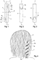
- FIG. 1 shows an embodiment of the device according to the invention in a side sectional view.
- the device comprises a solid, cylindrical winding body 1, which is made from a foam.
- L denotes the direction of the longitudinal extension of the wound body.
- the winding body 1 comprises a first end 2 and a second end 3 as well as a jacket surface 4 delimiting the winding body towards the outside.
- the winding body 1 In the direction of its longitudinal extent L, the winding body 1 has a length of approximately 15 cm.
- the diameter of the cylindrical winding body 1 is about 2 cm, its weight about 1.2 g.
- two notches 5a, 5b are formed which are spaced apart from one another in the direction of the longitudinal extension L of the winding body 1, the notch 5a being arranged adjacent to the first end 2 and the notch 5b being arranged adjacent to the second end 3 of the winding body 1.
- the two notches 5a, 5b extend, starting from the jacket surface 4, into the interior of the winding body 1, whereby, starting from the jacket surface 4, they taper into the interior of the winding body 1.
- the notch 5a thus tapers starting from an opening 6a in the jacket surface 4 to an apex region 7a
- the notch 5b tapers starting from an opening 6b in the jacket surface 4 to an apex region 7b.
- the notches 5a and 5b each have a sickle-shaped cross section.
- the notch 5a extends obliquely upwards towards the first end 2, while the notch 5b extends obliquely downwards towards the second end 3 into the interior of the winding body 1.
- a mean angle ⁇ is shown, at which the notch 5a extends into the interior of the winding body 1 with respect to a radial direction R.
- the two notches 5a, 5b are arranged offset from one another by an average angle of 180 °. They are therefore on diametrically opposite sides of the winding body 1.
- FIGS. 2 and 3 show the bobbin 1 from Figure 1 each in a perspective view, wherein Figure 2 a view from the front and Figure 3 shows a view rotated by 180 ° from the rear. Due to the diametrically opposed notches 5a, 5b in Figure 2 only the upper notch 5a can be seen, while in Figure 3 only the lower notch 5b can be seen. Outwardly, the notch 5a is bounded by a free leg 8a, while the notch 5b is bounded by a free leg 8b.
- the strand of hair 10 is then repeatedly wound in a spiral shape around the winding body 1 until finally the end of the strand of hair 10 remote from the head is passed through the lower notch 5b and held there by clamping, whereby the strand of hair 10 is fixed on the winding body 1.
- the winding body 1 is thus firmly anchored in the hair and the strand of hair 10 is held securely and in the desired shape on it.
- the winding body 1 can be attached clockwise or counterclockwise, ie the strand of hair 10 can be wound onto the winding body 1 in a clockwise or counterclockwise direction.
- no separate locking means are required, in particular no rubber band, no clamp and no fixed pin.
- the lock of the strand of hair 10 on the winding body 1 is brought about solely by the interaction of the two notches 5a, 5b in the winding body 1.
- the device according to the invention is thus significantly easier to handle than with conventional devices and it is equally suitable for use by a hairdresser as for domestic use.
Landscapes
- Hair Curling (AREA)
Abstract
Description
- Derartige Vorrichtungen, die auch als Lockenwickler bezeichnet werden, sind in unterschiedlichen Ausführungen bekannt. So werden für physikalische Umformungen des Haares sogenannte Volumenwickler eingesetzt, die als Hohlzylinder ausgebildet sind und einen Durchmesser von etwa 3 bis 7 cm aufweisen. Einzelne nasse Haarsträhnen werden entsprechend der gewünschten Fallrichtung des Haares parallel auf die Volumenwickler aufgewickelt und dort fixiert, indem Feststecknadeln durch Durchbrechungen in der Mantelfläche der Volumenwickler hindurchgesteckt werden. Hierbei ist besonders darauf zu achten, dass es durch die Feststecknadeln nicht zu Verletzungen der Kopfhaut kommt. Nach Trocknung des Haars, beispielsweise unter Zuhilfenahme einer Trockenhaube, werden die Volumenwickler aus dem Haar entfernt. Volumenwickler werden vorrangig dafür eingesetzt, dem Haar mehr Volumen und einen lockeren, bewegten Fall zu verleihen. Die Haltbarkeit einer solchen Umformung ist jedoch gering. Insbesondere geht die Wirkung unmittelbar verloren, sobald das Haar feucht wird.
- Bei sogenannten chemischen Umformungen steht eine dauerhaftere Umformung des Haares im Vordergrund. Hierfür werden in der Regel kleinere Wickler eingesetzt als bei der physikalischen Umformung. Zusätzlich wird das Haar nach dem Aufwickeln der einzelnen Haarsträhnen auf die Wickler mit einer chemischen Substanz, einem sogenannten Wellmittel, benetzt. Während der Einwirkzeit verändert sich die natürliche Struktur des Haars. Es wird verformbar und nimmt die durch den Wickler, insbesondere durch den Wicklerdurchmesser, vorgegebene Form an. Nach dem Ausspülen des Wellmittels wird in einem abschließenden Schritt ein Fixiermittel appliziert, um die vorgenommene Formänderung zu fixieren. Das Aufwickeln der Haarsträhnen auf die kleinen Wickler erfordert eine hohe Präzision und viel Erfahrung. So ist darauf zu achten, dass das Haar zunächst sehr präzise gescheitelt wird und dass beim Aufwickeln eine gleichmäßige Spannung auf das Haar ausgeübt wird. Die Arretierung der Haarsträhnen auf den Wicklern erfolgt mit Hilfe von Gummibändern und/oder Klammern, wodurch jedoch mitunter unerwünschte Druckstellen am Haar verursacht werden.
- Für die Anwendung der bekannten Wickler sind sowohl bei der physikalischen als auch bei der chemischen Umformung neben dem Wickler selbst stets separate Arretiermittel wie Feststecknadeln, Gummibänder oder Klammern erforderlich. Dies bedeutet für den Friseur, dass er zur Befestigung mit der einen Hand die unter Spannung auf den Wickler aufgewickelte Haarsträhne halten muss, während er mit der anderen Hand das Arretiermittel anbringt. Eine solche Handhabung ist umständlich und zeitaufwändig und daher verbesserungswürdig.
- Die Aufgabe der vorliegenden Erfindung ist es, eine Vorrichtung zum Aufwickeln von Haarsträhnen bereitzustellen, welche einfach in der Anwendung ist und gleichzeitig das Haar und die Kopfhaut schont.
- Diese Aufgabe wird gelöst durch eine Vorrichtung mit den Merkmalen des Patentanspruchs 1.
- Vorteilhafte Ausgestaltungen und Weiterbildungen der Erfindung sind Gegenstand der abhängigen Ansprüche.
- Gemäß Patentanspruch 1 handelt es sich bei der Erfindung um eine Vorrichtung zum Aufwickeln von Haarsträhnen, umfassend einen massiven, zylinderförmigen Wickelkörper mit einem ersten Ende und einem zweiten Ende und einer Mantelfläche, wobei in dem Wickelkörper mindestens zwei in Richtung der Längserstreckung des Wickelkörpers beabstandet voneinander angeordnete Kerben ausgebildet sind, wobei sich jede Kerbe ausgehend von der Mantelfläche unter einem mittleren Winkel α bezüglich einer radialen Richtung in das Innere des Wickelkörpers hinein erstreckt.
- Unter dem Winkel α wird dabei ein mittlerer Winkel verstanden, durch welchen eine mittlere Richtung und Erstreckung einer Kerbe beschrieben werden kann. Grundsätzlich können sich dabei mehrere Kerben in einem Wickelkörper unter gleichen Winkeln α oder unter verschiedenen Winkeln α bezüglich einer radiale Richtung in das Innere des Wickelkörpers hinein erstrecken.
- Mit anderen Worten weist die erfindungsgemäße Vorrichtung zum Aufwickeln von Haarsträhnen einen zylinderförmigen Wickelkörper auf, welcher ausgehend von seiner äußeren Mantelfläche mindestens zwei Kerben umfasst, die sich in das Innere des Wickelkörpers hinein erstrecken. Aufgrund der speziellen Ausgestaltung des Wickelkörpers sind für seine Anwendung keine weiteren Komponenten, insbesondere keine Arretiermittel, erforderlich. Eine aufzuwickelnde Haarsträhne wird kopfnah durch eine erste Kerbe des Wickelkörpers hindurchgeführt. Hierdurch wird der Wickelkörper am Kopf fixiert. Sodann wird die Haarsträhne, beispielsweise spiralförmig, solange um den zylindrischen Wickelkörper herumgeführt, bis sie nahezu vollständig auf diesen aufgewickelt ist. Zur Arretierung der Haarsträhne auf dem Wickelkörper wird das untere, kopfferne Ende der Haarsträhne durch eine zweite Kerbe des Wickelkörpers hindurchgeführt. Die Haarsträhne wird auf diese Weise auf dem Wickelkörper arretiert, ohne dass ein separates Arretiermittel wie ein Gummiband, eine Nadel oder eine Klammer erforderlich wäre. Vielmehr wird die Arretierung des Haars an dem Wickelkörper durch das Zusammenwirken der mindestens zwei Kerben in dem Wickelkörper bewirkt, welche in Richtung der Längserstreckung des Wickelkörpers beabstandet voneinander angeordnet sind und welche sich ausgehend von der Mantelfläche jeweils unter einem mittleren Winkel α bezüglich einer radialen Richtung in das Innere des Wickelkörpers hinein erstrecken. Eine Haarsträhne wird sowohl mit ihrem kopfnahen Ende als auch mit ihrem kopffernen Ende durch jeweils eine Kerbe hindurchgeführt und auf diese Weise ohne weitere Hilfsmittel an dem Wickelköper arretiert. Aus diesem Grund ist die Anwendung der erfindungsgemäßen Vorrichtung besonders einfach und zeitsparend, insbesondere ist sie auch für den Hausgebrauch geeignet und kann von einem Nutzer auch ohne die Hilfe eines Friseurs angewendet werden. Darüber hinaus schont die erfindungsgemäße Vorrichtung sowohl das Haar als auch die Kopfhaut, da es weder zu Einschnürungen und/oder Druckstellen, noch zu Verletzungen der Kopfhaut durch separate Arretiermittel kommen kann.
- Die erfindungsgemäße Vorrichtung kann sowohl für physikalische als auch für chemische Umformungen eingesetzt werden und kann vielfach wiederverwendet werden, was vor dem Hintergrund der Nachhaltigkeit vorteilhaft ist.
- Gemäß einer vorteilhaften Ausgestaltung der Erfindung erstrecken sich die Kerben ausgehend von der Mantelfläche des Wickelkörpers unter einem von 0° verschiedenen mittleren Winkel α bezüglich einer radialen Richtung schräg in das Innere des Wickelkörpers hinein. Durch eine solche schräge Erstreckung einer Kerbe kann ein versehentliches Herausrutschen der Haarsträhne aus der Kerbe im Wesentlichen verhindert werden. Bei sich schräg erstreckenden Kerben weisen die Richtungen, in die sich die Kerben ausgehend von der Mantelfläche in den Wickelkörper hinein erstrecken, sowohl eine radiale als auch eine axiale Komponente auf. Unter einer radialen Komponente wird dabei eine Komponente in Richtung des Radius des zylinderförmigen Wickelkörpers verstanden, unter einer axialen Komponente wird eine Komponente in Richtung der Längsachse des Wickelkörpers verstanden. Je nach Verlauf und Formgebung einer gegebenen Kerbe kann sich das Verhältnis von axialer Komponente zu radialer Komponente über die Länge der Kerbe abschnittsweise ändern. Grundsätzlich können sich eine oder mehrere Kerben jedoch auch unter einem mittleren Winkel α von 0° bezüglich einer radialen Richtung in das Innere des Wickelkörpers hinein erstrecken.
- Bei einer Ausrichtung des Wickelkörpers, bei welcher die Längsachse des Wickelkörpers mit einer vertikalen Richtung zusammenfällt, kann eine schräg ausgerichtete Kerbe sich bezüglich einer radialen Richtung ausgehend von der Mantelfläche schräg nach oben auf das obere Ende des Wickelkörpers zu oder schräg nach unten auf das untere Ende des Wickelkörpers zu erstrecken. Insbesondere kann sich eine erste Kerbe, welche angrenzend an das obere Ende des Wickelkörpers angeordnet ist, schräg nach oben erstrecken, während sich eine zweite Kerbe, welche angrenzend an das untere Ende des Wickelkörpers angeordnet ist, schräg nach unten erstrecken kann. Durch die sich schräg nach oben erstreckende erste Kerbe erhält der Wickelkörper im oberen Bereich eine hakenartige Gestalt. Er kann entsprechend kopfnah in eine vom Kopf weggehaltene Haarsträhne eingehakt werden und hält dort, ohne, dass eine weitere Fixierung notwendig wäre.
- Gemäß einem Vorschlag der Erfindung verjüngen sich die Kerben ausgehend von der Mantelfläche in das Innere des Wickelkörpers hinein. Auf diese Weise ist eine Haarsträhne ohne Schwierigkeiten in die vergleichsweise weite Öffnung einer Kerbe im Bereich der Mantelfläche einführbar, während sie sodann durch den verjüngt ausgebildeten, beispielsweise spitz zulaufenden Scheitelbereich der Kerbe verankert und festgehalten wird. Es kann dabei beispielsweise vorgesehen sein, dass mindestens eine Kerbe einen sichelförmigen Querschnitt aufweist.
- Eine Ausgestaltung der Erfindung sieht vor, dass die mindestens zwei Kerben in Umfangsrichtung des Wickelkörpers versetzt zueinander angeordnet sind. Beispielsweise können zwei Kerben in in Umfangsrichtung des Wickelkörpers einander diametral gegenüberliegenden Bereichen angeordnet sein. Im Allgemeinen kann der mittlere Winkel β zwischen zwei Kerben in Umfangsrichtung des Wickelkörpers zwischen 0° und 360° betragen. Bei einem Winkel β von 0° bzw. 360° liegen die Kerben auf der gleichen Seite des Wickelkörpers, bei einem mittleren Winkel von 180° liegen sie auf einander diametral gegenüberliegenden Seiten. Bei mehr als zwei Kerben können alle Kerben auf der gleichen Seite des Wickelkörpers ausgebildet sein, es können auch alle Kerben um einen gewissen Winkel gegeneinander versetzt angeordnet sein. Insbesondere können zwei Kerben auf der gleichen Seite und eine oder mehrere weitere Kerben um einen Winkel β dazu versetzt angeordnet sein.
- Ein Ausführungsbeispiel der Erfindung sieht vor, dass eine erste Kerbe angrenzend an das erste Ende des Wickelkörpers und eine zweite Kerbe angrenzend an das zweite Ende des Wickelkörpers angeordnet ist. In diesem Fall kann eine Haarsträhne an dem ersten Ende des Wickelkörpers in die erste Kerbe eingeführt werden, sodann über die gesamte Länge des Wickelkörpers auf diesen aufgewickelt werden, beispielsweise in einer Spiralwicklung, und abschließend zur Arretierung an dem zweiten Ende des Wickelkörpers durch die zweite Kerbe hindurchgeführt werden. Die erste Kerbe kann sich dabei in vorteilhafter Weise ausgehend von der Mantelfläche schräg auf das erste Ende des Wickelkörpers zu erstrecken, wodurch die oben bereits beschriebene vorteilhafte hakenartige Gestalt des Wickelkörpers erreicht wird, während die zweite Kerbe sich ausgehend von der Mantelfläche schräg auf das zweite Ende des Wickelkörpers zu erstrecken kann.
- Es können auch drei oder mehr Kerben vorgesehen sein, die in Richtung der Längserstreckung des Wickelkörpers beabstandet voneinander ausgebildet sind. Bei drei Kerben kann die dritte Kerbe in Richtung der Längserstreckung des Wickelkörpers mittig zwischen der ersten und der zweiten Kerbe angeordnet sein. Beispielsweise kann die erste Kerbe angrenzend an das erste Ende des Wickelkörpers, die zweite Kerbe angrenzend an das zweite Ende des Wickelkörpers und die dritte Kerbe etwa auf Höhe der halben Länge des Wickelkörpers angeordnet sein. Auf diese Weise kann eine Haarsträhne zusätzlich etwa auf halber Länge durch eine weitere Kerbe hindurchgeführt werden, wodurch eine Fixierung der Haarsträhne, insbesondere bei langem Haar, noch besser gelingt. Eine dritte Kerbe kann jedoch beispielsweise auch näher an der zweiten Kerbe als an der ersten Kerbe angeordnet sein. In diesem Fall bieten die zweite und die dritte Kerbe je nach Haarlänge alternative Verankerungsmöglichkeiten für das kopfferne Ende einer Haarsträhne. So kann bei sehr langem Haar eine Haarsträhne über die gesamte Länge des Wickelkörpers geführt und in der untersten, zweiten Kerbe arretiert werden. Bei kürzerem Haar kann eine Haarsträhne bereits in der zwischen der ersten und zweiten Kerbe angeordneten dritten Kerbe arretiert werden, die zweite Kerbe bleibt in diesem Fall ungenutzt. Bei mehr als drei Kerben kann analog ein Hindurchführen der Haarsträhne durch sämtliche Kerben und/oder ein Arretieren des kopffernen Endes der Haarsträhne in einer der Länge der Haarsträhne entsprechenden Kerbe erfolgen. Grundsätzlich können auf diese Weise für unterschiedlich langes Haar einheitliche Wickelkörper verwendet werden, wobei aufgrund des Vorsehens mehrerer Kerben auf unterschiedlichen Höhen des Wickelkörpers stets eine zuverlässige Arretierung einer Haarsträhne möglich ist.
- Die sich zwischen dem ersten und zweiten Ende erstreckende Länge des Wickelkörpers kann etwa zwischen 10 cm und 20 cm betragen, vorzugsweise zwischen 13 cm und 18 cm. Der Durchmesser des Wickelkörpers kann im Bereich von etwa 1 cm bis 4 cm liegen, vorzugsweise zwischen 1,5 cm und 2,5 cm.
- Bei einer besonders vorteilhaften Ausgestaltung der Erfindung ist der Wickelkörper aus einem elastischen Material gefertigt. In diesem Fall federn die die Kerbe nach außen hin begrenzenden Bereiche des Wickelkörpers beim Hindurchführen einer Haarsträhne durch die Kerbe aufgrund der Elastizität des Materials leicht nach außen. Hierdurch werden Rückstellkräfte innerhalb des Wickelkörpers wirksam, welche die nach außen gefederten Bereiche wieder in ihre Ausgangslage zurückzudrängen versuchen. Die Haarsträhne wird auf diese Weise gewissermaßen in der Kerbe, insbesondere im Scheitelbereich der Kerbe, eingeklemmt. Die Klemmwirkung ist dabei nicht so stark, dass Druckstellen auf dem Haar zurückbleiben würden. Gleichwohl ist sie aber ausreichend groß, um ein Herausrutschen der Haarsträhne aus der Kerbe zu verhindern und eine sichere Verankerung des Wickelkörpers am Kopf zu bewirken.
- Insbesondere kann der Wickelkörper aus einem Schaumstoff gefertigt sein. Ein Schaumstoff bietet eine gute Elastizität bei gleichzeitig geringem Eigengewicht. Letzteres ist insbesondere dann von Vorteil, wenn viele, beispielsweise 15 oder mehr, Wickelkörper gleichzeitig im Haar verankert werden. Ein erfindungsgemäßer Wickelkörper aus einem Schaumstoffmaterial wiegt je nach Länge und Durchmesser nur etwa ein bis zwei Gramm. Darüber hinaus weist ein Schaumstoffmaterial in der Regel eine gewisse Oberflächenrauhigkeit auf, welche neben der beschriebenen Klemmwirkung über zusätzliche Reibungseffekte ein Herausrutschen der Haarsträhne aus einer Kerbe verhindert.
- Im Folgenden wird die Erfindung anhand eines Ausführungsbeispiels und unter Bezugnahme auf die beigefügten Figuren näher erläutert.
- Es zeigen:
- Figur 1:
- Darstellung eines Ausführungsbeispiels der erfindungsgemäßen Vorrichtung von der Seite im Längsschnitt;
- Figur 2:
- die Vorrichtung aus
Figur 1 in einer perspektivischen Ansicht von vorne; - Figur 3:
- die Vorrichtung aus
Figur 1 in einer perspektivischen Ansicht von hinten; - Figur 4:
- die Vorrichtung aus
Figur 1 in Einsatzlage am Hinterkopf einer Person. -
Figur 1 zeigt ein Ausführungsbeispiel der erfindungsgemäßen Vorrichtung in einer seitlichen Schnittansicht. Die Vorrichtung umfasst einen massiven, zylinderförmigen Wickelkörper 1, welcher aus einem Schaumstoff hergestellt ist. Mit L ist die Richtung der Längserstreckung des Wickelkörpers bezeichnet. Der Wickelkörper 1 umfasst ein erstes Ende 2 und ein zweites Ende 3 sowie eine den Wickelkörper nach außen hin begrenzende Mantelfläche 4. In Richtung seiner Längserstreckung L weist der Wickelkörper 1 eine Länge von etwa 15 cm auf. Der Durchmesser des zylinderförmigen Wickelkörpers 1 beträgt etwa 2 cm, sein Gewicht etwa 1,2 g. - In dem Wickelkörper 1 sind zwei in Richtung der Längserstreckung L des Wickelkörpers 1 beabstandet voneinander angeordnete Kerben 5a, 5b ausgebildet, wobei die Kerbe 5a angrenzend an das erste Ende 2 und die Kerbe 5b angrenzend an das zweite Ende 3 des Wickelkörpers 1 angeordnet ist. Die beiden Kerben 5a, 5b erstrecken sich ausgehend von der Mantelfläche 4 in das Innere des Wickelkörpers 1 hinein, wobei sie sich ausgehend von der Mantelfläche 4 in das Innere des Wickelkörpers 1 hinein verjüngen. Die Kerbe 5a verjüngt sich somit ausgehend von einer Öffnung 6a in der Mantelfläche 4 hin zu einem Scheitelbereich 7a, die Kerbe 5b verjüngt sich ausgehend von einer Öffnung 6b in der Mantelfläche 4 hin zu einem Scheitelbereich 7b. In der Querschnittsdarstellung der
Figur 1 wird deutlich, dass die Kerben 5a und 5b jeweils einen sichelförmigen Querschnitt aufweisen. - Bezüglich einer radialen Richtung R erstreckt sich die Kerbe 5a schräg nach oben auf das erste Ende 2 zu, während sich die Kerbe 5b schräg nach unten auf das zweite Ende 3 zu in das Innere des Wickelkörpers 1 hinein erstreckt. Für die Kerbe 5a ist ein mittlerer Winkel α eingezeichnet, unter dem sich die Kerbe 5a bezüglich einer radialen Richtung R in das Innere des Wickelkörpers 1 hinein erstreckt. In Umfangsrichtung des Wickelkörpers 1 sind die zwei Kerben 5a, 5b um einen mittleren Winkel von 180° versetzt zueinander angeordnet. Sie liegen somit auf einander diametral gegenüberliegenden Seiten des Wickelkörpers 1.
- Die
Figuren 2 und 3 zeigen den Wickelkörper 1 ausFigur 1 jeweils in einer perspektivischen Ansicht, wobeiFigur 2 eine Ansicht von vorne undFigur 3 eine demgegenüber um 180° gedrehte Ansicht von hinten zeigt. Aufgrund der diametral gegenüberliegend angeordneten Kerben 5a, 5b ist inFigur 2 lediglich die obere Kerbe 5a zu erkennen, während inFigur 3 lediglich die untere Kerbe 5b zu erkennen ist. Nach außen hin wird die Kerbe 5a durch einen freien Schenkel 8a begrenzt, während die Kerbe 5b durch einen freien Schenkel 8b begrenzt wird. Beim Einführen einer Haarsträhne in eine der Kerben 5a, 5b federt der freie Schenkel 8a, 8b aufgrund der Elastizität des Schaumstoffmaterials leicht nach außen, wodurch innerhalb des Wickelkörpers 1 Rückstellkräfte wirksam werden, die den freien Schenkel 8a, 8b wieder in seine Ausgangslage zurückzudrängen versuchen. Hierdurch wird eine leichte Klemmwirkung auf die eingeführte Haarsträhne ausgeübt, so dass diese sicher in der Kerbe 5a, 5b gehalten wird. - Der Einsatz der erfindungsgemäßen Vorrichtung wird anhand von
Figur 4 näher erläutert. Dort ist der Hinterkopf 9 einer Person dargestellt, in deren Haar ein Wickelkörper 1 verankert ist. Hierzu wird eine Haarsträhne 10 mit ihrem kopfnahen Ende durch die Kerbe 5a des Wickelkörpers 1 hindurchgeführt. Aufgrund der oben beschriebenen Klemmwirkung durch den freien Schenkel 8a und der hakenartigen Gestalt des Wickelkörpers wird die Haarsträhne 10 in der Kerbe 5a gehalten und gleichzeitig der Wickelkörper 1 am Hinterkopf 9 gehalten und verankert. Die Haarsträhne 10 wird sodann mehrfach spiralförmig um den Wickelkörper 1 gewickelt, bis schließlich das kopfferne Ende der Haarsträhne 10 durch die untere Kerbe 5b hindurchgeführt und dort klemmend gehalten wird, wodurch die Haarsträhne 10 an dem Wickelkörper 1 fixiert wird. Der Wickelkörper 1 ist somit fest im Haar verankert und die Haarsträhne 10 wird sicher und in der gewünschten Form auf diesem gehalten. Je nach Frisurenwunsch kann der Wickelkörper 1 dabei rechtsdrehend oder linksdrehend angebracht werden, d.h. die Haarsträhne 10 kann im Uhrzeigersinn oder gegen den Uhrzeigersinn auf den Wickelkörper 1 aufgewickelt werden. Gegenüber aus dem Stand der Technik bekannten Lösungen wird dabei grundsätzlich kein separates Arretiermittel benötigt, insbesondere kein Gummiband, keine Klammer und keine Feststecknadel. Vielmehr wird die Arretierung der Haarsträhne 10 an dem Wickelkörper 1 allein durch das Zusammenwirken der zwei Kerben 5a, 5b in dem Wickelkörper 1 bewirkt. Damit ist die Handhabung der erfindungsgemäßen Vorrichtung deutlich einfacher als bei herkömmlichen Vorrichtungen und sie eignet sich gleichermaßen für die Anwendung durch einen Friseur wie für den Hausgebrauch.
Claims (10)
- Vorrichtung zum Aufwickeln von Haarsträhnen, umfassend einen massiven, zylinderförmigen Wickelkörper (1) mit einem ersten Ende (2) und einem zweiten Ende (3) und einer Mantelfläche (4), dadurch gekennzeichnet, dass in dem Wickelkörper (1) mindestens zwei in Richtung der Längserstreckung (L) des Wickelkörpers (1) beabstandet voneinander angeordnete Kerben (5a, 5b) ausgebildet sind, wobei sich jede Kerbe (5a, 5b) ausgehend von der Mantelfläche (4) unter einem mittleren Winkel α bezüglich einer radialen Richtung (R) in das Innere des Wickelkörpers (1) hinein erstreckt.
- Vorrichtung nach Anspruch 1, dadurch gekennzeichnet, dass sich jede Kerbe (5a, 5b) unter einem von 0° verschiedenen mittleren Winkel α bezüglich einer radialen Richtung (R) schräg in das Innere des Wickelkörpers (1) hinein erstreckt.
- Vorrichtung nach Anspruch 1 oder 2, dadurch gekennzeichnet, dass sich die Kerben (5a, 5b) ausgehend von der Mantelfläche (4) in das Innere des Wickelkörpers (1) hinein verjüngen.
- Vorrichtung nach Anspruch 3, dadurch gekennzeichnet, dass mindestens eine Kerbe (5a, 5b) einen sichelförmigen Querschnitt aufweist.
- Vorrichtung nach einem der Ansprüche 1 bis 4, dadurch gekennzeichnet, dass die mindestens zwei Kerben (5a, 5b) in Umfangsrichtung des Wickelkörpers (1) versetzt zueinander angeordnet sind.
- Vorrichtung nach einem der Ansprüche 1 bis 5, dadurch gekennzeichnet, dass mindestens zwei Kerben (5a, 5b) auf einander diametral gegenüberliegenden Seiten des Wickelkörpers (1) angeordnet sind.
- Vorrichtung nach einem der Ansprüche 1 bis 6, dadurch gekennzeichnet, dass eine erste Kerbe (5a) angrenzend an das erste Ende (2) des Wickelkörpers (1) und eine zweite Kerbe (5b) angrenzend an das zweite Ende (3) des Wickelkörpers (1) angeordnet ist.
- Vorrichtung nach einem der Ansprüche 1 bis 7, dadurch gekennzeichnet, dass in dem Wickelkörper (1) drei in Richtung der Längserstreckung (L) des Wickelkörpers (1) beabstandet voneinander angeordnete Kerben (5a, 5b) ausgebildet sind.
- Vorrichtung nach einem der Ansprüche 1 bis 8, dadurch gekennzeichnet, dass der Wickelkörper (1) aus einem elastischen Material gefertigt ist.
- Vorrichtung nach Anspruch 9, dadurch gekennzeichnet, dass der Wickelkörper (1) aus einem Schaumstoff gefertigt ist.
Applications Claiming Priority (1)
| Application Number | Priority Date | Filing Date | Title |
|---|---|---|---|
| DE102019132271.5A DE102019132271A1 (de) | 2019-11-28 | 2019-11-28 | Vorrichtung zum Aufwickeln von Haarsträhnen |
Publications (2)
| Publication Number | Publication Date |
|---|---|
| EP3827695A1 true EP3827695A1 (de) | 2021-06-02 |
| EP3827695B1 EP3827695B1 (de) | 2022-08-03 |
Family
ID=73448814
Family Applications (1)
| Application Number | Title | Priority Date | Filing Date |
|---|---|---|---|
| EP20207353.2A Active EP3827695B1 (de) | 2019-11-28 | 2020-11-13 | Vorrichtung zum aufwickeln von haarsträhnen |
Country Status (2)
| Country | Link |
|---|---|
| EP (1) | EP3827695B1 (de) |
| DE (1) | DE102019132271A1 (de) |
Families Citing this family (1)
| Publication number | Priority date | Publication date | Assignee | Title |
|---|---|---|---|---|
| DE102021119730A1 (de) | 2021-07-29 | 2023-02-02 | Andreas Balla | Haarverlängerung-Lockenwickler, Set mit Haarverlängerung-Lockenwicklern und Verfahren zum Wickeln einer Haarverlängerung |
Citations (4)
| Publication number | Priority date | Publication date | Assignee | Title |
|---|---|---|---|---|
| US1370932A (en) * | 1920-06-07 | 1921-03-08 | Scott H Tolman | Hair-curler |
| US1831127A (en) * | 1930-04-07 | 1931-11-10 | Delbert J Martin | Permanent waving rod |
| GB732413A (en) * | 1953-05-29 | 1955-06-22 | Henry Serventi Ltd | Improvements in or relating to hair curlers |
| GB2041218A (en) * | 1979-01-27 | 1980-09-10 | Fuccio R | Hair roller |
Family Cites Families (3)
| Publication number | Priority date | Publication date | Assignee | Title |
|---|---|---|---|---|
| US1895653A (en) * | 1932-04-25 | 1933-01-31 | Fisher Sol | Hair waving and curling rod |
| DE20012788U1 (de) * | 2000-07-21 | 2000-11-23 | Kraus, Ursula, Mailand | Lockenwickelelement zum Formen von Haaren sowie Halteelement für ein Lockenwickelelement |
| FR2855377B1 (fr) * | 2003-05-27 | 2006-08-18 | Oreal | Procede d'application d'un produit capillaire en meches partielles |
-
2019
- 2019-11-28 DE DE102019132271.5A patent/DE102019132271A1/de not_active Withdrawn
-
2020
- 2020-11-13 EP EP20207353.2A patent/EP3827695B1/de active Active
Patent Citations (4)
| Publication number | Priority date | Publication date | Assignee | Title |
|---|---|---|---|---|
| US1370932A (en) * | 1920-06-07 | 1921-03-08 | Scott H Tolman | Hair-curler |
| US1831127A (en) * | 1930-04-07 | 1931-11-10 | Delbert J Martin | Permanent waving rod |
| GB732413A (en) * | 1953-05-29 | 1955-06-22 | Henry Serventi Ltd | Improvements in or relating to hair curlers |
| GB2041218A (en) * | 1979-01-27 | 1980-09-10 | Fuccio R | Hair roller |
Also Published As
| Publication number | Publication date |
|---|---|
| DE102019132271A1 (de) | 2021-06-02 |
| EP3827695B1 (de) | 2022-08-03 |
Similar Documents
| Publication | Publication Date | Title |
|---|---|---|
| DE8535210U1 (de) | Frisurenwickler | |
| EP3827695B1 (de) | Vorrichtung zum aufwickeln von haarsträhnen | |
| EP0314697B1 (de) | Lockenwickler | |
| EP0444077B1 (de) | Lockenwickler | |
| DE3003612A1 (de) | Lockenwickler | |
| EP0446240B1 (de) | Verfahren zum aufbringen einer dauer- oder wasserwelle auf bereits früher dauer- oder wasserwellbehandeltes haar, sowie lockenwickler zur durchführung des verfahrens | |
| DE1064213B (de) | Lockenwickler | |
| DE1046846B (de) | Haarwickler | |
| EP0034770B1 (de) | Dauerwellenwickler | |
| DE2501935C2 (de) | Dauer- oder wasserwellwickel | |
| DE3402937C2 (de) | Lockenwickler mit Rastschieber | |
| DE102010037066A1 (de) | Lockenwickler für Dauerwellenbehandlung | |
| AT502838B1 (de) | Lockenwickler | |
| AT238393B (de) | Haarwickler | |
| DE3840149C1 (en) | Hair curler for a perm or shampoo and set | |
| EP1787543A2 (de) | Lockenwickler | |
| DE7911802U1 (de) | Spiralwickler | |
| DE3633697A1 (de) | Lockenwickler | |
| DE2904576A1 (de) | Spiralwickler zum lockenwickeln | |
| AT208536B (de) | Haarwickler | |
| DE2636250A1 (de) | Haarwickler | |
| AT391057B (de) | Geraet und verfahren zum herstellen spiralfoermig gedrehter haarlocken | |
| DE8907567U1 (de) | Lockenwickler | |
| DE7605476U1 (de) | Wickel zum wickeln von haar zur herstellung von locken | |
| DE7903339U1 (de) | Spiralwickler zum Lockenwickeln |
Legal Events
| Date | Code | Title | Description |
|---|---|---|---|
| PUAI | Public reference made under article 153(3) epc to a published international application that has entered the european phase |
Free format text: ORIGINAL CODE: 0009012 |
|
| STAA | Information on the status of an ep patent application or granted ep patent |
Free format text: STATUS: REQUEST FOR EXAMINATION WAS MADE |
|
| 17P | Request for examination filed |
Effective date: 20201113 |
|
| AK | Designated contracting states |
Kind code of ref document: A1 Designated state(s): AL AT BE BG CH CY CZ DE DK EE ES FI FR GB GR HR HU IE IS IT LI LT LU LV MC MK MT NL NO PL PT RO RS SE SI SK SM TR |
|
| GRAP | Despatch of communication of intention to grant a patent |
Free format text: ORIGINAL CODE: EPIDOSNIGR1 |
|
| STAA | Information on the status of an ep patent application or granted ep patent |
Free format text: STATUS: GRANT OF PATENT IS INTENDED |
|
| INTG | Intention to grant announced |
Effective date: 20220404 |
|
| GRAS | Grant fee paid |
Free format text: ORIGINAL CODE: EPIDOSNIGR3 |
|
| GRAA | (expected) grant |
Free format text: ORIGINAL CODE: 0009210 |
|
| STAA | Information on the status of an ep patent application or granted ep patent |
Free format text: STATUS: THE PATENT HAS BEEN GRANTED |
|
| AK | Designated contracting states |
Kind code of ref document: B1 Designated state(s): AL AT BE BG CH CY CZ DE DK EE ES FI FR GB GR HR HU IE IS IT LI LT LU LV MC MK MT NL NO PL PT RO RS SE SI SK SM TR |
|
| REG | Reference to a national code |
Ref country code: AT Ref legal event code: REF Ref document number: 1508049 Country of ref document: AT Kind code of ref document: T Effective date: 20220815 Ref country code: CH Ref legal event code: EP |
|
| REG | Reference to a national code |
Ref country code: DE Ref legal event code: R096 Ref document number: 502020001462 Country of ref document: DE |
|
| REG | Reference to a national code |
Ref country code: IE Ref legal event code: FG4D Free format text: LANGUAGE OF EP DOCUMENT: GERMAN |
|
| REG | Reference to a national code |
Ref country code: LT Ref legal event code: MG9D |
|
| REG | Reference to a national code |
Ref country code: NL Ref legal event code: MP Effective date: 20220803 |
|
| PG25 | Lapsed in a contracting state [announced via postgrant information from national office to epo] |
Ref country code: SE Free format text: LAPSE BECAUSE OF FAILURE TO SUBMIT A TRANSLATION OF THE DESCRIPTION OR TO PAY THE FEE WITHIN THE PRESCRIBED TIME-LIMIT Effective date: 20220803 Ref country code: RS Free format text: LAPSE BECAUSE OF FAILURE TO SUBMIT A TRANSLATION OF THE DESCRIPTION OR TO PAY THE FEE WITHIN THE PRESCRIBED TIME-LIMIT Effective date: 20220803 Ref country code: PT Free format text: LAPSE BECAUSE OF FAILURE TO SUBMIT A TRANSLATION OF THE DESCRIPTION OR TO PAY THE FEE WITHIN THE PRESCRIBED TIME-LIMIT Effective date: 20221205 Ref country code: NO Free format text: LAPSE BECAUSE OF FAILURE TO SUBMIT A TRANSLATION OF THE DESCRIPTION OR TO PAY THE FEE WITHIN THE PRESCRIBED TIME-LIMIT Effective date: 20221103 Ref country code: NL Free format text: LAPSE BECAUSE OF FAILURE TO SUBMIT A TRANSLATION OF THE DESCRIPTION OR TO PAY THE FEE WITHIN THE PRESCRIBED TIME-LIMIT Effective date: 20220803 Ref country code: LV Free format text: LAPSE BECAUSE OF FAILURE TO SUBMIT A TRANSLATION OF THE DESCRIPTION OR TO PAY THE FEE WITHIN THE PRESCRIBED TIME-LIMIT Effective date: 20220803 Ref country code: LT Free format text: LAPSE BECAUSE OF FAILURE TO SUBMIT A TRANSLATION OF THE DESCRIPTION OR TO PAY THE FEE WITHIN THE PRESCRIBED TIME-LIMIT Effective date: 20220803 Ref country code: FI Free format text: LAPSE BECAUSE OF FAILURE TO SUBMIT A TRANSLATION OF THE DESCRIPTION OR TO PAY THE FEE WITHIN THE PRESCRIBED TIME-LIMIT Effective date: 20220803 Ref country code: ES Free format text: LAPSE BECAUSE OF FAILURE TO SUBMIT A TRANSLATION OF THE DESCRIPTION OR TO PAY THE FEE WITHIN THE PRESCRIBED TIME-LIMIT Effective date: 20220803 |
|
| PG25 | Lapsed in a contracting state [announced via postgrant information from national office to epo] |
Ref country code: PL Free format text: LAPSE BECAUSE OF FAILURE TO SUBMIT A TRANSLATION OF THE DESCRIPTION OR TO PAY THE FEE WITHIN THE PRESCRIBED TIME-LIMIT Effective date: 20220803 Ref country code: IS Free format text: LAPSE BECAUSE OF FAILURE TO SUBMIT A TRANSLATION OF THE DESCRIPTION OR TO PAY THE FEE WITHIN THE PRESCRIBED TIME-LIMIT Effective date: 20221203 Ref country code: HR Free format text: LAPSE BECAUSE OF FAILURE TO SUBMIT A TRANSLATION OF THE DESCRIPTION OR TO PAY THE FEE WITHIN THE PRESCRIBED TIME-LIMIT Effective date: 20220803 Ref country code: GR Free format text: LAPSE BECAUSE OF FAILURE TO SUBMIT A TRANSLATION OF THE DESCRIPTION OR TO PAY THE FEE WITHIN THE PRESCRIBED TIME-LIMIT Effective date: 20221104 |
|
| PG25 | Lapsed in a contracting state [announced via postgrant information from national office to epo] |
Ref country code: SM Free format text: LAPSE BECAUSE OF FAILURE TO SUBMIT A TRANSLATION OF THE DESCRIPTION OR TO PAY THE FEE WITHIN THE PRESCRIBED TIME-LIMIT Effective date: 20220803 Ref country code: RO Free format text: LAPSE BECAUSE OF FAILURE TO SUBMIT A TRANSLATION OF THE DESCRIPTION OR TO PAY THE FEE WITHIN THE PRESCRIBED TIME-LIMIT Effective date: 20220803 Ref country code: DK Free format text: LAPSE BECAUSE OF FAILURE TO SUBMIT A TRANSLATION OF THE DESCRIPTION OR TO PAY THE FEE WITHIN THE PRESCRIBED TIME-LIMIT Effective date: 20220803 Ref country code: CZ Free format text: LAPSE BECAUSE OF FAILURE TO SUBMIT A TRANSLATION OF THE DESCRIPTION OR TO PAY THE FEE WITHIN THE PRESCRIBED TIME-LIMIT Effective date: 20220803 |
|
| REG | Reference to a national code |
Ref country code: DE Ref legal event code: R097 Ref document number: 502020001462 Country of ref document: DE |
|
| PG25 | Lapsed in a contracting state [announced via postgrant information from national office to epo] |
Ref country code: SK Free format text: LAPSE BECAUSE OF FAILURE TO SUBMIT A TRANSLATION OF THE DESCRIPTION OR TO PAY THE FEE WITHIN THE PRESCRIBED TIME-LIMIT Effective date: 20220803 Ref country code: EE Free format text: LAPSE BECAUSE OF FAILURE TO SUBMIT A TRANSLATION OF THE DESCRIPTION OR TO PAY THE FEE WITHIN THE PRESCRIBED TIME-LIMIT Effective date: 20220803 |
|
| PLBE | No opposition filed within time limit |
Free format text: ORIGINAL CODE: 0009261 |
|
| STAA | Information on the status of an ep patent application or granted ep patent |
Free format text: STATUS: NO OPPOSITION FILED WITHIN TIME LIMIT |
|
| PG25 | Lapsed in a contracting state [announced via postgrant information from national office to epo] |
Ref country code: MC Free format text: LAPSE BECAUSE OF FAILURE TO SUBMIT A TRANSLATION OF THE DESCRIPTION OR TO PAY THE FEE WITHIN THE PRESCRIBED TIME-LIMIT Effective date: 20220803 Ref country code: AL Free format text: LAPSE BECAUSE OF FAILURE TO SUBMIT A TRANSLATION OF THE DESCRIPTION OR TO PAY THE FEE WITHIN THE PRESCRIBED TIME-LIMIT Effective date: 20220803 |
|
| 26N | No opposition filed |
Effective date: 20230504 |
|
| P01 | Opt-out of the competence of the unified patent court (upc) registered |
Effective date: 20230530 |
|
| REG | Reference to a national code |
Ref country code: DE Ref legal event code: R084 Ref document number: 502020001462 Country of ref document: DE |
|
| REG | Reference to a national code |
Ref country code: BE Ref legal event code: MM Effective date: 20221130 |
|
| PG25 | Lapsed in a contracting state [announced via postgrant information from national office to epo] |
Ref country code: SI Free format text: LAPSE BECAUSE OF FAILURE TO SUBMIT A TRANSLATION OF THE DESCRIPTION OR TO PAY THE FEE WITHIN THE PRESCRIBED TIME-LIMIT Effective date: 20220803 Ref country code: LU Free format text: LAPSE BECAUSE OF NON-PAYMENT OF DUE FEES Effective date: 20221113 |
|
| PG25 | Lapsed in a contracting state [announced via postgrant information from national office to epo] |
Ref country code: IE Free format text: LAPSE BECAUSE OF NON-PAYMENT OF DUE FEES Effective date: 20221113 |
|
| PG25 | Lapsed in a contracting state [announced via postgrant information from national office to epo] |
Ref country code: BE Free format text: LAPSE BECAUSE OF NON-PAYMENT OF DUE FEES Effective date: 20221130 |
|
| PG25 | Lapsed in a contracting state [announced via postgrant information from national office to epo] |
Ref country code: CY Free format text: LAPSE BECAUSE OF FAILURE TO SUBMIT A TRANSLATION OF THE DESCRIPTION OR TO PAY THE FEE WITHIN THE PRESCRIBED TIME-LIMIT Effective date: 20220803 |
|
| PG25 | Lapsed in a contracting state [announced via postgrant information from national office to epo] |
Ref country code: MK Free format text: LAPSE BECAUSE OF FAILURE TO SUBMIT A TRANSLATION OF THE DESCRIPTION OR TO PAY THE FEE WITHIN THE PRESCRIBED TIME-LIMIT Effective date: 20220803 Ref country code: IT Free format text: LAPSE BECAUSE OF FAILURE TO SUBMIT A TRANSLATION OF THE DESCRIPTION OR TO PAY THE FEE WITHIN THE PRESCRIBED TIME-LIMIT Effective date: 20220803 |
|
| REG | Reference to a national code |
Ref country code: CH Ref legal event code: PL |
|
| PG25 | Lapsed in a contracting state [announced via postgrant information from national office to epo] |
Ref country code: CH Free format text: LAPSE BECAUSE OF NON-PAYMENT OF DUE FEES Effective date: 20231130 |
|
| PG25 | Lapsed in a contracting state [announced via postgrant information from national office to epo] |
Ref country code: HU Free format text: LAPSE BECAUSE OF FAILURE TO SUBMIT A TRANSLATION OF THE DESCRIPTION OR TO PAY THE FEE WITHIN THE PRESCRIBED TIME-LIMIT; INVALID AB INITIO Effective date: 20201113 Ref country code: CH Free format text: LAPSE BECAUSE OF NON-PAYMENT OF DUE FEES Effective date: 20231130 Ref country code: BG Free format text: LAPSE BECAUSE OF FAILURE TO SUBMIT A TRANSLATION OF THE DESCRIPTION OR TO PAY THE FEE WITHIN THE PRESCRIBED TIME-LIMIT Effective date: 20220803 |
|
| PG25 | Lapsed in a contracting state [announced via postgrant information from national office to epo] |
Ref country code: MT Free format text: LAPSE BECAUSE OF FAILURE TO SUBMIT A TRANSLATION OF THE DESCRIPTION OR TO PAY THE FEE WITHIN THE PRESCRIBED TIME-LIMIT Effective date: 20220803 |
|
| PGFP | Annual fee paid to national office [announced via postgrant information from national office to epo] |
Ref country code: DE Payment date: 20241121 Year of fee payment: 5 |
|
| PGFP | Annual fee paid to national office [announced via postgrant information from national office to epo] |
Ref country code: GB Payment date: 20241120 Year of fee payment: 5 |
|
| PGFP | Annual fee paid to national office [announced via postgrant information from national office to epo] |
Ref country code: FR Payment date: 20241128 Year of fee payment: 5 |
|
| PG25 | Lapsed in a contracting state [announced via postgrant information from national office to epo] |
Ref country code: TR Free format text: LAPSE BECAUSE OF FAILURE TO SUBMIT A TRANSLATION OF THE DESCRIPTION OR TO PAY THE FEE WITHIN THE PRESCRIBED TIME-LIMIT Effective date: 20220803 |
|
| PGFP | Annual fee paid to national office [announced via postgrant information from national office to epo] |
Ref country code: AT Payment date: 20260113 Year of fee payment: 5 |