EP3822435A1 - Kraftfahrzeug-schloss, insbesondere kraftfahrzeug-türschloss - Google Patents
Kraftfahrzeug-schloss, insbesondere kraftfahrzeug-türschloss Download PDFInfo
- Publication number
- EP3822435A1 EP3822435A1 EP20207207.0A EP20207207A EP3822435A1 EP 3822435 A1 EP3822435 A1 EP 3822435A1 EP 20207207 A EP20207207 A EP 20207207A EP 3822435 A1 EP3822435 A1 EP 3822435A1
- Authority
- EP
- European Patent Office
- Prior art keywords
- motor vehicle
- unit
- spring
- spring unit
- cam
- Prior art date
- Legal status (The legal status is an assumption and is not a legal conclusion. Google has not performed a legal analysis and makes no representation as to the accuracy of the status listed.)
- Granted
Links
Images

Classifications
-
- E—FIXED CONSTRUCTIONS
- E05—LOCKS; KEYS; WINDOW OR DOOR FITTINGS; SAFES
- E05B—LOCKS; ACCESSORIES THEREFOR; HANDCUFFS
- E05B15/00—Other details of locks; Parts for engagement by bolts of fastening devices
- E05B15/0053—Other details of locks; Parts for engagement by bolts of fastening devices means providing a stable, i.e. indexed, position of lock parts
-
- E—FIXED CONSTRUCTIONS
- E05—LOCKS; KEYS; WINDOW OR DOOR FITTINGS; SAFES
- E05B—LOCKS; ACCESSORIES THEREFOR; HANDCUFFS
- E05B77/00—Vehicle locks characterised by special functions or purposes
- E05B77/22—Functions related to actuation of locks from the passenger compartment of the vehicle
- E05B77/24—Functions related to actuation of locks from the passenger compartment of the vehicle preventing use of an inner door handle, sill button, lock knob or the like
-
- E—FIXED CONSTRUCTIONS
- E05—LOCKS; KEYS; WINDOW OR DOOR FITTINGS; SAFES
- E05B—LOCKS; ACCESSORIES THEREFOR; HANDCUFFS
- E05B15/00—Other details of locks; Parts for engagement by bolts of fastening devices
- E05B15/04—Spring arrangements in locks
- E05B2015/0458—Leaf springs; Non-wound wire springs
-
- E—FIXED CONSTRUCTIONS
- E05—LOCKS; KEYS; WINDOW OR DOOR FITTINGS; SAFES
- E05B—LOCKS; ACCESSORIES THEREFOR; HANDCUFFS
- E05B15/00—Other details of locks; Parts for engagement by bolts of fastening devices
- E05B15/04—Spring arrangements in locks
- E05B2015/0496—Springs actuated by cams or the like
Definitions
- the invention relates to a motor vehicle lock, in particular a motor vehicle door lock, with a locking mechanism consisting essentially of rotary latch and pawl, also with an actuating lever chain for actuating the locking mechanism, and with a safety unit which, in its "on” position, makes the actuating lever chain ineffective and in its “off” position effectively sets the actuating lever chain, the securing unit having a mechanically and / or motorized actuating element, and a spring unit interacting directly or indirectly with the actuating element being provided for taking up the two positions.
- the motor vehicle lock was preferably a motor vehicle door lock, that is to say a motor vehicle lock on or in a motor vehicle door.
- the motor vehicle lock can also be attached to a motor vehicle seat or a flap.
- the flap may be a fuel filler flap, a loading flap, etc.
- the motor vehicle door can in principle be designed as a motor vehicle side door, motor vehicle tailgate, motor vehicle front hood, motor vehicle sliding door, etc. With the help of the securing unit, the actuating lever chain for instructing the locking mechanism can be set ineffective. This applies to the "on" position of the fuse unit.
- the safety unit mostly works on a coupling element as part of the operating lever chain.
- the coupling element In the "on” position of the safety unit, the coupling element is "disengaged” so that the operating lever chain is mechanically interrupted.
- a manual or motorized loading of the operating lever chain does not lead in this case to the fact that the lock is applied.
- the locking mechanism consequently retains its "locked” position, which is generally assumed.
- the securing unit must first be transferred to its "off" position. This typically corresponds to the fact that the coupling element is transferred to the “coupled” position.
- the actuating lever chain is mechanically closed and a manual or motorized actuation of the actuating lever chain leads in this case to the fact that the locking mechanism can be actuated and consequently opened.
- the security unit can generally be a locking unit, an anti-theft security unit or also a child security unit. That ultimately depends on which respective operating lever chain is made ineffective or effective with the aid of the securing unit. If the securing unit is, for example, a locking unit, the securing unit is typically used for external locking. In other words, the associated motor vehicle door cannot be opened from the outside, although it can still be opened from the inside. If the security unit is designed as an anti-theft device, there is internal locking as well as external representation, so that the associated motor vehicle door cannot be opened from the inside even if the window pane is smashed, for example.
- the safety unit was a child safety unit, it only ensures that there is an internal lock on the rear motor vehicle side doors at this point, but the associated rear motor vehicle side door can still be opened from the outside. All of the functional positions can be implemented and implemented by motor, manually or both.
- the mechanical interface has an actuating nut with an arm, which acts on a driver element that interacts directly with an internal locking element via the associated interface.
- a manually operated nut is again implemented, which interacts with a child safety device, which in turn can also be actuated by a child safety drive.
- a spring or a spring element is also implemented, which is an integral part of a coupling element.
- the coupling element is realized by the shape and choice of material of the coupling element itself.
- the coupling element is designed as a spring lever made of plastic.
- the invention is based on the technical problem of further developing such a motor vehicle lock and in particular motor vehicle door lock in such a way that, in particular, the force relationships are optimized and the actuation of the securing unit is possible with actuating forces which are reduced in comparison with the prior art.
- a generic motor vehicle lock and in particular motor vehicle door lock is characterized in that the spring unit defines the two positions together with a cam, with a relative movement between the cam and the spring unit or between the cam including the spring unit and a contour comparable to an unstable equilibrium for the change between the two positions.
- a cam is added to the spring unit in order to define the two positions of the securing unit.
- the two positions of the securing unit are on the one hand the "on" position of the securing unit, which usually results in the actuation lever chain being interrupted and consequently an actuation of the actuation lever chain with a view of the locking mechanism is empty.
- the "off" position of the securing unit corresponds to the fact that the actuating lever chain is closed and the locking mechanism can be activated.
- these two positions can be realized and implemented within the scope of the invention with the aid of the spring unit in connection with the cam.
- the procedure is such that a relative movement between the cam and the spring unit is carried out for the change between the two positions.
- This relative movement takes place in a manner comparable to an unstable equilibrium and, overall, ensures the change between the two positions.
- the comparability with the unstable equilibrium leads, according to the invention, to particularly low operating forces. Because the comparability with the unstable equilibrium expresses that even a small force to realize the relative movement between the cams and the spring unit is sufficient to transfer the securing unit as a whole, for example, from its previously assumed "on" position to the desired "off” position, or vice versa.
- the change between the two positions can also easily be carried out by hand using, for example, an actuating nut as an actuating element or part of the actuating element.
- the design is made such that the cam is stationary and the spring is movable in relation to it.
- the spring is stationary and the cam is designed to be movable in contrast.
- the design is usually made so that the spring and the cam are movable relative to the stationary contour.
- the spring and the cam are designed to be stationary and, in contrast, the contour performs a movement.
- the procedure is such that the spring and the cam are moved relative to the stationary contour in order to bring about the desired change from one position to the other.
- the spring is usually connected to the adjusting element. It has proven useful here if the spring and the adjusting element are formed in one piece. Such an embodiment is particularly recommended in the event that both the spring and the adjusting element are made of, for example, plastic. As a result, the spring can be implemented and implemented particularly easily and effectively.
- the invention recommends in a first variant that the spring is designed as a surface element with surface pieces that can be moved elastically against one another.
- the surface element can be designed symmetrically, for example.
- the two surface parts of the surface element that can be moved relative to one another can be particularly realized and implemented in the event that the surface element in question is made up of interconnected webs. If some of these webs are interrupted, the surface pieces that can be moved elastically against one another can easily be realized in this way.
- the invention basically also comprises mixed forms such that the spring on the one hand and the adjusting element on the other hand are not each made of plastic, but rather use different materials.
- the spring can be designed as a steel spring.
- This spring or steel spring can then in turn be coupled to a component made of plastic by, for example, both ends of the steel spring being enclosed by the component made of plastic.
- the plastic component can be the adjusting element or a housing.
- the last-mentioned variant is recommended in the event that the spring is designed to be stationary and the cam is moved on the other hand.
- the spring is designed as a spring bar connected on one side. Due to the one-sided connection, this spring bar can be elastically deformed. In most cases, a connection of the spring bar to an actuating nut as an adjusting element has proven to be particularly favorable in this case.
- the spring is designed as a compression element.
- the spring is an element mostly made of plastic, which, due to the inherent elasticity of the material used, functions overall as a compression element.
- Both the variant with the spring designed as a spring bar and the one in which the spring is designed as a compression element are particularly suitable for the case that a relative movement between the cam including the spring unit on the one hand and the mostly stationary contour on the other hand takes place or is carried out to bring about a change between the two possible positions of the fuse unit.
- the safety unit is preferably a child safety unit, i.e. a safety unit which is typically used on rear side doors or also on sliding doors in a motor vehicle and usually ensures that the door or motor vehicle door in question is in the "on" position is locked inside.
- the commissioning of a The associated inner handle is empty in this case.
- An external handle on the other hand, is still effective.
- the "off" position of the safety unit or child safety unit can be motorized by the fact that an operator presses a corresponding button on the dashboard in order to cancel the previously established internal locking and in this case, passengers can open the corresponding one by pressing the handle in the handle Motor vehicle door to allow.
- the change between the different positions of the child safety unit in the example can also be carried out with the aid of the actuation nut already mentioned, which in this case is located in or on the relevant motor vehicle door.
- a motor vehicle lock and in particular a motor vehicle door lock is made available which is characterized by a particularly low-force change between the individual positions of the security unit.
- this can be attributed to the fact that the change between the two positions can be carried out in a manner comparable to an unstable equilibrium, i.e. particularly low actuation forces are required; manual actuation of the fuse unit to change between the two positions takes place. This is where the main advantages can be seen.
- Fig. 6 a further fifth variant of the embodiment according to the Fig. 5 .
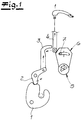
- the figures show a motor vehicle lock which, according to the exemplary embodiment and not by way of limitation, is a motor vehicle door lock.
- the motor vehicle door lock is provided and implemented on a rear side door of a motor vehicle or also on a sliding door, and this is likewise not restrictive.
- the basic structure of the motor vehicle lock or motor vehicle door lock in question initially has a locking mechanism 1, 2 composed of a rotary latch 1 and a pawl 2 interacting with it in the usual manner.
- an actuating lever chain 3, 4 is implemented.
- the actuating lever chain 3, 4 is composed, within the scope of the exemplary embodiment and not by way of limitation, from a release lever 3 on the one hand and an actuating lever 4 connected to an indicated handle on the other hand.
- a securing unit 5, 6 is also implemented.
- the securing unit 5, 6 for its part is composed of an actuating element 5 and a coupling lever or a spring unit 6. With the aid of the clutch lever or the spring unit 6, the actuating lever 4 closed or opened, as shown schematically in the Fig. 1 is indicated.
- the securing unit 5, 6 ensures that the actuating lever chain 3, 4 is set ineffective.
- the open position of the actuating lever 4 corresponds to this. Due to the interrupted actuating lever chain 3, 4, acting on the handle does not result in the locking pawl 2 being lifted from its engagement with the rotary latch 1 with the aid of the actuating lever 4 via the connected release lever 3. If, however, the securing unit 5, 6 is in its "off” position, the actuating lever chain 3, 4 is closed or activated. According to the Fig. 1 if the handle is acted on via the actuating lever 4, the triggering element or the triggering lever 3 is fastened upwards and, as a result, the pawl 2 is lifted from its engagement with the rotary latch 1.
- the actuating element 5 of the securing unit 5, 6 work mechanically or manually according to the exemplary embodiment.
- the adjusting element 5 is an actuating nut.
- the adjusting element 5 can also be equipped with a motor drive that is not expressly shown.
- the different and previously described functional positions of the securing unit 5, 6 correspond to the fact that the adjusting element or the actuating nut 5 is pivoted about its axis, like a further double arrow in FIG Fig. 1 indicates.
- the clutch lever connected to the actuating nut or the spring unit 6 is each engaged or disengaged in the exemplary embodiment.
- the spring unit 6 interacting with the actuating element 5 is implemented together with a cam 7 in order to define the two previously specified positions of the securing unit 5, 6.
- the design is within the scope of the variants according to the Figs. 2 to 4 each made so that the cam 7 is stationary and the spring or spring unit 6 is designed to be movable in relation to it. In principle, it is also possible to proceed in reverse, but this is not shown.
- the spring or the spring unit 6 is in each case designed as a surface element with surface pieces 6a, 6b that can be moved elastically against one another.
- the surface element or the spring or spring unit is made up of individual webs connected to one another.
- the surface element or the spring unit 6 is designed to be axially symmetrical in this case.
- the surface element is in each case coupled in a rotationally fixed manner to the actuating element 5, so that a pivoting movement about a common axis 8 of the spring unit 6 together with the actuating element 5 results in the spring unit 6 being moved relative to the stationary cam 7. Since in this case the spring unit 6 can have a projection 9 or the movement of the spring unit 6 relative to the cam 7 leads to an elastic deformation of the surface piece 6a relative to the surface piece 6b of the surface element, the change between the two positions of the securing unit 5 takes place, 6 particularly low-force.
- the two positions of the spring unit 6 actually correspond or the surface element to the in the Figs. 2 and 3 each indicated end positions.
- the spring unit 6 is designed as such made of steel, whereas the spring unit 6 of the variants according to the Figs. 2 and 3 is one made of plastic.
- the spring unit 6 may not only be connected to the actuating element 5 in a rotationally fixed manner, but can in principle also be molded onto the actuating element 5.
- the variant after the Fig. 4 proceeds in such a way that in this case the spring unit 6 is embedded with both of its ends in the actuating element 5 or an extension coupled thereto. In this case too, a relative movement of the spring or the spring unit 6 with respect to the stationary cam 7 leads to a change between the two positions of the safety unit 5, 6.
- the safety unit 5, 6 is designed as a child safety unit according to the exemplary embodiment and not in a restrictive manner.
- the design variants according to the Figures 5 and 6 proceed in such a way that the cams 7 including the spring unit 6 on the one hand interact with a contour 10 on the other hand.
- the overall design is such that the contour 10 is of fixed design, for example in a housing that accommodates or houses the motor vehicle lock.
- the relative movement between the cam 7 including the spring unit 6 on the one hand and the stationary contour 10 on the other hand is comparable to an unstable equilibrium and consequently particularly low-force between the two positions "on” and "off” of the securing unit 5, 6.
- the spring or spring unit 6 is designed as a spring bar connected on one side.
- the spring unit 6 or the spring bar is connected on one side to the actuating element 5, which in this case is designed as an actuating nut.
- the actuating nut or the adjusting element 5 was a plastic injection molded part on which both the Spring unit 6 can be designed as a spring bar just like the cam 7.
- the cam or extension 7 is not designed to be stationary, but is moved together with the actuating element 5.
- the spring or spring unit 6 is designed as a compression element.
- the spring unit 6 as a whole is enclosed by the actuating element 5 designed as an actuating nut.
- the cam 7 is moved and ensures the elastic deformation of the spring or spring unit 6, which in this case is designed as a compression element.
Landscapes
- Lock And Its Accessories (AREA)
Abstract
Description
- Die Erfindung betrifft ein Kraftfahrzeug-Schloss, insbesondere ein Kraftfahrzeug-Türschloss, mit einem Gesperre aus im wesentlichen Drehfalle und Sperrklinke, ferner mit einer Betätigungshebelkette zur Beaufschlagung des Gesperres, und mit einer Sicherungseinheit, welche in ihrer Stellung "ein" die Betätigungshebelkette unwirksam und in ihrer Stellung "aus" die Betätigungshebelkette wirksam setzt, wobei die Sicherungseinheit ein mechanisch und/oder motorisch arbeitendes Stellelement aufweist, und wobei eine mittelbar oder unmittelbar mit dem Stellelement wechselwirkende Federeinheit zur Einnahme der beiden Stellungen vorgesehen ist.
- Bei dem Kraftfahrzeug-Schloss handelte sich bevorzugt um ein Kraftfahrzeug-Türschloss, also ein Kraftfahrzeug-Schloss an oder in einer Kraftfahrzeug-Tür. Grundsätzlich kann das Kraftfahrzeug-Schloss aber auch an einem Kraftfahrzeugsitz oder einer Klappe angebracht sein. Bei der Klappe mag es sich um eine Tankklappe, eine Ladeklappe etc. handeln. Die Kraftfahrzeug-Tür kann grundsätzlich als Kraftfahrzeug-Seitentür, Kraftfahrzeug-Heckklappe, Kraftfahrzeugfronthaube, Kraftfahrzeug-Schiebetür usw. ausgebildet sein. Mithilfe der Sicherungseinheit lässt sich die Betätigungshebelkette zur Beauftragung des Gesperres unwirksam setzen. Das gilt für die Stellung "ein" der Sicherungseinheit.
- Meistens arbeitet hierzu die Sicherungseinheit auf ein Kupplungselement als Bestandteil der Betätigungshebelkette. In der Stellung "ein" der Sicherungseinheit wird das Kupplungselement "ausgekuppelt", so dass die Betätigungshebelkette mechanisch unterbrochen ist. Eine manuelle oder motorische Beaufschlagung der Betätigungshebelkette führt in diesem Fall nicht dazu, dass das Gesperre beaufschlagt wird. Das Gesperre behält folglich seine in der Regel eingenommene Position "verriegelt" bei.
- Soll jedoch das Gesperre geöffnet werden, so muss zunächst die Sicherungseinheit in ihrer Stellung "aus" überführt werden. Das korrespondiert typischerweise dazu, dass das Kupplungselement in die Position "ein gekuppelt" überführt wird. Als Folge hiervon ist die Betätigungshebelkette mechanisch geschlossen und führt eine manuelle oder motorische Beaufschlagung der Betätigungshebelkette in diesem Fall dazu, dass das Gesperre beaufschlagt und folglich geöffnet werden kann.
- Bei der Sicherungseinheit kann es sich generell um eine Verriegelungseinheit, eine Diebstahlsicherungseinheit oder auch eine Kindersicherungseinheit handeln. Das hängt letztlich davon ab, welche jeweilige Betätigungshebelkette mithilfe der Sicherungseinheit unwirksam bzw. wirksam gesetzt wird. Handelt es sich bei der Sicherungseinheit beispielhaft um eine Verriegelungseinheit, so erfolgt mithilfe der Sicherungseinheit typischerweise eine Außenverriegelung. D. h., die zugehörige Kraftfahrzeug-Tür lässt sich von außen nicht öffnen, wobei nach wie vor eine Öffnung von innen her möglich ist. Ist die Sicherungseinheit als Diebstahlsicherungseinheit ausgelegt, so erfolgt eine Innenverriegelung ebenso wie eine Außenvertretung, so dass die zugehörige Kraftfahrzeug-Tür auch bei beispielsweise eingeschlagener Fensterscheibe von innen her nicht geöffnet werden kann.
- Handelte sich schließlich bei der Sicherungseinheit um eine Kinder Sicherungseinheit, so sorgt diese lediglich an hinteren Kraftfahrzeug-Seitentüren dafür, dass an dieser Stelle eine Innenverriegelung vorliegt, die zugehörige hintere Kraftfahrzeug-Seitentür allerdings nach wie vor von außen geöffnet werden kann. Die sämtlichen Funktionsstellungen lassen sich dabei sowohl motorisch als auch manuell oder auch beides umsetzen und realisieren.
- So ist es beispielsweise bei einer Kindersicherungseinheit entsprechend der
DE 20 2004 010 218 U1 der Anmelderin möglich, die dortige Kindersicherungseinheit bzw. ein Innenverriegelungselement sowohl motorisch als auch über eine mechanische Schnittstelle zu beaufschlagen. Die mechanische Schnittstelle weist eine Betätigungsnuss mit Ausleger auf, welche über die zugehörige Schnittstelle ein mit einem Innenverriegelungselement unmittelbar wechselwirkendes Mitnahmeelement beaufschlagt. - Bei der gattungsbildenden Lehre nach der
DE 100 16 632 A1 ist erneut eine manuell betätigbaren Nuss realisiert, welche mit einem Kindersicherungssteller wechselwirkt, der seinerseits auch von einem Kindersicherungantrieb betätigt werden kann. Zusätzlich ist noch eine Feder bzw. ein Federelement realisiert, welches einen integralen Bestandteil eines Kupplungselementes darstellt. Das Kupplungselement ist durch Formgebung und Materialwahl des Kupplungselementes selbst realisiert. Dazu ist das Kupplungselement als aus Kunststoff bestehender Federhebel ausgeführt. - Die Einnahme der beiden Stellungen "ein" sowie "aus" der Sicherungseinheit bzw. Kindersicherungseinheit erfordert beim Stand der Technik eine mehr oder minder große Kraftbeaufschlagung, weil zum Teil eine Vielzahl an Hebeln der Betätigungshebelkette respektive als Bestandteil der Sicherungseinheit bewegt werden muss. Das ist insbesondere für den Fall nachteilig, dass eine rein mechanische Beaufschlagung beispielsweise einer Betätigungsnuss als Bestandteil der Sicherungseinheit erforderlich ist. Denn mithilfe einer solchen Betätigungnuss lässt sich nur sehr begrenzt ein ausreichendes Drehmoment zur Beauftragung der Sicherungseinheit übertragen. Hier will die Erfindung insgesamt Abhilfe schaffen.
- Der Erfindung liegt das technische Problem zugrunde, ein derartiges Kraftfahrzeug-Schloss und insbesondere Kraftfahrzeug-Türschloss so weiterzuentwickeln, dass insbesondere die Kraftverhältnisse optimiert sind und die Betätigung der Sicherungseinheit mit im Vergleich zum Stand der Technik verringerten Betätigungskräften möglich ist.
- Zur Lösung dieser technischen Problemstellung ist ein gattungsgemäßes Kraftfahrzeug-Schloss und insbesondere Kraftfahrzeug-Türschloss im Rahmen der Erfindung dadurch gekennzeichnet, dass die Federeinheit zusammen mit einem Nocken die beiden Stellungen definiert, wobei eine Relativbewegung zwischen dem Nocken und der Federeinheit oder zwischen dem Nocken inklusive Federeinheit und einer Kontur vergleichbar einem labilen Gleichgewicht für den Wechsel zwischen beiden Stellungen sorgt.
- Erfindungsgemäß tritt also zunächst einmal zu der Federeinheit ein Nocken hinzu, um die beiden Stellungen der Sicherungseinheit zu definieren. Bei den beiden Stellungen der Sicherungseinheit handelt es sich einerseits um die Position "ein" der Sicherungseinheit, welche in der Regel dazu führt, dass die Betätigungshebelkette unterbrochen ist und demzufolge eine Beaufschlagung der Betätigungshebelkette mit Blick auf das Gesperre leer geht. Demgegenüber korrespondiert die Stellung "aus" der Sicherungseinheit dazu, dass die Betätigungshebelkette geschlossen ist und das Gesperre beaufschlagt werden kann.
- Jedenfalls lassen sich diese beiden Stellungen im Rahmen der Erfindung mithilfe der Federeinheit in Verbindung mit dem Nocken realisieren und umsetzen. Dabei wird im Rahmen einer ersten Variante so vorgegangen, dass für den Wechsel zwischen den beiden Stellungen eine Relativbewegung zwischen dem Nocken und der Federeinheit vorgenommen wird. Diese Relativbewegung erfolgt dabei vergleichbar einem labilen Gleichgewicht und sorgt insgesamt für den Wechsel zwischen den beiden Stellungen. Die Vergleichbarkeit mit dem labilen Gleichgewicht führt erfindungsgemäß zu besonders geringen Bedienkräften. Denn die Vergleichbarkeit mit dem labilen Gleichgewicht drückt aus, dass bereits eine geringe Kraft zur Realisierung der Relativbewegung zwischen dem Nocken und der Federeinheit ausreicht, um die Sicherungseinheit insgesamt beispielsweise von ihrer zuvor eingenommenen Position "ein" in die gewünschte Position "aus", oder umgekehrt, zu überführen. Dadurch kann der Wechsel zwischen den beiden Stellungen problemlos auch per Hand über beispielsweise eine Betätigungsnuss als Stellelement oder Bestandteil des Stelleelementes vorgenommen werden.
- Vergleichbare geringe Betätigungskräfte beobachtet man für den Fall, dass eine Relativbewegung zwischen dem Nocken inklusive der Federeinheit einerseits und einer Kontur andererseits vorgenommen wird. Denn auch in diesem Fall kommt es vergleichbar einem labilen Gleichgewicht zu dem Wechsel zwischen den beiden Stellungen. In jedem Fall sorgt die kombinierte Wirkung aus der Federeinheit zusammen mit dem Nocken insgesamt dafür, dass der Wechsel zwischen den beiden Stellungen besonders kraftarm vorgenommen werden kann, vergleichbar einem labilen Gleichgewicht, bei dem bereits eine Störung der Position der Sicherungseinheit zu einer Veränderung ihrer Lage und damit der Einnahme der anderen korrespondierenden Stellung führt. Hierin sind die wesentlichen Vorteile zu sehen.
- Nach vorteilhafte Ausgestaltung ist die Auslegung so getroffen, dass der Nocken ortsfest und die Feder demgegenüber bewegbar ausgebildet ist. Es kann auch umgekehrt verfahren werden. In diesem Fall ist die Feder ortsfest und der Nocken demgegenüber bewegbar ausgebildet. Das gilt zumindest für die erste Variante, bei welcher eine Relativbewegung zwischen dem Nocken und der Federeinheit erfolgt und motorisch oder manuell vorgenommen wird, um den Wechsel zwischen den beiden Stellungen herbeizuführen.
- Bei der Variante, bei welcher die Relativbewegung zwischen dem Nocken inklusive Federeinheit einerseits und der Kontur andererseits vorgenommen wird, ist die Auslegung meistens so getroffen, dass die Feder und der Nocken bewegbar gegenüber der ortsfeste Kontur ausgebildet sind. Auch in diesem Fall ist eine grundsätzlich umgekehrte Vorgehensweise denkbar, dass nämlich die Feder und der Nocken ortsfest ausgebildet sind und demgegenüber die Kontur eine Bewegung vollführt. Im Regelfall wird jedoch so vorgegangen, dass die Feder und der Nocken gegenüber der ortsfeste Kontur bewegt werden, um den gewünschten Wechsel von der einen zur anderen Stellung herbeizuführen.
- Die Feder ist in der Regel an das Stellelement angeschlossen. Hier hat es sich bewährt, wenn die Feder und das Stellelement einstückig ausgebildet sind. Eine solche Ausführungsform empfiehlt sich besonders für den Fall, dass sowohl die Feder als auch das Stellelement aus beispielsweise Kunststoff gefertigt sind. Dadurch lässt sich die Feder besonders einfach und wirksam umsetzen und realisieren.
- Tatsächlich empfiehlt die Erfindung im Rahmen einer ersten Variante, dass die Feder als Flächenelement mit elastisch gegeneinander bewegbaren Flächenstücken ausgebildet ist. In diesem Zusammenhang kann das Flächenelement beispielsweise symmetrisch ausgelegt sein. Die beiden gegeneinander bewegbaren Flächenteile des Flächenelementes lassen sich für den Fall besonders realisieren und umsetzen, dass das fragliche Flächenelement aus miteinander verbundenen Stegen aufgebaut ist. Sofern einzelne dieser Stege unterbrochen sind, können hierdurch unschwer die elastisch gegeneinander bewegbaren Flächenstücke realisiert werden. Neben einer grundsätzlich symmetrischen Auslegung des Flächenelementes ist es natürlich ebenso auch möglich, das Flächenelement nicht symmetrisch bzw. asymmetrisch zu gestalten. Im Regelfall ist das Flächenelement jedoch meistens achsensymmetrisch aufgebaut.
- Darüber hinaus umfasst die Erfindung grundsätzlich auch Mischformen dergestalt, dass die Feder einerseits und das Stellelement andererseits nicht jeweils aus Kunststoff hergestellt sind, sondern auf unterschiedliche Materialien zurückgreifen. Beispielsweise kann die Feder als Stahlfeder ausgebildet sein. Diese Feder bzw. Stahlfeder kann dann ihrerseits mit einem Bauelement aus Kunststoff gekoppelt werden, indem beispielsweise beide Enden der Stahlfeder von dem Bauelement aus Kunststoff umschlossen sind. Bei dem Bauelement aus Kunststoff kann es sich um das Stellelement oder auch ein Gehäuse handeln. Insbesondere die letztgenannte Variante empfiehlt sich für den Fall, dass die Feder ortsfest ausgelegt ist und demgegenüber der Nocken bewegt wird.
- Eine andere Variante der Feder sieht vor, dass die Feder als einseitig angebundener Federsteg ausgelegt ist. Durch die einseitige Anbindung kann dieser Federsteg elastisch verformt werden. Meistens hat sich in diesem Fall eine Anbindung des Federsteges an eine Betätigungsnuss als Stellelement als besonders günstig erwiesen.
- Eine weitere dritte Ausführungsvariante der Feder sieht vor, dass die Feder als Kompressionselement ausgebildet ist. In diesem Fall handelt es sich bei der Feder um ein meistens aus Kunststoff hergestelltes Element, welches aufgrund der inhärenten Elastizität des eingesetzten Werkstoffes insgesamt als Kompressionselement fungiert. Sowohl die Variante mit der als Federsteg ausgebildeten Feder als auch diejenige, bei welcher die Feder als Kompressionselement ausgebildet ist, eignen sich besonders für den Fall, dass eine Relativbewegung zwischen dem Nocken inklusive Federeinheit einerseits und der zumeist ortsfesten Kontur andererseits erfolgt respektive vorgenommen wird, um einen Wechsel zwischen beiden möglichen Stellungen der Sicherungseinheit herbeizuführen.
- Bei der Sicherungseinheit handelt es sich bevorzugt um eine Kindersicherungseinheit, also eine Sicherungseinheit, welche typischerweise an hinteren Seitentüren oder auch an Schiebetüren in einem Kraftfahrzeug zum Einsatz kommt und meistens dafür sorgt, dass in der Stellung "ein" die fragliche Tür bzw. Kraftfahrzeug-Tür innen verriegelt ist. Die Beauftragung einer zugehörigen Innenhandhabe geht in diesem Fall also leer. Eine Außenhandhabe ist demgegenüber unverändert wirksam.
- Die Einnahme der Stellung "aus" der Sicherungseinheit bzw. Kindersicherungseinheit kann dabei motorisch dadurch erfolgen, dass ein Bediener einen entsprechenden Knopf am Armaturenbrett betätigt, um so die zuvor eingenommene Innenverriegelung aufzuheben und Passagieren in diesem Fall durch Beauftschlagung der in den Handhabe eine Öffnung der korrespondierenden Kraftfahrzeug-Tür zu erlauben. Der Wechsel zwischen den verschiedenen Stellungen der Kindersicherungseinheit im Beispielfall kann dabei auch mithilfe der bereits angesprochenen Betätigungsnuss vorgenommen werden, die sich in diesem Fall in respektive an der betreffenden Kraftfahrzeug-Tür findet.
- Im Ergebnis wird ein Kraftfahrzeug-Schloss und insbesondere Kraftfahrzeug-Türschloss zur Verfügung gestellt, welches sich durch einen besonders kraftarmen Wechsel zwischen den einzelnen Stellungen der Sicherungseinheit auszeichnet. Das lässt sich im Endeffekt darauf zurückführen, dass der Wechsel zwischen den beiden Stellungen vergleichbar einem labilen Gleichgewicht vorgenommen werden kann, also besonders geringe Betätigungskräfte erforderlich sind, das gilt sowohl für den Fall, dass die Sicherungseinheit motorisch beaufschlagt wird als auch insbesondere dann, wenn eine manuelle Beaufschlagung der Sicherungseinheit zum Wechsel zwischen den beiden Stellungen erfolgt. Hierin sind die wesentlichen Vorteile zu sehen.
- Im Folgenden wird die Erfindung anhand einer lediglich ein Ausführungsbeispiel darstellenden Zeichnung näher erläutert; es zeigen:
- Fig. 1
- Das erfindungsgemäße Kraftfahrzeug-Schloss in Gestalt eines Kraftfahrzeug-Türschlosses in einer schematischen Übersicht,
- Fig. 2
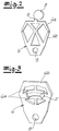
- die Federeinheit zusammen mit dem Nocken in einer ersten Variante,
- Fig. 3
- die Federeinheit inklusive Nocken in einer zweiten Variante,
- Fig. 4
- eine dritte Variante des Wechselspiels zwischen Federeinheit und Nocken,
- Fig. 5
- eine vierte Ausführungsvariante, bei welcher der Nocken inklusive Federeinheit einerseits und eine Kontur andererseits miteinander wechselwirken,
-
Fig. 6 eine weitere fünfte Variante des Ausführungsbeispiels nach derFig. 5 . - In den Figuren ist ein Kraftfahrzeug-Schloss dargestellt, bei dem es sich nach dem Ausführungsbeispiel und nicht einschränkend um ein Kraftfahrzeug-Türschloss handelt. Das Kraftfahrzeug-Türschloss ist im Beispielfall und ebenfalls nicht einschränkend an einer hinteren Seitentür eines Kraftfahrzeuges oder auch an einer Schiebetür vorgesehen und realisiert. Das fragliche Kraftfahrzeug-Schloss bzw. Kraftfahrzeug-Türschloss verfügt in seinem grundsätzlichen Aufbau zunächst einmal über ein Gesperre 1,2 aus einer Drehfalle 1 und einer hiermit in üblicher Art und Weise wechselwirkenden Sperrklinke 2. Darüber hinaus ist eine Betätigungshebelkette 3, 4 realisiert.
- Die Betätigungshebelkette 3, 4 setzt sich im Rahmen des Ausführungsbeispiels und nicht einschränkend aus einerseits einem Auslösehebel 3 und andererseits einem mit einer angedeuteten Handhabe verbundenen Betätigungshebel 4 zusammen. Außerdem ist noch eine Sicherungseinheit 5, 6 realisiert. Die Sicherungseinheit 5, 6 setzt sich ihrerseits aus einem Stellelement 5 und einem Kupplungshebel bzw. einer Federeinheit 6 zusammen. Mithilfe des Kupplungshebels bzw. der Federeinheit 6 kann der Betätigungshebel 4 geschlossen respektive geöffnet werden, wie dies schematisch in der
Fig. 1 angedeutet ist. - In der Stellung "ein" der Sicherungseinheit 5, 6 sorgt die Sicherungseinheit 5, 6 dafür, dass die Betätigungshebelkette 3, 4 unwirksam gesetzt ist. Hierzu korrespondiert die geöffnete Stellung des Betätigungshebels 4. Aufgrund der unterbrochenen Betätigungshebelkette 3, 4 führt folglich eine Beaufschlagung der Handhabe nicht dazu, dass mithilfe des Betätigungshebels 4 über den angeschlossenen Auslösehebel 3 die Sperrklinke 2 von ihrem Eingriff mit der Drehfalle 1 abgehoben werden kann. Befindet sich jedoch die Sicherungseinheit 5,6 in ihrer Position "aus", so ist die Betätigungshebelkette 3, 4 geschlossen bzw. wirksam gesetzt. Gemäß der
Fig. 1 führt eine Beaufschlagung der Handhabe über den Betätigungshebel 4 dazu, dass das Auslöseelement bzw. der Auslösehebel 3 aufwärts befestigt wird und dadurch die Sperrklinke 2 von ihrem Eingriff mit der Drehfalle 1 abhebt. - Das Stellelement 5 der Sicherungseinheit 5, 6 arbeiten nach dem Ausführungsbeispiel mechanisch bzw. manuell. Zu diesem Zweck handelt es sich bei dem Stellelement 5 um eine Betätigungsnuss. Grundsätzlich kann das Stellelement 5 auch mit einem nicht ausdrücklich dargestellten motorischen Antrieb ausgerüstet werden. Jedenfalls korrespondieren die unterschiedlichen und zuvor beschriebenen Funktionsstellungen der Sicherungseinheit 5, 6 dazu, dass das Stellelement bzw. die Betätigungsnuss 5 um ihre Achse verschwenkt wird, wie ein weiterer Doppelpfeil in der
Fig. 1 andeutet. Als Folge dieser unterschiedlichen Stellungen wird im Ausführungsbeispiel der an die Betätigungsnuss angeschlossene Kupplungshebel bzw. die Federeinheit 6 jeweils ein- oder ausgerückt. - In eingerückter bzw. eingekuppelter Stellung des Kupplungshebel bzw. der Federeinheit 6 ist die Betätigungshebelkette 3, 4 geschlossen. Hierzu korrespondiert die Stellung "aus" der Sicherungseinheit 5, 6. Befindet sich die Sicherungseinheit 5, 6 dagegen in ihrer Stellung "ein", so ist die Betätigungshebelkette 3, 4 unterbrochen.
- Erfindungsgemäß ist nun die mit dem Stellelement 5 wechselwirkende Federeinheit 6 zusammen mit einem Nocken 7 realisiert, um die beiden zuvor angegebenen Stellungen der Sicherungseinheit 5, 6 zu definieren. In den Ausführungsvarianten der
Fig. 2 bis 4 erfolgt dabei jeweils eine Relativbewegung zwischen dem Nocken 7 und der Federeinheit 6. Die Relativbewegung wird dabei vergleichbar einem labilen Gleichgewicht vorgenommen und sorgt dadurch für einen kraftarmen Wechsel zwischen beiden Stellungen der Sicherungseinheit 5, 6, also zwischen den Positionen "ein" und "aus". - Dabei ist die Auslegung im Rahmen der Varianten nach den
Fig. 2 bis 4 jeweils so getroffen, dass der Nocken 7 ortsfest und die Feder bzw. Federeinheit 6 demgegenüber bewegbar ausgebildet ist. Grundsätzlich kann auch umgekehrt vorgegangen werden, was jedoch nicht dargestellt ist. Bei den Ausführungsvarianten nach denFig. 2 und 3 ist die Feder bzw. die Federeinheit 6 jeweils als Flächenelement mit elastisch gegeneinander bewegbaren Flächenstücken 6a, 6b ausgebildet. Tatsächlich ist das Flächenelement bzw. die Feder bzw. Federeinheit aus einzelnen miteinander verbundenen Stegen aufgebaut. Außerdem ist das Flächenelement bzw. die Federeinheit 6 in diesem Fall achsensymmetrisch ausgelegt. Das Flächenelement ist dabei jeweils mit dem Stellelement 5 beispielsweise drehfest gekoppelt, so dass eine Schwenkbewegung um eine gemeinsame Achse 8 der Federeinheit 6 zusammen mit dem Stellelement 5 insgesamt dazu führt, dass die Federeinheit 6 gegenüber dem ortsfesten Nocken 7 bewegt wird. Da in diesem Fall die Federeinheit 6 über einen Vorsprung 9 verfügen kann bzw. die Bewegung der Federeinheit 6 gegenüber dem Nocken 7 zu einer elastischen Verformung des Flächenstückes 6a gegenüber dem Flächenstück 6b des Flächenelementes führt, erfolgt der Wechsel zwischen den beiden Stellungen der Sicherungseinheit 5, 6 besonders kraftarm. Tatsächlich korrespondieren die beiden Stellungen der Federeinheit 6 bzw. des Flächenelementes zu den in denFig. 2 und 3 jeweils angedeuteten Endpositionen. - Bei der Variante nach der
Fig. 4 ist die Federeinheit 6 als eine solche aus Stahl ausgebildet, wohingegen es sich bei der Federeinheit 6 der Varianten nach denFig. 2 und 3 um eine solche aus Kunststoff handelt. In diesem Fall mag die Federeinheit 6 nicht nur drehfest mit dem Stellelement 5 verbunden sein, sondern kann grundsätzlich auch an das Stellelement 5 angeformt werden. Die Variante nach derFig. 4 geht so vor, dass in diesem Fall die Federeinheit 6 mit ihren beiden Enden in das Stellelement 5 bzw. einen hiermit gekoppelten Fortsatz eingebettet ist. Auch in diesem Fall führt eine Relativbewegung der Feder bzw. der Federeinheit 6 gegenüber dem ortsfesten Nocken 7 zum Wechsel zwischen den beiden Stellungen der Sicherungseinheit 5, 6. Die Sicherungseinheit 5, 6 ist nach dem Ausführungsbeispiel und nicht einschränkend als Kindersicherungseinheit ausgebildet. - Die Ausführungsvarianten nach den
Fig. 5 und 6 gehen so vor, dass jeweils der Nocken 7 inklusive Federeinheit 6 einerseits mit einer Kontur 10 andererseits wechselwirken. Dabei ist die Auslegung insgesamt so getroffen, dass die Kontur 10 fest ausgebildet ist, beispielsweise in einem das Kraftfahrzeug-Schloss aufnehmenden bzw. einhausenden Gehäuse ausgebildet ist. Auch in diesem Fall erfolgt die Relativbewegung zwischen dem Nocken 7 inklusive Federeinheit 6 einerseits und der ortsfesten Kontur 10 andererseits vergleichbar einem labilen Gleichgewicht und demzufolge besonders kraftarm zwischen den beiden Stellungen "ein" und "aus" der Sicherungseinheit 5, 6. - Bei der Variante nach der
Fig. 5 ist die Feder bzw. Federeinheit 6 als einseitig angebundener Federsteg ausgelegt. In diesem Fall ist die Federeinheit 6 bzw. der Federsteg einseitig an das in diesem Fall als Betätigungsnuss ausgebildete Stellelement 5 angebunden. Bei der Betätigungsnuss bzw. dem Stellelement 5 handelte sich um ein Kunststoffspritzgussteil, an welchem unschwer sowohl die Federeinheit 6 als Federsteg ebenso wie der Nocken 7 ausgebildet werden können. D. h. bei den Beispielen derFig. 5 und 6 ist der Nocken bzw. Fortsatz 7 nicht ortsfest ausgelegt, sondern wird zusammen mit dem Stellelement 5 bewegt. - Die Variante nach der
Fig. 6 geht schließlich so vor, dass die Feder bzw. Federeinheit 6 als Kompressionselement ausgebildet ist. In diesem Fall wird die Federeinheit 6 insgesamt von dem als Betätigungsnuss ausgelegten Stellelement 5 umschlossen. Sobald die Federeinheit 6 inklusive Fortsatz 7 gegenüber der ortsfesten Kontur 10 beim Wechsel zwischen den beiden Stellungen hin und her bewegt wird, wird hierbei der Nocken 7 verfahren und sorgt für die elastische Verformung der in diesem Fall als Kompressionselement ausgebildeten Feder bzw. Federeinheit 6. -
- Drehfalle 1
- Sperrklinke 2
- Gesperre 1, 2
- Auslösehebel 3
- Betätigungshebelkette 3, 4
- Betätigungshebel 4
- Stellelement 5
- Betätigungsnuss 5
- Kupplungshebel 6
- Sicherungseinheit 5, 6
- Federeinheit 6
- Kupplungshebel 6
- Flächenstück 6a
- Flächenstück 6b
- Fortsatz, Nocken 7
- Achse 8
- Vorsprung 9
- Kontur 10
Claims (10)
- Kraftfahrzeug-Schloss, insbesondere Kraftfahrzeug-Türschloss, mit einem Gesperre (1, 2) aus im wesentlichen Drehfalle (1) und Sperrklinke (2), ferner mit einer Betätigungshebelkette (3, 4) zur Beaufschlagung des Gesperres (1, 2), und mit einer Sicherungseinheit (5, 6), welche in ihrer Stellung "ein" die Betätigungshebelkette (3, 4) unwirksam und in ihrer Stellung "aus" die Betätigungshebelkette (3, 4) wirksam setzt, wobei die Sicherungseinheit (5, 6 ein mechanisch und/oder motorisch arbeitendes Stellelement (5) aufweist, und wobei eine mittelbar oder unmittelbar mit dem Stellelement (5) wechselwirkende Federeinheit (6) zur Einnahme der beiden Stellungen vorgesehen ist,
dadurch gekennzeichnet, dass
die Federeinheit (6) zusammen mit einem Nocken (7) die beiden Stellungen definiert, wobei eine Relativbewegung zwischen dem Nocken (7) und der Federeinheit (6) oder zwischen dem Nocken (7) inklusive Federeinheit (7) und einer Kontur (10) vergleichbar einem labilen Gleichgewicht für den Wechsel zwischen beiden Stellungen sorgt. - Kraftfahrzeugschloss nach Anspruch 1, dadurch gekennzeichnet, dass der Nocken (7) ortsfest und die Federeinheit (6) demgegenüber bewegbar ausgebildet ist.
- Kraftfahrzeug-Schloss nach Anspruch eins, dadurch gekennzeichnet, dass die Federeinheit (6) ortsfest und der Nocken (7) demgegenüber bewegbar ausgebildet ist.
- Kraftfahrzeug-Schloss nach einem der Ansprüche 1 bis 3, dadurch gekennzeichnet, dass die Federeinheit (6) und der Nocken (7) bewegbar gegenüber der ortsfesten Kontur (10) ausgebildet sind.
- Kraftfahrzeug-Schloss nach einem der Ansprüche 1 bis 4, dadurch gekennzeichnet, dass die Federeinheit (6) an das Stellelement (5) angeschlossen ist.
- Kraftfahrzeug-Schloss nach Anspruch 5, dadurch gekennzeichnet, dass die Federeinheit (6) und das Stellelement (5) einstückig aus beispielsweise Kunststoff gefertigt sind.
- Kraftfahrzeug-Schloss nach einem der Ansprüche 1 bis 6, dadurch gekennzeichnet, dass die Federeinheit (6) als Flächenelement mit elastisch gegeneinander bewegbaren Flächenstücken (6a, 6b) ausgebildet ist
- Kraftfahrzeug-Schloss nach Anspruch 7, dadurch gekennzeichnet, dass das Flächenelement symmetrisch ausgebildet ist.
- Kraftfahrzeug-Schloss nach einem der Ansprüche 1 bis 8, dadurch gekennzeichnet, dass die Federeinheit (6) als einseitig angebundener Federsteg ausgebildet ist.
- Kraftfahrzeug-Schloss nach einem der Ansprüche 1 bis 9, dadurch gekennzeichnet, dass die Federeinheit (6) als Kompressionselement ausgebildet ist.
Applications Claiming Priority (1)
| Application Number | Priority Date | Filing Date | Title |
|---|---|---|---|
| DE102019131018.0A DE102019131018A1 (de) | 2019-11-18 | 2019-11-18 | Kraftfahrzeug-Schloss, insbesondere Kraftfahrzeug-Türschloss |
Publications (2)
| Publication Number | Publication Date |
|---|---|
| EP3822435A1 true EP3822435A1 (de) | 2021-05-19 |
| EP3822435B1 EP3822435B1 (de) | 2022-12-28 |
Family
ID=73401399
Family Applications (1)
| Application Number | Title | Priority Date | Filing Date |
|---|---|---|---|
| EP20207207.0A Active EP3822435B1 (de) | 2019-11-18 | 2020-11-12 | Kraftfahrzeug-schloss, insbesondere kraftfahrzeug-türschloss |
Country Status (2)
| Country | Link |
|---|---|
| EP (1) | EP3822435B1 (de) |
| DE (1) | DE102019131018A1 (de) |
Citations (6)
| Publication number | Priority date | Publication date | Assignee | Title |
|---|---|---|---|---|
| DE10016632A1 (de) | 2000-04-04 | 2001-10-18 | Bosch Gmbh Robert | Kraftfahrzeug-Türschloß mit elastisch auslenkbarem Kupplungselement |
| DE202004010218U1 (de) | 2004-06-29 | 2004-09-09 | Kiekert Ag | Kraftfahrzeugtürverschluss |
| WO2006054759A1 (en) * | 2004-11-17 | 2006-05-26 | Aisin Seiki Kabushiki Kaisha | Child protecting doorlock device |
| WO2016050236A1 (de) * | 2014-10-02 | 2016-04-07 | Kiekert Ag | Kraftfahrzeugtürverschluss |
| WO2018145693A1 (de) * | 2017-02-13 | 2018-08-16 | Kiekert Ag | Kraftfahrzeugtürschloss |
| WO2018219404A1 (de) * | 2017-05-30 | 2018-12-06 | Kiekert Ag | Schliesssystem mit drehbarem stellelement und federelement |
-
2019
- 2019-11-18 DE DE102019131018.0A patent/DE102019131018A1/de active Pending
-
2020
- 2020-11-12 EP EP20207207.0A patent/EP3822435B1/de active Active
Patent Citations (6)
| Publication number | Priority date | Publication date | Assignee | Title |
|---|---|---|---|---|
| DE10016632A1 (de) | 2000-04-04 | 2001-10-18 | Bosch Gmbh Robert | Kraftfahrzeug-Türschloß mit elastisch auslenkbarem Kupplungselement |
| DE202004010218U1 (de) | 2004-06-29 | 2004-09-09 | Kiekert Ag | Kraftfahrzeugtürverschluss |
| WO2006054759A1 (en) * | 2004-11-17 | 2006-05-26 | Aisin Seiki Kabushiki Kaisha | Child protecting doorlock device |
| WO2016050236A1 (de) * | 2014-10-02 | 2016-04-07 | Kiekert Ag | Kraftfahrzeugtürverschluss |
| WO2018145693A1 (de) * | 2017-02-13 | 2018-08-16 | Kiekert Ag | Kraftfahrzeugtürschloss |
| WO2018219404A1 (de) * | 2017-05-30 | 2018-12-06 | Kiekert Ag | Schliesssystem mit drehbarem stellelement und federelement |
Also Published As
| Publication number | Publication date |
|---|---|
| DE102019131018A1 (de) | 2021-05-20 |
| EP3822435B1 (de) | 2022-12-28 |
Similar Documents
| Publication | Publication Date | Title |
|---|---|---|
| EP2342405B1 (de) | Kraftfahrzeugschloss | |
| DE102008063318A1 (de) | Türschließvorrichtung für Fahrzeuge | |
| EP3994324B1 (de) | Kraftfahrzeug-türschloss | |
| EP3201411B1 (de) | Kraftfahrzeugtürverschluss | |
| DE102005000165A1 (de) | Schloss mit einem Schließzylinder | |
| EP4133152B1 (de) | Kraftfahrzeug-schloss | |
| WO2015024557A1 (de) | Kraftfahrzeugtürverschluss | |
| DE102022128469A1 (de) | Kraftfahrzeug-Schloss insbesondere Kraftfahrzeug-Türschloss | |
| EP4112851B1 (de) | Kraftfahrzeug-schloss, insbesondere kraftfahrzeug-türschloss | |
| DE202010013611U1 (de) | Kraftfahrzeugschloss | |
| EP4416355A1 (de) | Kraftfahrzeug-schloss insbesondere kraftfahrzeug-türschloss | |
| EP3822435B1 (de) | Kraftfahrzeug-schloss, insbesondere kraftfahrzeug-türschloss | |
| EP4555168A1 (de) | Kraftfahrzeug-schloss | |
| EP1619328B1 (de) | Kraftfahrzeugtürverschluss | |
| DE102019131180A1 (de) | Kraftfahrzeugschloss | |
| EP3901399B1 (de) | Kraftfahrzeugschloss | |
| EP4677179A1 (de) | Kraftfahrzeugschloss | |
| DE102023121757A1 (de) | Kraftfahrzeug-Schloss | |
| DE102021133115A1 (de) | Kraftfahrzeug-Schließeinrichtung | |
| DE102023110265A1 (de) | Kraftfahrzeug-Schloss | |
| DE102022122496A1 (de) | Kraftfahrzeug-Schloss | |
| EP4573257A1 (de) | Kombination aus einem kraftfahrzeugschloss und einer kraftfahrzeug-schloss-funktionseinheit | |
| DE102021120893A1 (de) | Zuzieheinrichtung für ein Kraftfahrzeugschloss | |
| WO2023232179A1 (de) | Kraftfahrzeug-schloss insbesondere kraftfahrzeug-türschloss | |
| WO2021098913A1 (de) | Kraftfahrzeug-türschloss |
Legal Events
| Date | Code | Title | Description |
|---|---|---|---|
| PUAI | Public reference made under article 153(3) epc to a published international application that has entered the european phase |
Free format text: ORIGINAL CODE: 0009012 |
|
| STAA | Information on the status of an ep patent application or granted ep patent |
Free format text: STATUS: REQUEST FOR EXAMINATION WAS MADE |
|
| 17P | Request for examination filed |
Effective date: 20201130 |
|
| AK | Designated contracting states |
Kind code of ref document: A1 Designated state(s): AL AT BE BG CH CY CZ DE DK EE ES FI FR GB GR HR HU IE IS IT LI LT LU LV MC MK MT NL NO PL PT RO RS SE SI SK SM TR |
|
| STAA | Information on the status of an ep patent application or granted ep patent |
Free format text: STATUS: EXAMINATION IS IN PROGRESS |
|
| 17Q | First examination report despatched |
Effective date: 20220228 |
|
| GRAP | Despatch of communication of intention to grant a patent |
Free format text: ORIGINAL CODE: EPIDOSNIGR1 |
|
| STAA | Information on the status of an ep patent application or granted ep patent |
Free format text: STATUS: GRANT OF PATENT IS INTENDED |
|
| GRAS | Grant fee paid |
Free format text: ORIGINAL CODE: EPIDOSNIGR3 |
|
| INTG | Intention to grant announced |
Effective date: 20221018 |
|
| GRAA | (expected) grant |
Free format text: ORIGINAL CODE: 0009210 |
|
| STAA | Information on the status of an ep patent application or granted ep patent |
Free format text: STATUS: THE PATENT HAS BEEN GRANTED |
|
| AK | Designated contracting states |
Kind code of ref document: B1 Designated state(s): AL AT BE BG CH CY CZ DE DK EE ES FI FR GB GR HR HU IE IS IT LI LT LU LV MC MK MT NL NO PL PT RO RS SE SI SK SM TR |
|
| REG | Reference to a national code |
Ref country code: GB Ref legal event code: FG4D Free format text: NOT ENGLISH |
|
| REG | Reference to a national code |
Ref country code: CH Ref legal event code: EP |
|
| REG | Reference to a national code |
Ref country code: DE Ref legal event code: R096 Ref document number: 502020002259 Country of ref document: DE |
|
| REG | Reference to a national code |
Ref country code: AT Ref legal event code: REF Ref document number: 1540575 Country of ref document: AT Kind code of ref document: T Effective date: 20230115 |
|
| REG | Reference to a national code |
Ref country code: IE Ref legal event code: FG4D Free format text: LANGUAGE OF EP DOCUMENT: GERMAN |
|
| REG | Reference to a national code |
Ref country code: LT Ref legal event code: MG9D |
|
| PG25 | Lapsed in a contracting state [announced via postgrant information from national office to epo] |
Ref country code: SE Free format text: LAPSE BECAUSE OF FAILURE TO SUBMIT A TRANSLATION OF THE DESCRIPTION OR TO PAY THE FEE WITHIN THE PRESCRIBED TIME-LIMIT Effective date: 20221228 Ref country code: NO Free format text: LAPSE BECAUSE OF FAILURE TO SUBMIT A TRANSLATION OF THE DESCRIPTION OR TO PAY THE FEE WITHIN THE PRESCRIBED TIME-LIMIT Effective date: 20230328 Ref country code: LT Free format text: LAPSE BECAUSE OF FAILURE TO SUBMIT A TRANSLATION OF THE DESCRIPTION OR TO PAY THE FEE WITHIN THE PRESCRIBED TIME-LIMIT Effective date: 20221228 Ref country code: FI Free format text: LAPSE BECAUSE OF FAILURE TO SUBMIT A TRANSLATION OF THE DESCRIPTION OR TO PAY THE FEE WITHIN THE PRESCRIBED TIME-LIMIT Effective date: 20221228 |
|
| REG | Reference to a national code |
Ref country code: NL Ref legal event code: MP Effective date: 20221228 |
|
| PG25 | Lapsed in a contracting state [announced via postgrant information from national office to epo] |
Ref country code: RS Free format text: LAPSE BECAUSE OF FAILURE TO SUBMIT A TRANSLATION OF THE DESCRIPTION OR TO PAY THE FEE WITHIN THE PRESCRIBED TIME-LIMIT Effective date: 20221228 Ref country code: LV Free format text: LAPSE BECAUSE OF FAILURE TO SUBMIT A TRANSLATION OF THE DESCRIPTION OR TO PAY THE FEE WITHIN THE PRESCRIBED TIME-LIMIT Effective date: 20221228 Ref country code: HR Free format text: LAPSE BECAUSE OF FAILURE TO SUBMIT A TRANSLATION OF THE DESCRIPTION OR TO PAY THE FEE WITHIN THE PRESCRIBED TIME-LIMIT Effective date: 20221228 Ref country code: GR Free format text: LAPSE BECAUSE OF FAILURE TO SUBMIT A TRANSLATION OF THE DESCRIPTION OR TO PAY THE FEE WITHIN THE PRESCRIBED TIME-LIMIT Effective date: 20230329 |
|
| PG25 | Lapsed in a contracting state [announced via postgrant information from national office to epo] |
Ref country code: NL Free format text: LAPSE BECAUSE OF FAILURE TO SUBMIT A TRANSLATION OF THE DESCRIPTION OR TO PAY THE FEE WITHIN THE PRESCRIBED TIME-LIMIT Effective date: 20221228 |
|
| P01 | Opt-out of the competence of the unified patent court (upc) registered |
Effective date: 20230529 |
|
| PG25 | Lapsed in a contracting state [announced via postgrant information from national office to epo] |
Ref country code: SM Free format text: LAPSE BECAUSE OF FAILURE TO SUBMIT A TRANSLATION OF THE DESCRIPTION OR TO PAY THE FEE WITHIN THE PRESCRIBED TIME-LIMIT Effective date: 20221228 Ref country code: RO Free format text: LAPSE BECAUSE OF FAILURE TO SUBMIT A TRANSLATION OF THE DESCRIPTION OR TO PAY THE FEE WITHIN THE PRESCRIBED TIME-LIMIT Effective date: 20221228 Ref country code: PT Free format text: LAPSE BECAUSE OF FAILURE TO SUBMIT A TRANSLATION OF THE DESCRIPTION OR TO PAY THE FEE WITHIN THE PRESCRIBED TIME-LIMIT Effective date: 20230428 Ref country code: ES Free format text: LAPSE BECAUSE OF FAILURE TO SUBMIT A TRANSLATION OF THE DESCRIPTION OR TO PAY THE FEE WITHIN THE PRESCRIBED TIME-LIMIT Effective date: 20221228 Ref country code: EE Free format text: LAPSE BECAUSE OF FAILURE TO SUBMIT A TRANSLATION OF THE DESCRIPTION OR TO PAY THE FEE WITHIN THE PRESCRIBED TIME-LIMIT Effective date: 20221228 |
|
| PG25 | Lapsed in a contracting state [announced via postgrant information from national office to epo] |
Ref country code: SK Free format text: LAPSE BECAUSE OF FAILURE TO SUBMIT A TRANSLATION OF THE DESCRIPTION OR TO PAY THE FEE WITHIN THE PRESCRIBED TIME-LIMIT Effective date: 20221228 Ref country code: PL Free format text: LAPSE BECAUSE OF FAILURE TO SUBMIT A TRANSLATION OF THE DESCRIPTION OR TO PAY THE FEE WITHIN THE PRESCRIBED TIME-LIMIT Effective date: 20221228 Ref country code: IS Free format text: LAPSE BECAUSE OF FAILURE TO SUBMIT A TRANSLATION OF THE DESCRIPTION OR TO PAY THE FEE WITHIN THE PRESCRIBED TIME-LIMIT Effective date: 20230428 Ref country code: AL Free format text: LAPSE BECAUSE OF FAILURE TO SUBMIT A TRANSLATION OF THE DESCRIPTION OR TO PAY THE FEE WITHIN THE PRESCRIBED TIME-LIMIT Effective date: 20221228 |
|
| REG | Reference to a national code |
Ref country code: DE Ref legal event code: R097 Ref document number: 502020002259 Country of ref document: DE |
|
| PG25 | Lapsed in a contracting state [announced via postgrant information from national office to epo] |
Ref country code: DK Free format text: LAPSE BECAUSE OF FAILURE TO SUBMIT A TRANSLATION OF THE DESCRIPTION OR TO PAY THE FEE WITHIN THE PRESCRIBED TIME-LIMIT Effective date: 20221228 |
|
| PLBE | No opposition filed within time limit |
Free format text: ORIGINAL CODE: 0009261 |
|
| STAA | Information on the status of an ep patent application or granted ep patent |
Free format text: STATUS: NO OPPOSITION FILED WITHIN TIME LIMIT |
|
| 26N | No opposition filed |
Effective date: 20230929 |
|
| PG25 | Lapsed in a contracting state [announced via postgrant information from national office to epo] |
Ref country code: SI Free format text: LAPSE BECAUSE OF FAILURE TO SUBMIT A TRANSLATION OF THE DESCRIPTION OR TO PAY THE FEE WITHIN THE PRESCRIBED TIME-LIMIT Effective date: 20221228 |
|
| PG25 | Lapsed in a contracting state [announced via postgrant information from national office to epo] |
Ref country code: IT Free format text: LAPSE BECAUSE OF FAILURE TO SUBMIT A TRANSLATION OF THE DESCRIPTION OR TO PAY THE FEE WITHIN THE PRESCRIBED TIME-LIMIT Effective date: 20221228 |
|
| REG | Reference to a national code |
Ref country code: CH Ref legal event code: PL |
|
| PG25 | Lapsed in a contracting state [announced via postgrant information from national office to epo] |
Ref country code: MC Free format text: LAPSE BECAUSE OF FAILURE TO SUBMIT A TRANSLATION OF THE DESCRIPTION OR TO PAY THE FEE WITHIN THE PRESCRIBED TIME-LIMIT Effective date: 20221228 |
|
| PG25 | Lapsed in a contracting state [announced via postgrant information from national office to epo] |
Ref country code: LU Free format text: LAPSE BECAUSE OF NON-PAYMENT OF DUE FEES Effective date: 20231112 |
|
| PG25 | Lapsed in a contracting state [announced via postgrant information from national office to epo] |
Ref country code: CH Free format text: LAPSE BECAUSE OF NON-PAYMENT OF DUE FEES Effective date: 20231130 |
|
| PG25 | Lapsed in a contracting state [announced via postgrant information from national office to epo] |
Ref country code: MC Free format text: LAPSE BECAUSE OF FAILURE TO SUBMIT A TRANSLATION OF THE DESCRIPTION OR TO PAY THE FEE WITHIN THE PRESCRIBED TIME-LIMIT Effective date: 20221228 Ref country code: LU Free format text: LAPSE BECAUSE OF NON-PAYMENT OF DUE FEES Effective date: 20231112 Ref country code: CH Free format text: LAPSE BECAUSE OF NON-PAYMENT OF DUE FEES Effective date: 20231130 |
|
| REG | Reference to a national code |
Ref country code: BE Ref legal event code: MM Effective date: 20231130 |
|
| REG | Reference to a national code |
Ref country code: IE Ref legal event code: MM4A |
|
| PG25 | Lapsed in a contracting state [announced via postgrant information from national office to epo] |
Ref country code: IE Free format text: LAPSE BECAUSE OF NON-PAYMENT OF DUE FEES Effective date: 20231112 |
|
| PG25 | Lapsed in a contracting state [announced via postgrant information from national office to epo] |
Ref country code: BE Free format text: LAPSE BECAUSE OF NON-PAYMENT OF DUE FEES Effective date: 20231130 |
|
| PG25 | Lapsed in a contracting state [announced via postgrant information from national office to epo] |
Ref country code: IE Free format text: LAPSE BECAUSE OF NON-PAYMENT OF DUE FEES Effective date: 20231112 Ref country code: BE Free format text: LAPSE BECAUSE OF NON-PAYMENT OF DUE FEES Effective date: 20231130 |
|
| PG25 | Lapsed in a contracting state [announced via postgrant information from national office to epo] |
Ref country code: BG Free format text: LAPSE BECAUSE OF FAILURE TO SUBMIT A TRANSLATION OF THE DESCRIPTION OR TO PAY THE FEE WITHIN THE PRESCRIBED TIME-LIMIT Effective date: 20221228 |
|
| PG25 | Lapsed in a contracting state [announced via postgrant information from national office to epo] |
Ref country code: BG Free format text: LAPSE BECAUSE OF FAILURE TO SUBMIT A TRANSLATION OF THE DESCRIPTION OR TO PAY THE FEE WITHIN THE PRESCRIBED TIME-LIMIT Effective date: 20221228 |
|
| GBPC | Gb: european patent ceased through non-payment of renewal fee |
Effective date: 20241112 |
|
| PG25 | Lapsed in a contracting state [announced via postgrant information from national office to epo] |
Ref country code: CY Free format text: LAPSE BECAUSE OF FAILURE TO SUBMIT A TRANSLATION OF THE DESCRIPTION OR TO PAY THE FEE WITHIN THE PRESCRIBED TIME-LIMIT; INVALID AB INITIO Effective date: 20201112 |
|
| PG25 | Lapsed in a contracting state [announced via postgrant information from national office to epo] |
Ref country code: HU Free format text: LAPSE BECAUSE OF FAILURE TO SUBMIT A TRANSLATION OF THE DESCRIPTION OR TO PAY THE FEE WITHIN THE PRESCRIBED TIME-LIMIT; INVALID AB INITIO Effective date: 20201112 |
|
| PG25 | Lapsed in a contracting state [announced via postgrant information from national office to epo] |
Ref country code: GB Free format text: LAPSE BECAUSE OF NON-PAYMENT OF DUE FEES Effective date: 20241112 |
|
| PG25 | Lapsed in a contracting state [announced via postgrant information from national office to epo] |
Ref country code: TR Free format text: LAPSE BECAUSE OF FAILURE TO SUBMIT A TRANSLATION OF THE DESCRIPTION OR TO PAY THE FEE WITHIN THE PRESCRIBED TIME-LIMIT Effective date: 20221228 |
|
| PGFP | Annual fee paid to national office [announced via postgrant information from national office to epo] |
Ref country code: DE Payment date: 20251118 Year of fee payment: 6 |
|
| PGFP | Annual fee paid to national office [announced via postgrant information from national office to epo] |
Ref country code: AT Payment date: 20260113 Year of fee payment: 5 |
|
| PGFP | Annual fee paid to national office [announced via postgrant information from national office to epo] |
Ref country code: FR Payment date: 20251120 Year of fee payment: 6 |
|
| PGFP | Annual fee paid to national office [announced via postgrant information from national office to epo] |
Ref country code: CZ Payment date: 20251106 Year of fee payment: 6 |
|
| PG25 | Lapsed in a contracting state [announced via postgrant information from national office to epo] |
Ref country code: MT Free format text: LAPSE BECAUSE OF NON-PAYMENT OF DUE FEES Effective date: 20231112 |