EP3815520A1 - Handgeführtes bearbeitungsgerät mit radialgebläse - Google Patents
Handgeführtes bearbeitungsgerät mit radialgebläse Download PDFInfo
- Publication number
- EP3815520A1 EP3815520A1 EP19205812.1A EP19205812A EP3815520A1 EP 3815520 A1 EP3815520 A1 EP 3815520A1 EP 19205812 A EP19205812 A EP 19205812A EP 3815520 A1 EP3815520 A1 EP 3815520A1
- Authority
- EP
- European Patent Office
- Prior art keywords
- wall
- section
- hand
- processing device
- air flow
- Prior art date
- Legal status (The legal status is an assumption and is not a legal conclusion. Google has not performed a legal analysis and makes no representation as to the accuracy of the status listed.)
- Granted
Links
Images



Classifications
-
- F—MECHANICAL ENGINEERING; LIGHTING; HEATING; WEAPONS; BLASTING
- F04—POSITIVE - DISPLACEMENT MACHINES FOR LIQUIDS; PUMPS FOR LIQUIDS OR ELASTIC FLUIDS
- F04D—NON-POSITIVE-DISPLACEMENT PUMPS
- F04D29/00—Details, component parts, or accessories
- F04D29/40—Casings; Connections of working fluid
- F04D29/42—Casings; Connections of working fluid for radial or helico-centrifugal pumps
- F04D29/44—Fluid-guiding means, e.g. diffusers
- F04D29/441—Fluid-guiding means, e.g. diffusers especially adapted for elastic fluid pumps
-
- A—HUMAN NECESSITIES
- A01—AGRICULTURE; FORESTRY; ANIMAL HUSBANDRY; HUNTING; TRAPPING; FISHING
- A01B—SOIL WORKING IN AGRICULTURE OR FORESTRY; PARTS, DETAILS, OR ACCESSORIES OF AGRICULTURAL MACHINES OR IMPLEMENTS, IN GENERAL
- A01B71/00—Construction or arrangement of setting or adjusting mechanisms, of implement or tool drive or of power take-off; Means for protecting parts against dust, or the like; Adapting machine elements to or for agricultural purposes
-
- E—FIXED CONSTRUCTIONS
- E01—CONSTRUCTION OF ROADS, RAILWAYS, OR BRIDGES
- E01H—STREET CLEANING; CLEANING OF PERMANENT WAYS; CLEANING BEACHES; DISPERSING OR PREVENTING FOG IN GENERAL CLEANING STREET OR RAILWAY FURNITURE OR TUNNEL WALLS
- E01H1/00—Removing undesirable matter from roads or like surfaces, with or without moistening of the surface
- E01H1/08—Pneumatically dislodging or taking-up undesirable matter or small objects; Drying by heat only or by streams of gas; Cleaning by projecting abrasive particles
- E01H1/0809—Loosening or dislodging by blowing ; Drying by means of gas streams
-
- A—HUMAN NECESSITIES
- A01—AGRICULTURE; FORESTRY; ANIMAL HUSBANDRY; HUNTING; TRAPPING; FISHING
- A01G—HORTICULTURE; CULTIVATION OF VEGETABLES, FLOWERS, RICE, FRUIT, VINES, HOPS OR SEAWEED; FORESTRY; WATERING
- A01G20/00—Cultivation of turf, lawn or the like; Apparatus or methods therefor
- A01G20/40—Apparatus for cleaning the lawn or grass surface
- A01G20/43—Apparatus for cleaning the lawn or grass surface for sweeping, collecting or disintegrating lawn debris
- A01G20/47—Vacuum or blower devices
-
- A—HUMAN NECESSITIES
- A47—FURNITURE; DOMESTIC ARTICLES OR APPLIANCES; COFFEE MILLS; SPICE MILLS; SUCTION CLEANERS IN GENERAL
- A47L—DOMESTIC WASHING OR CLEANING; SUCTION CLEANERS IN GENERAL
- A47L5/00—Structural features of suction cleaners
- A47L5/12—Structural features of suction cleaners with power-driven air-pumps or air-compressors, e.g. driven by motor vehicle engine vacuum
- A47L5/22—Structural features of suction cleaners with power-driven air-pumps or air-compressors, e.g. driven by motor vehicle engine vacuum with rotary fans
-
- F—MECHANICAL ENGINEERING; LIGHTING; HEATING; WEAPONS; BLASTING
- F04—POSITIVE - DISPLACEMENT MACHINES FOR LIQUIDS; PUMPS FOR LIQUIDS OR ELASTIC FLUIDS
- F04D—NON-POSITIVE-DISPLACEMENT PUMPS
- F04D25/00—Pumping installations or systems
- F04D25/02—Units comprising pumps and their driving means
- F04D25/08—Units comprising pumps and their driving means the working fluid being air, e.g. for ventilation
- F04D25/084—Units comprising pumps and their driving means the working fluid being air, e.g. for ventilation hand fans
-
- F—MECHANICAL ENGINEERING; LIGHTING; HEATING; WEAPONS; BLASTING
- F04—POSITIVE - DISPLACEMENT MACHINES FOR LIQUIDS; PUMPS FOR LIQUIDS OR ELASTIC FLUIDS
- F04D—NON-POSITIVE-DISPLACEMENT PUMPS
- F04D29/00—Details, component parts, or accessories
- F04D29/40—Casings; Connections of working fluid
- F04D29/42—Casings; Connections of working fluid for radial or helico-centrifugal pumps
- F04D29/4206—Casings; Connections of working fluid for radial or helico-centrifugal pumps especially adapted for elastic fluid pumps
-
- F—MECHANICAL ENGINEERING; LIGHTING; HEATING; WEAPONS; BLASTING
- F04—POSITIVE - DISPLACEMENT MACHINES FOR LIQUIDS; PUMPS FOR LIQUIDS OR ELASTIC FLUIDS
- F04D—NON-POSITIVE-DISPLACEMENT PUMPS
- F04D29/00—Details, component parts, or accessories
- F04D29/40—Casings; Connections of working fluid
- F04D29/42—Casings; Connections of working fluid for radial or helico-centrifugal pumps
- F04D29/4206—Casings; Connections of working fluid for radial or helico-centrifugal pumps especially adapted for elastic fluid pumps
- F04D29/422—Discharge tongues
-
- F—MECHANICAL ENGINEERING; LIGHTING; HEATING; WEAPONS; BLASTING
- F04—POSITIVE - DISPLACEMENT MACHINES FOR LIQUIDS; PUMPS FOR LIQUIDS OR ELASTIC FLUIDS
- F04D—NON-POSITIVE-DISPLACEMENT PUMPS
- F04D29/00—Details, component parts, or accessories
- F04D29/40—Casings; Connections of working fluid
- F04D29/42—Casings; Connections of working fluid for radial or helico-centrifugal pumps
- F04D29/4206—Casings; Connections of working fluid for radial or helico-centrifugal pumps especially adapted for elastic fluid pumps
- F04D29/4226—Fan casings
-
- F—MECHANICAL ENGINEERING; LIGHTING; HEATING; WEAPONS; BLASTING
- F04—POSITIVE - DISPLACEMENT MACHINES FOR LIQUIDS; PUMPS FOR LIQUIDS OR ELASTIC FLUIDS
- F04D—NON-POSITIVE-DISPLACEMENT PUMPS
- F04D29/00—Details, component parts, or accessories
- F04D29/40—Casings; Connections of working fluid
- F04D29/42—Casings; Connections of working fluid for radial or helico-centrifugal pumps
- F04D29/44—Fluid-guiding means, e.g. diffusers
- F04D29/441—Fluid-guiding means, e.g. diffusers especially adapted for elastic fluid pumps
- F04D29/444—Bladed diffusers
-
- F—MECHANICAL ENGINEERING; LIGHTING; HEATING; WEAPONS; BLASTING
- F04—POSITIVE - DISPLACEMENT MACHINES FOR LIQUIDS; PUMPS FOR LIQUIDS OR ELASTIC FLUIDS
- F04D—NON-POSITIVE-DISPLACEMENT PUMPS
- F04D29/00—Details, component parts, or accessories
- F04D29/66—Combating cavitation, whirls, noise, vibration or the like; Balancing
- F04D29/661—Combating cavitation, whirls, noise, vibration or the like; Balancing especially adapted for elastic fluid pumps
- F04D29/663—Sound attenuation
-
- F—MECHANICAL ENGINEERING; LIGHTING; HEATING; WEAPONS; BLASTING
- F04—POSITIVE - DISPLACEMENT MACHINES FOR LIQUIDS; PUMPS FOR LIQUIDS OR ELASTIC FLUIDS
- F04D—NON-POSITIVE-DISPLACEMENT PUMPS
- F04D29/00—Details, component parts, or accessories
- F04D29/66—Combating cavitation, whirls, noise, vibration or the like; Balancing
- F04D29/661—Combating cavitation, whirls, noise, vibration or the like; Balancing especially adapted for elastic fluid pumps
- F04D29/663—Sound attenuation
- F04D29/665—Sound attenuation by means of resonance chambers or interference
-
- F—MECHANICAL ENGINEERING; LIGHTING; HEATING; WEAPONS; BLASTING
- F05—INDEXING SCHEMES RELATING TO ENGINES OR PUMPS IN VARIOUS SUBCLASSES OF CLASSES F01-F04
- F05D—INDEXING SCHEME FOR ASPECTS RELATING TO NON-POSITIVE-DISPLACEMENT MACHINES OR ENGINES, GAS-TURBINES OR JET-PROPULSION PLANTS
- F05D2250/00—Geometry
- F05D2250/50—Inlet or outlet
- F05D2250/52—Outlet
Definitions
- the invention relates to a hand-held machining device with a radial fan.
- processing devices are used, for example, as hand-held, motor-driven gardening or forestry processing devices, such as hedge trimmers, hedge trimmers, brushcutters, pole pruners, leaf blowers, sweepers, power saws, lawn mowers and scarifiers, with an internal combustion engine or a battery-powered electric motor serving as the motor drive.
- the radial fan is used, for example, to supply cooling air to an internal combustion engine or an electric motor or to provide suction air or blown air for suction or blowing devices.
- the laid-open specification discloses DE 102 45 418 A1 a special radial fan for cooling an internal combustion engine, and the laid-open specification DE 10 2005 003 275 A1 discloses a special radial blower for a backpack suction / blowing device.
- the technical problem underlying the invention is the provision of a hand-held processing device of the type mentioned at the outset which, compared to conventional devices of this type, enables operation with relatively low noise emissions, in particular with regard to its radial fan.
- the invention solves this problem by providing a hand-held processing device with the features of claim 1.
- the radial fan comprises a fan wheel and an air duct, which comprises a spiral section surrounding the fan wheel with a channel cross-section increasing in the air flow direction and an outlet funnel section adjoining the spiral section, which widens in a funnel shape in the air flow direction, with a radially inner boundary wall and a radially outer boundary wall, the Outlet funnel section ends in an air outlet opening, the outlet width of which is smaller than an outer diameter of the fan wheel.
- the radially inner and / or the radially outer boundary wall of the outlet funnel section has a curvature in the opposite direction to the spiral section, and an intermediate wall is arranged in the outlet funnel section between the radially inner and the radially outer boundary wall, the intermediate wall being curved in the opposite direction to the spiral section and the outlet funnel section divided into two sections each widening in the shape of a funnel in the air flow direction.
- the processing device causes only comparatively low fan-induced noise emissions, in particular lower noise emissions than with conventional radial fans without a partition or with different partition wall configurations or different configurations of the spiral section surrounding the fan wheel and the outlet funnel section adjoining the spiral section, as this is also verified experimentally could.
- the noise emission caused by the fan which is minimized in this way, advantageously creates the prerequisites for improving the overall acoustic quality of the device in comparison to the prior art and for giving the device overall high-quality acoustics during operation.
- the air flow provided by it contribute in particular to the measures to arrange the partition in the outlet funnel section between its two radial boundary walls, to give the intermediate wall a curvature in the opposite direction to the spiral section and the outlet funnel section through the intermediate wall into the two Divide subsections so that each subsection in turn widens in a funnel-shaped manner in the air flow direction.
- This is how it comes in that Area of the outlet funnel section in which the partition is arranged, neither by the course of the two radial boundary walls nor by the course of the partition to reduce the air flow cross section in the air flow direction. Rather, the air passage cross-section increases continuously, preferably steadily, in the air flow direction in each of the two subsections due to their funnel-shaped expansion.
- an inner transverse distance of the partition from the radially inner boundary wall and an outer transverse distance of the partition from the radially outer boundary wall are the same or differ by a maximum of 10%, preferably a maximum of 5%, i.e. the larger transverse distance is then at most 10% or 5% larger than the smaller transverse distance.
- the partition is arranged differently, e.g. with significantly different transverse distances to the two radial boundary walls.
- an inner cross-sectional area between the intermediate wall and the radially inner boundary wall and an outer cross-sectional area between the intermediate wall and the radially outer boundary wall are the same size or differ by at most 10%, in particular at most 5%. It turns out that this equal-area division of the cross-sectional area radially delimited by the radially inner and radially outer boundary wall in the outlet funnel section, which is available for the air flow, has a particularly favorable influence on the reduction of the air flow noise due to the partition wall.
- the partition is arranged differently with the formation of significantly different cross-sectional areas.
- the wall thickness of the intermediate wall is constant transversely to the air flow direction, or a largest wall thickness is at most 10% greater than a smallest wall thickness.
- the partition wall is in Air flow direction extends with constant or in any case only slightly fluctuating wall thickness, which avoids corresponding wall-related flow noises.
- the wall thickness of the intermediate wall varies to a greater extent in its course in the air flow direction, for example in the form of a wedge-shaped increase in the wall thickness in the air flow direction.
- the partition wall ends flush with the air outlet opening in the air flow direction or ends at a distance in front of it which is at most 10% of its length in the air flow direction and / or at most twice its wall thickness. It turns out that this arrangement of the partition wall is also conducive to reducing the flow noises caused by the radial fan.
- the partition wall ends at a greater distance in front of the air outlet opening, e.g. at a distance of more than 10% of the partition wall length in the air flow direction or of more than twice the partition wall thickness.
- the intermediate wall extends with an upstream wall side edge into a transition area of the spiral section and the outlet funnel section. This measure also proves to be very advantageous for minimizing the noise emissions caused by the fan.
- the partition wall in the air flow direction does not begin in this transition area, but at a downstream distance from this in the outlet funnel section.
- the radially inner and / or the radially outer boundary wall of the outlet funnel section continues counter to the air flow direction into the spiral section and changes its sense of curvature in a transition area of the spiral section and the outlet funnel section. This measure also proves to be very advantageous for reducing the noise emissions caused by the fan.
- the radially outer boundary wall continues around the entire circumference of the fan wheel in the spiral section and forms a radially outer boundary wall of the same in the spiral section of the air duct, wherein it at its upstream end with the radially inner boundary wall of the outlet funnel section combined.
- each of the two radial boundary walls of the outlet funnel section or at least the radially inner boundary wall does not continue into the spiral section and / or does not change the direction of curvature in the transition area.
- the intermediate wall is designed to be closed without perforations. This means that there is no air flow connection between the two partial sections, into which the outlet funnel section is divided by the partition, through the partition. This also helps to minimize airflow noise from the fan.
- the intermediate wall is formed by a perforated wall.
- At least one of the intermediate wall, the radially inner boundary wall and the radially outer boundary wall has a sound-absorbing surface and / or is formed from a sound-absorbing material, with sound-absorbing also being understood in the broad sense of the word to be sound-reducing. Due to the sound-absorbing surface or the sound-absorbing material, the respective wall, ie the partition and / or the radially inner boundary wall and / or the radially outer boundary wall, is able to act accordingly as a sound-absorbing element and thereby additionally contribute to minimizing the air flow noise .
- the respective wall has a surface that has no sound insulation properties, or the wall is formed from a material without sound absorbing properties.
- the machining device has a machining tool, an electric drive motor for the machining tool and / or for the radial fan and a cooling air duct for the drive motor, the radial fan being arranged in the cooling air duct.
- the use of the electric drive motor results in reduced engine operating noises compared to the use of an internal combustion engine, and the radial fan enables the electric drive motor to be effectively cooled with cooling air at the same time low noise emissions from the radial fan.
- the machining device has an internal combustion engine as the drive motor for the machining tool and / or for the radial fan.
- the invention also includes an embodiment in which the intermediate wall is represented by a plurality of individual walls which are spaced apart from one another in the outlet funnel section between the radially inner and the radially outer boundary wall and run with a curvature in the opposite direction to the spiral section and the outlet funnel section in a corresponding number of more than divide two sections each widening in a funnel shape in the air flow direction.
- the individual partition walls are preferably equidistantly spaced, and / or the subsections have cross-sectional areas of the same size or only slightly different from one another.
- Hand-held processing device shown in exemplary implementations can in particular be a hand-held gardening or forestry processing device and includes a radial fan 1, which, as shown in FIGS Fig. 4 and 5 can be seen more precisely, an impeller 2 and an air duct 3, which has a spiral section 3a surrounding the fan wheel 2 with a channel cross-section Qk increasing in the air flow direction LR and an outlet funnel section 3b that adjoins the spiral section 3a and widens in a funnel shape in the air flow direction LR with a radially inner boundary wall 4a and a radially outer boundary wall 4b.
- the outlet funnel section 3b ends in an air outlet opening 6, the outlet width AB of which is smaller than an outer diameter Dg of the fan wheel 2.
- the radially inner boundary wall 4a and / or the radially outer boundary wall 4b of the outlet funnel section 3b has a curvature in the opposite direction to the spiral section 3a.
- Both boundary walls 4a, 4b have an opposite curvature to the spiral section 3a, more precisely the spiral section a clockwise curvature and the two boundary walls 4a, 4b of the outlet funnel section 3b a counterclockwise curvature.
- the air duct 3 can in particular be formed by a corresponding design of a fan housing 1a in its interior, the fan wheel 2 being rotatably inserted into the fan housing 1a and the fan housing 1a being composed, for example, of two housing half-shells connected to one another, as in the embodiment shown.
- an intermediate wall 5 is arranged between the radially inner delimiting wall 4a and the radially outer delimiting wall 4b, which extends with a curvature in the opposite direction to the spiral section 3a, ie in Fig. 4 with a counterclockwise curvature, and divides the outlet funnel section 3b into two subsections 8a, 8b each widening in a funnel shape in the air flow direction LR.
- the processing device includes in corresponding versions Figs. 1 to 3 a machining tool 11, an electric drive motor 9 for the machining tool 11 and / or the radial fan 1 and a cooling air duct 10 for the drive motor 9, the radial fan 1 in the Cooling air guide 10 is arranged.
- the processing device contains an internal combustion engine as the drive motor instead of the electric drive motor 9.
- the drive motor 9 is located in a motor housing 13 in which the cooling air duct 10 extends from an air inlet 12 into the housing 13 to the air outlet opening 6 from the radial fan 1 or from the motor housing 13.
- the drive motor 9 and optionally other device components to be cooled are located in the cooling air duct 10, and the radial fan 1 provides the necessary cooling air flow, whereby it is preferably driven by the drive motor 9, or alternatively by another drive.
- the machining device is of the so-called shaft type, in which the machining tool 11 is connected to the motor housing 13 via a device shaft 14 and a drive shaft leads from the drive motor 9 to the machining tool 11 through the shaft 14.
- the machining device is of a shaftless type, in which, for example, the machining tool 11 is positioned in the motor housing 13 or directly adjoining it.
- an inner transverse distance QA1 of the partition 5 from the radially inner boundary wall 4a and an outer transverse distance QA2 of the partition 5 from the radially outer boundary wall 4b are the same or differ by at most 10%, in preferred implementations by at most 5%. It goes without saying that the two transverse distances QA1, QA2 each relate to the same point on the partition 5 along its longitudinal extension, in FIG Fig. 4 given as an example for a point Pz, since both transverse distances QA1, QA2 increase in the air flow direction due to the funnel-shaped widening of both subsections 8a, 8b.
- an inner cross-sectional area QF1 between the intermediate wall 5 and the radially inner boundary wall 4a and an outer cross-sectional area QF2 between the intermediate wall 5 and the radially outer boundary wall 4b are the same size or differ by no more than 10%, in particular no more than 5%, also here again based on the same point on the partition 5 along its longitudinal extension.
- the outlet funnel section 3b is divided by the partition 5 into the two flow-technically parallel subsections 8a, 8b with essentially the same or at least not very different flow cross-sections, the two subsections 8a, 8b in their course in the air flow direction LR this in Essentially the same or not very different flow cross-sections are mutually maintained, while the flow cross-section of each of the two subsections 8a, 8b per se increases continuously, preferably steadily, in the air flow direction LR due to the funnel-shaped expansion.
- the partition 5 is arranged offset noticeably towards one of the two radial boundary walls 4a, 4b of the outlet funnel section 3b.
- the wall thickness Wd of the intermediate wall 5 is constant transversely to the air flow direction LR.
- the wall thickness Wd is not constant, but fluctuates by a maximum of 10%.
- the partition 5 ends flush with the air outlet opening 6 in the air flow direction LR or ends in front of it at a distance Aw that is greater than zero, but at most 10% of the length WL of the partition 5 in the air flow direction LR and / or at most that Twice the wall thickness Wd of the intermediate wall 5, as in the exemplary embodiment shown. In alternative embodiments, the partition 5 ends at a greater distance Aw in front of the air outlet opening 6.
- the wall thickness Wd of the partition 5 is at most 5% of the outlet width AB of the air outlet opening 4, as in the exemplary embodiment shown. For some applications, it may alternatively be desired to select a larger wall thickness Wd of the partition 5.
- the partition 5 extends with an upstream wall side edge 5a into a transition area 7 of the spiral section 3a and the outlet funnel section 3b. It turns out that this extension of the partition wall 5, which extends relatively far in the direction of the spiral section 3a into the air duct 3, is very advantageous for the desired minimization of noise.
- the radially inner and / or the radially outer boundary wall 4a, 4b of the outlet funnel section 3b continues counter to the air flow direction LR into the spiral section 3a and changes its sense of curvature in the transition area 7.
- the radially inner boundary wall 4a extends into the spiral section 3a as far as an inflow-side end edge 15 and changes its sense of curvature at an associated turning point W1 in the transition region 7.
- the radially outer boundary wall 4b continues into the entire spiral section 3a around the fan wheel 2 and unites at a junction VP with the radially inner boundary wall 4a.
- the outer boundary wall 4b changes its direction of curvature at a turning point W2 in the transition area 7.
- an alternative implementation may be desirable in which the radial boundary walls 4a, 4b do not change their direction of curvature in the transition area 7 or do not merge into the spiral section 3a continue, in particular the radially inner boundary wall 4a.
- the intermediate wall 5 is designed to be closed without perforation, as in the embodiment shown, i.e. the intermediate wall 5 has no openings between the two partial sections 8a, 8b into which it divides the outlet funnel section 3b.
- the intermediate wall 5 is formed as a perforated wall with one or more perforation openings.
- the partition 5, as in the example shown, has a sound-absorbing surface 5b and / or is formed from a sound-absorbing material. Suitable surface coatings or surface profiles and suitable wall materials to provide this sound insulation characteristic are known per se for such purposes, which therefore does not require any further explanation here.
- the partition 5 can be formed from a non-sound-absorbing material without a sound-absorbing surface.
- the invention provides a hand-held processing device which is optimized in a very advantageous manner with regard to the low noise emission of its radial fan.
- the processing device can in particular be a hand-held gardening or forestry processing device of any conventional type, provided that a radial fan is used in it.
Landscapes
- Engineering & Computer Science (AREA)
- Mechanical Engineering (AREA)
- General Engineering & Computer Science (AREA)
- Life Sciences & Earth Sciences (AREA)
- Environmental Sciences (AREA)
- Soil Sciences (AREA)
- Architecture (AREA)
- Civil Engineering (AREA)
- Structural Engineering (AREA)
- Structures Of Non-Positive Displacement Pumps (AREA)
Abstract
2.1. Die Erfindung bezieht sich auf ein handgeführtes Bearbeitungsgerät mit einem Radialgebläse (1).
2.2. Beim erfindungsgemäßen Bearbeitungsgerät umfasst das Radialgebläse (1) ein Gebläserad (2) und einen Luftkanal (3), der einen das Gebläserad (2) umgebenden Spiralabschnitt (3a) mit in Luftströmungsrichtung (LR) zunehmendem Kanalquerschnitt (Qk) und einen an den Spiralabschnitt (3a) anschließenden, sich in Luftströmungsrichtung (LR) trichterförmig aufweitenden Auslasstrichterabschnitt (3b) mit einer radial inneren Begrenzungswand (4a) und einer radial äußeren Begrenzungswand (4b) umfasst, wobei der Auslasstrichterabschnitt (3b) in einer Luftauslassöffnung (6) endet, deren Auslassbreite (AB) kleiner ist als ein Außendurchmesser (Dg) des Gebläserades (2). Dabei weist die radial innere und/oder die radial äußere Begrenzungswand (4a, 4b) des Auslasstrichterabschnitts (3b) eine zum Spiralabschnitt (3a) gegensinnige Krümmung auf, und im Auslasstrichterabschnitt (3b) ist eine Zwischenwand (5) zwischen der radial inneren und der radial äußeren Begrenzungswand (4a, 4b) angeordnet, wobei die Zwischenwand (5) mit zum Spiralabschnitt (3a) gegensinniger Krümmung verläuft und den Auslasstrichterabschnitt (3b) in zwei sich jeweils in Luftströmungsrichtung (LR) trichterförmig aufweitende Teilabschnitte (8a, 8b) aufteilt.
2.3. Verwendung z.B. für handgeführte Garten- oder Forstbearbeitungsgeräte
Description
- Die Erfindung bezieht sich auf ein handgeführtes Bearbeitungsgerät mit einem Radialgebläse. Derartige Bearbeitungsgeräte sind beispielsweise als handgeführte, motorgetriebene Garten- oder Forstbearbeitungsgeräte in Gebrauch, wie Heckenschneider, Heckenscheren, Motorsensen, Hochentaster, Laubblasgeräte, Kehrgeräte, Motorsägen, Rasenmäher und Vertikutierer, wobei als Motorantrieb ein Verbrennungsmotor oder ein batteriegespeister Elektromotor dient.
- Das Radialgebläse dient z.B. dazu, einem Verbrennungsmotor oder einem Elektromotor Kühlluft zuzuführen oder Saugluft oder Blasluft für Saug- bzw. Blasgeräte bereitzustellen. So offenbart die Offenlegungsschrift
DE 102 45 418 A1 ein spezielles Radialgebläse zur Kühlung eines Verbrennungsmotors, und die OffenlegungsschriftDE 10 2005 003 275 A1 offenbart ein spezielles Radialgebläse für ein rückentragbares Saug-/Blasgerät. - Bei Bearbeitungsgeräten dieser Art ist häufig die Geräuschentwicklung ein wichtiger Faktor. Speziell bei Geräten mit einem im Vergleich zum Verbrennungsmotor relativ leisen, akkugespeisten Elektromotor als Antriebsmotor für ein Bearbeitungswerkzeug kann die Geräuschentwicklung durch das Gebläse merklich zur gesamten Geräuschemission des Gerätes beitragen.
- Der Erfindung liegt als technisches Problem die Bereitstellung eines handgeführten Bearbeitungsgerätes der eingangs genannten Art zugrunde, das im Vergleich zu herkömmlichen Geräten dieser Art einen Betrieb mit relativ geringen Geräuschemissionen insbesondere bezüglich seines Radialgebläses ermöglicht.
- Die Erfindung löst dieses Problem durch die Bereitstellung eines handgeführten Bearbeitungsgerätes mit den Merkmalen des Anspruchs 1.
- Beim erfindungsgemäßen Bearbeitungsgerät umfasst das Radialgebläse ein Gebläserad und einen Luftkanal, der einen das Gebläserad umgebenden Spiralabschnitt mit in Luftströmungsrichtung zunehmendem Kanalquerschnitt und einen an den Spiralabschnitt anschließenden, sich in Luftströmungsrichtung trichterförmig aufweitenden Auslasstrichterabschnitt mit einer radial inneren Begrenzungswand und einer radial äußeren Begrenzungswand umfasst, wobei der Auslasstrichterabschnitt in einer Luftauslassöffnung endet, deren Auslassbreite kleiner ist als ein Außendurchmesser des Gebläserades. Dabei weist die radial innere und/oder die radial äußere Begrenzungswand des Auslasstrichterabschnitts eine zum Spiralabschnitt gegensinnige Krümmung auf, und im Auslasstrichterabschnitt ist eine Zwischenwand zwischen der radial inneren und der radial äußeren Begrenzungswand angeordnet, wobei die Zwischenwand mit zum Spiralabschnitt gegensinniger Krümmung verläuft und den Auslasstrichterabschnitt in zwei sich jeweils in Luftströmungsrichtung trichterförmig aufweitende Teilabschnitte aufteilt.
- Durch diese spezielle Konfiguration des Radialgebläses verursacht das Bearbeitungsgerät nur vergleichsweise geringe gebläseinduzierte Geräuschemissionen, insbesondere geringere Geräuschemissionen als mit herkömmlichen Radialgebläsen ohne Zwischenwand oder mit andersartigen Zwischenwandkonfigurationen oder andersartigen Konfigurationen des das Gebläserad umgebenden Spiralabschnitts und des an den Spiralabschnitt anschließenden Auslasstrichterabschnitts, wie dies auch experimentell verifiziert werden konnte. Die solchermaßen minimierte gebläsebedingte Geräuschemission schafft vorteilhaft die Voraussetzungen dafür, die akustische Qualität des Gerätes insgesamt im Vergleich zum Stand der Technik zu verbessern und dem Gerät im Betrieb insgesamt eine wertige Akustik zu verleihen.
- Zu dieser Geräuschminimierung des Radialgebläses, genauer des von ihm bereitgestellten Luftstroms, tragen insbesondere die Maßnahmen bei, die Zwischenwand im Auslasstrichterabschnitt zwischen dessen beiden radialen Begrenzungswänden anzuordnen, der Zwischenwand hierbei einen zum Spiralabschnitt gegensinnigen Krümmungsverlauf zu geben und den Auslasstrichterabschnitt durch die Zwischenwand dergestalt in die zwei Teilabschnitte aufzuteilen, dass sich jeder Teilabschnitt seinerseits in Luftströmungsrichtung trichterförmig aufweitet. Dadurch kommt es in dem Bereich des Auslasstrichterabschnitts, in dem die Zwischenwand angeordnet ist, weder durch den Verlauf der beiden radialen Begrenzungswände noch durch den Verlauf der Zwischenwand zu einer Reduzierung des Luftströmungsquerschnitts in Luftströmungsrichtung. Vielmehr nimmt der Luftdurchlassquerschnitt in Luftströmungsrichtung in jedem der beiden Teilabschnitte aufgrund von deren trichterförmiger Aufweitung kontinuierlich, vorzugsweise stetig, zu.
- In einer Weiterbildung der Erfindung sind ein innerer Querabstand der Zwischenwand von der radial inneren Begrenzungswand und ein äußerer Querabstand der Zwischenwand von der radial äußeren Begrenzungswand gleich groß oder unterscheiden sich um höchstens 10%, vorzugsweise höchstens 5%, d.h. der größere Querabstand ist dann um höchstens 10% bzw. 5% größer als der kleinere Querabstand. Dies definiert eine im Wesentlichen längsmittige Anordnung der Zwischenwand zwischen den beiden radialen Begrenzungswänden des Auslasstrichterabschnitts. Es zeigt sich, dass diese im Wesentlichen längsmittige Lage der Zwischenwand im Auslasstrichterabschnitt einen besonders günstigen Einfluss auf die Minderung der Luftströmungsgeräusche hat. In alternativen Weiterbildungen ist die Zwischenwand anders angeordnet, z.B. mit deutlich unterschiedlichen Querabständen zu den beiden radialen Begrenzungswänden.
- In einer Weiterbildung der Erfindung sind eine innere Querschnittsfläche zwischen der Zwischenwand und der radial inneren Begrenzungswand und eine äußere Querschnittsfläche zwischen der Zwischenwand und der radial äußeren Begrenzungswand gleich groß sind oder sich um höchstens 10%, insbesondere höchstens 5%, unterscheiden. Es zeigt sich, dass diese flächengleiche Aufteilung der von der radial inneren und der radial äußeren Begrenzungswand im Auslasstrichterabschnitt radial begrenzten Querschnittsfläche, die für den Luftstrom zur Verfügung steht, durch die Zwischenwand einen besonders günstigen Einfluss auf die Minderung der Luftströmungsgeräusche hat. In alternativen Ausführungen ist die Zwischenwand anders unter Bildung deutlich unterschiedlicher Querschnittsflächen angeordnet.
- In einer Weiterbildung der Erfindung ist die Wanddicke der Zwischenwand quer zur Luftströmungsrichtung konstant, oder eine größte Wanddicke ist um höchstens 10% größer als eine kleinste Wanddicke. Dies bedeutet, dass sich die Zwischenwand in Luftströmungsrichtung mit konstanter oder jedenfalls nur wenig schwankender Wanddicke erstreckt, was entsprechende wandbedingte Strömungsgeräusche vermeidet. In alternativen Weiterbildungen variiert die Wanddicke der Zwischenwand in ihrem Verlauf in Luftströmungsrichtung in einem stärkeren Maß, beispielsweise in Form einer keilförmigen Zunahme der Wanddicke in Luftströmungsrichtung.
- In einer Weiterbildung der Erfindung schließt die Zwischenwand in Luftströmungsrichtung bündig mit der Luftauslassöffnung ab oder endet mit einem Abstand vor dieser, der höchstens 10% ihrer Länge in Luftströmungsrichtung und/oder höchstens das Doppelte ihrer Wanddicke beträgt. Es zeigt sich, dass diese Anordnung der Zwischenwand ebenfalls einer Reduzierung der vom Radialgebläse verursachten Strömungsgeräusche förderlich ist. In alternativen Weiterbildungen endet die Zwischenwand mit einem größeren Abstand vor der Luftauslassöffnung, z.B. mit einem Abstand von mehr als 10% der Zwischenwandlänge in Luftströmungsrichtung oder von mehr als dem Doppelten der Zwischenwanddicke.
- In einer Weiterbildung der Erfindung erstreckt sich die Zwischenwand mit einer anströmseitigen Wandseitenkante bis in einen Übergangsbereich des Spiralabschnitts und des Auslasstrichterabschnitts. Auch diese Maßnahme erweist sich zur Minimierung der gebläsebedingten Geräuschemissionen als sehr vorteilhaft. In alternativen Weiterbildungen beginnt die Zwischenwand in Luftströmungsrichtung nicht schon in diesem Übergangsbereich, sondern mit stromabwärtigem Abstand von diesem im Auslasstrichterabschnitt.
- In einer Weiterbildung der Erfindung setzt sich die radial innere und/oder die radial äußere Begrenzungswand des Auslasstrichterabschnitts entgegen der Luftströmungsrichtung in den Spiralabschnitt hinein fort und wechselt ihren Krümmungssinn in einem Übergangsbereich des Spiralabschnitts und des Auslasstrichterabschnitts. Auch diese Maßnahme erweist sich für die Reduzierung der gebläsebedingten Geräuschemissionen als sehr vorteilhaft. In einer speziellen Ausführung setzt sich die radial äußere Begrenzungswand um den gesamten Umfang des Gebläserades herum in den Spiralabschnitt fort und bildet im Spiralabschnitt des Luftkanals eine radial äußere Begrenzungswand desselben, wobei sie sich an ihrem stromaufwärtigen Ende mit der radial inneren Begrenzungswand des Auslasstrichterabschnitts vereinigt. In alternativen Ausgestaltungen setzt sich jede der beiden radialen Begrenzungswände des Auslasstrichterabschnitts oder mindestens die radial innere Begrenzungswand nicht in den Spiralabschnitt hinein fort und/oder wechselt den Krümmungssinn im Übergangsbereich nicht.
- In einer Weiterbildung der Erfindung ist die Zwischenwand perforationsfrei geschlossen ausgebildet. Dies bedeutet, dass es keine Luftströmungsverbindung zwischen den beiden Teilabschnitten, in die der Auslasstrichterabschnitt von der Zwischenwand aufgeteilt wird, durch die Zwischenwand hindurch gibt. Auch dies trägt zur Minimierung der Luftströmungsgeräusche des Gebläses bei. In alternativen Weiterbildungen ist die Zwischenwand von einer perforierten Wand gebildet.
- In einer Weiterbildung der Erfindung besitzt mindestens eine von der Zwischenwand, der radial inneren Begrenzungswand und der radial äußeren Begrenzungswand eine schalldämmende Oberfläche und/oder ist aus einem schallabsorbierenden Material gebildet, wobei unter schalldämmend vorliegend in breitem Bedeutungssinn auch schallreduzierend zu verstehen ist. Durch die schalldämmende Oberfläche bzw. das schallabsorbierende Material ist die jeweilige Wand, d.h. die Zwischenwand und/oder die radial innere Begrenzungswand und/oder die radial äußere Begrenzungswand, in der Lage, entsprechend als schalldämmendes Element zu wirken und dadurch zusätzlich zur Minimierung der Luftströmungsgeräusche beizutragen. In alternativen Weiterbildungen besitzt die jeweilige Wand eine Oberfläche, die keine Schalldämmeigenschaften besitzt, oder die Wand ist aus einem Material ohne schallabsorbierende Eigenschaften gebildet.
- In einer Weiterbildung der Erfindung weist das Bearbeitungsgerät ein Bearbeitungswerkzeug, einen elektrischen Antriebsmotor für das Bearbeitungswerkzeug und/oder für das Radialgebläse und eine Kühlluftführung für den Antriebsmotor auf, wobei das Radialgebläse in der Kühlluftführung angeordnet ist. Durch die Verwendung des elektrischen Antriebsmotors ergeben sich im Vergleich zur Verwendung eines Verbrennungsmotors reduzierte Motorbetriebsgeräusche, und durch das Radialgebläse kann der elektrische Antriebsmotor effektiv mit Kühlluft gekühlt werden, bei gleichzeitig geringen Geräuschemissionen des Radialgebläses. In alternativen Weiterbildungen weist das Bearbeitungsgerät einen Verbrennungsmotor als Antriebsmotor für das Bearbeitungswerkzeug und/oder für das Radialgebläse auf.
- Die Erfindung umfasst auch eine Ausführung, bei der die Zwischenwand von mehreren Einzelwänden repräsentiert ist, die im Auslasstrichterabschnitt zwischen der radial inneren und der radial äußeren Begrenzungswand voneinander beabstandet angeordnet sind und mit zum Spiralabschnitt gegensinniger Krümmung verlaufen und den Auslasstrichterabschnitt in eine entsprechende Anzahl von mehr als zwei sich jeweils in Luftströmungsrichtung trichterförmig aufweitenden Teilabschnitten aufteilen. Vorzugsweise sind in diesem Fall die einzelnen Zwischenwände äquidistant beabstandet, und/oder die Teilabschnitte besitzen untereinander gleich große oder nur geringfügig voneinander abweichende Querschnittsflächen.
- Vorteilhafte Ausführungsformen sind in den Zeichnungen dargestellt. Diese und weitere vorteilhafte Ausführungsformen der Erfindung werden nachfolgend näher beschrieben. Hierbei zeigen:
-
Fig.1 eine schematische Blockdiagrammdarstellung eines handgeführten Bearbeitungsgerätes mit Bearbeitungswerkzeug, Antriebsmotor und Kühlluftführung mit Radialgebläse, -
Fig. 2 eine Seitenansicht eines Bearbeitungsgerätes nach Art vonFig. 1 in Form eines Rasentrimmers, -
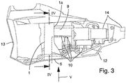
Fig. 3 eine Detailseitenansicht eines Motorgehäuseteils des Gerätes vonFig. 2 bei abgenommener Motorgehäusehälfte, -
Fig. 4 eine Schnittansicht eines z.B. in einem Bearbeitungsgerät nach Art derFig. 1 bis 3 verwendbaren Radialgebläses längs einer Linie IV-IV inFig. 3 und -
Fig. 5 eine Seitenansicht des Radialgebläses längs einer Richtung V inFig. 3 von unten. - Das in den
Fig. 1 bis 3 in beispielhaften Realisierungen gezeigte, handgeführte Bearbeitungsgerät kann insbesondere ein handgeführtes Garten- oder Forstbearbeitungsgerät sein und beinhaltet ein Radialgebläse 1, das, wie aus denFig. 4 und5 genauer zu erkennen, ein Gebläserad 2 und einen Luftkanal 3 aufweist, der einen das Gebläserad 2 umgebenden Spiralabschnitt 3a mit in Luftströmungsrichtung LR zunehmendem Kanalquerschnitt Qk und einen an den Spiralabschnitt 3a anschließenden, sich in Luftströmungsrichtung LR trichterförmig aufweitenden Auslasstrichterabschnitt 3b mit einer radial inneren Begrenzungswand 4a und einer radial äußeren Begrenzungswand 4b umfasst. Der Auslasstrichterabschnitt 3b endet in einer Luftauslassöffnung 6, deren Auslassbreite AB kleiner ist als ein Außendurchmesser Dg des Gebläserades 2. Die radial innere Begrenzungswand 4a und/oder die radial äußere Begrenzungswand 4b des Auslasstrichterabschnitts 3b weist eine zum Spiralabschnitt 3a gegensinnige Krümmung auf. In der Realisierung derFig. 4 und5 weisen beide Begrenzungswände 4a, 4b eine zum Spiralabschnitt 3a gegensinnige Krümmung auf, genauer gesagt der Spiralabschnitt eine Krümmung im Uhrzeigersinn und die beiden Begrenzungswände 4a, 4b des Auslasstrichterabschnitts 3b eine Krümmung im Gegenuhrzeigersinn. Der Luftkanal 3 kann insbesondere durch entsprechende Gestaltung eines Gebläsegehäuses 1a in dessen Innerem gebildet sein, wobei das Gebläserad 2 drehbeweglich in das Gebläsegehäuse 1a eingesetzt ist und das Gebläsegehäuse 1a beispielsweise aus zwei miteinander verbundenen Gehäusehalbschalen aufgebaut sein kann, wie in der gezeigten Ausführung. - Im Auslasstrichterabschnitt 3b ist zwischen der radial inneren Begrenzungswand 4a und der radial äußeren Begrenzungswand 4b eine Zwischenwand 5 angeordnet, die mit zum Spiralabschnitt 3a gegensinniger Krümmung verläuft, d.h. in
Fig. 4 mit einer Krümmung im Gegenuhrzeigersinn, und den Auslasstrichterabschnitt 3b in zwei sich jeweils in Luftströmungsrichtung LR trichterförmig aufweitende Teilabschnitte 8a, 8b aufteilt. - In entsprechenden Ausführungen beinhaltet das Bearbeitungsgerät wie in den Beispielen der
Fig. 1 bis 3 ein Bearbeitungswerkzeug 11, einen elektrischen Antriebsmotor 9 für das Bearbeitungswerkzeug 11 und/oder das Radialgebläse 1 und eine Kühlluftführung 10 für den Antriebsmotor 9, wobei das Radialgebläse 1 in der Kühlluftführung 10 angeordnet ist. In alternativen Ausführungen beinhaltet das Bearbeitungsgerät einen Verbrennungsmotor als Antriebsmotor anstelle des elektrischen Antriebsmotors 9. - In der gezeigten Realisierung der
Fig. 1 bis 3 befindet sich der Antriebsmotor 9 in einem Motorgehäuse 13, in der sich die Kühlluftführung 10 von einem Lufteinlass 12 in das Gehäuse 13 bis zur Luftauslassöffnung 6 aus dem Radialgebläse 1 bzw. aus dem Motorgehäuse 13 erstreckt. Der Antriebsmotor 9 und optional weitere zu kühlende Gerätekomponenten befinden sich in der Kühlluftführung 10, und das Radialgebläse 1 sorgt für den nötigen Kühlluftstrom, wobei es vorzugsweise vom Antriebsmotor 9, alternativ von einem anderen Antrieb, angetrieben wird. In der gezeigten Realisierung ist das Bearbeitungsgerät vom sogenannten Schafttyp, bei dem das Bearbeitungswerkzeug 11 über einen Geräteschaft 14 mit dem Motorgehäuse 13 verbunden ist und durch den Schaft 14 hindurch eine Antriebswelle vom Antriebsmotor 9 zum Bearbeitungswerkzeug 11 führt. In alternativen Realisierungen ist das Bearbeitungsgerät von einem schaftlosen Typ, bei dem z.B. das Bearbeitungswerkzeug 11 im Motorgehäuse 13 oder direkt an dieses anschließend positioniert ist. - In vorteilhaften Ausführungen sind wie im gezeigten Ausführungsbeispiel ein innerer Querabstand QA1 der Zwischenwand 5 von der radial inneren Begrenzungswand 4a und ein äußerer Querabstand QA2 der Zwischenwand 5 von der radial äußeren Begrenzungswand 4b gleich groß oder unterscheiden sich um höchstens 10%, in bevorzugten Realisierungen um höchstens 5%. Dabei versteht es sich, dass die beiden Querabstände QA1, QA2 jeweils auf einen gleichen Punkt der Zwischenwand 5 entlang ihrer Längserstreckung bezogen sind, in
Fig. 4 bespielhaft für einen Punkt Pz angegeben, da sich beide Querabstände QA1, QA2 aufgrund der trichterförmigen Aufweitung beider Teilabschnitte 8a, 8b in Luftströmungsrichtung vergrößern. Alternativ oder zusätzlich sind eine innere Querschnittsfläche QF1 zwischen der Zwischenwand 5 und der radial inneren Begrenzungswand 4a und eine äußere Querschnittsfläche QF2 zwischen der Zwischenwand 5 und der radial äußeren Begrenzungswand 4b gleich groß oder unterscheiden sich um höchstens 10%, insbesondere höchstens 5%, auch hier wieder bezogen auf einen gleichen Punkt der Zwischenwand 5 entlang ihrer Längserstreckung. - Dies bedeutet jeweils, dass der Auslasstrichterabschnitt 3b durch die Zwischenwand 5 in die beiden strömungstechnisch parallelen Teilabschnitte 8a, 8b mit im Wesentlichen gleichem oder jedenfalls nicht stark voneinander verschiedenem Durchströmungsquerschnitt geteilt ist, wobei die beiden Teilabschnitte 8a, 8b in ihrem Verlauf in Luftströmungsrichtung LR diesen im Wesentlichen gleichen bzw. nicht stark unterschiedlichen Durchströmungsquerschnitt gegenseitig beibehalten, während sich der Durchströmungsquerschnitt jedes der beiden Teilabschnitte 8a, 8b für sich genommen in Luftströmungsrichtung LR aufgrund der trichterförmigen Aufweitung kontinuierlich, vorzugsweise stetig, erhöht. Für bestimmte Anwendungen kann alternativ vorgesehen sein, die Zwischenwand 5 merklich zu einer der beiden radialen Begrenzungswände 4a, 4b des Auslasstrichterabschnitts 3b hin versetzt anzuordnen.
- In vorteilhaften Ausführungen ist wie beim gezeigten Ausführungsbeispiel die Wanddicke Wd der Zwischenwand 5 quer zur Luftströmungsrichtung LR konstant. Alternativ ist die Wanddicke Wd zwar nicht konstant, schwankt jedoch um höchstens 10%. Für manche Anwendungen kann es weiter alternativ gewünscht sein, wenn sich die Wanddicke in größerem Maß entlang der Längserstreckung der Zwischenwand 5 ändert, z.B. keilförmig mit einer größten Wanddicke am Keilfuß, die dann typisch um ein Mehrfaches größer ist als die kleinste Wanddicke an der Keilspitze.
- In vorteilhaften Ausführungen schließt die Zwischenwand 5 in Luftströmungsrichtung LR bündig mit der Luftauslassöffnung 6 ab oder endet vor dieser mit einem Abstand Aw, der zwar größer als null ist, jedoch höchstens 10% der Länge WL der Zwischenwand 5 in Luftströmungsrichtung LR und/oder höchstens das Doppelte der Wanddicke Wd der Zwischenwand 5 beträgt, wie beim gezeigten Ausführungsbeispiel. In alternativen Ausführungen endet die Zwischenwand 5 mit einem größeren Abstand Aw vor der Luftauslassöffnung 6.
- In einer vorteilhaften Realisierung beträgt die Wanddicke Wd der Zwischenwand 5 wie beim gezeigten Ausführungsbeispiel höchstens 5% der Auslassbreite AB der Luftauslassöffnung 4. Für manche Anwendungen kann es alternativ gewünscht sein, eine demgegenüber größere Wanddicke Wd der Zwischenwand 5 zu wählen.
- In vorteilhaften Ausführungen erstreckt sich die Zwischenwand 5 mit einer anströmseitigen Wandseitenkante 5a bis in einen Übergangsbereich 7 des Spiralabschnitts 3a und des Auslasstrichterabschnitts 3b. Es zeigt sich, dass diese relativ weit in Richtung des Spiralabschnitts 3a in den Luftkanal 3 hineinragende Erstreckung der Zwischenwand 5 für die gewünschte Geräuschminimierung sehr vorteilhaft ist.
- In entsprechenden Realisierungen setzt sich die radial innere und/oder die radial äußere Begrenzungswand 4a, 4b des Auslasstrichterabschnitts 3b entgegen der Luftströmungsrichtung LR in den Spiralabschnitt 3a hinein fort und wechselt im Übergangsbereich 7 ihren Krümmungssinn. Im gezeigten Beispiel erstreckt sich die radial innere Begrenzungswand 4a bis zu einer anströmseitigen Endkante 15 in den Spiralabschnitt 3a hinein und wechselt an einem zugehörigen Wendepunkt W1 im Übergangsbereich 7 ihren Krümmungssinn. Die radial äußere Begrenzungswand 4b setzt sich in den gesamten Spiralabschnitt 3a hinein um das Gebläserad 2 herum fort und vereinigt sich an einem Vereinigungspunkt VP mit der radial inneren Begrenzungswand 4a. Außerdem wechselt die äußere Begrenzungswand 4b ihren Krümmungssinn an einem Wendepunkt W2 im Übergangsbereich 7. Für manche Anwendungen kann eine alternative Realisierung wünschenswert sein, bei der die radialen Begrenzungswände 4a, 4b ihren Krümmungssinn nicht im Übergangsbereich 7 wechseln bzw. sich nicht in den Spiralabschnitt 3a hinein fortsetzen, insbesondere die radial innere Begrenzungswand 4a.
- In entsprechenden Ausführungen ist die Zwischenwand 5 wie beim gezeigten Ausführungsbespiel perforationsfrei geschlossen ausgebildet, d.h. die Zwischenwand 5 weist keine Öffnungen zwischen den beiden Teilabschnitten 8a, 8b auf, in die sie den Auslasstrichterabschnitt 3b teilt. Für manche Anwendungen kann eine alternative Gestaltung erwünscht sein, bei der die Zwischenwand 5 als perforierte Wand mit einer oder mehreren Perforationsöffnungen gebildet ist.
- In vorteilhaften Realisierungen besitzt die Zwischenwand 5 wie beim gezeigten Beispiel eine schalldämmende Oberfläche 5b und/oder ist aus einem schallabsorbierenden Material gebildet. Geeignete Oberflächenbeschichtungen bzw. Oberflächenprofilierungen und geeignete Wandmaterialien zur Bereitstellung dieser Schalldämmcharakteristik sind für solche Anwendungszwecke an sich bekannt, was daher hier keiner näheren Erläuterungen bedarf. Bei alternativen Ausführungen kann die Zwischenwand 5 ohne schalldämmende Oberfläche aus einem nicht-schallabsorbierenden Material gebildet sein.
- Wie die gezeigten und die weiteren oben erläuterten Ausführungsbeispiele deutlich machen, stellt die Erfindung ein handgeführtes Bearbeitungsgerät zur Verfügung, das in sehr vorteilhafter Weise hinsichtlich geringer Geräuschemission seines Radialgebläses optimiert ist. Das Bearbeitungsgerät kann insbesondere ein handgeführtes Garten- oder Forstbearbeitungsgerät eines beliebigen, herkömmlichen Typs sein, soweit in diesem ein Radialgebläse verwendet wird.
Claims (11)
- Handgeführtes Bearbeitungsgerät, insbesondere handgeführtes Garten- oder Forstbearbeitungsgerät, mit- einem Radialgebläse (1), das ein Gebläserad (2) und einen Luftkanal (3) beinhaltet, der einen das Gebläserad (2) umgebenden Spiralabschnitt (3a) mit in Luftströmungsrichtung (LR) zunehmendem Kanalquerschnitt (Qk) und einen an den Spiralabschnitt (3a) anschließenden, sich in Luftströmungsrichtung (LR) trichterförmig aufweitenden Auslasstrichterabschnitt (3b) mit einer radial inneren Begrenzungswand (4a) und einer radial äußeren Begrenzungswand (4b) umfasst, wobei der Auslasstrichterabschnitt (3b) in einer Luftauslassöffnung (6) endet, deren Auslassbreite (AB) kleiner ist als ein Außendurchmesser (Dg) des Gebläserades (2),- wobei die radial innere und/oder die radial äußere Begrenzungswand (4a, 4b) des Auslasstrichterabschnitts (3b) eine zum Spiralabschnitt (3a) gegensinnige Krümmung aufweist und- wobei im Auslasstrichterabschnitt (3b) eine Zwischenwand (5) zwischen der radial inneren und der radial äußeren Begrenzungswand (4a, 4b) angeordnet ist, wobei die Zwischenwand (5) mit zum Spiralabschnitt (3a) gegensinniger Krümmung verläuft und den Auslasstrichterabschnitt (3b) in zwei sich jeweils in Luftströmungsrichtung (LR) trichterförmig aufweitende Teilabschnitte (8a, 8b) aufteilt.
- Handgeführtes Bearbeitungsgerät nach Anspruch 1, wobei ein innerer Querabstand (QA1) der Zwischenwand (5) von der radial inneren Begrenzungswand (4a) und ein äußerer Querabstand (QA2) der Zwischenwand (5) von der radial äußeren Begrenzungswand (4b) gleich groß sind oder sich um höchstens 10%, insbesondere höchstens 5%, unterscheiden.
- Handgeführtes Bearbeitungsgerät nach Anspruch 1 oder 2, wobei eine innere Querschnittsfläche (QF1) zwischen der Zwischenwand (5) und der radial inneren Begrenzungswand (4a) und eine äußere Querschnittsfläche (QF2) zwischen der Zwischenwand (5) und der radial äußeren Begrenzungswand (4b) gleich groß sind oder sich um höchstens 10%, insbesondere höchstens 5%, unterscheiden.
- Handgeführtes Bearbeitungsgerät nach einem der Ansprüche 1 bis 3, wobei die Wanddicke (Wd) der Zwischenwand (5) quer zur Luftströmungsrichtung (LR) konstant ist oder eine größte Wanddicke um höchstens 10% größer als eine kleinste Wanddicke ist.
- Handgeführtes Bearbeitungsgerät nach einem der Ansprüche 1 bis 4, wobei die Zwischenwand (5) in Luftströmungsrichtung (LR) bündig mit der Luftauslassöffnung (6) abschließt oder mit einem Abstand (Aw) vor dieser endet, der höchstens 10% ihrer Länge (WL) in Luftströmungsrichtung (LR) und/oder höchstens das Doppelte ihrer Wanddicke (Wd) beträgt.
- Handgeführtes Bearbeitungsgerät nach einem der Ansprüche 1 bis 5, wobei die Wanddicke (Wd) der Zwischenwand (5) höchstens 5% der Auslassbreite (AB) der Luftauslassöffnung (4) beträgt.
- Handgeführtes Bearbeitungsgerät nach einem der Ansprüche 1 bis 6, wobei sich die Zwischenwand (5) mit einer anströmseitigen Wandseitenkante (5a) bis in einen Übergangsbereich (7) des Spiralabschnitts (3a) und des Auslasstrichterabschnitts (3b) erstreckt.
- Handgeführtes Bearbeitungsgerät nach einem der Ansprüche 1 bis 7, wobei sich die radial innere und/oder die radial äußere Begrenzungswand (4a, 4b) des Auslasstrichterabschnitts (3b) entgegen der Luftströmungsrichtung (LR) in den Spiralabschnitt (3a) hinein fortsetzt und ihren Krümmungssinn in einem Übergangsbereich (7) des Spiralabschnitts (3a) und des Auslasstrichterabschnitts (3b) wechselt.
- Handgeführtes Bearbeitungsgerät nach einem der Ansprüche 1 bis 8, wobei die Zwischenwand (5) perforationsfrei geschlossen ausgebildet ist.
- Handgeführtes Bearbeitungsgerät nach einem der Ansprüche 1 bis 9, wobei mindestens eine von der Zwischenwand (5), der radial inneren Begrenzungswand (4a) und der radial äußeren Begrenzungswand (4b) eine schalldämmende Oberfläche besitzt und/oder aus einem schallabsorbierenden Material gebildet ist.
- Handgeführtes Bearbeitungsgerät nach einem der Ansprüche 1 bis 10, wobei es ein Bearbeitungswerkzeug (11), einen elektrischen Antriebsmotor (9) für das Bearbeitungswerkzeug (11) und eine Kühlluftführung (10) für den Antriebsmotor (9) aufweist, wobei das Radialgebläse (1) in der Kühlluftführung (10) angeordnet ist.
Priority Applications (3)
| Application Number | Priority Date | Filing Date | Title |
|---|---|---|---|
| EP19205812.1A EP3815520B1 (de) | 2019-10-29 | 2019-10-29 | Handgeführtes bearbeitungsgerät mit radialgebläse |
| US17/082,724 US11434926B2 (en) | 2019-10-29 | 2020-10-28 | Hand-guided working apparatus having a radial fan |
| CN202011183702.XA CN112740860B (zh) | 2019-10-29 | 2020-10-29 | 带有径向鼓风机的手持式加工设备 |
Applications Claiming Priority (1)
| Application Number | Priority Date | Filing Date | Title |
|---|---|---|---|
| EP19205812.1A EP3815520B1 (de) | 2019-10-29 | 2019-10-29 | Handgeführtes bearbeitungsgerät mit radialgebläse |
Publications (2)
| Publication Number | Publication Date |
|---|---|
| EP3815520A1 true EP3815520A1 (de) | 2021-05-05 |
| EP3815520B1 EP3815520B1 (de) | 2022-07-06 |
Family
ID=68387209
Family Applications (1)
| Application Number | Title | Priority Date | Filing Date |
|---|---|---|---|
| EP19205812.1A Active EP3815520B1 (de) | 2019-10-29 | 2019-10-29 | Handgeführtes bearbeitungsgerät mit radialgebläse |
Country Status (3)
| Country | Link |
|---|---|
| US (1) | US11434926B2 (de) |
| EP (1) | EP3815520B1 (de) |
| CN (1) | CN112740860B (de) |
Citations (6)
| Publication number | Priority date | Publication date | Assignee | Title |
|---|---|---|---|---|
| US4232994A (en) * | 1977-01-14 | 1980-11-11 | Hitachi, Ltd. | Centrifugal turbomachine |
| WO1990009524A1 (en) * | 1989-02-14 | 1990-08-23 | Airflow Research & Manufacturing Corporation | Centrifugal fan and diffuser with accumulating volute |
| DE10245418A1 (de) | 2002-09-28 | 2004-06-03 | Andreas Stihl Ag & Co. | Gebläseanordnung |
| DE102005003275A1 (de) | 2005-01-25 | 2006-07-27 | Andreas Stihl Ag & Co. Kg | Rückentragbares Saug-/Blasgerät |
| US20110200426A1 (en) * | 2010-02-15 | 2011-08-18 | Makita Corporation | Noise reduction devices for blowers |
| GB2524315A (en) * | 2014-03-20 | 2015-09-23 | Johnston Sweepers Ltd | Centrifugal fan assembly for road sweeping machines |
Family Cites Families (13)
| Publication number | Priority date | Publication date | Assignee | Title |
|---|---|---|---|---|
| US1529815A (en) * | 1923-10-06 | 1925-03-17 | Siemen Otto | Rotary pump |
| US2001522A (en) * | 1932-05-03 | 1935-05-14 | Chester Thomas | Centrifugal blower |
| IT216542Z2 (it) * | 1989-04-28 | 1991-09-16 | Elite Srl | Asciugacapelli perfezionato con soffiante a chiocciola. |
| US4944654A (en) * | 1989-05-15 | 1990-07-31 | Carrier Corporation | Split scroll for centrifugal blower |
| JP2001153096A (ja) * | 1999-11-30 | 2001-06-05 | Maruyama Mfg Co Ltd | 遠心送風機及び携帯式送風装置 |
| JP3838200B2 (ja) * | 2003-01-09 | 2006-10-25 | 株式会社デンソー | 遠心式送風装置 |
| US20060078423A1 (en) * | 2004-10-08 | 2006-04-13 | Nonlinear Tech, Inc. | Bi-directional Blowers for Cooling Laptop Computers |
| ITVI20070158A1 (it) * | 2007-05-31 | 2008-12-01 | Co Me Fri S P A | Unita' per il trattamento dell'aria a flusso controllato |
| US8231331B2 (en) * | 2008-03-14 | 2012-07-31 | Wayne State University | Reduction of flow-induced noise in a centrifugal blower |
| CN201861590U (zh) * | 2010-12-02 | 2011-06-15 | 佛山市耐堡电气有限公司 | 一种可移动式干地机 |
| US10570928B2 (en) * | 2013-03-15 | 2020-02-25 | Regal Beloit America, Inc. | Centrifugal blower assembly and method for assembling the same |
| AU2018439003B2 (en) * | 2018-08-31 | 2022-07-14 | Mitsubishi Electric Corporation | Centrifugal air-sending device, air-sending apparatus, air-conditioning apparatus, and refrigeration cycle apparatus |
| CN113195902B (zh) * | 2018-12-19 | 2024-04-16 | 三菱电机株式会社 | 离心式鼓风机、鼓风装置、空调装置以及冷冻循环装置 |
-
2019
- 2019-10-29 EP EP19205812.1A patent/EP3815520B1/de active Active
-
2020
- 2020-10-28 US US17/082,724 patent/US11434926B2/en active Active
- 2020-10-29 CN CN202011183702.XA patent/CN112740860B/zh active Active
Patent Citations (6)
| Publication number | Priority date | Publication date | Assignee | Title |
|---|---|---|---|---|
| US4232994A (en) * | 1977-01-14 | 1980-11-11 | Hitachi, Ltd. | Centrifugal turbomachine |
| WO1990009524A1 (en) * | 1989-02-14 | 1990-08-23 | Airflow Research & Manufacturing Corporation | Centrifugal fan and diffuser with accumulating volute |
| DE10245418A1 (de) | 2002-09-28 | 2004-06-03 | Andreas Stihl Ag & Co. | Gebläseanordnung |
| DE102005003275A1 (de) | 2005-01-25 | 2006-07-27 | Andreas Stihl Ag & Co. Kg | Rückentragbares Saug-/Blasgerät |
| US20110200426A1 (en) * | 2010-02-15 | 2011-08-18 | Makita Corporation | Noise reduction devices for blowers |
| GB2524315A (en) * | 2014-03-20 | 2015-09-23 | Johnston Sweepers Ltd | Centrifugal fan assembly for road sweeping machines |
Also Published As
| Publication number | Publication date |
|---|---|
| US20210123457A1 (en) | 2021-04-29 |
| CN112740860B (zh) | 2024-09-17 |
| EP3815520B1 (de) | 2022-07-06 |
| CN112740860A (zh) | 2021-05-04 |
| US11434926B2 (en) | 2022-09-06 |
Similar Documents
| Publication | Publication Date | Title |
|---|---|---|
| DE60019264T2 (de) | Abgasmischvorrichtung und gerät mit einer solchen vorrichtung | |
| DE2404001C2 (de) | Schallunterdrückungsverkleidung für Strömungskanäle von Gasturbinentriebwerken | |
| DE60210000T2 (de) | Antirausch- und Antiwirbelstabilisator | |
| CH669431A5 (de) | ||
| DE2242219A1 (de) | Geraeuscharmer antriebsventilator | |
| DE102007037924A1 (de) | Strömungsarbeitsmaschine mit Ringkanalwandausnehmung | |
| DE4423762A1 (de) | Gebläseapparat | |
| DE19903165A1 (de) | Ansaugvorrichtung mit einem Durchbrüche aufweisenden Leitungsabschnitt | |
| DE102009032207B4 (de) | Ventilator | |
| WO2020015800A1 (de) | Gehäuse für einen ventilator und ventilator | |
| DE102013225642A1 (de) | Abgasturbolader | |
| DE102024110701A1 (de) | Beatmungsgerät | |
| EP1510667A2 (de) | Schalldämpfer | |
| EP3372838A1 (de) | Luftleitanordnung | |
| EP0332078B1 (de) | Ringkanalgebläse | |
| DE112020004602T5 (de) | Turbinenflügel | |
| EP0896759B1 (de) | Schnellaufender elektromotor | |
| EP2633220A2 (de) | Scheibendämpfer für ladeluftleitungen eines verbrennungsmotors mit turbolader | |
| EP3815520B1 (de) | Handgeführtes bearbeitungsgerät mit radialgebläse | |
| EP3099983B1 (de) | Wärmepumpe | |
| DE2422145A1 (de) | Pneumatisch angetriebene, tragbare werkzeugmaschine | |
| DE3152556T1 (de) | Strömungsfreier axialer Durchfluß- oder Strömungsventilator | |
| DE20309621U1 (de) | Radialgebläse | |
| DE102019220089A1 (de) | Düsenelement für einen Strahlventilator und Strahlventilator | |
| DE102019115011A1 (de) | Verdichter mit Einlasseinsatz und Rückführungskanal |
Legal Events
| Date | Code | Title | Description |
|---|---|---|---|
| PUAI | Public reference made under article 153(3) epc to a published international application that has entered the european phase |
Free format text: ORIGINAL CODE: 0009012 |
|
| STAA | Information on the status of an ep patent application or granted ep patent |
Free format text: STATUS: THE APPLICATION HAS BEEN PUBLISHED |
|
| AK | Designated contracting states |
Kind code of ref document: A1 Designated state(s): AL AT BE BG CH CY CZ DE DK EE ES FI FR GB GR HR HU IE IS IT LI LT LU LV MC MK MT NL NO PL PT RO RS SE SI SK SM TR |
|
| STAA | Information on the status of an ep patent application or granted ep patent |
Free format text: STATUS: REQUEST FOR EXAMINATION WAS MADE |
|
| 17P | Request for examination filed |
Effective date: 20210901 |
|
| RBV | Designated contracting states (corrected) |
Designated state(s): AL AT BE BG CH CY CZ DE DK EE ES FI FR GB GR HR HU IE IS IT LI LT LU LV MC MK MT NL NO PL PT RO RS SE SI SK SM TR |
|
| GRAP | Despatch of communication of intention to grant a patent |
Free format text: ORIGINAL CODE: EPIDOSNIGR1 |
|
| STAA | Information on the status of an ep patent application or granted ep patent |
Free format text: STATUS: GRANT OF PATENT IS INTENDED |
|
| INTG | Intention to grant announced |
Effective date: 20220214 |
|
| GRAS | Grant fee paid |
Free format text: ORIGINAL CODE: EPIDOSNIGR3 |
|
| GRAA | (expected) grant |
Free format text: ORIGINAL CODE: 0009210 |
|
| STAA | Information on the status of an ep patent application or granted ep patent |
Free format text: STATUS: THE PATENT HAS BEEN GRANTED |
|
| AK | Designated contracting states |
Kind code of ref document: B1 Designated state(s): AL AT BE BG CH CY CZ DE DK EE ES FI FR GB GR HR HU IE IS IT LI LT LU LV MC MK MT NL NO PL PT RO RS SE SI SK SM TR |
|
| REG | Reference to a national code |
Ref country code: AT Ref legal event code: REF Ref document number: 1502179 Country of ref document: AT Kind code of ref document: T Effective date: 20220715 Ref country code: CH Ref legal event code: EP |
|
| REG | Reference to a national code |
Ref country code: DE Ref legal event code: R096 Ref document number: 502019004867 Country of ref document: DE |
|
| REG | Reference to a national code |
Ref country code: IE Ref legal event code: FG4D Free format text: LANGUAGE OF EP DOCUMENT: GERMAN |
|
| REG | Reference to a national code |
Ref country code: LT Ref legal event code: MG9D |
|
| REG | Reference to a national code |
Ref country code: NL Ref legal event code: MP Effective date: 20220706 |
|
| PG25 | Lapsed in a contracting state [announced via postgrant information from national office to epo] |
Ref country code: SE Free format text: LAPSE BECAUSE OF FAILURE TO SUBMIT A TRANSLATION OF THE DESCRIPTION OR TO PAY THE FEE WITHIN THE PRESCRIBED TIME-LIMIT Effective date: 20220706 Ref country code: RS Free format text: LAPSE BECAUSE OF FAILURE TO SUBMIT A TRANSLATION OF THE DESCRIPTION OR TO PAY THE FEE WITHIN THE PRESCRIBED TIME-LIMIT Effective date: 20220706 Ref country code: PT Free format text: LAPSE BECAUSE OF FAILURE TO SUBMIT A TRANSLATION OF THE DESCRIPTION OR TO PAY THE FEE WITHIN THE PRESCRIBED TIME-LIMIT Effective date: 20221107 Ref country code: NO Free format text: LAPSE BECAUSE OF FAILURE TO SUBMIT A TRANSLATION OF THE DESCRIPTION OR TO PAY THE FEE WITHIN THE PRESCRIBED TIME-LIMIT Effective date: 20221006 Ref country code: NL Free format text: LAPSE BECAUSE OF FAILURE TO SUBMIT A TRANSLATION OF THE DESCRIPTION OR TO PAY THE FEE WITHIN THE PRESCRIBED TIME-LIMIT Effective date: 20220706 Ref country code: LV Free format text: LAPSE BECAUSE OF FAILURE TO SUBMIT A TRANSLATION OF THE DESCRIPTION OR TO PAY THE FEE WITHIN THE PRESCRIBED TIME-LIMIT Effective date: 20220706 Ref country code: LT Free format text: LAPSE BECAUSE OF FAILURE TO SUBMIT A TRANSLATION OF THE DESCRIPTION OR TO PAY THE FEE WITHIN THE PRESCRIBED TIME-LIMIT Effective date: 20220706 Ref country code: FI Free format text: LAPSE BECAUSE OF FAILURE TO SUBMIT A TRANSLATION OF THE DESCRIPTION OR TO PAY THE FEE WITHIN THE PRESCRIBED TIME-LIMIT Effective date: 20220706 Ref country code: ES Free format text: LAPSE BECAUSE OF FAILURE TO SUBMIT A TRANSLATION OF THE DESCRIPTION OR TO PAY THE FEE WITHIN THE PRESCRIBED TIME-LIMIT Effective date: 20220706 |
|
| PG25 | Lapsed in a contracting state [announced via postgrant information from national office to epo] |
Ref country code: PL Free format text: LAPSE BECAUSE OF FAILURE TO SUBMIT A TRANSLATION OF THE DESCRIPTION OR TO PAY THE FEE WITHIN THE PRESCRIBED TIME-LIMIT Effective date: 20220706 Ref country code: IS Free format text: LAPSE BECAUSE OF FAILURE TO SUBMIT A TRANSLATION OF THE DESCRIPTION OR TO PAY THE FEE WITHIN THE PRESCRIBED TIME-LIMIT Effective date: 20221106 Ref country code: HR Free format text: LAPSE BECAUSE OF FAILURE TO SUBMIT A TRANSLATION OF THE DESCRIPTION OR TO PAY THE FEE WITHIN THE PRESCRIBED TIME-LIMIT Effective date: 20220706 Ref country code: GR Free format text: LAPSE BECAUSE OF FAILURE TO SUBMIT A TRANSLATION OF THE DESCRIPTION OR TO PAY THE FEE WITHIN THE PRESCRIBED TIME-LIMIT Effective date: 20221007 |
|
| REG | Reference to a national code |
Ref country code: DE Ref legal event code: R097 Ref document number: 502019004867 Country of ref document: DE |
|
| PG25 | Lapsed in a contracting state [announced via postgrant information from national office to epo] |
Ref country code: SM Free format text: LAPSE BECAUSE OF FAILURE TO SUBMIT A TRANSLATION OF THE DESCRIPTION OR TO PAY THE FEE WITHIN THE PRESCRIBED TIME-LIMIT Effective date: 20220706 Ref country code: RO Free format text: LAPSE BECAUSE OF FAILURE TO SUBMIT A TRANSLATION OF THE DESCRIPTION OR TO PAY THE FEE WITHIN THE PRESCRIBED TIME-LIMIT Effective date: 20220706 Ref country code: DK Free format text: LAPSE BECAUSE OF FAILURE TO SUBMIT A TRANSLATION OF THE DESCRIPTION OR TO PAY THE FEE WITHIN THE PRESCRIBED TIME-LIMIT Effective date: 20220706 Ref country code: CZ Free format text: LAPSE BECAUSE OF FAILURE TO SUBMIT A TRANSLATION OF THE DESCRIPTION OR TO PAY THE FEE WITHIN THE PRESCRIBED TIME-LIMIT Effective date: 20220706 |
|
| PLBE | No opposition filed within time limit |
Free format text: ORIGINAL CODE: 0009261 |
|
| STAA | Information on the status of an ep patent application or granted ep patent |
Free format text: STATUS: NO OPPOSITION FILED WITHIN TIME LIMIT |
|
| PG25 | Lapsed in a contracting state [announced via postgrant information from national office to epo] |
Ref country code: SK Free format text: LAPSE BECAUSE OF FAILURE TO SUBMIT A TRANSLATION OF THE DESCRIPTION OR TO PAY THE FEE WITHIN THE PRESCRIBED TIME-LIMIT Effective date: 20220706 Ref country code: MC Free format text: LAPSE BECAUSE OF FAILURE TO SUBMIT A TRANSLATION OF THE DESCRIPTION OR TO PAY THE FEE WITHIN THE PRESCRIBED TIME-LIMIT Effective date: 20220706 Ref country code: EE Free format text: LAPSE BECAUSE OF FAILURE TO SUBMIT A TRANSLATION OF THE DESCRIPTION OR TO PAY THE FEE WITHIN THE PRESCRIBED TIME-LIMIT Effective date: 20220706 |
|
| REG | Reference to a national code |
Ref country code: CH Ref legal event code: PL |
|
| 26N | No opposition filed |
Effective date: 20230411 |
|
| REG | Reference to a national code |
Ref country code: BE Ref legal event code: MM Effective date: 20221031 |
|
| PG25 | Lapsed in a contracting state [announced via postgrant information from national office to epo] |
Ref country code: LU Free format text: LAPSE BECAUSE OF NON-PAYMENT OF DUE FEES Effective date: 20221029 Ref country code: AL Free format text: LAPSE BECAUSE OF FAILURE TO SUBMIT A TRANSLATION OF THE DESCRIPTION OR TO PAY THE FEE WITHIN THE PRESCRIBED TIME-LIMIT Effective date: 20220706 |
|
| PG25 | Lapsed in a contracting state [announced via postgrant information from national office to epo] |
Ref country code: LI Free format text: LAPSE BECAUSE OF NON-PAYMENT OF DUE FEES Effective date: 20221031 Ref country code: CH Free format text: LAPSE BECAUSE OF NON-PAYMENT OF DUE FEES Effective date: 20221031 |
|
| PG25 | Lapsed in a contracting state [announced via postgrant information from national office to epo] |
Ref country code: SI Free format text: LAPSE BECAUSE OF FAILURE TO SUBMIT A TRANSLATION OF THE DESCRIPTION OR TO PAY THE FEE WITHIN THE PRESCRIBED TIME-LIMIT Effective date: 20220706 |
|
| PG25 | Lapsed in a contracting state [announced via postgrant information from national office to epo] |
Ref country code: BE Free format text: LAPSE BECAUSE OF NON-PAYMENT OF DUE FEES Effective date: 20221031 |
|
| PG25 | Lapsed in a contracting state [announced via postgrant information from national office to epo] |
Ref country code: IE Free format text: LAPSE BECAUSE OF NON-PAYMENT OF DUE FEES Effective date: 20221029 |
|
| PG25 | Lapsed in a contracting state [announced via postgrant information from national office to epo] |
Ref country code: IT Free format text: LAPSE BECAUSE OF FAILURE TO SUBMIT A TRANSLATION OF THE DESCRIPTION OR TO PAY THE FEE WITHIN THE PRESCRIBED TIME-LIMIT Effective date: 20220706 |
|
| PGFP | Annual fee paid to national office [announced via postgrant information from national office to epo] |
Ref country code: FR Payment date: 20231026 Year of fee payment: 5 |
|
| PG25 | Lapsed in a contracting state [announced via postgrant information from national office to epo] |
Ref country code: CY Free format text: LAPSE BECAUSE OF FAILURE TO SUBMIT A TRANSLATION OF THE DESCRIPTION OR TO PAY THE FEE WITHIN THE PRESCRIBED TIME-LIMIT Effective date: 20220706 |
|
| PG25 | Lapsed in a contracting state [announced via postgrant information from national office to epo] |
Ref country code: MK Free format text: LAPSE BECAUSE OF FAILURE TO SUBMIT A TRANSLATION OF THE DESCRIPTION OR TO PAY THE FEE WITHIN THE PRESCRIBED TIME-LIMIT Effective date: 20220706 Ref country code: HU Free format text: LAPSE BECAUSE OF FAILURE TO SUBMIT A TRANSLATION OF THE DESCRIPTION OR TO PAY THE FEE WITHIN THE PRESCRIBED TIME-LIMIT; INVALID AB INITIO Effective date: 20191029 |
|
| GBPC | Gb: european patent ceased through non-payment of renewal fee |
Effective date: 20231029 |
|
| PG25 | Lapsed in a contracting state [announced via postgrant information from national office to epo] |
Ref country code: TR Free format text: LAPSE BECAUSE OF FAILURE TO SUBMIT A TRANSLATION OF THE DESCRIPTION OR TO PAY THE FEE WITHIN THE PRESCRIBED TIME-LIMIT Effective date: 20220706 |
|
| PG25 | Lapsed in a contracting state [announced via postgrant information from national office to epo] |
Ref country code: GB Free format text: LAPSE BECAUSE OF NON-PAYMENT OF DUE FEES Effective date: 20231029 |
|
| PG25 | Lapsed in a contracting state [announced via postgrant information from national office to epo] |
Ref country code: GB Free format text: LAPSE BECAUSE OF NON-PAYMENT OF DUE FEES Effective date: 20231029 Ref country code: BG Free format text: LAPSE BECAUSE OF FAILURE TO SUBMIT A TRANSLATION OF THE DESCRIPTION OR TO PAY THE FEE WITHIN THE PRESCRIBED TIME-LIMIT Effective date: 20220706 |
|
| PG25 | Lapsed in a contracting state [announced via postgrant information from national office to epo] |
Ref country code: MT Free format text: LAPSE BECAUSE OF FAILURE TO SUBMIT A TRANSLATION OF THE DESCRIPTION OR TO PAY THE FEE WITHIN THE PRESCRIBED TIME-LIMIT Effective date: 20220706 |
|
| PG25 | Lapsed in a contracting state [announced via postgrant information from national office to epo] |
Ref country code: FR Free format text: LAPSE BECAUSE OF NON-PAYMENT OF DUE FEES Effective date: 20241031 |
|
| REG | Reference to a national code |
Ref country code: AT Ref legal event code: MM01 Ref document number: 1502179 Country of ref document: AT Kind code of ref document: T Effective date: 20241029 |
|
| PGFP | Annual fee paid to national office [announced via postgrant information from national office to epo] |
Ref country code: DE Payment date: 20251028 Year of fee payment: 7 |
|
| PG25 | Lapsed in a contracting state [announced via postgrant information from national office to epo] |
Ref country code: AT Free format text: LAPSE BECAUSE OF NON-PAYMENT OF DUE FEES Effective date: 20241029 |
|
| PGFP | Annual fee paid to national office [announced via postgrant information from national office to epo] |
Ref country code: AT Payment date: 20260410 Year of fee payment: 5 |