EP3372838A1 - Luftleitanordnung - Google Patents
Luftleitanordnung Download PDFInfo
- Publication number
- EP3372838A1 EP3372838A1 EP18160318.4A EP18160318A EP3372838A1 EP 3372838 A1 EP3372838 A1 EP 3372838A1 EP 18160318 A EP18160318 A EP 18160318A EP 3372838 A1 EP3372838 A1 EP 3372838A1
- Authority
- EP
- European Patent Office
- Prior art keywords
- air guide
- air
- downstream
- baffle
- baffles
- Prior art date
- Legal status (The legal status is an assumption and is not a legal conclusion. Google has not performed a legal analysis and makes no representation as to the accuracy of the status listed.)
- Granted
Links
- 230000015572 biosynthetic process Effects 0.000 claims abstract description 45
- 238000005755 formation reaction Methods 0.000 claims abstract description 45
- 238000009423 ventilation Methods 0.000 claims abstract description 9
- 239000002184 metal Substances 0.000 claims description 17
- 230000004323 axial length Effects 0.000 claims description 3
- 239000011358 absorbing material Substances 0.000 claims description 2
- 230000000694 effects Effects 0.000 claims description 2
- 238000005452 bending Methods 0.000 description 2
- UJCHIZDEQZMODR-BYPYZUCNSA-N (2r)-2-acetamido-3-sulfanylpropanamide Chemical compound CC(=O)N[C@@H](CS)C(N)=O UJCHIZDEQZMODR-BYPYZUCNSA-N 0.000 description 1
- 241001669680 Dormitator maculatus Species 0.000 description 1
- 238000004378 air conditioning Methods 0.000 description 1
- 230000000712 assembly Effects 0.000 description 1
- 238000000429 assembly Methods 0.000 description 1
- 238000011161 development Methods 0.000 description 1
- 230000018109 developmental process Effects 0.000 description 1
- 230000003068 static effect Effects 0.000 description 1
Images


Classifications
-
- F—MECHANICAL ENGINEERING; LIGHTING; HEATING; WEAPONS; BLASTING
- F04—POSITIVE - DISPLACEMENT MACHINES FOR LIQUIDS; PUMPS FOR LIQUIDS OR ELASTIC FLUIDS
- F04D—NON-POSITIVE-DISPLACEMENT PUMPS
- F04D17/00—Radial-flow pumps, e.g. centrifugal pumps; Helico-centrifugal pumps
- F04D17/08—Centrifugal pumps
- F04D17/16—Centrifugal pumps for displacing without appreciable compression
- F04D17/165—Axial entry and discharge
-
- F—MECHANICAL ENGINEERING; LIGHTING; HEATING; WEAPONS; BLASTING
- F04—POSITIVE - DISPLACEMENT MACHINES FOR LIQUIDS; PUMPS FOR LIQUIDS OR ELASTIC FLUIDS
- F04D—NON-POSITIVE-DISPLACEMENT PUMPS
- F04D29/00—Details, component parts, or accessories
- F04D29/40—Casings; Connections of working fluid
- F04D29/42—Casings; Connections of working fluid for radial or helico-centrifugal pumps
- F04D29/4206—Casings; Connections of working fluid for radial or helico-centrifugal pumps especially adapted for elastic fluid pumps
- F04D29/4226—Fan casings
- F04D29/4253—Fan casings with axial entry and discharge
-
- F—MECHANICAL ENGINEERING; LIGHTING; HEATING; WEAPONS; BLASTING
- F04—POSITIVE - DISPLACEMENT MACHINES FOR LIQUIDS; PUMPS FOR LIQUIDS OR ELASTIC FLUIDS
- F04D—NON-POSITIVE-DISPLACEMENT PUMPS
- F04D29/00—Details, component parts, or accessories
- F04D29/40—Casings; Connections of working fluid
- F04D29/42—Casings; Connections of working fluid for radial or helico-centrifugal pumps
- F04D29/44—Fluid-guiding means, e.g. diffusers
- F04D29/441—Fluid-guiding means, e.g. diffusers especially adapted for elastic fluid pumps
- F04D29/444—Bladed diffusers
-
- F—MECHANICAL ENGINEERING; LIGHTING; HEATING; WEAPONS; BLASTING
- F04—POSITIVE - DISPLACEMENT MACHINES FOR LIQUIDS; PUMPS FOR LIQUIDS OR ELASTIC FLUIDS
- F04D—NON-POSITIVE-DISPLACEMENT PUMPS
- F04D29/00—Details, component parts, or accessories
- F04D29/66—Combating cavitation, whirls, noise, vibration or the like; Balancing
- F04D29/661—Combating cavitation, whirls, noise, vibration or the like; Balancing especially adapted for elastic fluid pumps
- F04D29/666—Combating cavitation, whirls, noise, vibration or the like; Balancing especially adapted for elastic fluid pumps by means of rotor construction or layout, e.g. unequal distribution of blades or vanes
-
- F—MECHANICAL ENGINEERING; LIGHTING; HEATING; WEAPONS; BLASTING
- F04—POSITIVE - DISPLACEMENT MACHINES FOR LIQUIDS; PUMPS FOR LIQUIDS OR ELASTIC FLUIDS
- F04D—NON-POSITIVE-DISPLACEMENT PUMPS
- F04D29/00—Details, component parts, or accessories
- F04D29/66—Combating cavitation, whirls, noise, vibration or the like; Balancing
- F04D29/661—Combating cavitation, whirls, noise, vibration or the like; Balancing especially adapted for elastic fluid pumps
- F04D29/667—Combating cavitation, whirls, noise, vibration or the like; Balancing especially adapted for elastic fluid pumps by influencing the flow pattern, e.g. suppression of turbulence
-
- F—MECHANICAL ENGINEERING; LIGHTING; HEATING; WEAPONS; BLASTING
- F24—HEATING; RANGES; VENTILATING
- F24F—AIR-CONDITIONING; AIR-HUMIDIFICATION; VENTILATION; USE OF AIR CURRENTS FOR SCREENING
- F24F7/00—Ventilation
- F24F7/007—Ventilation with forced flow
-
- F—MECHANICAL ENGINEERING; LIGHTING; HEATING; WEAPONS; BLASTING
- F04—POSITIVE - DISPLACEMENT MACHINES FOR LIQUIDS; PUMPS FOR LIQUIDS OR ELASTIC FLUIDS
- F04D—NON-POSITIVE-DISPLACEMENT PUMPS
- F04D29/00—Details, component parts, or accessories
- F04D29/66—Combating cavitation, whirls, noise, vibration or the like; Balancing
- F04D29/661—Combating cavitation, whirls, noise, vibration or the like; Balancing especially adapted for elastic fluid pumps
- F04D29/663—Sound attenuation
- F04D29/664—Sound attenuation by means of sound absorbing material
-
- F—MECHANICAL ENGINEERING; LIGHTING; HEATING; WEAPONS; BLASTING
- F04—POSITIVE - DISPLACEMENT MACHINES FOR LIQUIDS; PUMPS FOR LIQUIDS OR ELASTIC FLUIDS
- F04D—NON-POSITIVE-DISPLACEMENT PUMPS
- F04D29/00—Details, component parts, or accessories
- F04D29/66—Combating cavitation, whirls, noise, vibration or the like; Balancing
- F04D29/661—Combating cavitation, whirls, noise, vibration or the like; Balancing especially adapted for elastic fluid pumps
- F04D29/663—Sound attenuation
- F04D29/665—Sound attenuation by means of resonance chambers or interference
-
- F—MECHANICAL ENGINEERING; LIGHTING; HEATING; WEAPONS; BLASTING
- F05—INDEXING SCHEMES RELATING TO ENGINES OR PUMPS IN VARIOUS SUBCLASSES OF CLASSES F01-F04
- F05D—INDEXING SCHEME FOR ASPECTS RELATING TO NON-POSITIVE-DISPLACEMENT MACHINES OR ENGINES, GAS-TURBINES OR JET-PROPULSION PLANTS
- F05D2230/00—Manufacture
- F05D2230/50—Building or constructing in particular ways
- F05D2230/54—Building or constructing in particular ways by sheet metal manufacturing
-
- F—MECHANICAL ENGINEERING; LIGHTING; HEATING; WEAPONS; BLASTING
- F05—INDEXING SCHEMES RELATING TO ENGINES OR PUMPS IN VARIOUS SUBCLASSES OF CLASSES F01-F04
- F05D—INDEXING SCHEME FOR ASPECTS RELATING TO NON-POSITIVE-DISPLACEMENT MACHINES OR ENGINES, GAS-TURBINES OR JET-PROPULSION PLANTS
- F05D2250/00—Geometry
- F05D2250/50—Inlet or outlet
- F05D2250/52—Outlet
Definitions
- the invention relates to an air guide arrangement for a centrifugal fan in a ventilation and air conditioning system, preferably for a channel-shaped housing having a rectangular, round or square cross-section.
- Air guide assemblies and air deflection devices are known in the prior art in different designs.
- the simplest embodiments are sheets, with which the flow direction is deflected in an air flow.
- An air deflecting device is, for example, from DE 89 08 987 U known.
- the deflection of the air takes place from the radial to the axial direction exclusively on the housing wall of the conveying channel.
- the air conveyed outwards by the blades occurs in the radial direction on the walls of the delivery channel housing.
- This leads to strong flow losses and to a strong noise.
- it can in this case in the outflow gap between the Abströmblech and the housing wall opposite, close to the dividing area lead to strong turbulence, which not only reinforce the mentioned disadvantages, but above all unfavorable to a flow control by changing the gap between the inlet and inlet of the fan wheel.
- the DE 4129211 A1 is concerned with achieving a gentle deflection of the pumped medium and avoiding turbulence in the region opposite the outflow gap. This is achieved in that the conveying channel is provided with a deflecting funnel which comprises at least the suction-side edge region of the centrifugal fan impeller and has a spacing which extends in the transport direction of the gas as far as the conveying channel cross-section.
- Radial fans are well known and include an impeller driven by a drive motor.
- the impeller generally has on its downstream side a cover plate, to which the impeller blades adjoin.
- the air is usually sucked parallel to the drive axis of the centrifugal fan in a radial fan, thus axially and deflected by the rotation of the impeller by 90 ° and blown out radially.
- the sucked air is thus radially outward, d. H. blown in the direction of the wall of a channel-shaped housing. So that the air on the pressure side of the centrifugal fan, d. H. on the downstream side, flowing again in the main flow direction, the air flow must be redirected again at the wall by 90 °. This creates eddy and an undesirable pressure loss, which reduces the overall efficiency of a centrifugal fan in such an application.
- the invention is therefore based on the object to avoid the aforementioned disadvantages and to provide an arrangement in which the outflow of the transported air or gas quantity of the centrifugal fan is improved, so that as a result the efficiency is increased due to a lower pressure drop.
- the aim is to allow the air flow taken in by a centrifugal fan to flow out into a channel-shaped housing as loss-free as possible.
- a basic idea of the invention is to arrange the radial air flow of the radial fan via one or more baffle formations of specifically arranged and shaped baffles downstream of a radial fan so that the existing twist is reduced by the baffles are used against the spin direction.
- the flow cross-section is widened along the baffle formation, thereby achieving a diffuser effect.
- an air guiding arrangement which is designed for a ventilation system with a channel-shaped housing and a radial fan arranged in a cross-sectional plane in the housing, wherein the air guide arrangement comprises at least one baffle formation of a plurality of differently oriented air baffles, wherein an air passage between the baffles Leitblechformation (s) and the interior of the housing is formed so that the existing swirl is reduced by the baffles are oriented counter to the twisting direction.
- further Leitblechformation is formed as a substantially pyramidal and / or funnel-shaped Leitblechformation with a square or rectangular cross section, which preferably corresponds to the cross section of the channel-shaped housing in which the air guide assembly is intended to be used ,
- this suction-side guide plate formation is formed or formed from four substantially flat, trapezoidal air guide plates which are each connected at an angle ⁇ to a base plate arranged in the cross-sectional plane of the housing and acting as a nozzle with a central opening.
- a pyramidal baffle formation is provided in which the side walls are preferably oriented at an angle ⁇ between 45 ° and 80 ° relative to the cross-sectional plane.
- the guide plate formation arranged downstream, which is to be provided downstream of the radial fan, as a substantially pyramid-shaped or funnel-shaped Leitblechformation is formed with a running in the cross-sectional plane of the housing base with a substantially square or rectangular cross-section.
- downstream baffle formation is formed of four pairs arranged in each case twice folded air baffles, which are folded and arranged to each other, that results in the aforementioned pyramidal or funnel-shaped baffle formation.
- the individual baffles each form a triangular sheet metal section, which in each case forms a partial segment of the base of the downstream baffle formation.
- this triangular plate section is followed by a substantially bent in the axial direction of the centrifugal fan or bevelled rectangular sheet metal section with two side edges, wherein the baffles are preferably arranged rotated by an angle of 0 ° to 20 ° with respect to the axial direction.
- a further Belchabites is formed on the respective baffle as an angled fin and preferably at the triangular sheet metal section.
- the bending angle of the two baffles of a baffle pair of the respective rectangular sheet metal sections with respect to the triangular sheet metal sections is different and with a difference angle ⁇ of about 3 ° to 10 °.
- a difference angle ⁇ of about 3 ° to 10 °.
- the same angle are conceivable.
- downstream baffle formation is formed of four each along an edge angled air baffles, each with a first flat trapezoidal baffle section, which under a defined angle of attack on a formed in the cross-sectional plane arranged base plate are formed.
- the angled air guide plates adjacent to the said edge each form a downstream flat preferably also trapezoidal Leitblechabêt which is oriented at a larger angle than the angle of attack of the aforementioned Porterblechabitess relative to the cross-sectional plane.
- the first and / or second guide plate formation has at least one plurality of preferably rectangular and / or curved air guide vanes, which extend in the radial direction.
- the plurality of air guide vanes can be connected or arranged on the outer surface of the air guide plates of the downstream guide plate formation or on the inner surface of the first guide plate formation.
- the majority of the air guide vanes extends as far as possible to the outside so that they extend to the inner wall of the housing in the installed state of the air guide.
- the majority of the air guide vanes extend as far as possible to the inside so that they extend in the installed state of the air guide arrangement to the outer contour of the radial fan (viewed in the axial direction).
- Another aspect of the present invention relates to an air guide assembly as described above, which is at least partially disposed around a radial fan in a channel-shaped housing of a ventilation system, wherein a Leitblechformation as described above downstream of the centrifugal fan is arranged.
- FIGS. 1 to 12 explained with reference to the description of the various embodiments, wherein like reference numerals indicate structurally and / or functionally identical components.
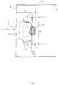
- a sectional view through a channel-shaped housing 30 of a ventilation system ventilation system is shown in which a radial fan 40 is arranged with fan blades 41, which can be rotated by a motor 42 in rotation. Indicated is an air flow whose course is shown schematically with the aid of the illustrated arrows.
- the radial fan sucks air axially via the intake opening A, which is then transferred in the area of the fan blades 41 first into a radial and then downstream again into an axial flow.
- FIG. 6 is a perspective view of an embodiment of an air guide assembly 1 and next to it a sectional view of this air guide assembly 1 in a channel-shaped housing 30 with a centrifugal fan 40 is shown.
- this exemplary embodiment will be described to explain the geometries of the air guide assembly 1 in particular with respect to the radial fan 40 and the housing 30 in more detail.
- the air guide assembly 1 is arranged around the arranged on the cross-sectional plane E radial fan 40 around.
- This air guide assembly 1 shows in addition a suction-side baffle 10 of four each oriented at 90 ° angle offset to each other air baffles 11. These can also from a single accordingly Between the air baffles 11, 21 of the baffle formations 10, 20 and the interior 31 of the housing 30, an air passage 2 is formed, due to the different angles of attack ß1, ß2 of the sections of the air baffles 21, the effective flow cross-section for the conveyed by the radial fan 40 air in the flow direction S increases in this area.
- the baffle 10 represents a substantially funnel or pyramid-shaped baffle 10 with a square cross-section. This is formed of four flat, interconnected trapezoidal baffles 11, each arranged at a same angle ⁇ at one in the cross-sectional plane E, as a nozzle acting provided with a central opening base plate 12 are connected.
- the angle of attack ⁇ of the air baffles 11 is preferably between 45 ° and 80 °.
- the downstream baffle formation 20 is formed from a bent along an edge K (deflected) air baffle 21, which forms four sheet metal segments.
- This guide plate formation 20 represents a substantially funnel-shaped baffle formation with a square cross section.
- Each of the four segments of the baffle 21 has a first flat baffle section 21a, which is connected at an angle ⁇ 1 to the base plate 22 arranged in the cross-sectional plane E.
- Each of the four segments of the Lucasleitbelchs 21 further comprises a downstream (adjacent to the first baffle portion 21a) flat baffle portion 21 b, which is oriented at an angle ⁇ 2 with respect to the cross-sectional plane E.
- the angle of attack ⁇ 1 is preferably between 30 ° and 90 °, while the angle of attack ⁇ 2 is preferably between 90 ° and 100 °.
- the ratio Xa / La of the distance Xa of the edge K of the Lucasleitbelchs 21 to the base 22 to the diameter La of the centrifugal fan is between 0.05 and 0.5. In this embodiment of the invention is due to the canted shape of the downstream Leitblechformation 20 an extension of the Flow cross section causes. This leads to a reduction of the flow velocity and thus to an increase of the static Pressure.
- the axial length of the baffle portion 21 b measured from the edge K to the trailing edge is denoted by Xb.
- a preferred choice for the ratio Xb / La is in the range of 0.15 to 0.8.
- Preferred sizes for Yb / LA are between 1.1 and 2.0.
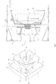
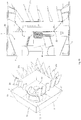
- FIGS. 2 to 5 views of an alternative embodiment of an air guide assembly 1 in a channel shaped housing 30 having a radial fan 40 are shown.
- the two Heilleitformationen 10, 20 are also here essentially funnel or pyramidal.
- the first baffle 10 is, as in the previously described embodiment of the Fig. 6 educated.
- the second guide plate formation 20 is formed from four paired folded-edge air guide plates 21.
- the shape of the individual air baffles 21 is in the FIG. 3 clearly visible.
- the individual baffles 21 each form a triangular sheet-metal section 21d, which in each case forms a partial segment of the base 22 of the downstream baffle formation 20.
- At this triangular sheet metal portion 21d is a substantially to the axial direction of the radial fan 40 bent or folded rectangular sheet metal section 21 e with in each case two side edges 21k, wherein the baffles preferably by an angle ⁇ of 0 ° to 20 ° with respect to the axial direction are arranged twisted (see Fig. 5 ).
- a further Belchabites 21f is formed on the respective air guide plate 21 as an angled fin and preferably at the triangular sheet metal portion 21 d.
- the bending angle ß1 of the two baffles of a baffle pair of the respective rectangular sheet metal sections 21e with respect to the triangular sheet metal portions 21d is different in such a way that this difference angle is about +/- 3 ° to +/- 10 °, which in the sectional view of Fig. 2 you can see.
- This difference angle results from the fact that one sheet is rotated around the Ankathete and the other sheet around the Hypotenuse.
- the ratio Yb / La of the outer edge dimension of the outer guide geometry Yb and the diameter La of the centrifugal fan typically corresponds to values between 1.5-2.0.
- For the angle ß1 typically angles between 20 - 80 ° are used.
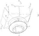
- the Fig. 7 shows a perspective view of another embodiment of an air guide assembly 1 and a sectional view of this air guide assembly 1 in a channel-shaped housing 30 with a centrifugal fan 40th
- This embodiment has supplementary to the execution of the Fig. 6 at the air corpse 21 on a plurality of rectangular and curved shipsleiterieln 23 which extend in the radial direction to the inner side 31 of the housing 30.
- the angle of attack ⁇ of the guide vanes 23 with respect to the axial direction is optionally carried out at an angle of 0 ° to 60 °, as well as in the embodiment of Fig. 8 is shown.
- the guide vanes 23 cause the existing twist of the air as lossless redirect in the axial direction, which increases the efficiency of the fan.
- profile shape typical profile shapes (for example NACA profiles) or even simple sheet metal geometries can be used.
- the ratio SL / La between the chord length SL and the diameter La of the centrifugal fan is preferably between 0.05 and 0.4.
- the ratio between the axial distance Xi of the guide vanes 23 and the diameter La of the centrifugal fan is preferably between 0 and 0.8.
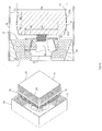
- FIG. 8 and 9 further embodiments of an air guide 1 are shown.
- the air guide vanes 23 are similarly oriented, as in the embodiment of FIG. 7 , but attached to the housing 30.
- the first and second guide plate formation 10, 20 connected to each other.
- the dimensions are chosen as follows: the ratio Xd / La is between 0.3 and 0.7, the ratio Xe / La is between 0.1 and 1.0, the ratio of Ya / La is between 1.5 and 2,0 and the angle ⁇ is between 45 ° and 80 °, wherein the baffles 21 of the downstream Leitblechformation 20 extend approximately parallel to the wall of the housing 30.
- FIGS. 10 and 11 show views of a further embodiment of an air guide assembly 1.
- the guide plate formation 20 consists of a multi-folded sheet metal. This is folded in such a way that additional guide vanes 21s are formed which minimize the twist and deflect the flow of the air as loss-free as possible in the axial direction.
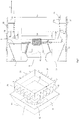
- Fig. 12 is an execution similar to the FIG. 6 shown, however, the baffle formations 10, 20 of perforated plates with holes 14, 24 are formed.
- the underlying cavity is lined with sound-absorbing material, which leads to an increased noise reduction. Such a sound-absorbing measure is also possible with the other versions.
Landscapes
- Engineering & Computer Science (AREA)
- Mechanical Engineering (AREA)
- General Engineering & Computer Science (AREA)
- Chemical & Material Sciences (AREA)
- Combustion & Propulsion (AREA)
- Structures Of Non-Positive Displacement Pumps (AREA)
Abstract
Description
- Die Erfindung betrifft eine Luftleitanordnung für einen Radialventilator in einer raumlufttechnischen Lüftungsanlage vorzugsweise für ein kanalförmiges Gehäuse mit einem rechteckigen, runden oder quadratischen Querschnitt.
- Luftleitanordnungen und Luftumlenkvorrichtungen sind im Stand der Technik in unterschiedlichen Ausführungen bekannt. Einfachste Ausführungsformen sind Bleche, mit denen die Strömungsrichtung in einem Luftstrom umgelenkt wird.
- Eine Luftumlenkvorrichtung ist zum Beispiel aus der
DE 89 08 987 U bekannt. Bei dieser bekannten Anordnung findet die Umlenkung der Luft von der radialen in die axiale Richtung ausschließlich an der Gehäusewandung des Förderkanals statt. Die von den Schaufeln nach außen geförderte Luft tritt dabei in radialer Richtung auf die Wandungen des Förderkanalgehäuses auf. Dies führt zu starken Strömungsverlusten und zu einer starken Lärmentwicklung. Zudem kann es hierbei in dem Abströmspalt zwischen Abströmblech und Gehäusewand gegenüberliegenden, trennblechnahen Bereich zu starken Turbulenzen kommen, die nicht nur die erwähnten Nachteile verstärken, sondern vor allem auch einer Volumenstromregelung durch Veränderung des Spalts zwischen Einströmdüse und Einströmstutzen des Ventilatorrads ungünstig entgegenstehen. - Die
DE 4129211 A1 beschäftigt sich damit eine sanfte Umlenkung des geförderten Mediums zu erreichen und Turbulenzen im dem Abströmspalt gegenüberliegenden Bereich zu vermeiden. Dies wird dadurch gelöst, dass der Förderkanal mit einem zumindest den ansaugseitigen Randbereich des Radialventilatorlaufrads mit Abstand umfassenden, in Transportrichtung des Gases bis auf den Förderkanalquerschnitt sich erweiternden Umlenktrichter versehen ist. - Radialventilatoren sind allgemein bekannt und umfassen ein mittels eines Antriebsmotors angetriebenes Laufrad. Das Laufrad weist im Allgemeinen auf seiner Abströmseite eine Deckscheibe auf, an die die Laufradflügel angrenzen. Die Luft wird bei einem Radialventilator üblicherweise parallel zur Antriebsachse des Radialventilators, somit axial angesaugt und durch die Rotation des Laufrades um 90° umgelenkt und radial ausgeblausen. Damit wird die angesaugte Luft somit radial nach außen, d. h. in Richtung der Wandung eines kanalförmigen Gehäuses geblasen. Damit die Luft an der Druckseite des Radialventilators, d. h. an der Abströmseite, wieder in die Hauptströmungsrichtung fließt, muss der Luftstrom erneut an der Wandung um 90° umgelenkt werden. Dabei entstehen Wirbel und ein unerwünschter Druckverlust, der den Gesamt-Wirkungsgrad eines Radialventilators in einer solchen Anwendung vermindert.
- Der Erfindung liegt deshalb die Aufgabe zugrunde, die vorgenannten Nachteile zu vermeiden und eine Anordnung anzugeben, bei der die Abströmung der beförderten Luft- oder Gasmenge des Radialventilators verbessert wird, so dass infolgedessen der Wirkungsgrad aufgrund eines geringeren Druckverlustes erhöht wird. Ziel ist es damit, den von einem Radialventilator angesaugten Luftstrom möglichst verlustfrei in ein kanalförmiges Gehäuse ausströmen zu lassen.
- Diese Aufgabe wird durch die Merkmalskombination gemäß Anspruch 1 gelöst.
- Ein Grundgedanke der Erfindung besteht darin, den radialen Luftstrom des Radialventilators über eine bzw. mehrere Leitblechformationen aus spezifisch angeordneten und geformten Leitblechen abströmseitig hinter einem Radialventilator so anzuordnen, dass der vorhandene Drall abgebaut wird, indem die Leitbleche entgegen der Drallrichtung eingesetzt sind. Zusätzlich wird der Strömungsquerschnitt entlang der Leitblechformation erweitert, um dadurch einen Diffusoreffekt zu erzielen.
- Erfindungsgemäß ist daher eine Luftleitanordnung vorgesehen, die ausgebildet ist für eine raumlufttechnische Lüftungsanlage mit einem kanalförmigen Gehäuse und einem auf einer Querschnittsebene in dem Gehäuse angeordneten Radialventilator, wobei die Luftleitanordnung wenigstens eine Leitblechformation aus mehreren unterschiedlich zueinander orientierten Luftleitblechen umfasst, wobei ein Luftdurchtrittskanal zwischen den Luftleitblechen der Leitblechformation(en) und dem Inneren des Gehäuse so ausgebildet wird, dass der vorhandene Drall abgebaut wird, indem die Leitbleche entgegen der Drallrichtung orientiert sind.
- In einer bevorzugten Ausgestaltung der Erfindung ist vorgesehen, dass ferner ansaugseitig eine weitere Leitblechformation als eine im Wesentlichen pyramidenförmige und/oder trichterförmige Leitblechformation mit einem quadratischen oder rechteckigen Querschnitt ausgebildet ist, die bevorzugt dem Querschnitt des kanalförmigen Gehäuses entspricht in welches die Luftleitanordnung bestimmungsgemäß eingesetzt werden soll.
- Weiter vorteilhaft ist es, wenn diese ansaugseitige Leitblechformation aus vier im Wesentlichen flachen, trapezförmigen Luftleitblechen geformt bzw. ausgebildet wird, welche jeweils unter einem Anstellwinkel α an einer in der Querschnittsebene des Gehäuses angeordneten, als Düse wirkenden mit einer zentralen Öffnung versehenen Basisplatte verbunden sind. Somit wird eine pyramidenförmige Leitblechformation geschaffen, bei denen die Seitenwände bevorzugt unter einem Anstellwinkel α zwischen 45° und 80° gegenüber der Querschnittsebene orientiert sind.
- In einer ebenfalls bevorzugten Ausgestaltung der Erfindung ist vorgesehen, dass die abströmseitig angeordnete Leitblechformation, die abströmseitig hinter dem Radialventilator vorzusehen ist, als eine im Wesentlichen pyramiden- oder trichterförmige Leitblechformation mit einer in der Querschnittsebene des Gehäuses verlaufenden Basis mit einem im Wesentlichen quadratischen oder rechteckigen Querschnitt ausgebildet ist.
- Betreffend der Ausgestaltung der abströmseitigen Leitblechformation können die nachfolgend beschriebenen unterschiedlichen Anordnungen von Leitblechen gewählt werden.
- In einer ersten vorteilhaften Ausgestaltung der abströmseitigen Leitblechformation gemäß der Erfindung ist vorgesehen, dass diese aus vier paarweise angeordneten jeweils zweifach gekanteten Luftleitblechen gebildet wird, die so gekantet und zueinander angeordnet sind, dass sich die zuvor erwähnte pyramiden- oder trichterförmige Leitblechformation ergibt.
- Hierzu bilden die einzelnen Leitbleche jeweils einen dreieckigen Blechabschnitt aus, der jeweils ein Teilsegment der Basis der abströmseitigen Leitblechformation bildet. An diesen dreieckigen Blechabschnitt schließt sich ein dazu im Wesentlichen in Axialrichtung des Radialventilators umgebogener bzw. abgekanteter rechteckiger Blechabschnitt mit jeweils zwei Seitenkanten an, wobei die Leitbleche vorzugsweise um einen Winkel von 0° bis 20° in Bezug auf die Axialrichtung verdreht angeordnet sind. Bevorzugt ist ein weiterer Belchabschnitt an dem jeweiligen Leitblech als abgewinkelte Finne und zwar bevorzugt am dreieckigen Blechabschnitt ausgebildet.
- Weiter ist mit Vorteil vorgesehen, dass der Biegewinkel der beiden Leitbleche eines Leitblechpaares der jeweiligen rechteckigen Blechabschnitte gegenüber den dreieckigen Blechabschnitten unterschiedlich ist und zwar mit einem Differenzwinkel ϕ von etwa 3° bis 10°. Alternativ sind auch gleiche Winkel denkbar.
- In einer anderen vorteilhaften Ausgestaltung der abströmseitigen Leitblechformation gemäß der Erfindung ist vorgesehen, dass diese aus vier jeweils entlang einer Kante abgewinkelten Luftleitblechen gebildet wird, welche jeweils mit einem ersten flachen trapezförmigen Leitblechabschnitt, der unter einem definierten Anstellwinkel an einer in der Querschnittsebene angeordneten Basisplatte verbunden sind, ausgebildet sind. Weiter bevorzugt ist vorgesehen, dass die abgewinkelten Luftleitbleche angrenzend an die besagte Kante jeweils einen abströmseitigen flachen vorzugsweise ebenfalls trapezförmigen Leitblechabschnitt ausbilden, der unter einem größeren Anstellwinkel, als der Anstellwinkel des zuvor genannten Leiterblechabschnitts gegenüber der Querschnittsebene orientiert ist.
- Es ist weiter mit Vorteil vorgesehen, dass die erste und/oder zweite Leitblechformation zumindest eine Mehrzahl an vorzugsweise rechteckigen und/oder gebogenen Luftleitflügeln aufweist, die sich in Radialrichtung erstrecken. Dabei kann die Mehrzahl der Luftleitflügel an der Außenfläche der Luftleitbleche der abströmseitigen Leitblechformation oder an der Innenfläche der ersten Leitblechformation verbunden oder angeordnet sein. Im ersten Fall erstreckt sich die Mehrzahl der Luftleitflügel nach Außen möglichst soweit, dass diese bis zur Innenwand des Gehäuses im eingebauten Zustand der Luftleitanordnung reichen.
- Im abströmseitigen Fall erstreckt sich die Mehrzahl der Luftleitflügel nach Innen möglichst soweit, dass sich diese im eingebauten Zustand der Luftleitanordnung bis zur Außenkontur des Radialventilators (in Axialrichtung betrachtet) erstrecken.
- Ein weiterer Aspekt der vorliegenden Erfindung betrifft eine wie zuvor beschriebene Luftleitanordnung, die in einem kanalförmigen Gehäuse einer raumlufttechnischen Lüftungsanlage zumindest teilweise um einen Radialventilator herum angeordnet ist, wobei eine wie zuvor beschriebene Leitblechformation abströmseitig hinter dem Radialventilator angeordnet ist.
- Weiter vorteilhaft ist es, wenn die Geometrien und die Ausrichtung der Leitblechformationen innerhalb bestimmter Größen und Orientierung gewählt wird, die bei der Beschreibung der bevorzugten Ausführungsbeispiele näher beschrieben und angegeben werden.
- Andere vorteilhafte Weiterbildungen der Erfindung sind in den Unteransprüchen gekennzeichnet bzw. werden nachstehend zusammen mit der Beschreibung der bevorzugten Ausführung der Erfindung anhand der Figuren näher dargestellt. Es zeigen:
- Fig. 1
- eine Schnittansicht durch ein kanalförmiges Gehäuse mit einem auf einer Querschnittsebene in dem Gehäuse angeordneten Radialventilator;
- Fig. 2
- eine perspektivische Ansicht eines ersten Ausführungsbeispiels einer Luftleitanordnung sowie eine Schnittansicht dieser Luftleitanordnung in einem kanalförmiges Gehäuse mit einem Radialventilator;
- Fig. 3
- Detailansichten der Luftleitbleche aus
Figur 2 ; - Fig. 4
- eine andere perspektivische Ansicht des Ausführungsbeispiels der Luftleitanordnung aus
Figur 2 ; - Fig. 5
- eine Seitenansicht des Ausführungsbeispiels der Luftleitanordnung aus
Figur 2 bzw.Fig. 4 ; - Fig. 6
- eine perspektivische Ansicht eines weiteren Ausführungsbeispiels einer Luftleitanordnung sowie eine Schnittansicht dieser Luftleitanordnung in einem kanalförmiges Gehäuse mit einem Radialventilator;
- Fig. 7
- eine perspektivische Ansicht eines weiteren Ausführungsbeispiels einer Luftleitanordnung sowie eine Schnittansicht dieser Luftleitanordnung in einem kanalförmiges Gehäuse mit einem Radialventilator;
- Fig. 8
- eine perspektivische Ansicht eines weiteren Ausführungsbeispiels einer Luftleitanordnung sowie eine Schnittansicht dieser Luftleitanordnung in einem kanalförmiges Gehäuse mit einem Radialventilator;
- Fig. 9
- eine perspektivische Ansicht eines weiteren Ausführungsbeispiels einer Luftleitanordnung sowie eine Schnittansicht dieser Luftleitanordnung in einem kanalförmiges Gehäuse mit einem Radialventilator;
- Fig. 10
- eine perspektivische Ansicht eines weiteren Ausführungsbeispiels einer Luftleitanordnung sowie eine Schnittansicht dieser Luftleitanordnung in einem kanalförmiges Gehäuse mit einem Radialventilator;
- Fig. 11
- weitere perspektivische Ansichten des Ausführungsbeispiels der Luftleitanordnung aus
Figur 10 und - Fig. 12
- eine perspektivische Ansicht eines weiteren Ausführungsbeispiels einer Luftleitanordnung mit einer Schalldämpferfunktion sowie eine Schnittansicht dieser Luftleitanordnung in einem kanalförmiges Gehäuse mit einem Radialventilator.
- Im Folgenden wird die Erfindung anhand der
Figuren 1 bis 12 mit Hilfe der Beschreibung der verschiedenen Ausführungsformen näher erläutert, wobei gleiche Bezugszeichen auf strukturell und/oder funktional gleiche Bauteile hinweisen. - In der
Fig. 1 ist eine Schnittansicht durch ein kanalförmiges Gehäuse 30 einer raumlufttechnischen Lüftungsanlage gezeigt in dem ein Radialventilator 40 mit Ventilatorschaufeln 41 angeordnet ist, die von einem Motor 42 in Rotation versetzt werden können. Angedeutet ist eine Luftströmung, deren Verlauf schematisch mit Hilfe der dargestellten Pfeile gezeigt ist. Der Radialventilator saugt axial über die Ansaugöffnung A Luft an, die dann im Bereich der Ventilatorschaufeln 41 zunächst in eine radiale und danach abströmseitig wieder in eine axiale Strömung überführt wird. - In der
Fig. 6 ist eine perspektivische Ansicht eines Ausführungsbeispiels einer Luftleitanordnung 1 sowie daneben eine Schnittansicht dieser Luftleitanordnung 1 in einem kanalförmigen Gehäuse 30 mit einem Radialventilator 40 gezeigt. Zunächst wird diese beispielhafte Ausführungsform beschrieben, um die Geometrien der Luftleitanordnung 1 insbesondere in Bezug auf den Radialventilator 40 und das Gehäuse 30 näher zu erläutern. - Die Luftleitanordnung 1 ist um den auf der Querschnittsebene E angeordneten Radialventilator 40 herum angeordnet. Diese Luftleitanordnung 1 zeigt ergänzend eine ansaugseitige Leitblechformation 10 aus vier jeweils im 90° Winkel-Versatz zueinander orientierten Luftleitblechen 11. Diese können auch aus einem einzigen entsprechend gezeigten Blech gebildet sein, sowie abströmseitig eine erfindungsgemäße Leitblechformation 20 aus mehreren entlang einer Kantlinie K abgekanteter Luftleitbleche 21. Zwischen den Luftleitblechen 11, 21 der Leitblechformationen 10, 20 und dem Inneren 31 des Gehäuse 30 ist ein Luftdurchtrittskanal 2 ausgebildet, wobei aufgrund der unterschiedlichen Anstellwinkel ß1, ß2 der Abschnitte der Luftleitbleche 21 der effektive Strömungsquerschnitt für die vom Radialventilator 40 geförderte Luft in Strömungsrichtung S in diesem Bereich zunimmt.
- Die Leitblechformation 10 stellt eine im Wesentlichen trichter- bzw. pyramidenförmige Leitblechformation 10 mit einem quadratischen Querschnitt dar. Diese ist aus vier flachen, miteinander verbundenen trapezförmigen Luftleitblechen 11 ausgebildet, welche jeweils unter einem gleichen Anstellwinkel α an einer in der Querschnittsebene E angeordneten, als Düse wirkenden mit einer zentralen Öffnung versehenen Basisplatte 12 verbunden sind. Der Anstellwinkel α der Luftleitbleche 11 ist bevorzugt zwischen 45° und 80°.
- Die abströmseitige Leitblechformation 20 wird aus einem entlang einer Kante K abgewinkelten (gekanteten) Luftleitblech 21 gebildet, das vier Blechsegmente ausbildet. Diese Leitblechformation 20 stellt eine im Wesentlichen trichterförmige Leitblechformation mit einem quadratischen Querschnitt dar. Jedes der vier Segmente des Luftleitbelchs 21 weist einen ersten flachen Leitblechabschnitt 21a auf, der unter einem Anstellwinkel ß1 an der in der Querschnittsebene E angeordneten Basisplatte 22 verbunden ist. Jedes der vier Segmente des Luftleitbelchs 21 weist ferner einen abströmseitigen (sich an den ersten Leitblechabschnitt 21a anschließenden) flachen Leitblechabschnitt 21 b auf, der unter einem Anstellwinkel ß2 gegenüber der Querschnittsebene E orientiert ist. Der Anstellwinkel ß1 ist bevorzugt zwischen 30° und 90°, während der Anstellwinkel ß2 bevorzugt zwischen 90° und 100° beträgt.
- Das Verhältnis Xa/La des Abstands Xa der Kante K des Luftleitbelchs 21 bis zur Basis 22 zum Durchmesser La des Radialventilators liegt zwischen 0,05 und 0,5 liegt. In dieser Ausführung der Erfindung wird durch die gekantete Form der abströmseitigen Leitblechformation 20 eine Erweiterung des Strömungsquerschnitts bewirkt. Dies führt zu einer Verringerung der Strömungsgeschwindigkeit und somit zu einer Steigerung des statischen
Druckes. Die axiale Länge des Leitblechabschnitts 21 b von der Kante K bis zu Hinterkante gemessen, ist mit Xb bezeichnet. Eine bevorzugte Auswahl für das Verhältnis Xb/ La liegt im Bereich von 0,15 bis 0,8. Bevorzugte Größen für Yb/LA liegen zwischen 1,1 und 2,0. - In den
Figuren 2 bis 5 sind Ansichten eines alternativen Ausführungsbeispiels einer Luftleitanordnung 1 in einem kanalförmigen Gehäuse 30 mit einem Radialventilator 40 gezeigt. Die beiden Luftleitformationen 10, 20 sind hier ebenfalls im Wesentlichen trichter- bzw. pyramidenförmig. Die erste Leitblechformation 10 ist, wie in der zuvor beschriebenen Ausführung nach derFig. 6 ausgebildet. - Die zweite Leitblechformation 20 ist aus vier paarweise angeordneten zweifach gekanteten Luftleitblechen 21 geformt. Die Form der einzelnen Luftleitbleche 21 ist in der
Figur 3 gut zu erkennen. Hierzu bilden die einzelnen Leitbleche 21 jeweils einen dreieckigen Blechabschnitt 21d aus, der jeweils ein Teilsegment der Basis 22 der abströmseitigen Leitblechformation 20 bildet. An diesen dreieckigen Blechabschnitt 21d schließt sich ein dazu im Wesentlichen in Axialrichtung des Radialventilators 40 umgebogener bzw. abgekanteter rechteckiger Blechabschnitt 21 e mit jeweils zwei Seitenkanten 21k an, wobei die Leitbleche vorzugsweise um einen Winkel ϕ von 0° bis 20° in Bezug auf die Axialrichtung verdreht angeordnet sind (sieheFig. 5 ). Bevorzugt ist ein weiterer Belchabschnitt 21f an dem jeweiligen Luftleitblech 21 als abgewinkelte Finne und zwar bevorzugt am dreieckigen Blechabschnitt 21 d ausgebildet. - Der Biegewinkel ß1 der beiden Leitbleche eines Leitblechpaares der jeweiligen rechteckigen Blechabschnitte 21e gegenüber den dreieckigen Blechabschnitten 21d ist unterschiedlich und zwar dergestalt, dass dieser Differenzwinkel etwa +/- 3° bis +/-10° beträgt, was in der Schnittansicht der
Fig. 2 zu sehen ist. Dieser Differenzwinkel ergibt sich dadurch, dass das eine Blech um die Ankathete und das andere Blech um die Hypotenuse gedreht wird. - Das Verhältnis Yb/La des äußeren Kantenmaßes der äußeren Leitgeometrie Yb und dem Durchmesser La des Radialventilators entspricht typischerweise Werte zwischen 1,5 - 2,0. Für den Winkel ß1 werden typischerweise Winkel zwischen 20 - 80°verwendet. Das Verhältnis zwischen dem Abstand Xc der Basis 22 der abströmseitigen Leitblechformation 20 zu dem Durchmesser La des Radialventilators liegt vorzugsweise in dem folgenden Wertebereich: 0 < Xc/ La <= 0,8.
- Die
Fig. 7 zeigt eine perspektivische Ansicht eines weiteren Ausführungsbeispiels einer Luftleitanordnung 1 sowie eine Schnittansicht dieser Luftleitanordnung 1 in einem kanalförmigen Gehäuse 30 mit einem Radialventilator 40. - Diese Ausführung weist ergänzend zur Ausführung nach der
Fig. 6 an den Luftleiblechen 21 eine Mehrzahl an rechteckigen und gebogenen Luftleitflügeln 23 auf, die sich in Radialrichtung bis zur Innenseite 31 des Gehäuses 30 erstrecken. Der Anstellwinkel ε der Leitflügel 23 gegenüber der Axialrichtung erfolgt wahlweise unter einem Winkel von 0° bis 60°, so wie dies auch bei der Ausführung derFig. 8 dargestellt ist. - In einer solchen Ausführung bewirken die Leitflügel 23 den vorhandenen Drall der Luft möglichst verlustfrei in axiale Richtung umzulenken, was den Wirkungsgrad des Ventilators erhöht. Als Profilform können typische Profilformen (z.B. NACA-Profile) oder auch einfache Blechgeometrien verwendet werden. Das Verhältnis SL/La zwischen der Sehnenlänge SL und dem Durchmesser La des Radialventilators liegt bevorzugt zwischen 0,05 und 0,4. Das Verhältnis zwischen dem axialen Abstand Xi der Leitflügel 23 und dem Durchmesser La des Radialventilators liegt bevorzugt zwischen 0 und 0,8.
- In den
Fig. 8 und9 sind weitere Ausführungsbeispiele einer Luftleitanordnung 1 gezeigt. In derFigur 8 sind die Luftleitflügel 23 ähnlich orientiert, wie in der Ausführung derFigur 7 , jedoch am Gehäuse 30 befestigt. Für die Ausgestaltung und Orientierung der Leitflügel 23 wird auf die Ausführungen derFiguren 6 und7 verweisen, wobei der radiale Abstand zwischen den innen liegenden Stirnseiten der Luftleitflügel Yb dem Durchmesser La des Radialventilators 40 entspricht, d.h. Yb = La. - Bei der
Fig. 9 sind sozusagen die erste und zweite Leitblechformation 10, 20 miteinander verbunden. Die Abmessungen sind dabei folgendermaßen zu wählen: das Verhältnis Xd/ La liegt zwischen 0,3 und 0,7, das Verhältnis Xe/ La liegt zwischen 0,1 und 1,0, das Verhältnis von Ya/ La liegt zwischen 1,5 und 2,0 und der Winkel α liegt zwischen 45° und 80°, wobei die Leitbleche 21 der abströmseitigen Leitblechformation 20 in etwa parallel zu der Wand des Gehäuses 30 verlaufen. - Die
Figuren 10 und11 zeigen Ansichten eines weiteren Ausführungsbeispiels einer Luftleitanordnung 1. In dieser Ausführung besteht die Leitblechformation 20 aus einem mehrfach gekanteten Blech. Dieses wird derart gekantet, dass zusätzliche Leitschaufeln 21s entstehen, die den Drall minimieren und die Strömung der Luft möglichst verlustfrei in axiale Richtung umlenken. - In der
Fig. 12 ist eine Ausführung ähnlich derFigur 6 gezeigt, allerdings sind die Leitblechformationen 10, 20 aus Lochblechen mit Löchern 14, 24 gebildet. Der dahinter liegende Hohlraum ist mit schalldämmendem Material ausgekleidet, was zu einer erhöhten Schallreduktion führt. Eine solche schalldämmende Maßnahme ist auch mit den weiteren Ausführungen möglich.
Claims (22)
- Luftleitanordnung (1) ausgebildet für eine raumlufttechnische Lüftungsanlage mit einem kanalförmigen Gehäuse (30) und einer auf einer Querschnittsebene (E) in dem Gehäuse (30) angeordneten Luftfördereinrichtung (40), wobei die Luftleitanordnung (1) abströmseitig wenigstens eine Leitblechformation (20) mit relativ zueinander orientierter Luftleitblechen (21) umfasst, wobei ein Luftdurchtrittskanal (2) zwischen den Luftleitblechen (21) der Leitblechformationen (20) und dem Inneren (31) des Gehäuse (30) ausgebildet wird und die Luftleitbleche (21) zum Erzielen einer Diffusorwirkung so angeordnet sind, dass der effektive Strömungsquerschnitt für die von der Luftfördereinrichtung (40) geförderten Luft in Strömungsrichtung (S) zumindest partiell zunimmt und/oder sich deren Anstellwinkel oder Orientierung in Strömungsrichtung (S) ändert.
- Luftleitanordnung (1) nach Anspruch 1, dadurch gekennzeichnet, dass abströmseitig zwei oder mehrere Leitblechformationen (20) aus relativ zueinander orientierter Luftleitbleche (21) angeordnet sind.
- Luftleitanordnung (1) nach Anspruch 2, dadurch gekennzeichnet, dass die zwei oder mehrere Leitblechformationen (20) abströmseitig in einer Kaskadenanordnung hintereinander angebracht sind.
- Luftleitanordnung (1) nach einem der Ansprüche 1-3, dadurch gekennzeichnet, dass ansaugseitige zusätzlich eine Leitblechformation (10) aus relativ zueinander orientierter Luftleitbleche (11) angeordnet ist.
- Luftleitanordnung (1) nach Anspruch 4, dadurch gekennzeichnet, dass die ansaugseitige Leitblechformation (10) als eine im Wesentlichen trichterförmige Leitblechformation (10) mit einem quadratischen oder rechteckigen Querschnitt ausgebildet ist.
- Luftleitanordnung (1) nach einem der Ansprüche 1 - 5, dadurch gekennzeichnet, dass die abströmseitige Leitblechformation(en) (20) als eine im Wesentlichen pyramiden- oder trichterförmige Leitblechformation (20) mit einer Basis (22) mit einem im Wesentlichen quadratischen oder rechteckigen Querschnitt ausgebildet ist bzw. sind.
- Luftleitanordnung (1) nach einem der vorhergehenden Ansprüche, dadurch gekennzeichnet, dass die abströmseitige Leitblechformation (20) aus vier paarweise angeordneten zweifach gekanteten Luftleitblechen (21) gebildet wird, welche wenigstens eine dreieckige Blechform ausbilden, die jeweils ein Teilsegment der Basis (22) bilden an das sich ein dazu im Wesentlichen in Axialrichtung (S) umgebogenes rechteckiges Blechteil mit jeweils zwei Seitenkanten (21 k) anschließt, wobei die Leitbleche (21) gegenüber die Axialrichtung (S) verdreht angeordnet sind, so dass deren Seitenkanten (21k) in Bezug auf die Axialrichtung (S) in einen Winkel von 0° bis 20° ausgerichtet sind.
- Luftleitanordnung (1) nach Anspruch 7, dadurch gekennzeichnet, dass der Winkel (ϕ) des im Wesentlichen in Axialrichtung (S) umgebogenen rechteckigen Blechteile der Luftleitbleche (21) gegenüber der Basis (22) sich bei jeweils unmittelbar benachbarter Luftleitbleche (21) unterscheidet und vorzugsweise um etwa 3° bis 10° voneinander abweicht.
- Luftleitanordnung (1) nach einem der Ansprüche 1 - 6, dadurch gekennzeichnet, dass die zweite Leitblechformation (20) aus einem über eine Kante (K) abgewinkelten Luftleitblech (21) mit vier Blechsegementen gebildet wird, welche jeweils mit einem ersten flachen Leitblechabschnitt (21 a), der unter einem Anstellwinkel (ß1) an einer in der Querschnittsebene (E) angeordneten Basisplatte (22) verbunden sind, wobei der Anstellwinkel (ß1) bevorzugt zwischen 20° und 80° liegt.
- Luftleitanordnung (1) nach Anspruch 9, dadurch gekennzeichnet, dass die abgewinkelten Luftleitbleche (21) angrenzend an die Kante (K) jeweils einen abströmseitigen flachen Leitblechabschnitt (21 b) ausbilden, der unter einem zum Anstellwinkel (ß1) unterschiedlichen, vorzugsweise jeweils größeren Anstellwinkel (ß2) gegenüber der Querschnittsebene (E) orientiert sind, wobei der Winkel (ß1) vorzugsweise 30° bis 90° und der Winkel (ß2) vorzugsweise 90° bis 100° beträgt und weiter vorzugsweise das Verhältnis des Abstands (Xa) der Kante (K) bis zur Basis (22) zum Durchmesser des Radialventilators (La) zwischen 0,05 und 0,5 liegt.
- Luftleitanordnung (1) nach einem der vorhergehenden Ansprüche 1 bis 6, dadurch gekennzeichnet, dass die abströmseitige(n) Leitblechformation(en) (20) zumindest eine Mehrzahl an vorzugsweise rechteckigen und/oder gebogenen Luftleitflügeln (23) aufweist bzw. aufweisen, die sich in Radialrichtung erstrecken.
- Luftleitanordnung (1) nach Anspruch 11, dadurch gekennzeichnet, dass der Anstellwinkel (ε) der Leitflügel (23) unter einem Winkel von 0° bis 60° erfolgt.
- Luftleitanordnung (1) nach Anspruch 11 oder 12, dadurch gekennzeichnet, dass die Luftleitflügel (23) an der Außenfläche der Luftleitbleche (21) der abströmseitigen Leitblechformation (20) oder an der Innenfläche der ansaugseitigen Leitblechformation (10) verbunden oder angeordnet sind.
- Luftleitanordnung (1) nach einem der vorhergehenden Ansprüche 1 bis 13, dadurch gekennzeichnet, dass die Luftfördereinrichtung (40) ein Radialventilator ist.
- Luftleitanordnung (1) nach einem der vorhergehenden Ansprüche 1 bis 14, angeordnet in einem kanalförmigen Gehäuse (30) einer raumlufttechnischen Lüftungsanlagen, wobei die Luftfördereinrichtung als Radialventilator (40) ausgebildet ist.
- Luftleitanordnung (1) angeordnet in einem kanalförmigen Gehäuse (30) gemäß den Merkmalen von Anspruch 15, wobei die ansaugseitige Leitblechformation (10) zumindest teilweise um den Radialventilator (40) herum angeordnet ist, während die zweite Leitblechformation (20) abströmseitig hinter dem Radialventilator (40) angeordnet ist.
- Luftleitanordnung nach Anspruch 16, wobei das Verhältnis der axialen Länge (Xa) der Luftleitblechen (11) der ersten Leitblechformation (10) und dem Durchmesser (La) des Radialventilators (30) zwischen 0,3 und 0,7 beträgt und wobei das Verhältnis des Kantenmaßes der äußeren Kanten (11k) der Luftleitbleche (11) der ersten Leitblechformation (10) und dem Durchmesser (La) des Radialventilators (30) zwischen 1,5 und 2 liegt.
- Luftleitanordnung einem der Ansprüche 15 bis 17, wobei das Verhältnis der axialen Länge (Xb) der Luftleitblechen (21) der abströmseitigen Leitblechformation (20) und dem Durchmesser (La) des Radialventilators (30) zwischen 0,05 und 0,8 beträgt.
- Luftleitanordnung nach einem der Ansprüche 15 bis 18, wobei das Verhältnis des Kantenmaßes der äußeren Kanten (21k) der Luftleitbleche (21) der abströmseitigen Leitblechformation (20) zu dem Durchmesser (La) des Radialventilators (30) zwischen 1,1 und 2 liegt.
- Luftleitanordnung nach einem der Ansprüche 15 bis 19, wobei das Verhältnis des Abstands (Xc) der Basis (22) der abströmseitigen Leitplattenformation (20) zum Radialventilator (40) zu dem Durchmesser (La) des Radialventilators (30) zwischen 0 und 0,8 liegt.
- Luftleitanordnung nach einem der Ansprüche 1 bis 20, wobei die Leitbleche wenigstens der Leitblechformation (20) aus Lochblechen mit Löchern (24) gebildet sind.
- Luftleitanordnung nach einem der Ansprüche 1 bis 21, wobei ein jeweils hinter den Leitblechen (21) gebildeter Hohlraum mit schalldämmendem Material ausgekleidet ist, um dadurch eine Schall- und/oder Geräuschreduktion zu bewirken.
Applications Claiming Priority (1)
| Application Number | Priority Date | Filing Date | Title |
|---|---|---|---|
| DE102017104779.4A DE102017104779A1 (de) | 2017-03-07 | 2017-03-07 | Luftleitanordnung |
Publications (2)
| Publication Number | Publication Date |
|---|---|
| EP3372838A1 true EP3372838A1 (de) | 2018-09-12 |
| EP3372838B1 EP3372838B1 (de) | 2020-09-16 |
Family
ID=61480502
Family Applications (1)
| Application Number | Title | Priority Date | Filing Date |
|---|---|---|---|
| EP18160318.4A Not-in-force EP3372838B1 (de) | 2017-03-07 | 2018-03-06 | Raumlufttechnische lüftungsanlage mit einer luftleitanordnung |
Country Status (3)
| Country | Link |
|---|---|
| EP (1) | EP3372838B1 (de) |
| CN (1) | CN207033842U (de) |
| DE (2) | DE102017104779A1 (de) |
Cited By (3)
| Publication number | Priority date | Publication date | Assignee | Title |
|---|---|---|---|---|
| WO2020094443A1 (de) * | 2018-11-07 | 2020-05-14 | ebm-papst AB | Luftleitanordnung für eine lüftungsanlage |
| WO2020099183A1 (de) * | 2018-11-16 | 2020-05-22 | Ebm-Papst Mulfingen Gmbh & Co. Kg | Diagonalventilator mit optimiertem gehäuse |
| CN112780608A (zh) * | 2021-01-05 | 2021-05-11 | 浙江友邦集成吊顶股份有限公司 | 一种气流扩散效果好的风机 |
Families Citing this family (3)
| Publication number | Priority date | Publication date | Assignee | Title |
|---|---|---|---|---|
| US10443624B2 (en) * | 2017-03-28 | 2019-10-15 | Acoustiflo, Llc | Modular fan unit apparatus and methods |
| DE102018211809A1 (de) * | 2018-07-16 | 2020-01-16 | Ziehl-Abegg Se | Gehäuse für einen Ventilator und Ventilator |
| DE102018132002A1 (de) * | 2018-12-12 | 2020-06-18 | Ebm-Papst Mulfingen Gmbh & Co. Kg | Ventilationseinheit |
Citations (6)
| Publication number | Priority date | Publication date | Assignee | Title |
|---|---|---|---|---|
| FR1260792A (fr) * | 1960-04-01 | 1961-05-12 | Neu Sa | Ventilateur centrifugo-axial |
| FR1603749A (de) * | 1968-09-18 | 1971-05-24 | ||
| DE9110195U1 (de) * | 1991-08-17 | 1991-10-24 | Neuhaus, Gerhard, Dipl.-Ing., 6301 Fernwald | Ventilator |
| EP2574794A2 (de) * | 2011-09-30 | 2013-04-03 | TROX GmbH | Lüftungsbauteil |
| US20130118352A1 (en) * | 2010-03-04 | 2013-05-16 | Berling Gmbh | Air Extraction Device and Method for Removing Particles Carried by an Air Stream |
| JP2016114047A (ja) * | 2014-12-18 | 2016-06-23 | 三星電子株式会社Samsung Electronics Co.,Ltd. | ディフューザ及び空気調和装置 |
Family Cites Families (6)
| Publication number | Priority date | Publication date | Assignee | Title |
|---|---|---|---|---|
| DE7910066U1 (de) | 1979-04-06 | 1979-08-09 | Freisberg, Gregor, 5411 Nauort | Axialgeblaese zum einbau in lueftungssysteme |
| DE8908987U1 (de) | 1989-07-25 | 1989-11-02 | Neuhaus, Gerhard, Dipl.-Ing., 6301 Fernwald | Ventilatoraggregat |
| DE4129211A1 (de) | 1991-09-03 | 1993-03-04 | Al Ko Therm Maschf | Vorrichtung zum foerdern von gasen |
| DE202010012876U1 (de) | 2010-11-12 | 2011-03-24 | Lin, Cheng-Chang, Shengang Township | Luftführung für Ventilator |
| DE202010016820U1 (de) | 2010-12-21 | 2012-03-26 | Ebm-Papst Mulfingen Gmbh & Co. Kg | Diffusor für einen Ventilator sowie Ventilatoranordnung mit einem derartigen Diffusor |
| DE102012003336A1 (de) | 2012-02-17 | 2013-08-22 | Ziehl-Abegg Ag | Diffusor, Ventilator mit einem solchen Diffusor sowie Gerät mit solchen Ventilatoren |
-
2017
- 2017-03-07 DE DE102017104779.4A patent/DE102017104779A1/de not_active Withdrawn
- 2017-03-07 DE DE202017101353.7U patent/DE202017101353U1/de not_active Expired - Lifetime
- 2017-05-22 CN CN201720570440.XU patent/CN207033842U/zh not_active Expired - Fee Related
-
2018
- 2018-03-06 EP EP18160318.4A patent/EP3372838B1/de not_active Not-in-force
Patent Citations (6)
| Publication number | Priority date | Publication date | Assignee | Title |
|---|---|---|---|---|
| FR1260792A (fr) * | 1960-04-01 | 1961-05-12 | Neu Sa | Ventilateur centrifugo-axial |
| FR1603749A (de) * | 1968-09-18 | 1971-05-24 | ||
| DE9110195U1 (de) * | 1991-08-17 | 1991-10-24 | Neuhaus, Gerhard, Dipl.-Ing., 6301 Fernwald | Ventilator |
| US20130118352A1 (en) * | 2010-03-04 | 2013-05-16 | Berling Gmbh | Air Extraction Device and Method for Removing Particles Carried by an Air Stream |
| EP2574794A2 (de) * | 2011-09-30 | 2013-04-03 | TROX GmbH | Lüftungsbauteil |
| JP2016114047A (ja) * | 2014-12-18 | 2016-06-23 | 三星電子株式会社Samsung Electronics Co.,Ltd. | ディフューザ及び空気調和装置 |
Cited By (8)
| Publication number | Priority date | Publication date | Assignee | Title |
|---|---|---|---|---|
| WO2020094443A1 (de) * | 2018-11-07 | 2020-05-14 | ebm-papst AB | Luftleitanordnung für eine lüftungsanlage |
| US11913471B2 (en) | 2018-11-07 | 2024-02-27 | ebm-papst AB | Air guide arrangement for a ventilation system |
| WO2020099183A1 (de) * | 2018-11-16 | 2020-05-22 | Ebm-Papst Mulfingen Gmbh & Co. Kg | Diagonalventilator mit optimiertem gehäuse |
| CN112840129A (zh) * | 2018-11-16 | 2021-05-25 | 依必安派特穆尔芬根有限两合公司 | 具有经优化的壳体的斜流风机 |
| US11428238B2 (en) | 2018-11-16 | 2022-08-30 | Emb-Papst Mulfingen Gmbh & Co. Kg | Diagonal fan having an optimized housing |
| CN112840129B (zh) * | 2018-11-16 | 2023-03-03 | 依必安派特穆尔芬根有限两合公司 | 具有经优化的壳体的斜流风机 |
| CN112780608A (zh) * | 2021-01-05 | 2021-05-11 | 浙江友邦集成吊顶股份有限公司 | 一种气流扩散效果好的风机 |
| CN112780608B (zh) * | 2021-01-05 | 2022-05-24 | 浙江友邦集成吊顶股份有限公司 | 一种气流扩散效果好的风机 |
Also Published As
| Publication number | Publication date |
|---|---|
| EP3372838B1 (de) | 2020-09-16 |
| DE202017101353U1 (de) | 2017-05-09 |
| DE102017104779A1 (de) | 2018-09-13 |
| CN207033842U (zh) | 2018-02-23 |
Similar Documents
| Publication | Publication Date | Title |
|---|---|---|
| EP3372838B1 (de) | Raumlufttechnische lüftungsanlage mit einer luftleitanordnung | |
| EP3308030B1 (de) | Strömungsleitgitter zur anordnung an einem ventilator | |
| EP1801422B1 (de) | Ventilator und Ventilatorflügel | |
| EP3298284B1 (de) | Ebenes strömungsleitgitter | |
| WO2013120623A2 (de) | Diffusor, ventilator mit einem solchen diffusor sowie gerät mit solchen ventilatoren | |
| DE102010061994A1 (de) | Gebläse-Anordnung | |
| DE69625917T2 (de) | Radiales lüfterrad | |
| EP3405679B1 (de) | Diagonalventilator | |
| DE112014006367T5 (de) | Axialströmungsgebläse | |
| DE3401210A1 (de) | Schalldaempfer zum anschluss an einen stroemungskanal | |
| EP4090853B1 (de) | Gehäuse für einen ventilator und ventilator mit einem entsprechenden gehäuse | |
| DE202016106538U1 (de) | Diagonalventilator | |
| EP2626644B1 (de) | Lüftungsbauteil, umfassend ein kanalförmiges Gehäuse mit umlaufend angeordneten Gehäusewandungen | |
| EP3312427B2 (de) | Ventilator mit ventilatorrad und leitrad | |
| EP1998052B9 (de) | Axiallüfter mit nachgeschaltetem Leitapparat | |
| EP3835589A1 (de) | Elektromotorvorrichtung mit einem elektromotor und einer integralen gebläsevorrichtung | |
| DE102019220089A1 (de) | Düsenelement für einen Strahlventilator und Strahlventilator | |
| EP1122444A2 (de) | Radialventilator und Düse für einen Radialventilator | |
| DE3439780A1 (de) | Ventilator, insbesondere rohrventilator | |
| DE202018106503U1 (de) | Diagonalventilator mit Nachleiteinrichtung | |
| EP1582750B1 (de) | Gehäuse und Radialgebläse mit einem Gehäuse und einem Laufrad | |
| DE102004026428A1 (de) | Lüfter, insbesondere in Straßentunneln | |
| EP4314564A1 (de) | Ventilator, insbesondere radial- oder diagonalventilator | |
| DE10305351A1 (de) | Verdichterschaufel mit Vertiefung auf radialer Außenfläche | |
| EP3293463A1 (de) | Schlitzauslass für luftschleiervorrichtungen |
Legal Events
| Date | Code | Title | Description |
|---|---|---|---|
| PUAI | Public reference made under article 153(3) epc to a published international application that has entered the european phase |
Free format text: ORIGINAL CODE: 0009012 |
|
| STAA | Information on the status of an ep patent application or granted ep patent |
Free format text: STATUS: THE APPLICATION HAS BEEN PUBLISHED |
|
| AK | Designated contracting states |
Kind code of ref document: A1 Designated state(s): AL AT BE BG CH CY CZ DE DK EE ES FI FR GB GR HR HU IE IS IT LI LT LU LV MC MK MT NL NO PL PT RO RS SE SI SK SM TR |
|
| AX | Request for extension of the european patent |
Extension state: BA ME |
|
| STAA | Information on the status of an ep patent application or granted ep patent |
Free format text: STATUS: REQUEST FOR EXAMINATION WAS MADE |
|
| 17P | Request for examination filed |
Effective date: 20190311 |
|
| RBV | Designated contracting states (corrected) |
Designated state(s): AL AT BE BG CH CY CZ DE DK EE ES FI FR GB GR HR HU IE IS IT LI LT LU LV MC MK MT NL NO PL PT RO RS SE SI SK SM TR |
|
| STAA | Information on the status of an ep patent application or granted ep patent |
Free format text: STATUS: EXAMINATION IS IN PROGRESS |
|
| 17Q | First examination report despatched |
Effective date: 20191106 |
|
| REG | Reference to a national code |
Ref country code: DE Ref legal event code: R079 Ref document number: 502018002437 Country of ref document: DE Free format text: PREVIOUS MAIN CLASS: F04D0017160000 Ipc: F04D0029440000 |
|
| GRAP | Despatch of communication of intention to grant a patent |
Free format text: ORIGINAL CODE: EPIDOSNIGR1 |
|
| STAA | Information on the status of an ep patent application or granted ep patent |
Free format text: STATUS: GRANT OF PATENT IS INTENDED |
|
| RIC1 | Information provided on ipc code assigned before grant |
Ipc: F04D 29/66 20060101ALI20200520BHEP Ipc: F04D 29/44 20060101AFI20200520BHEP Ipc: F04D 17/16 20060101ALI20200520BHEP Ipc: F24F 7/007 20060101ALI20200520BHEP Ipc: F04D 29/42 20060101ALI20200520BHEP |
|
| INTG | Intention to grant announced |
Effective date: 20200605 |
|
| GRAS | Grant fee paid |
Free format text: ORIGINAL CODE: EPIDOSNIGR3 |
|
| GRAA | (expected) grant |
Free format text: ORIGINAL CODE: 0009210 |
|
| STAA | Information on the status of an ep patent application or granted ep patent |
Free format text: STATUS: THE PATENT HAS BEEN GRANTED |
|
| AK | Designated contracting states |
Kind code of ref document: B1 Designated state(s): AL AT BE BG CH CY CZ DE DK EE ES FI FR GB GR HR HU IE IS IT LI LT LU LV MC MK MT NL NO PL PT RO RS SE SI SK SM TR |
|
| REG | Reference to a national code |
Ref country code: GB Ref legal event code: FG4D Free format text: NOT ENGLISH |
|
| REG | Reference to a national code |
Ref country code: CH Ref legal event code: EP |
|
| REG | Reference to a national code |
Ref country code: DE Ref legal event code: R096 Ref document number: 502018002437 Country of ref document: DE |
|
| REG | Reference to a national code |
Ref country code: IE Ref legal event code: FG4D Free format text: LANGUAGE OF EP DOCUMENT: GERMAN |
|
| REG | Reference to a national code |
Ref country code: AT Ref legal event code: REF Ref document number: 1314392 Country of ref document: AT Kind code of ref document: T Effective date: 20201015 |
|
| REG | Reference to a national code |
Ref country code: NL Ref legal event code: FP |
|
| REG | Reference to a national code |
Ref country code: SE Ref legal event code: TRGR |
|
| PG25 | Lapsed in a contracting state [announced via postgrant information from national office to epo] |
Ref country code: BG Free format text: LAPSE BECAUSE OF FAILURE TO SUBMIT A TRANSLATION OF THE DESCRIPTION OR TO PAY THE FEE WITHIN THE PRESCRIBED TIME-LIMIT Effective date: 20201216 Ref country code: HR Free format text: LAPSE BECAUSE OF FAILURE TO SUBMIT A TRANSLATION OF THE DESCRIPTION OR TO PAY THE FEE WITHIN THE PRESCRIBED TIME-LIMIT Effective date: 20200916 Ref country code: GR Free format text: LAPSE BECAUSE OF FAILURE TO SUBMIT A TRANSLATION OF THE DESCRIPTION OR TO PAY THE FEE WITHIN THE PRESCRIBED TIME-LIMIT Effective date: 20201217 Ref country code: FI Free format text: LAPSE BECAUSE OF FAILURE TO SUBMIT A TRANSLATION OF THE DESCRIPTION OR TO PAY THE FEE WITHIN THE PRESCRIBED TIME-LIMIT Effective date: 20200916 Ref country code: NO Free format text: LAPSE BECAUSE OF FAILURE TO SUBMIT A TRANSLATION OF THE DESCRIPTION OR TO PAY THE FEE WITHIN THE PRESCRIBED TIME-LIMIT Effective date: 20201216 |
|
| PG25 | Lapsed in a contracting state [announced via postgrant information from national office to epo] |
Ref country code: RS Free format text: LAPSE BECAUSE OF FAILURE TO SUBMIT A TRANSLATION OF THE DESCRIPTION OR TO PAY THE FEE WITHIN THE PRESCRIBED TIME-LIMIT Effective date: 20200916 Ref country code: LV Free format text: LAPSE BECAUSE OF FAILURE TO SUBMIT A TRANSLATION OF THE DESCRIPTION OR TO PAY THE FEE WITHIN THE PRESCRIBED TIME-LIMIT Effective date: 20200916 |
|
| REG | Reference to a national code |
Ref country code: LT Ref legal event code: MG4D |
|
| PG25 | Lapsed in a contracting state [announced via postgrant information from national office to epo] |
Ref country code: PT Free format text: LAPSE BECAUSE OF FAILURE TO SUBMIT A TRANSLATION OF THE DESCRIPTION OR TO PAY THE FEE WITHIN THE PRESCRIBED TIME-LIMIT Effective date: 20210118 Ref country code: RO Free format text: LAPSE BECAUSE OF FAILURE TO SUBMIT A TRANSLATION OF THE DESCRIPTION OR TO PAY THE FEE WITHIN THE PRESCRIBED TIME-LIMIT Effective date: 20200916 Ref country code: EE Free format text: LAPSE BECAUSE OF FAILURE TO SUBMIT A TRANSLATION OF THE DESCRIPTION OR TO PAY THE FEE WITHIN THE PRESCRIBED TIME-LIMIT Effective date: 20200916 Ref country code: LT Free format text: LAPSE BECAUSE OF FAILURE TO SUBMIT A TRANSLATION OF THE DESCRIPTION OR TO PAY THE FEE WITHIN THE PRESCRIBED TIME-LIMIT Effective date: 20200916 Ref country code: SM Free format text: LAPSE BECAUSE OF FAILURE TO SUBMIT A TRANSLATION OF THE DESCRIPTION OR TO PAY THE FEE WITHIN THE PRESCRIBED TIME-LIMIT Effective date: 20200916 |
|
| PG25 | Lapsed in a contracting state [announced via postgrant information from national office to epo] |
Ref country code: AL Free format text: LAPSE BECAUSE OF FAILURE TO SUBMIT A TRANSLATION OF THE DESCRIPTION OR TO PAY THE FEE WITHIN THE PRESCRIBED TIME-LIMIT Effective date: 20200916 Ref country code: ES Free format text: LAPSE BECAUSE OF FAILURE TO SUBMIT A TRANSLATION OF THE DESCRIPTION OR TO PAY THE FEE WITHIN THE PRESCRIBED TIME-LIMIT Effective date: 20200916 Ref country code: IS Free format text: LAPSE BECAUSE OF FAILURE TO SUBMIT A TRANSLATION OF THE DESCRIPTION OR TO PAY THE FEE WITHIN THE PRESCRIBED TIME-LIMIT Effective date: 20210116 Ref country code: PL Free format text: LAPSE BECAUSE OF FAILURE TO SUBMIT A TRANSLATION OF THE DESCRIPTION OR TO PAY THE FEE WITHIN THE PRESCRIBED TIME-LIMIT Effective date: 20200916 |
|
| REG | Reference to a national code |
Ref country code: DE Ref legal event code: R097 Ref document number: 502018002437 Country of ref document: DE |
|
| PG25 | Lapsed in a contracting state [announced via postgrant information from national office to epo] |
Ref country code: SK Free format text: LAPSE BECAUSE OF FAILURE TO SUBMIT A TRANSLATION OF THE DESCRIPTION OR TO PAY THE FEE WITHIN THE PRESCRIBED TIME-LIMIT Effective date: 20200916 |
|
| PLBE | No opposition filed within time limit |
Free format text: ORIGINAL CODE: 0009261 |
|
| STAA | Information on the status of an ep patent application or granted ep patent |
Free format text: STATUS: NO OPPOSITION FILED WITHIN TIME LIMIT |
|
| 26N | No opposition filed |
Effective date: 20210617 |
|
| PG25 | Lapsed in a contracting state [announced via postgrant information from national office to epo] |
Ref country code: SI Free format text: LAPSE BECAUSE OF FAILURE TO SUBMIT A TRANSLATION OF THE DESCRIPTION OR TO PAY THE FEE WITHIN THE PRESCRIBED TIME-LIMIT Effective date: 20200916 Ref country code: DK Free format text: LAPSE BECAUSE OF FAILURE TO SUBMIT A TRANSLATION OF THE DESCRIPTION OR TO PAY THE FEE WITHIN THE PRESCRIBED TIME-LIMIT Effective date: 20200916 |
|
| PG25 | Lapsed in a contracting state [announced via postgrant information from national office to epo] |
Ref country code: MC Free format text: LAPSE BECAUSE OF FAILURE TO SUBMIT A TRANSLATION OF THE DESCRIPTION OR TO PAY THE FEE WITHIN THE PRESCRIBED TIME-LIMIT Effective date: 20200916 |
|
| REG | Reference to a national code |
Ref country code: CH Ref legal event code: PL |
|
| REG | Reference to a national code |
Ref country code: BE Ref legal event code: MM Effective date: 20210331 |
|
| PG25 | Lapsed in a contracting state [announced via postgrant information from national office to epo] |
Ref country code: IE Free format text: LAPSE BECAUSE OF NON-PAYMENT OF DUE FEES Effective date: 20210306 Ref country code: LI Free format text: LAPSE BECAUSE OF NON-PAYMENT OF DUE FEES Effective date: 20210331 Ref country code: LU Free format text: LAPSE BECAUSE OF NON-PAYMENT OF DUE FEES Effective date: 20210306 Ref country code: CH Free format text: LAPSE BECAUSE OF NON-PAYMENT OF DUE FEES Effective date: 20210331 |
|
| PGFP | Annual fee paid to national office [announced via postgrant information from national office to epo] |
Ref country code: NL Payment date: 20220518 Year of fee payment: 5 |
|
| PG25 | Lapsed in a contracting state [announced via postgrant information from national office to epo] |
Ref country code: BE Free format text: LAPSE BECAUSE OF NON-PAYMENT OF DUE FEES Effective date: 20210331 |
|
| PGFP | Annual fee paid to national office [announced via postgrant information from national office to epo] |
Ref country code: IT Payment date: 20220531 Year of fee payment: 5 Ref country code: GB Payment date: 20220517 Year of fee payment: 5 Ref country code: FR Payment date: 20220516 Year of fee payment: 5 Ref country code: DE Payment date: 20220519 Year of fee payment: 5 Ref country code: CZ Payment date: 20220527 Year of fee payment: 5 Ref country code: SE Payment date: 20220523 Year of fee payment: 5 |
|
| PG25 | Lapsed in a contracting state [announced via postgrant information from national office to epo] |
Ref country code: CY Free format text: LAPSE BECAUSE OF FAILURE TO SUBMIT A TRANSLATION OF THE DESCRIPTION OR TO PAY THE FEE WITHIN THE PRESCRIBED TIME-LIMIT Effective date: 20200916 |
|
| PG25 | Lapsed in a contracting state [announced via postgrant information from national office to epo] |
Ref country code: HU Free format text: LAPSE BECAUSE OF FAILURE TO SUBMIT A TRANSLATION OF THE DESCRIPTION OR TO PAY THE FEE WITHIN THE PRESCRIBED TIME-LIMIT; INVALID AB INITIO Effective date: 20180306 |
|
| REG | Reference to a national code |
Ref country code: DE Ref legal event code: R119 Ref document number: 502018002437 Country of ref document: DE |
|
| PG25 | Lapsed in a contracting state [announced via postgrant information from national office to epo] |
Ref country code: CZ Free format text: LAPSE BECAUSE OF NON-PAYMENT OF DUE FEES Effective date: 20230306 |
|
| REG | Reference to a national code |
Ref country code: SE Ref legal event code: EUG |
|
| REG | Reference to a national code |
Ref country code: NL Ref legal event code: MM Effective date: 20230401 |
|
| GBPC | Gb: european patent ceased through non-payment of renewal fee |
Effective date: 20230306 |
|
| PG25 | Lapsed in a contracting state [announced via postgrant information from national office to epo] |
Ref country code: NL Free format text: LAPSE BECAUSE OF NON-PAYMENT OF DUE FEES Effective date: 20230401 |
|
| PG25 | Lapsed in a contracting state [announced via postgrant information from national office to epo] |
Ref country code: GB Free format text: LAPSE BECAUSE OF NON-PAYMENT OF DUE FEES Effective date: 20230306 |
|
| PG25 | Lapsed in a contracting state [announced via postgrant information from national office to epo] |
Ref country code: SE Free format text: LAPSE BECAUSE OF NON-PAYMENT OF DUE FEES Effective date: 20230307 Ref country code: GB Free format text: LAPSE BECAUSE OF NON-PAYMENT OF DUE FEES Effective date: 20230306 Ref country code: FR Free format text: LAPSE BECAUSE OF NON-PAYMENT OF DUE FEES Effective date: 20230331 Ref country code: DE Free format text: LAPSE BECAUSE OF NON-PAYMENT OF DUE FEES Effective date: 20231003 |
|
| PG25 | Lapsed in a contracting state [announced via postgrant information from national office to epo] |
Ref country code: MK Free format text: LAPSE BECAUSE OF FAILURE TO SUBMIT A TRANSLATION OF THE DESCRIPTION OR TO PAY THE FEE WITHIN THE PRESCRIBED TIME-LIMIT Effective date: 20200916 Ref country code: IT Free format text: LAPSE BECAUSE OF NON-PAYMENT OF DUE FEES Effective date: 20230306 |
|
| REG | Reference to a national code |
Ref country code: AT Ref legal event code: MM01 Ref document number: 1314392 Country of ref document: AT Kind code of ref document: T Effective date: 20230306 |
|
| PG25 | Lapsed in a contracting state [announced via postgrant information from national office to epo] |
Ref country code: TR Free format text: LAPSE BECAUSE OF FAILURE TO SUBMIT A TRANSLATION OF THE DESCRIPTION OR TO PAY THE FEE WITHIN THE PRESCRIBED TIME-LIMIT Effective date: 20200916 |
|
| PG25 | Lapsed in a contracting state [announced via postgrant information from national office to epo] |
Ref country code: AT Free format text: LAPSE BECAUSE OF NON-PAYMENT OF DUE FEES Effective date: 20230306 |
|
| PG25 | Lapsed in a contracting state [announced via postgrant information from national office to epo] |
Ref country code: AT Free format text: LAPSE BECAUSE OF NON-PAYMENT OF DUE FEES Effective date: 20230306 |
|
| PG25 | Lapsed in a contracting state [announced via postgrant information from national office to epo] |
Ref country code: MT Free format text: LAPSE BECAUSE OF FAILURE TO SUBMIT A TRANSLATION OF THE DESCRIPTION OR TO PAY THE FEE WITHIN THE PRESCRIBED TIME-LIMIT Effective date: 20200916 |