EP3813142B1 - Zylinderförmige batterie und verfahren zur herstellung davon - Google Patents
Zylinderförmige batterie und verfahren zur herstellung davon Download PDFInfo
- Publication number
- EP3813142B1 EP3813142B1 EP19855594.8A EP19855594A EP3813142B1 EP 3813142 B1 EP3813142 B1 EP 3813142B1 EP 19855594 A EP19855594 A EP 19855594A EP 3813142 B1 EP3813142 B1 EP 3813142B1
- Authority
- EP
- European Patent Office
- Prior art keywords
- gasket
- cylindrical
- cylindrical battery
- manufacturing
- laser beam
- Prior art date
- Legal status (The legal status is an assumption and is not a legal conclusion. Google has not performed a legal analysis and makes no representation as to the accuracy of the status listed.)
- Active
Links
Images


Classifications
-
- H—ELECTRICITY
- H01—ELECTRIC ELEMENTS
- H01M—PROCESSES OR MEANS, e.g. BATTERIES, FOR THE DIRECT CONVERSION OF CHEMICAL ENERGY INTO ELECTRICAL ENERGY
- H01M50/00—Constructional details or processes of manufacture of the non-active parts of electrochemical cells other than fuel cells, e.g. hybrid cells
- H01M50/10—Primary casings; Jackets or wrappings
- H01M50/183—Sealing members
- H01M50/186—Sealing members characterised by the disposition of the sealing members
-
- H—ELECTRICITY
- H01—ELECTRIC ELEMENTS
- H01M—PROCESSES OR MEANS, e.g. BATTERIES, FOR THE DIRECT CONVERSION OF CHEMICAL ENERGY INTO ELECTRICAL ENERGY
- H01M50/00—Constructional details or processes of manufacture of the non-active parts of electrochemical cells other than fuel cells, e.g. hybrid cells
- H01M50/10—Primary casings; Jackets or wrappings
- H01M50/147—Lids or covers
- H01M50/166—Lids or covers characterised by the methods of assembling casings with lids
- H01M50/167—Lids or covers characterised by the methods of assembling casings with lids by crimping
-
- H—ELECTRICITY
- H01—ELECTRIC ELEMENTS
- H01M—PROCESSES OR MEANS, e.g. BATTERIES, FOR THE DIRECT CONVERSION OF CHEMICAL ENERGY INTO ELECTRICAL ENERGY
- H01M50/00—Constructional details or processes of manufacture of the non-active parts of electrochemical cells other than fuel cells, e.g. hybrid cells
- H01M50/10—Primary casings; Jackets or wrappings
- H01M50/102—Primary casings; Jackets or wrappings characterised by their shape or physical structure
- H01M50/107—Primary casings; Jackets or wrappings characterised by their shape or physical structure having curved cross-section, e.g. round or elliptic
-
- H—ELECTRICITY
- H01—ELECTRIC ELEMENTS
- H01M—PROCESSES OR MEANS, e.g. BATTERIES, FOR THE DIRECT CONVERSION OF CHEMICAL ENERGY INTO ELECTRICAL ENERGY
- H01M50/00—Constructional details or processes of manufacture of the non-active parts of electrochemical cells other than fuel cells, e.g. hybrid cells
- H01M50/10—Primary casings; Jackets or wrappings
- H01M50/116—Primary casings; Jackets or wrappings characterised by the material
- H01M50/117—Inorganic material
- H01M50/119—Metals
-
- H—ELECTRICITY
- H01—ELECTRIC ELEMENTS
- H01M—PROCESSES OR MEANS, e.g. BATTERIES, FOR THE DIRECT CONVERSION OF CHEMICAL ENERGY INTO ELECTRICAL ENERGY
- H01M50/00—Constructional details or processes of manufacture of the non-active parts of electrochemical cells other than fuel cells, e.g. hybrid cells
- H01M50/10—Primary casings; Jackets or wrappings
- H01M50/147—Lids or covers
- H01M50/148—Lids or covers characterised by their shape
- H01M50/152—Lids or covers characterised by their shape for cells having curved cross-section, e.g. round or elliptic
-
- H—ELECTRICITY
- H01—ELECTRIC ELEMENTS
- H01M—PROCESSES OR MEANS, e.g. BATTERIES, FOR THE DIRECT CONVERSION OF CHEMICAL ENERGY INTO ELECTRICAL ENERGY
- H01M50/00—Constructional details or processes of manufacture of the non-active parts of electrochemical cells other than fuel cells, e.g. hybrid cells
- H01M50/10—Primary casings; Jackets or wrappings
- H01M50/147—Lids or covers
- H01M50/166—Lids or covers characterised by the methods of assembling casings with lids
- H01M50/171—Lids or covers characterised by the methods of assembling casings with lids using adhesives or sealing agents
-
- H—ELECTRICITY
- H01—ELECTRIC ELEMENTS
- H01M—PROCESSES OR MEANS, e.g. BATTERIES, FOR THE DIRECT CONVERSION OF CHEMICAL ENERGY INTO ELECTRICAL ENERGY
- H01M50/00—Constructional details or processes of manufacture of the non-active parts of electrochemical cells other than fuel cells, e.g. hybrid cells
- H01M50/10—Primary casings; Jackets or wrappings
- H01M50/183—Sealing members
- H01M50/184—Sealing members characterised by their shape or structure
-
- B—PERFORMING OPERATIONS; TRANSPORTING
- B23—MACHINE TOOLS; METAL-WORKING NOT OTHERWISE PROVIDED FOR
- B23K—SOLDERING OR UNSOLDERING; WELDING; CLADDING OR PLATING BY SOLDERING OR WELDING; CUTTING BY APPLYING HEAT LOCALLY, e.g. FLAME CUTTING; WORKING BY LASER BEAM
- B23K2101/00—Articles made by soldering, welding or cutting
- B23K2101/36—Electric or electronic devices
-
- B—PERFORMING OPERATIONS; TRANSPORTING
- B23—MACHINE TOOLS; METAL-WORKING NOT OTHERWISE PROVIDED FOR
- B23K—SOLDERING OR UNSOLDERING; WELDING; CLADDING OR PLATING BY SOLDERING OR WELDING; CUTTING BY APPLYING HEAT LOCALLY, e.g. FLAME CUTTING; WORKING BY LASER BEAM
- B23K26/00—Working by laser beam, e.g. welding, cutting or boring
- B23K26/36—Removing material
-
- Y—GENERAL TAGGING OF NEW TECHNOLOGICAL DEVELOPMENTS; GENERAL TAGGING OF CROSS-SECTIONAL TECHNOLOGIES SPANNING OVER SEVERAL SECTIONS OF THE IPC; TECHNICAL SUBJECTS COVERED BY FORMER USPC CROSS-REFERENCE ART COLLECTIONS [XRACs] AND DIGESTS
- Y02—TECHNOLOGIES OR APPLICATIONS FOR MITIGATION OR ADAPTATION AGAINST CLIMATE CHANGE
- Y02E—REDUCTION OF GREENHOUSE GAS [GHG] EMISSIONS, RELATED TO ENERGY GENERATION, TRANSMISSION OR DISTRIBUTION
- Y02E60/00—Enabling technologies; Technologies with a potential or indirect contribution to GHG emissions mitigation
- Y02E60/10—Energy storage using batteries
-
- Y—GENERAL TAGGING OF NEW TECHNOLOGICAL DEVELOPMENTS; GENERAL TAGGING OF CROSS-SECTIONAL TECHNOLOGIES SPANNING OVER SEVERAL SECTIONS OF THE IPC; TECHNICAL SUBJECTS COVERED BY FORMER USPC CROSS-REFERENCE ART COLLECTIONS [XRACs] AND DIGESTS
- Y02—TECHNOLOGIES OR APPLICATIONS FOR MITIGATION OR ADAPTATION AGAINST CLIMATE CHANGE
- Y02P—CLIMATE CHANGE MITIGATION TECHNOLOGIES IN THE PRODUCTION OR PROCESSING OF GOODS
- Y02P70/00—Climate change mitigation technologies in the production process for final industrial or consumer products
- Y02P70/50—Manufacturing or production processes characterised by the final manufactured product
Definitions
- the present invention relates to a method for manufacturing a cylindrical battery and a cylindrical battery manufactured by the same.
- lithium rechargeable batteries such as a lithium ion battery or a lithium ion polymer battery having merits including high energy density, a good discharging voltage, and output stability.
- the rechargeable batteries are classified depending on the structures of an electrode assembly in which a positive electrode, a negative electrode, and a separation film provided between the positive electrode and the negative electrode are stacked.
- Typical ones include a jelly roll type (winding type) of electrode assembly in which a long sheet type of positive electrode and negative electrode are wound while a separation film is provided therebetween, and a stacking type of electrode assembly in which a plurality of positive electrodes and negative electrodes cut to a predetermined size of unit are sequentially stacked while a separation film is provided therebetween, and recently, in order to solve the drawbacks of the jelly roll type of electrode assembly and the stacking type of electrode assembly, a stacking/folding type of electrode assembly in which unit cells in which positive electrodes and negative electrodes with a predetermined size are stacked while a separation film is provided therebetween are sequentially wound while provided on a separation film as an electrode assembly with an advanced structure that is a mixture of the jelly roll type and the stacking type is being developed.
- such electrode assemblies are accommodated in a pouch case, a cylindrical can, or a rectangular case to manufacture the battery.
- the cylindrical battery is easy to manufacture and has high energy density per unit weight as a merit, and is used as an energy source for various devices ranging from portable computers to battery-powered cars.
- FIG. 1 is a cross-sectional view of a crimping part of a conventional cylindrical battery.
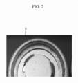
- FIG. 2 is a photograph showing corrosion occurring at a trimming part of the cylindrical battery of FIG. 1 .
- FIG. 3 is a photograph showing corrosion occurring between a gasket and a cap assembly upper surface of a cylindrical battery of FIG. 1 .
- the trimming part means an end part of the cylindrical can.
- a gasket 13 is disposed between an outer surface of a cap assembly 11 and an inner surface of a cylindrical can 12, and an upper end part of the cylindrical can 12 is processed to be bent, thereby forming a crimping structure for closing and sealing the inside of the cylindrical can 12.
- the cylindrical can 12 is manufactured by cutting a steel plate that is nickel plated on both sides to a predetermined size and processing it. Accordingly, since the trimming part A of the cylindrical can 12 is not nickel-plated, when it is exposed to external moisture, corrosion is generated like "B" of FIG. 2 (a modified position in the drawing), and if the degree of the corrosion is too severe, sealing strength of the crimping part is weakened, and there is a risk of a leakage of the electrolyte solution inside.
- the corrosion is generated like C of FIG. 3 , and when the corrosion is severe, there is a risk of leaking the electrolyte solution or changing a short-circuit pressure of the battery's CID (current interrupt device) filter.
- CID current interrupt device
- An object of the present invention is to solve the problems of the prior art and technical problems from the past.
- the inventors of the present invention having performed in-depth research and experimentation, confirmed that prevention of the corrosion may be obtained by covering a trimming part of a cylindrical can with a gasket to prevent contact with air and irradiating a laser beam between an upper surface of a cap assembly and a gasket to remove an electrolyte solution and moisture, and completed the present invention.
- the method for manufacturing a cylindrical battery according to the present invention includes: a step of housing an electrode assembly in a cylindrical can; a step of mounting the cap assembly at the top end of the electrode assembly; a step of processing the upper end part of the cylindrical can to form a crimping part; and a step of pressing the exposed part of the gasket protruded outside from a space between the cylindrical can and the cap assembly to be bent into the trimming part side of the cylindrical can.
- a pressure rod is used to press the exposed part of the gasket, and the pressure rod may include a heating member.
- the exposed part of the gasket is pressed in a state in which the cylindrical battery is rotated.
- the temperature of the pressure rod may be 100 degrees to 300 degrees Celsius.
- a step of irradiating a laser beam between the upper surface of the cap assembly and the exposed part of the gasket to remove an electrolyte solution and moisture may be further included.
- Energy of the laser beam may be in a range of 20 to 50 Joules.
- a peak output of the laser beam may have a range of 3 kilowatts to 8 kilowatts.
- a temperature range of a point where the laser beam L is irradiated may be 400 to 600 degrees Celsius.
- the word "in a cross-section” means when a cross-section taken by vertically cutting an object portion is viewed from the side.
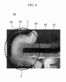
- FIG. 4 is a cross-sectional view of a crimping part of a cylindrical battery according to an exemplary embodiment of the present invention.
- the cylindrical battery 100 has an electrode assembly (not shown) housed in a cylindrical can 102.
- a cap assembly 101 is disposed with a shape covering the upper opening of the cylindrical can 102.
- a crimping part E closing and sealing the inside of the cylindrical can 102 is formed by processing the upper end part of the cylindrical can 102 to be bent.
- Part of the cap assembly 101 is disposed in a space formed inside the crimping part E.
- the gasket 103 is disposed between the cap assembly 101 and the cylindrical can 102 in the space.
- the cylindrical can 102 may be manufactured by processing a steel sheet plated with nickel on both sides.
- an exposed part 104 of the gasket 103 protruding outside from the space between the cylindrical can 102 and the cap assembly 101 is bent in the trimming part C side of the cylindrical can 102, thereby being formed of a structure covering the trimming part C while the exposed part 104 of the gasket 103 is in contact with the trimming part C.
- the trimming part C in contact with the exposed part 104 of the gasket 103 is made of steel.
- the lower end surface of the exposed part 104 of the gasket 103 may be spaced apart from the upper surface of the cap assembly 101. The method of bending the exposed part 104 of the gasket 103 is described in detail later.
- a laser beam may be irradiated between an upper surface 105 of the cap assembly 101 and the exposed part 104 of the gasket 103 to remove remaining moisture and electrolyte solution.
- the upper surface of the cap assembly 101 spaced apart from the lower end surface of the exposed part 104 of the gasket 103 may include only a metal component.
- P, F, O, Al, etc. may be detected in the remaining moisture and electrolyte solution component. The irradiation of the laser beam is described later in detail.
- the gasket 103 is a material with an electrical insulation, impact resistance, elasticity, and durability characteristics, and may be made of a polymer resin with a melting point of more than 200 degrees Celsius.
- FIG. 5 is a schematic view showing bending of an exposed part of a gasket in a cylindrical battery of FIG. 4 by using a pressure rod.
- the cylindrical battery 100 is rotated 360 degrees (referring to an arrow at a bottom of FIG. 5 ) at a constant speed.
- the rotation speed of the cylindrical battery 100 is not particularly limited, but it is preferable to maintain a range of 2 to 8 times per second.
- the exposed part 104 of the gasket 103 is pressed to the trimming part C side by the pressure rod 200.
- the exposed part 104 of the gasket 130 may be bent to cover the trimming part C by pressing.
- the material of the pressure rod 200 is not particularly limited, but it is preferable to use a pressure rod 200 made of a metal material capable of being heated, because heat must be transferred to the exposed part 104 of the gasket 103 to easily induce deformation of the exposed part 104.
- the temperature of the pressure rod 200 may be variously determined in consideration of the material of the gasket 103 and the fabrication structure of the cylindrical battery 100, but it is preferable to maintain a temperature of 100 degrees to 300 degrees Celsius. If the temperature of the pressure rod 200 is less than 100 degrees Celsius, it is not preferable because it is not easy to induce deformation of the exposed part 104 of the gasket 103. In addition, when the temperature of the pressure rod 200 exceeds 300 degrees Celsius, severe deformation occurs in the exposed part 104 of the gasket 103 and it is not easy to form the desired bending shape, and in addition, parts other than the exposed part 104 of the gasket 103 are deformed, which is not preferable because the electrolyte solution may leak by weakening the sealing force of the crimping part.
- the temperature of the pressure rod 200 in a range of higher or lower than the melting point of the gasket 103 by 20 degrees Celsius.
- the temperature of the pressure rod 200 maintains the above temperature range, it is easy to deform the exposed part 104 of the gasket 103 such that the working time may not only be shortened but also the deformation of the parts other than the exposed part 104 of the gasket 103 may be prevented.
- the method of heating the pressure rod 200 is not particularly limited, but as an example, the heating member may be heated by inserting a heating member (not shown) into the pressure rod 200 made of a metal material. It is preferable that the heating member maintains a constant temperature so that the pressure rod 200 is free of a temperature change while deforming the exposed portion 104 of the gasket 103.
- the heating member may be a heating coil connected to an external power source to generate heat.
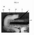
- FIG. 6 is a schematic view showing irradiation of a laser beam between a gasket of a cylindrical battery of FIG. 5 and a cap assembly.
- the corrosion occurs in the area where moisture remains, and when the corrosion is severe, as the sealing strength of the crimping part is weakened, the short pressure of a CID filter may be changed and the internal electrolyte solution of the cylindrical battery 100 may leak.
- the remaining electrolyte solution and moisture may be removed by irradiating a laser beam L.
- the laser beam L may be variously selected in consideration of the melting point of the gasket 103 and the upper surface material of the cap assembly 101, but it is preferable that the temperature range of the point where the laser beam L is irradiated is 400 to 600 degrees Celsius, and the temperature range at a part having a 0.5 millimeter radius from the point is 150 degrees to 250 degrees Celsius.
- the laser beam L is irradiated to have such a temperature range, the electrolyte solution and moisture remaining in the space D between the gasket 103 and the upper surface of the cap assembly 101 may be removed without deforming the gasket 103.
- the energy of the laser beam L has a range of 20 Joules to 50 Joules and a peak output has a range of 3 kilowatts to 8 kilowatts.
- the irradiation of the laser beam L may be performed after the step of bending the exposed part 104 of the gasket 103 as well as before it.
- the cylindrical battery according to the present invention bends the gasket protruded from the crimping part to be exposed outside in the trimming part side of the cylindrical can to enclose the trimming part, and irradiates the laser beam between the upper surface of the cap assembly and the gasket to remove the electrolyte solution and moisture, thereby preventing the corrosion.
Landscapes
- Chemical & Material Sciences (AREA)
- Chemical Kinetics & Catalysis (AREA)
- Electrochemistry (AREA)
- General Chemical & Material Sciences (AREA)
- Engineering & Computer Science (AREA)
- Physics & Mathematics (AREA)
- Optics & Photonics (AREA)
- Plasma & Fusion (AREA)
- Mechanical Engineering (AREA)
- Inorganic Chemistry (AREA)
- Sealing Battery Cases Or Jackets (AREA)
Claims (7)
- Verfahren zum Herstellen einer zylindrischen Batterie (100), umfassend:einen Schritt eines Aufnehmens einer Elektrodenanordnung in einer zylindrischen Dose (102);einen Schritt eines Montierens einer Kappenanordnung (101) an dem oberen Ende der Elektrodenanordnung;einen Schritt eines Bearbeitens des oberen Endteils der zylindrischen Dose (102), um einen Crimp-Teil (E) zu bilden; gekennzeichnet durcheinen Schritt eines Pressens eines freigelegten Teils (104) einer Dichtung (103), welcher außerhalb von einem Raum zwischen der zylindrischen Dose (102) und der Kappenanordnung (101) vorsteht, um in eine Beschnittteil (C)-Seite der zylindrischen Dose (102) gebogen zu werden,wobei eine Druckstange (200) verwendet wird, um den freigelegten Teil (104) der Dichtung (103) zu pressen, und die Druckstange (200) ein Heizelement umfasst, undwobei der freigelegte Teil (104) der Dichtung (103) in einem Zustand gepresst wird, in welchem die zylindrische Batterie (100) rotiert wird.
- Verfahren zum Herstellen der zylindrischen Batterie (100) nach Anspruch 1, wobei eine Temperatur der Druckstange (200) 100 Grad bis 300 Grad Celsius beträgt.
- Verfahren zum Herstellen der zylindrischen Batterie (100) nach Anspruch 1, ferner umfassend
einen Schritt eines Einstrahlens eines Laserstrahls (L) zwischen einer oberen Fläche der Kappenanordnung (101) und dem freigelegten Teil (104) der Dichtung (103), um eine Elektrolytlösung und Feuchtigkeit zu entfernen. - Verfahren zum Herstellen der zylindrischen Batterie (100) nach Anspruch 3, wobei Energie des Laserstrahls (L) in einem Bereich von 20 bis 50 Joule liegt.
- Verfahren zum Herstellen der zylindrischen Batterie (100) nach Anspruch 3, wobei eine Spitzenausgabe des Laserstrahls (L) in einem Bereich von 3 Kilowatt bis 8 Kilowatt liegt.
- Verfahren zum Herstellen der zylindrischen Batterie (100) nach Anspruch 3, wobei ein Temperaturbereich eines Punkts, an welchem ein Laserstrahl (L) eingestrahlt wird, 400 bis 600 Grad Celsius beträgt.
- Zylindrische Batterie (100), hergestellt mit einem Verfahren zum Herstellen der zylindrischen Batterie (100) nach wenigstens einem der Ansprüche 1 bis 6.
Applications Claiming Priority (2)
| Application Number | Priority Date | Filing Date | Title |
|---|---|---|---|
| KR1020180101584A KR102673786B1 (ko) | 2018-08-28 | 2018-08-28 | 원통형 전지 및 이의 제조 방법 |
| PCT/KR2019/010496 WO2020045873A1 (ko) | 2018-08-28 | 2019-08-19 | 원통형 전지 및 이의 제조 방법 |
Publications (3)
| Publication Number | Publication Date |
|---|---|
| EP3813142A1 EP3813142A1 (de) | 2021-04-28 |
| EP3813142A4 EP3813142A4 (de) | 2021-07-21 |
| EP3813142B1 true EP3813142B1 (de) | 2023-10-25 |
Family
ID=69644567
Family Applications (1)
| Application Number | Title | Priority Date | Filing Date |
|---|---|---|---|
| EP19855594.8A Active EP3813142B1 (de) | 2018-08-28 | 2019-08-19 | Zylinderförmige batterie und verfahren zur herstellung davon |
Country Status (8)
| Country | Link |
|---|---|
| US (1) | US12183933B2 (de) |
| EP (1) | EP3813142B1 (de) |
| KR (1) | KR102673786B1 (de) |
| CN (1) | CN112514142B (de) |
| ES (1) | ES2965685T3 (de) |
| HU (1) | HUE064675T2 (de) |
| PL (1) | PL3813142T3 (de) |
| WO (1) | WO2020045873A1 (de) |
Families Citing this family (1)
| Publication number | Priority date | Publication date | Assignee | Title |
|---|---|---|---|---|
| KR102763988B1 (ko) * | 2020-05-28 | 2025-02-07 | 주식회사 엘지에너지솔루션 | 오염물의 건식 제거 방법 |
Family Cites Families (34)
| Publication number | Priority date | Publication date | Assignee | Title |
|---|---|---|---|---|
| US4725515A (en) * | 1987-05-07 | 1988-02-16 | Eveready Battery Company | Button cell construction with internally compressed gasket |
| JP3055396B2 (ja) * | 1994-06-29 | 2000-06-26 | 松下電器産業株式会社 | 密閉形電池の製造法 |
| KR19980030967A (ko) * | 1996-10-30 | 1998-07-25 | 손욱 | 원통형 전지 및 그 제조방법 |
| KR19980057861A (ko) | 1996-12-30 | 1998-09-25 | 배순훈 | 전지 |
| JP2000030675A (ja) * | 1998-07-14 | 2000-01-28 | Hitachi Ltd | 二次電池 |
| KR20000044890A (ko) * | 1998-12-30 | 2000-07-15 | 김영환 | 반도체 소자의 플로우-필 박막을 이용한 층간 절연막형성 방법 |
| JP3811617B2 (ja) * | 2001-01-09 | 2006-08-23 | 松下電器産業株式会社 | 電池とその製造方法 |
| JP2004079355A (ja) * | 2002-08-19 | 2004-03-11 | Sony Corp | 非水電解質電池及びその製造方法 |
| JP2004220863A (ja) * | 2003-01-10 | 2004-08-05 | Sony Corp | 電池及びその製造方法 |
| KR100502446B1 (ko) * | 2003-06-16 | 2005-07-20 | 삼성에스디아이 주식회사 | 리튬 이온 2차 전지 |
| JP2005019118A (ja) * | 2003-06-25 | 2005-01-20 | Toshiba Battery Co Ltd | 筒型アルカリ電池 |
| JP2006079851A (ja) * | 2004-09-07 | 2006-03-23 | Toshiba Battery Co Ltd | 扁平形非水電解質二次電池 |
| KR100601521B1 (ko) | 2005-03-09 | 2006-07-19 | 삼성에스디아이 주식회사 | 리튬 이차전지 |
| JP4982058B2 (ja) * | 2005-08-10 | 2012-07-25 | 淀川ヒューテック株式会社 | 電池用ガスケットの製法 |
| KR100846955B1 (ko) | 2006-11-30 | 2008-07-17 | 삼성에스디아이 주식회사 | 원통형 이차전지 |
| KR100948001B1 (ko) * | 2006-12-11 | 2010-03-18 | 주식회사 엘지화학 | 안전성이 강화된 클림핑 형상의 리튬이온 이차전지 |
| KR101305461B1 (ko) * | 2007-11-08 | 2013-09-06 | 삼성에스디아이 주식회사 | 이차 전지 |
| JP5514632B2 (ja) * | 2010-05-27 | 2014-06-04 | Fdkエナジー株式会社 | 筒型電池用封口ガスケット、および筒型電池 |
| JP5480726B2 (ja) * | 2010-06-11 | 2014-04-23 | 日新製鋼株式会社 | 電池用ケースの製造方法 |
| JP5197701B2 (ja) * | 2010-09-21 | 2013-05-15 | 株式会社東芝 | 密閉型二次電池の製造装置及び製造方法 |
| KR101240717B1 (ko) * | 2010-10-13 | 2013-03-11 | 삼성에스디아이 주식회사 | 이차 전지 |
| US9070906B2 (en) * | 2011-05-26 | 2015-06-30 | Toyota Jidosha Kabushiki Kaisha | Battery assembling apparatus and battery assembly manufacturing method |
| JP5456747B2 (ja) * | 2011-10-14 | 2014-04-02 | 株式会社神戸製鋼所 | 電池ケース用アルミニウム合金板及び電池ケース |
| JP6302654B2 (ja) | 2013-12-05 | 2018-03-28 | Fdk株式会社 | 筒型電池 |
| JP6372821B2 (ja) * | 2014-01-21 | 2018-08-15 | セイコーインスツル株式会社 | 非水電解質二次電池 |
| KR20160042327A (ko) * | 2014-10-08 | 2016-04-19 | 상신이디피(주) | 원통형 이차전지 캔 및 그 제조방법 |
| KR101852250B1 (ko) * | 2015-04-02 | 2018-04-26 | 주식회사 엘지화학 | 파우치형 이차전지의 실링 장치 |
| KR20170012138A (ko) | 2015-07-23 | 2017-02-02 | 신흥에스이씨주식회사 | 이차전지용 캡조립체 및 그 이차전지 |
| KR20170085978A (ko) * | 2016-01-14 | 2017-07-25 | 신흥에스이씨주식회사 | 접촉저항성이 개선된 캡조립체 및 그 이차전지 |
| KR20180101584A (ko) | 2016-01-27 | 2018-09-12 | 브리스톨-마이어스 스큅 컴퍼니 | 항-pd-1 항체 및 또 다른 항암제의 조합을 사용하는 폐암의 치료 |
| WO2018030836A1 (en) * | 2016-08-11 | 2018-02-15 | Shin Heung Energy & Electronic Co.,Ltd. | Cap assembly for secondary battery and secondary battery including the cap assembly |
| KR102063462B1 (ko) | 2016-12-22 | 2020-01-08 | 주식회사 엘지화학 | 2차 크림핑 금형을 포함하는 원통형 전지셀 제조장치 |
| CN107706459B (zh) * | 2017-09-27 | 2023-09-26 | 珠海华冠科技股份有限公司 | 自动套管机及其垫片冲压安装装置 |
| FR3077284B1 (fr) * | 2018-01-30 | 2020-03-06 | Commissariat A L'energie Atomique Et Aux Energies Alternatives | Procede d'encapsulation d'un dispositif microelectronique, par des substrats fins ou ultrafins, facilement manipulables |
-
2018
- 2018-08-28 KR KR1020180101584A patent/KR102673786B1/ko active Active
-
2019
- 2019-08-19 US US17/264,102 patent/US12183933B2/en active Active
- 2019-08-19 ES ES19855594T patent/ES2965685T3/es active Active
- 2019-08-19 EP EP19855594.8A patent/EP3813142B1/de active Active
- 2019-08-19 CN CN201980049834.2A patent/CN112514142B/zh active Active
- 2019-08-19 WO PCT/KR2019/010496 patent/WO2020045873A1/ko not_active Ceased
- 2019-08-19 HU HUE19855594A patent/HUE064675T2/hu unknown
- 2019-08-19 PL PL19855594.8T patent/PL3813142T3/pl unknown
Also Published As
| Publication number | Publication date |
|---|---|
| WO2020045873A1 (ko) | 2020-03-05 |
| EP3813142A1 (de) | 2021-04-28 |
| HUE064675T2 (hu) | 2024-04-28 |
| EP3813142A4 (de) | 2021-07-21 |
| PL3813142T3 (pl) | 2024-02-26 |
| US12183933B2 (en) | 2024-12-31 |
| CN112514142B (zh) | 2023-03-24 |
| CN112514142A (zh) | 2021-03-16 |
| KR20200024652A (ko) | 2020-03-09 |
| ES2965685T3 (es) | 2024-04-16 |
| KR102673786B1 (ko) | 2024-06-07 |
| US20210305648A1 (en) | 2021-09-30 |
Similar Documents
| Publication | Publication Date | Title |
|---|---|---|
| KR102152143B1 (ko) | 전극판의 경계 부위에 절연 보강부가 형성된 분리막을 포함하는 전극조립체 | |
| EP4057438A1 (de) | Biegevorrichtung und -verfahren für elektrodenzungen | |
| EP3567666B1 (de) | Elektrodenanordnung | |
| JP6005173B2 (ja) | 製造工程性が向上したキャップアセンブリー及びそれを備えた円筒型電池 | |
| JP7648285B2 (ja) | 電極組立体、バッテリーセル、バッテリーパック、および自動車 | |
| EP2958177B1 (de) | Elektrodenanordnung mit abgerundeten ecken | |
| KR20130133639A (ko) | 전극 조립체, 전지셀, 전극 조립체의 제조방법 및 전지셀의 제조 방법 | |
| KR102226916B1 (ko) | 용접성이 향상된 돌기부가 형성되어 있는 원통형 이차전지 | |
| KR102108113B1 (ko) | 외주변이 절곡된 분리막을 포함하는 전극조립체 | |
| EP3813142B1 (de) | Zylinderförmige batterie und verfahren zur herstellung davon | |
| EP3399569B1 (de) | Batteriezelle mit batteriegehäuse mit unterbringungsteils und elektrodenleitungsnut | |
| JP2024521380A (ja) | 電極端子のリベット構造およびこれを含むバッテリセル、バッテリパック、並びに自動車 | |
| JP7551999B2 (ja) | 二次電池およびこれを含むデバイス | |
| EP3754778B1 (de) | Zylindrische sekundärbatterie mit einem piezoelektrischen element und einem thermoelektrischen element | |
| KR20140119499A (ko) | 이차 전지용 전극, 이를 포함하는 이차 전지, 및 이차 전지용 전극의 제조 방법 | |
| KR102010037B1 (ko) | 파우치형 이차전지를 위한 실링장치 및 파우치형 이차전지의 제작방법 | |
| KR102804460B1 (ko) | 원통형 전지 및 원통형 전지 제조 방법 | |
| KR102254262B1 (ko) | 이차전지 및 그 이차전지의 절연부재 제조 방법 | |
| US20250087822A1 (en) | Battery cell and manufacturing method of the same | |
| KR20210037460A (ko) | 이차 전지용 전지 케이스 및 그의 제조 방법 | |
| US20250329830A1 (en) | Battery cell and manufacturing method of the same | |
| KR101735805B1 (ko) | 열융착 부위가 절곡되어 있는 전지케이스를 포함하는 전지셀 | |
| KR20250037929A (ko) | 배터리셀 및 배터리셀 제조방법 | |
| KR20250157244A (ko) | 배터리 셀 및 이의 제조방법 | |
| KR20250157213A (ko) | 배터리 케이스 및 이의 제조방법 |
Legal Events
| Date | Code | Title | Description |
|---|---|---|---|
| STAA | Information on the status of an ep patent application or granted ep patent |
Free format text: STATUS: THE INTERNATIONAL PUBLICATION HAS BEEN MADE |
|
| PUAI | Public reference made under article 153(3) epc to a published international application that has entered the european phase |
Free format text: ORIGINAL CODE: 0009012 |
|
| STAA | Information on the status of an ep patent application or granted ep patent |
Free format text: STATUS: REQUEST FOR EXAMINATION WAS MADE |
|
| 17P | Request for examination filed |
Effective date: 20210125 |
|
| AK | Designated contracting states |
Kind code of ref document: A1 Designated state(s): AL AT BE BG CH CY CZ DE DK EE ES FI FR GB GR HR HU IE IS IT LI LT LU LV MC MK MT NL NO PL PT RO RS SE SI SK SM TR |
|
| AX | Request for extension of the european patent |
Extension state: BA ME |
|
| REG | Reference to a national code |
Ref country code: DE Ref legal event code: R079 Free format text: PREVIOUS MAIN CLASS: H01M0002040000 Ipc: H01M0050147000 Ref document number: 602019040275 Country of ref document: DE |
|
| A4 | Supplementary search report drawn up and despatched |
Effective date: 20210621 |
|
| RIC1 | Information provided on ipc code assigned before grant |
Ipc: H01M 50/147 20210101AFI20210615BHEP Ipc: B23K 26/36 20140101ALI20210615BHEP Ipc: B23K 101/36 20060101ALI20210615BHEP |
|
| DAV | Request for validation of the european patent (deleted) | ||
| DAX | Request for extension of the european patent (deleted) | ||
| RAP1 | Party data changed (applicant data changed or rights of an application transferred) |
Owner name: LG ENERGY SOLUTION LTD. |
|
| RAP3 | Party data changed (applicant data changed or rights of an application transferred) |
Owner name: LG ENERGY SOLUTION, LTD. |
|
| GRAP | Despatch of communication of intention to grant a patent |
Free format text: ORIGINAL CODE: EPIDOSNIGR1 |
|
| STAA | Information on the status of an ep patent application or granted ep patent |
Free format text: STATUS: GRANT OF PATENT IS INTENDED |
|
| INTG | Intention to grant announced |
Effective date: 20230523 |
|
| P01 | Opt-out of the competence of the unified patent court (upc) registered |
Effective date: 20230530 |
|
| GRAS | Grant fee paid |
Free format text: ORIGINAL CODE: EPIDOSNIGR3 |
|
| GRAA | (expected) grant |
Free format text: ORIGINAL CODE: 0009210 |
|
| STAA | Information on the status of an ep patent application or granted ep patent |
Free format text: STATUS: THE PATENT HAS BEEN GRANTED |
|
| AK | Designated contracting states |
Kind code of ref document: B1 Designated state(s): AL AT BE BG CH CY CZ DE DK EE ES FI FR GB GR HR HU IE IS IT LI LT LU LV MC MK MT NL NO PL PT RO RS SE SI SK SM TR |
|
| REG | Reference to a national code |
Ref country code: GB Ref legal event code: FG4D |
|
| REG | Reference to a national code |
Ref country code: CH Ref legal event code: EP |
|
| REG | Reference to a national code |
Ref country code: DE Ref legal event code: R096 Ref document number: 602019040275 Country of ref document: DE |
|
| REG | Reference to a national code |
Ref country code: IE Ref legal event code: FG4D |
|
| REG | Reference to a national code |
Ref country code: NL Ref legal event code: FP |
|
| REG | Reference to a national code |
Ref country code: SE Ref legal event code: TRGR |
|
| REG | Reference to a national code |
Ref country code: LT Ref legal event code: MG9D |
|
| REG | Reference to a national code |
Ref country code: AT Ref legal event code: MK05 Ref document number: 1625608 Country of ref document: AT Kind code of ref document: T Effective date: 20231025 |
|
| PG25 | Lapsed in a contracting state [announced via postgrant information from national office to epo] |
Ref country code: GR Free format text: LAPSE BECAUSE OF FAILURE TO SUBMIT A TRANSLATION OF THE DESCRIPTION OR TO PAY THE FEE WITHIN THE PRESCRIBED TIME-LIMIT Effective date: 20240126 |
|
| PG25 | Lapsed in a contracting state [announced via postgrant information from national office to epo] |
Ref country code: IS Free format text: LAPSE BECAUSE OF FAILURE TO SUBMIT A TRANSLATION OF THE DESCRIPTION OR TO PAY THE FEE WITHIN THE PRESCRIBED TIME-LIMIT Effective date: 20240225 |
|
| PG25 | Lapsed in a contracting state [announced via postgrant information from national office to epo] |
Ref country code: LT Free format text: LAPSE BECAUSE OF FAILURE TO SUBMIT A TRANSLATION OF THE DESCRIPTION OR TO PAY THE FEE WITHIN THE PRESCRIBED TIME-LIMIT Effective date: 20231025 |
|
| REG | Reference to a national code |
Ref country code: ES Ref legal event code: FG2A Ref document number: 2965685 Country of ref document: ES Kind code of ref document: T3 Effective date: 20240416 |
|
| PG25 | Lapsed in a contracting state [announced via postgrant information from national office to epo] |
Ref country code: AT Free format text: LAPSE BECAUSE OF FAILURE TO SUBMIT A TRANSLATION OF THE DESCRIPTION OR TO PAY THE FEE WITHIN THE PRESCRIBED TIME-LIMIT Effective date: 20231025 |
|
| REG | Reference to a national code |
Ref country code: HU Ref legal event code: AG4A Ref document number: E064675 Country of ref document: HU |
|
| PG25 | Lapsed in a contracting state [announced via postgrant information from national office to epo] |
Ref country code: LT Free format text: LAPSE BECAUSE OF FAILURE TO SUBMIT A TRANSLATION OF THE DESCRIPTION OR TO PAY THE FEE WITHIN THE PRESCRIBED TIME-LIMIT Effective date: 20231025 Ref country code: IS Free format text: LAPSE BECAUSE OF FAILURE TO SUBMIT A TRANSLATION OF THE DESCRIPTION OR TO PAY THE FEE WITHIN THE PRESCRIBED TIME-LIMIT Effective date: 20240225 Ref country code: GR Free format text: LAPSE BECAUSE OF FAILURE TO SUBMIT A TRANSLATION OF THE DESCRIPTION OR TO PAY THE FEE WITHIN THE PRESCRIBED TIME-LIMIT Effective date: 20240126 Ref country code: BG Free format text: LAPSE BECAUSE OF FAILURE TO SUBMIT A TRANSLATION OF THE DESCRIPTION OR TO PAY THE FEE WITHIN THE PRESCRIBED TIME-LIMIT Effective date: 20240125 Ref country code: AT Free format text: LAPSE BECAUSE OF FAILURE TO SUBMIT A TRANSLATION OF THE DESCRIPTION OR TO PAY THE FEE WITHIN THE PRESCRIBED TIME-LIMIT Effective date: 20231025 Ref country code: PT Free format text: LAPSE BECAUSE OF FAILURE TO SUBMIT A TRANSLATION OF THE DESCRIPTION OR TO PAY THE FEE WITHIN THE PRESCRIBED TIME-LIMIT Effective date: 20240226 |
|
| PG25 | Lapsed in a contracting state [announced via postgrant information from national office to epo] |
Ref country code: RS Free format text: LAPSE BECAUSE OF FAILURE TO SUBMIT A TRANSLATION OF THE DESCRIPTION OR TO PAY THE FEE WITHIN THE PRESCRIBED TIME-LIMIT Effective date: 20231025 Ref country code: NO Free format text: LAPSE BECAUSE OF FAILURE TO SUBMIT A TRANSLATION OF THE DESCRIPTION OR TO PAY THE FEE WITHIN THE PRESCRIBED TIME-LIMIT Effective date: 20240125 Ref country code: LV Free format text: LAPSE BECAUSE OF FAILURE TO SUBMIT A TRANSLATION OF THE DESCRIPTION OR TO PAY THE FEE WITHIN THE PRESCRIBED TIME-LIMIT Effective date: 20231025 Ref country code: HR Free format text: LAPSE BECAUSE OF FAILURE TO SUBMIT A TRANSLATION OF THE DESCRIPTION OR TO PAY THE FEE WITHIN THE PRESCRIBED TIME-LIMIT Effective date: 20231025 |
|
| PG25 | Lapsed in a contracting state [announced via postgrant information from national office to epo] |
Ref country code: DK Free format text: LAPSE BECAUSE OF FAILURE TO SUBMIT A TRANSLATION OF THE DESCRIPTION OR TO PAY THE FEE WITHIN THE PRESCRIBED TIME-LIMIT Effective date: 20231025 |
|
| PG25 | Lapsed in a contracting state [announced via postgrant information from national office to epo] |
Ref country code: CZ Free format text: LAPSE BECAUSE OF FAILURE TO SUBMIT A TRANSLATION OF THE DESCRIPTION OR TO PAY THE FEE WITHIN THE PRESCRIBED TIME-LIMIT Effective date: 20231025 |
|
| REG | Reference to a national code |
Ref country code: DE Ref legal event code: R097 Ref document number: 602019040275 Country of ref document: DE |
|
| PG25 | Lapsed in a contracting state [announced via postgrant information from national office to epo] |
Ref country code: SK Free format text: LAPSE BECAUSE OF FAILURE TO SUBMIT A TRANSLATION OF THE DESCRIPTION OR TO PAY THE FEE WITHIN THE PRESCRIBED TIME-LIMIT Effective date: 20231025 |
|
| PG25 | Lapsed in a contracting state [announced via postgrant information from national office to epo] |
Ref country code: SM Free format text: LAPSE BECAUSE OF FAILURE TO SUBMIT A TRANSLATION OF THE DESCRIPTION OR TO PAY THE FEE WITHIN THE PRESCRIBED TIME-LIMIT Effective date: 20231025 Ref country code: SK Free format text: LAPSE BECAUSE OF FAILURE TO SUBMIT A TRANSLATION OF THE DESCRIPTION OR TO PAY THE FEE WITHIN THE PRESCRIBED TIME-LIMIT Effective date: 20231025 Ref country code: RO Free format text: LAPSE BECAUSE OF FAILURE TO SUBMIT A TRANSLATION OF THE DESCRIPTION OR TO PAY THE FEE WITHIN THE PRESCRIBED TIME-LIMIT Effective date: 20231025 Ref country code: EE Free format text: LAPSE BECAUSE OF FAILURE TO SUBMIT A TRANSLATION OF THE DESCRIPTION OR TO PAY THE FEE WITHIN THE PRESCRIBED TIME-LIMIT Effective date: 20231025 Ref country code: DK Free format text: LAPSE BECAUSE OF FAILURE TO SUBMIT A TRANSLATION OF THE DESCRIPTION OR TO PAY THE FEE WITHIN THE PRESCRIBED TIME-LIMIT Effective date: 20231025 Ref country code: CZ Free format text: LAPSE BECAUSE OF FAILURE TO SUBMIT A TRANSLATION OF THE DESCRIPTION OR TO PAY THE FEE WITHIN THE PRESCRIBED TIME-LIMIT Effective date: 20231025 |
|
| PLBE | No opposition filed within time limit |
Free format text: ORIGINAL CODE: 0009261 |
|
| STAA | Information on the status of an ep patent application or granted ep patent |
Free format text: STATUS: NO OPPOSITION FILED WITHIN TIME LIMIT |
|
| 26N | No opposition filed |
Effective date: 20240726 |
|
| PG25 | Lapsed in a contracting state [announced via postgrant information from national office to epo] |
Ref country code: SI Free format text: LAPSE BECAUSE OF FAILURE TO SUBMIT A TRANSLATION OF THE DESCRIPTION OR TO PAY THE FEE WITHIN THE PRESCRIBED TIME-LIMIT Effective date: 20231025 |
|
| PG25 | Lapsed in a contracting state [announced via postgrant information from national office to epo] |
Ref country code: SI Free format text: LAPSE BECAUSE OF FAILURE TO SUBMIT A TRANSLATION OF THE DESCRIPTION OR TO PAY THE FEE WITHIN THE PRESCRIBED TIME-LIMIT Effective date: 20231025 |
|
| REG | Reference to a national code |
Ref country code: CH Ref legal event code: PL |
|
| PG25 | Lapsed in a contracting state [announced via postgrant information from national office to epo] |
Ref country code: LU Free format text: LAPSE BECAUSE OF NON-PAYMENT OF DUE FEES Effective date: 20240819 |
|
| PG25 | Lapsed in a contracting state [announced via postgrant information from national office to epo] |
Ref country code: CH Free format text: LAPSE BECAUSE OF NON-PAYMENT OF DUE FEES Effective date: 20240831 Ref country code: MC Free format text: LAPSE BECAUSE OF FAILURE TO SUBMIT A TRANSLATION OF THE DESCRIPTION OR TO PAY THE FEE WITHIN THE PRESCRIBED TIME-LIMIT Effective date: 20231025 |
|
| REG | Reference to a national code |
Ref country code: BE Ref legal event code: MM Effective date: 20240831 |
|
| PG25 | Lapsed in a contracting state [announced via postgrant information from national office to epo] |
Ref country code: BE Free format text: LAPSE BECAUSE OF NON-PAYMENT OF DUE FEES Effective date: 20240831 |
|
| PG25 | Lapsed in a contracting state [announced via postgrant information from national office to epo] |
Ref country code: IE Free format text: LAPSE BECAUSE OF NON-PAYMENT OF DUE FEES Effective date: 20240819 |
|
| PGFP | Annual fee paid to national office [announced via postgrant information from national office to epo] |
Ref country code: NL Payment date: 20250722 Year of fee payment: 7 |
|
| PGFP | Annual fee paid to national office [announced via postgrant information from national office to epo] |
Ref country code: HU Payment date: 20250827 Year of fee payment: 7 |
|
| PG25 | Lapsed in a contracting state [announced via postgrant information from national office to epo] |
Ref country code: FI Free format text: LAPSE BECAUSE OF FAILURE TO SUBMIT A TRANSLATION OF THE DESCRIPTION OR TO PAY THE FEE WITHIN THE PRESCRIBED TIME-LIMIT Effective date: 20231025 |
|
| PGFP | Annual fee paid to national office [announced via postgrant information from national office to epo] |
Ref country code: ES Payment date: 20250911 Year of fee payment: 7 |
|
| PGFP | Annual fee paid to national office [announced via postgrant information from national office to epo] |
Ref country code: DE Payment date: 20250721 Year of fee payment: 7 |
|
| PGFP | Annual fee paid to national office [announced via postgrant information from national office to epo] |
Ref country code: PL Payment date: 20250723 Year of fee payment: 7 Ref country code: TR Payment date: 20250723 Year of fee payment: 7 Ref country code: IT Payment date: 20250722 Year of fee payment: 7 |
|
| PGFP | Annual fee paid to national office [announced via postgrant information from national office to epo] |
Ref country code: GB Payment date: 20250722 Year of fee payment: 7 |
|
| PGFP | Annual fee paid to national office [announced via postgrant information from national office to epo] |
Ref country code: FR Payment date: 20250725 Year of fee payment: 7 |
|
| PGFP | Annual fee paid to national office [announced via postgrant information from national office to epo] |
Ref country code: SE Payment date: 20250722 Year of fee payment: 7 |
|
| PG25 | Lapsed in a contracting state [announced via postgrant information from national office to epo] |
Ref country code: CY Free format text: LAPSE BECAUSE OF FAILURE TO SUBMIT A TRANSLATION OF THE DESCRIPTION OR TO PAY THE FEE WITHIN THE PRESCRIBED TIME-LIMIT; INVALID AB INITIO Effective date: 20190819 |