EP3754778B1 - Zylindrische sekundärbatterie mit einem piezoelektrischen element und einem thermoelektrischen element - Google Patents
Zylindrische sekundärbatterie mit einem piezoelektrischen element und einem thermoelektrischen element Download PDFInfo
- Publication number
- EP3754778B1 EP3754778B1 EP19888362.1A EP19888362A EP3754778B1 EP 3754778 B1 EP3754778 B1 EP 3754778B1 EP 19888362 A EP19888362 A EP 19888362A EP 3754778 B1 EP3754778 B1 EP 3754778B1
- Authority
- EP
- European Patent Office
- Prior art keywords
- positive electrode
- electrode tab
- thermoelectric element
- piezoelectric element
- rechargeable battery
- Prior art date
- Legal status (The legal status is an assumption and is not a legal conclusion. Google has not performed a legal analysis and makes no representation as to the accuracy of the status listed.)
- Active
Links
Images


Classifications
-
- H—ELECTRICITY
- H01—ELECTRIC ELEMENTS
- H01M—PROCESSES OR MEANS, e.g. BATTERIES, FOR THE DIRECT CONVERSION OF CHEMICAL ENERGY INTO ELECTRICAL ENERGY
- H01M10/00—Secondary cells; Manufacture thereof
- H01M10/60—Heating or cooling; Temperature control
- H01M10/61—Types of temperature control
- H01M10/613—Cooling or keeping cold
-
- H—ELECTRICITY
- H01—ELECTRIC ELEMENTS
- H01M—PROCESSES OR MEANS, e.g. BATTERIES, FOR THE DIRECT CONVERSION OF CHEMICAL ENERGY INTO ELECTRICAL ENERGY
- H01M10/00—Secondary cells; Manufacture thereof
- H01M10/60—Heating or cooling; Temperature control
- H01M10/64—Heating or cooling; Temperature control characterised by the shape of the cells
- H01M10/643—Cylindrical cells
-
- H—ELECTRICITY
- H01—ELECTRIC ELEMENTS
- H01M—PROCESSES OR MEANS, e.g. BATTERIES, FOR THE DIRECT CONVERSION OF CHEMICAL ENERGY INTO ELECTRICAL ENERGY
- H01M10/00—Secondary cells; Manufacture thereof
- H01M10/60—Heating or cooling; Temperature control
- H01M10/65—Means for temperature control structurally associated with the cells
- H01M10/655—Solid structures for heat exchange or heat conduction
- H01M10/6553—Terminals or leads
-
- H—ELECTRICITY
- H01—ELECTRIC ELEMENTS
- H01M—PROCESSES OR MEANS, e.g. BATTERIES, FOR THE DIRECT CONVERSION OF CHEMICAL ENERGY INTO ELECTRICAL ENERGY
- H01M10/00—Secondary cells; Manufacture thereof
- H01M10/60—Heating or cooling; Temperature control
- H01M10/65—Means for temperature control structurally associated with the cells
- H01M10/657—Means for temperature control structurally associated with the cells by electric or electromagnetic means
- H01M10/6572—Peltier elements or thermoelectric devices
-
- H—ELECTRICITY
- H01—ELECTRIC ELEMENTS
- H01M—PROCESSES OR MEANS, e.g. BATTERIES, FOR THE DIRECT CONVERSION OF CHEMICAL ENERGY INTO ELECTRICAL ENERGY
- H01M50/00—Constructional details or processes of manufacture of the non-active parts of electrochemical cells other than fuel cells, e.g. hybrid cells
- H01M50/50—Current conducting connections for cells or batteries
- H01M50/531—Electrode connections inside a battery casing
- H01M50/533—Electrode connections inside a battery casing characterised by the shape of the leads or tabs
-
- H—ELECTRICITY
- H01—ELECTRIC ELEMENTS
- H01M—PROCESSES OR MEANS, e.g. BATTERIES, FOR THE DIRECT CONVERSION OF CHEMICAL ENERGY INTO ELECTRICAL ENERGY
- H01M10/00—Secondary cells; Manufacture thereof
- H01M10/04—Construction or manufacture in general
- H01M10/0422—Cells or battery with cylindrical casing
-
- H—ELECTRICITY
- H01—ELECTRIC ELEMENTS
- H01M—PROCESSES OR MEANS, e.g. BATTERIES, FOR THE DIRECT CONVERSION OF CHEMICAL ENERGY INTO ELECTRICAL ENERGY
- H01M10/00—Secondary cells; Manufacture thereof
- H01M10/05—Accumulators with non-aqueous electrolyte
- H01M10/052—Li-accumulators
-
- H—ELECTRICITY
- H01—ELECTRIC ELEMENTS
- H01M—PROCESSES OR MEANS, e.g. BATTERIES, FOR THE DIRECT CONVERSION OF CHEMICAL ENERGY INTO ELECTRICAL ENERGY
- H01M10/00—Secondary cells; Manufacture thereof
- H01M10/05—Accumulators with non-aqueous electrolyte
- H01M10/052—Li-accumulators
- H01M10/0525—Rocking-chair batteries, i.e. batteries with lithium insertion or intercalation in both electrodes; Lithium-ion batteries
-
- Y—GENERAL TAGGING OF NEW TECHNOLOGICAL DEVELOPMENTS; GENERAL TAGGING OF CROSS-SECTIONAL TECHNOLOGIES SPANNING OVER SEVERAL SECTIONS OF THE IPC; TECHNICAL SUBJECTS COVERED BY FORMER USPC CROSS-REFERENCE ART COLLECTIONS [XRACs] AND DIGESTS
- Y02—TECHNOLOGIES OR APPLICATIONS FOR MITIGATION OR ADAPTATION AGAINST CLIMATE CHANGE
- Y02E—REDUCTION OF GREENHOUSE GAS [GHG] EMISSIONS, RELATED TO ENERGY GENERATION, TRANSMISSION OR DISTRIBUTION
- Y02E60/00—Enabling technologies; Technologies with a potential or indirect contribution to GHG emissions mitigation
- Y02E60/10—Energy storage using batteries
Definitions
- the present invention relates to a cylindrical rechargeable battery including a piezoelectric element and a thermoelectric element.
- lithium rechargeable batteries such as lithium ion batteries, lithium ion polymer batteries, and the like which have advantages such as high energy density, discharge voltage, and output stability.
- Such rechargeable batteries are classified depending on a structure of an electrode assembly in which a positive electrode, a negative electrode, and a separator interposed between the positive electrode and the negative electrode are stacked.
- Representative examples thereof may include a jelly-roll type (wound-type) of electrode assembly in which a positive electrode and a negative electrode having a long sheet-like shape are wound with a separator interposed therebetween, a stacked type of electrode assembly in which a plurality of positive electrodes and negative electrodes that are cut in a predetermined size unit are sequentially stacked with separators interposed therebetween, and the like.
- a stack/folding type of electrode assembly in which unit cells obtained by stacking positive and negative electrodes of a predetermined unit with separators interposed therebetween, which are disposed on a separation film, are sequentially wound has been developed as an electrode assembly having an advanced structure in which the jelly-roll type and the stack type are mixed in order to solve problems of the jelly-roll types and the stack types of electrode assemblies.
- Such electrode assemblies are accommodated in a pouch case, a cylindrical can, a rectangular case, or the like depending on the purpose of use, to manufacture batteries.
- the cylindrical battery has the advantages of easy manufacturing and high energy density per unit weight, and is used as an energy source of various devices ranging from portable computers to battery cars.
- a content of silicon is increased in a negative electrode active material in order to maximize a high energy density advantage.
- silicon has large volume expansion during charge and discharge of the battery, which causes a lot of stress in the battery during repeated volume expansion of the negative electrode.
- Graphite has a relatively small volume expansion compared to silicon, but it also causes volume expansion and stress. In particular, there is a problem that the stress is concentrated in a stepped portion of the two electrodes.
- KR 20200028712 A which is a document published later than the priority date of this application, discloses a thermoelectric element which is integrated in a tab of a cylindrical battery, and a piezoelectric element is integrated in a cap of the battery.
- KR 20180054077 A discloses a lithium secondary battery with a rubber member comprising a PTC device.
- the PTC device is capable of shutting off the battery when the internal temperature is between 120°C and 170°C.
- An object of the present invention is to solve the problems of the prior art and technical problems from the past.
- the inventors of the present application confirmed that a stress generated by the expansion of the negative electrode may be converted into electrical energy to control thermal energy using the electrical energy, by installing a piezoelectric element and a thermoelectric element in the positive electrode tab, thereby completing the present invention.
- a cylindrical rechargeable battery according to the present invention for achieving this purpose includes a positive electrode, a negative electrode, and a separator, the positive electrode includes a positive electrode tab, and a piezoelectric element and a thermoelectric element are formed at edges of the positive electrode tab.
- the positive electrode tab may have a rectangular strip shape having a long length in comparison with a width.
- the piezoelectric element and the thermoelectric element may be formed at opposite edges of the positive electrode tab in a longitudinal direction thereof.
- Accommodating spaces in which the piezoelectric element and the thermoelectric element are mounted may be formed at the edges.
- the accommodating spaces may have a stepped shape.
- Only the piezoelectric element may be formed at the edges.
- thermoelectric element may be formed at a central portion of the positive electrode tab.
- An indentation may be formed to have a structure indented into the positive electrode tab.
- thermoelectric element may be accommodated in the indentation.
- the electrical energy generated by the piezoelectric element may be transferred to the thermoelectric element through the positive electrode tab.
- Two or more of the positive electrode tabs may be formed in the positive electrode.
- the negative electrode is manufactured by applying and drying a negative electrode active material on a negative electrode current collector, and optionally, additional components may be further included.
- the negative electrode collector is typically formed to have a thickness of 3 to 500 ⁇ m.
- a negative electrode current collector is not particularly limited as long as it has conductivity without causing chemical change in the battery, and for example, copper, stainless steel, aluminum, nickel, titanium, calcined carbon, or copper or stainless steel, a surface of which is treated with the carbon, nickel, titanium, silver, aluminum-cadmium alloy, or the like, may be used.
- fine concavities and convexities may be formed on a surface of the negative electrode current collector to enhance the bonding strength of the negative electrode active material, and it may be used in various forms such as a film, a sheet, a foil, a net, a porous body, a foam, and a nonwoven fabric.
- carbon such as hardly graphitized carbon and graphite-type carbon
- a metal composite oxide such as Li x Fe 2 O 3 (0 ⁇ x ⁇ 1), Li x WO 2 (0 ⁇ x ⁇ 1), Sn x Me 1-x Me' y O z (Me: Mn, Fe, Pb, and Ge; Me': Al, B, P, Si, Group 1, Group 2, and Group 3 elements of the periodic table, and halogen; 0 ⁇ x ⁇ 1; 1 ⁇ y ⁇ 3; 1 ⁇ z ⁇ 8)
- a lithium metal such as SnO, SnO 2 , PbO, PbO 2 , Pb 2 O 3 , Pb 3 O 4 , Sb 2 O 3 , Sb 2 O 4 , Sb 2 O 5 , GeO, GeO 2 , Bi 2 O 3 , Bi 2 O 4 , and Bi 2 O 5
- a conductive polymer such as polyacet
- the negative electrode active material may contain 25 % or less of silicon.
- the negative electrode may include a negative electrode tab, and the piezoelectric element and the thermoelectric element may be formed at edges of the negative electrode tab.
- cross-section when referred to as "cross-section", it indicates when a cross-section which cuts a target part vertically is seen from the side.
- top view when referred to as “top view”, it indicates when a target portion is viewed from above.
- FIG. 1 illustrates a plan view of a cylindrical rechargeable battery in which a piezoelectric element and a thermoelectric element are formed at a positive electrode tab thereof according to an exemplary embodiment of the present invention.
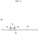
- FIG. 2 illustrates a cross-sectional view taken along a dotted line C of FIG. 1 .
- FIG. 1 illustrates an enlarged view of a portion where the positive electrode tab 101 is formed at an uncoated portion 104 of a positive electrode 105 before the positive electrode 105 and a negative electrode (not illustrated) are wound with the separator interposed therebetween.
- the positive electrode tab 101 may have a rectangular strip shape having a long length in comparison with a width.
- the piezoelectric element 102 and the thermoelectric element 103 may be formed at opposite edges A and B in a longitudinal direction. As described above, the edges A and B are portions where stresses generated by repeated expansion of the negative electrode (not illustrated) are concentrated during charging and discharging of the cylindrical rechargeable battery 100. This stress may be converted into battery energy through the piezoelectric element 102.
- the battery energy operates the thermoelectric element 103 to absorb thermal energy generated in the cylindrical rechargeable battery 100 during the charge and discharge process. The electrical energy produced by the piezoelectric element 102 may be transferred to the thermoelectric element 103 through various paths.
- the electrical energy may be transferred through a metal connector (not illustrated) electrically connecting to the piezoelectric element 102 and the thermoelectric element 103.
- the electrical energy generated by the piezoelectric element 102 is transferred to the thermoelectric element 103 through the positive electrode tab 101.
- a portion where the positive electrode tab 101 is formed is a portion where a lot of thermal energy is intensively generated by a rapid flow of current in the charging and discharging process of the cylindrical rechargeable battery 100. This thermal energy is absorbed and controlled by the thermoelectric element 103.
- FIG. 3 illustrates a top plan view according to another exemplary embodiment of the present invention.
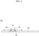
- FIG. 4 illustrates a cross-sectional view taken along a dotted line C of FIG. 3 .
- FIG. 5 illustrates a cross-sectional view of an electrode tab taken along the dotted line C of FIG. 3 .
- accommodating spaces 110 and 120 in which the piezoelectric element 102 and the thermoelectric element 103 are mounted are formed at opposite edges A and B of the positive electrode tab 101 of a cylindrical rechargeable battery 200.
- a form of the accommodating spaces 110 and 120 is not particularly limited, but as an example, it may be formed in the form of a step.
- An entire part or a portion of the piezoelectric element 102 is formed in the accommodating space 110 of the edge A.
- An entire part or a portion of the thermoelectric element 103 is formed in the accommodating space 120 of the edge B.
- the piezoelectric element 102 and the thermoelectric element 103 of various shapes and volumes may be applied to the positive electrode tab 101, and the piezoelectric element 102 and the thermoelectric element 103 may be prevented from escaping from the positive electrode tab 101 by a stress generated in a direction D during the charge and discharge process.
- the direction D indicates a direction perpendicular to a longitudinal direction of the positive electrode tab 101 in a direction parallel to a surface where the positive electrode 105 is formed with respect to the ground.
- FIG. 6 illustrates a top plan view according to another exemplary embodiment of the present invention.
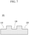
- FIG. 7 illustrates a cross-sectional view of an electrode tab taken along the dotted line C of FIG. 6 .
- the piezoelectric element 102 is formed at edges A and B of the positive electrode tab 101 of a cylindrical rechargeable battery 300, and the thermoelectric element 103 is formed at a central portion of the positive electrode tab 101.
- edges A and B are portions where stresses generated by repeated expansion of the negative electrode (not illustrated) are concentrated during charging and discharging of the cylindrical rechargeable battery 300. Therefore, only the piezoelectric element 102 is installed at the edges A and B to secure more battery energy. In addition, it is possible to easily control the high thermal energy generated in the cylindrical rechargeable battery 300 of high capacity and high output by operating the thermoelectric element 103 with the battery energy.
- the accommodating spaces 110 and 120 in which the piezoelectric element 102 is mounted are formed at opposite edges A and B of the positive electrode tab 101.
- a form of the accommodating spaces 110 and 120 is not particularly limited, but as an example, they may be formed in the form of a step. An entire part or a portion of the piezoelectric element 102 may be formed in the accommodating spaces 110 and 120 of the edges A and B.
- thermoelectric element 103 in which the thermoelectric element 103 is accommodatable may be formed in a central portion of the positive electrode tab 101.
- the indentation 130 may be formed to have a structure indented into the positive electrode tab 101, and an entire part or a portion of the thermoelectric element 103 may be accommodated in the indentation 130.
- the thermoelectric element 103 of various shapes and volumes may be applied to the positive electrode tab 101.
- an area in which the thermoelectric element 103 contacts the positive electrode tab 101 may be maximized so that thermal energy generated in the positive electrode tab 101 may be quickly transferred to the thermoelectric element 103 to be cooled.
- the piezoelectric element 102 and the thermoelectric element 103 described above may be equally applied to the negative electrode tab (not illustrated).
- the piezoelectric element and the thermoelectric element are formed on the positive electrode tab, thereby changing the stress generated during the expansion of the negative electrode to electrical energy using the piezoelectric element, and the electrical energy may be used to operate the thermoelectric element to thereby control the thermal energy issued inside the battery.
Landscapes
- Chemical & Material Sciences (AREA)
- Chemical Kinetics & Catalysis (AREA)
- Electrochemistry (AREA)
- General Chemical & Material Sciences (AREA)
- Engineering & Computer Science (AREA)
- Manufacturing & Machinery (AREA)
- Physics & Mathematics (AREA)
- Electromagnetism (AREA)
- Secondary Cells (AREA)
- Connection Of Batteries Or Terminals (AREA)
- Battery Electrode And Active Subsutance (AREA)
Claims (11)
- Zylindrische wiederaufladbare Batterie (100), umfassend:
eine positive Elektrode (105), eine negative Elektrode und einen Separator, wobei die positive Elektrode (105) eine positive Elektrodenlasche (101) beinhaltet und ein piezoelektrisches Element (102) und ein thermoelektrisches Element (103) an Kanten (A, B) der positiven Elektrodenlasche (101) ausgebildet sind. - Zylindrische wiederaufladbare Batterie (100) nach Anspruch 1, wobei
die positive Elektrodenlasche (101) eine rechteckige Streifenform mit einer im Vergleich zu einer Breite großen Länge aufweist. - Zylindrische wiederaufladbare Batterie (100) nach Anspruch 2, wobei
das piezoelektrische Element (102) und das thermoelektrische Element (103) an gegenüberliegenden Kanten (A, B) der positiven Elektrodenlasche (101) in deren Längsrichtung ausgebildet sind. - Zylindrische wiederaufladbare Batterie (100) nach Anspruch 1, wobei
Aufnahmeräume (110, 120), in denen das piezoelektrische Element (102) und das thermoelektrische Element (103) angebracht sind, an den Kanten (A, B) ausgebildet sind. - Zylindrische wiederaufladbare Batterie (100) nach Anspruch 4, wobei die Aufnahmeräume (110, 120) eine gestufte Form aufweisen.
- Zylindrische wiederaufladbare Batterie (100) nach Anspruch 1, wobei das piezoelektrische Element (102) an den Kanten (A, B) ausgebildet ist.
- Zylindrische wiederaufladbare Batterie (300) nach Anspruch 6, wobei
das thermoelektrische Element (103) an einem zentralen Abschnitt der positiven Elektrodenlasche (101) ausgebildet ist. - Zylindrische wiederaufladbare Batterie (100) nach Anspruch 7, wobei
eine Vertiefung (130) so ausgebildet ist, dass sie eine in die positive Elektrodenlasche (101) eingebuchtete Struktur aufweist. - Zylindrische, wiederaufladbare Batterie (300) nach Anspruch 8, wobei
das thermoelektrische Element (103) in der Vertiefung (130) untergebracht ist. - Zylindrische wiederaufladbare Batterie (100) nach Anspruch 1, wobei
elektrische Energie, die von dem piezoelektrischen Element (102) erzeugt wird, durch die positive Elektrodenlasche (101) auf das thermoelektrische Element (103) übertragen wird. - Zylindrische wiederaufladbare Batterie (100) nach Anspruch 1, wobei
die negative Elektrode eine negative Elektrodenlasche beinhaltet und das piezoelektrische Element und das thermoelektrische Element an Kanten der negativen Elektrodenlasche ausgebildet sind.
Applications Claiming Priority (2)
| Application Number | Priority Date | Filing Date | Title |
|---|---|---|---|
| KR1020180152912A KR102398572B1 (ko) | 2018-11-30 | 2018-11-30 | 압전 소자 및 열전 소자를 포함하는 원통형 이차 전지 |
| PCT/KR2019/015460 WO2020111595A1 (ko) | 2018-11-30 | 2019-11-13 | 압전 소자 및 열전 소자를 포함하는 원통형 이차 전지 |
Publications (3)
| Publication Number | Publication Date |
|---|---|
| EP3754778A1 EP3754778A1 (de) | 2020-12-23 |
| EP3754778A4 EP3754778A4 (de) | 2021-05-26 |
| EP3754778B1 true EP3754778B1 (de) | 2025-01-01 |
Family
ID=70854092
Family Applications (1)
| Application Number | Title | Priority Date | Filing Date |
|---|---|---|---|
| EP19888362.1A Active EP3754778B1 (de) | 2018-11-30 | 2019-11-13 | Zylindrische sekundärbatterie mit einem piezoelektrischen element und einem thermoelektrischen element |
Country Status (9)
| Country | Link |
|---|---|
| US (1) | US11450906B2 (de) |
| EP (1) | EP3754778B1 (de) |
| JP (1) | JP7463652B2 (de) |
| KR (1) | KR102398572B1 (de) |
| CN (1) | CN111937225B (de) |
| ES (1) | ES3009545T3 (de) |
| HU (1) | HUE070103T2 (de) |
| PL (1) | PL3754778T3 (de) |
| WO (1) | WO2020111595A1 (de) |
Families Citing this family (2)
| Publication number | Priority date | Publication date | Assignee | Title |
|---|---|---|---|---|
| KR102842611B1 (ko) * | 2020-10-27 | 2025-08-04 | 에스케이온 주식회사 | 이차 전지 |
| JPWO2023181853A1 (de) * | 2022-03-25 | 2023-09-28 |
Citations (2)
| Publication number | Priority date | Publication date | Assignee | Title |
|---|---|---|---|---|
| US20120114979A1 (en) * | 2009-08-14 | 2012-05-10 | Lg Chem, Ltd. | Cylindrical secondary battery of improved safety |
| US20160197379A1 (en) * | 2015-01-07 | 2016-07-07 | Samsung Sdi Co., Ltd. | Secondary battery |
Family Cites Families (25)
| Publication number | Priority date | Publication date | Assignee | Title |
|---|---|---|---|---|
| US5188286A (en) * | 1991-12-18 | 1993-02-23 | International Business Machines Corporation | Thermoelectric piezoelectric temperature control |
| US5378551A (en) | 1993-07-19 | 1995-01-03 | Motorola, Inc. | Rechargeable battery cell having integral vibrating means |
| CN1464566A (zh) * | 2002-06-13 | 2003-12-31 | 王正峰 | 环境噪能电池 |
| JP2005209395A (ja) | 2004-01-20 | 2005-08-04 | Toshiba Corp | 非水電解液二次電池 |
| JP3983755B2 (ja) * | 2004-09-30 | 2007-09-26 | 三菱電機株式会社 | ノックセンサ |
| KR100808380B1 (ko) * | 2004-10-14 | 2008-02-29 | 주식회사 엘지화학 | 전지단자에 안전소자가 구비된 이차전지 |
| KR100878702B1 (ko) * | 2005-11-30 | 2009-01-14 | 주식회사 엘지화학 | 이차전지용 안전장치 및 그것을 포함하는 전지팩 |
| EP1999805B1 (de) * | 2006-03-30 | 2014-08-06 | Lg Chem, Ltd. | Sekundärbatterie verbesserter sicherheit |
| KR101029020B1 (ko) | 2006-11-27 | 2011-04-14 | 주식회사 엘지화학 | 도전성 부재들의 전기적 연결 방법 |
| KR20110015070A (ko) * | 2009-08-07 | 2011-02-15 | 주식회사 엘지화학 | 외부단락 안전성 확보용 배터리 |
| US9035497B2 (en) | 2009-09-30 | 2015-05-19 | University Of Florida Research Foundation, Inc. | Method and apparatus for providing an electrical energy system |
| JP5489797B2 (ja) * | 2010-03-17 | 2014-05-14 | 三菱重工業株式会社 | 電池システム |
| JP5563969B2 (ja) | 2010-12-08 | 2014-07-30 | トヨタ自動車株式会社 | すべり軸受およびそれを備える内燃機関の制御装置 |
| KR101330615B1 (ko) | 2011-04-26 | 2013-11-18 | 로베르트 보쉬 게엠베하 | 이차 전지 |
| EP2737502B1 (de) * | 2011-07-27 | 2023-07-05 | Fastcap Systems Corporation | Stromversorgung für bohrlochinstrumente |
| KR101965447B1 (ko) * | 2011-10-07 | 2019-04-03 | 현대모비스 주식회사 | 배터리팩과 이를 적용한 배터리 모듈 |
| KR101293177B1 (ko) | 2012-02-07 | 2013-08-12 | 지에스나노텍 주식회사 | 가요성 하이브리드 전지 |
| DE102012209397A1 (de) | 2012-06-04 | 2013-12-05 | Robert Bosch Gmbh | Batteriezelle mit drucksensitivem Foliensensor |
| KR101620185B1 (ko) * | 2014-08-22 | 2016-05-13 | 현대자동차주식회사 | 고전압배터리의 열관리 유닛 및 고전압배터리 |
| JP6761638B2 (ja) * | 2015-02-04 | 2020-09-30 | 株式会社半導体エネルギー研究所 | 二次電池 |
| JP2017016977A (ja) | 2015-07-06 | 2017-01-19 | カルソニックカンセイ株式会社 | バッテリ調温構造 |
| JP2017098149A (ja) * | 2015-11-26 | 2017-06-01 | 株式会社豊田自動織機 | 蓄電装置 |
| KR101734717B1 (ko) * | 2015-12-11 | 2017-05-24 | 현대자동차주식회사 | 차량용 배터리 및 그 제어 방법 |
| KR102908556B1 (ko) * | 2016-11-15 | 2026-01-08 | 주식회사 지엘비이 | 원통형 소용량 리튬이온전지 및 그 제조방법 |
| KR102511430B1 (ko) | 2018-09-07 | 2023-03-17 | 주식회사 엘지에너지솔루션 | 이차전지 및 그를 포함하는 전지팩 |
-
2018
- 2018-11-30 KR KR1020180152912A patent/KR102398572B1/ko active Active
-
2019
- 2019-11-13 WO PCT/KR2019/015460 patent/WO2020111595A1/ko not_active Ceased
- 2019-11-13 PL PL19888362.1T patent/PL3754778T3/pl unknown
- 2019-11-13 US US17/040,392 patent/US11450906B2/en active Active
- 2019-11-13 HU HUE19888362A patent/HUE070103T2/hu unknown
- 2019-11-13 ES ES19888362T patent/ES3009545T3/es active Active
- 2019-11-13 CN CN201980023632.0A patent/CN111937225B/zh active Active
- 2019-11-13 JP JP2020546092A patent/JP7463652B2/ja active Active
- 2019-11-13 EP EP19888362.1A patent/EP3754778B1/de active Active
Patent Citations (2)
| Publication number | Priority date | Publication date | Assignee | Title |
|---|---|---|---|---|
| US20120114979A1 (en) * | 2009-08-14 | 2012-05-10 | Lg Chem, Ltd. | Cylindrical secondary battery of improved safety |
| US20160197379A1 (en) * | 2015-01-07 | 2016-07-07 | Samsung Sdi Co., Ltd. | Secondary battery |
Also Published As
| Publication number | Publication date |
|---|---|
| CN111937225B (zh) | 2024-06-07 |
| KR20200065948A (ko) | 2020-06-09 |
| EP3754778A1 (de) | 2020-12-23 |
| WO2020111595A1 (ko) | 2020-06-04 |
| ES3009545T3 (en) | 2025-03-27 |
| CN111937225A (zh) | 2020-11-13 |
| PL3754778T3 (pl) | 2025-03-31 |
| KR102398572B1 (ko) | 2022-05-13 |
| JP2021516849A (ja) | 2021-07-08 |
| US11450906B2 (en) | 2022-09-20 |
| HUE070103T2 (hu) | 2025-05-28 |
| JP7463652B2 (ja) | 2024-04-09 |
| EP3754778A4 (de) | 2021-05-26 |
| US20210021005A1 (en) | 2021-01-21 |
Similar Documents
| Publication | Publication Date | Title |
|---|---|---|
| EP2500972B1 (de) | Lithiumsekundärbatterie mit multidirektionalem ader-laschen-aufbau | |
| KR102051109B1 (ko) | 전지 모듈 | |
| JP5956583B2 (ja) | 新規な構造の電池セル | |
| JP3799463B2 (ja) | 電池モジュール | |
| KR102276426B1 (ko) | 에너지 밀도와 율특성이 향상된 이차 전지 | |
| KR101757382B1 (ko) | 냉각 성능이 개선된 냉각부재와 이를 포함하는 전지모듈 | |
| KR101123059B1 (ko) | 혼합형 스택 및 폴딩형 전극조립체와 이를 포함하고 있는이차전지 | |
| CN111261951B (zh) | 二次电池和梳状电极 | |
| JP6374599B2 (ja) | 両方向に巻き取られている電極組立体及びそれを含むリチウム二次電池 | |
| EP3614477A1 (de) | Elektrodenanordnung und batterie damit | |
| KR102108113B1 (ko) | 외주변이 절곡된 분리막을 포함하는 전극조립체 | |
| JP2002270242A (ja) | 非水系二次電池及びその製造方法 | |
| EP2779296B1 (de) | Sekundärbatterie mit mehreren elektrodenanordnungen | |
| CN112331927A (zh) | 一种电池叠片电芯及电池 | |
| EP3754778B1 (de) | Zylindrische sekundärbatterie mit einem piezoelektrischen element und einem thermoelektrischen element | |
| US7166387B2 (en) | Thin battery with an electrode having a higher strength base portion than a tip portion | |
| KR101746628B1 (ko) | 전극의 노출이 억제된 전지셀 및 이의 제조방법 | |
| EP4216329A1 (de) | Verfahren zur herstellung einer elektrodenanordnung und vorrichtung zur herstellung davon | |
| KR102515054B1 (ko) | 전극 조립체 및 이를 포함하는 이차 전지 | |
| KR20120130557A (ko) | 안전성이 향상된 전극조립체 및 이를 이용하여 이차전지 | |
| KR102702258B1 (ko) | 방열 부재를 가지는 원통형 이차 전지 | |
| KR101792602B1 (ko) | 전극 집전체의 중첩이 최소화된 전극조립체를 포함하는 전지셀 | |
| KR20250019925A (ko) | 전극조립체 및 이의 제조방법 | |
| JP2025538240A (ja) | 電極支持体を含む湾曲した二次電池及びその製造方法 | |
| JP2016028374A (ja) | 蓄電装置 |
Legal Events
| Date | Code | Title | Description |
|---|---|---|---|
| STAA | Information on the status of an ep patent application or granted ep patent |
Free format text: STATUS: THE INTERNATIONAL PUBLICATION HAS BEEN MADE |
|
| PUAI | Public reference made under article 153(3) epc to a published international application that has entered the european phase |
Free format text: ORIGINAL CODE: 0009012 |
|
| STAA | Information on the status of an ep patent application or granted ep patent |
Free format text: STATUS: REQUEST FOR EXAMINATION WAS MADE |
|
| 17P | Request for examination filed |
Effective date: 20200914 |
|
| AK | Designated contracting states |
Kind code of ref document: A1 Designated state(s): AL AT BE BG CH CY CZ DE DK EE ES FI FR GB GR HR HU IE IS IT LI LT LU LV MC MK MT NL NO PL PT RO RS SE SI SK SM TR |
|
| AX | Request for extension of the european patent |
Extension state: BA ME |
|
| A4 | Supplementary search report drawn up and despatched |
Effective date: 20210429 |
|
| RIC1 | Information provided on ipc code assigned before grant |
Ipc: H01M 10/6572 20140101AFI20210422BHEP Ipc: H01M 10/6553 20140101ALI20210422BHEP Ipc: H01M 10/643 20140101ALI20210422BHEP Ipc: H01M 10/04 20060101ALI20210422BHEP Ipc: H01M 10/613 20140101ALI20210422BHEP Ipc: H01M 10/052 20100101ALN20210422BHEP |
|
| RAP1 | Party data changed (applicant data changed or rights of an application transferred) |
Owner name: LG ENERGY SOLUTION LTD. |
|
| DAV | Request for validation of the european patent (deleted) | ||
| DAX | Request for extension of the european patent (deleted) | ||
| RAP3 | Party data changed (applicant data changed or rights of an application transferred) |
Owner name: LG ENERGY SOLUTION, LTD. |
|
| GRAP | Despatch of communication of intention to grant a patent |
Free format text: ORIGINAL CODE: EPIDOSNIGR1 |
|
| STAA | Information on the status of an ep patent application or granted ep patent |
Free format text: STATUS: GRANT OF PATENT IS INTENDED |
|
| GRAS | Grant fee paid |
Free format text: ORIGINAL CODE: EPIDOSNIGR3 |
|
| RIC1 | Information provided on ipc code assigned before grant |
Ipc: H01M 10/052 20100101ALN20240915BHEP Ipc: H01M 10/613 20140101ALI20240915BHEP Ipc: H01M 10/04 20060101ALI20240915BHEP Ipc: H01M 10/643 20140101ALI20240915BHEP Ipc: H01M 10/6553 20140101ALI20240915BHEP Ipc: H01M 10/6572 20140101AFI20240915BHEP |
|
| INTG | Intention to grant announced |
Effective date: 20240926 |
|
| P01 | Opt-out of the competence of the unified patent court (upc) registered |
Free format text: CASE NUMBER: APP_56673/2024 Effective date: 20241017 |
|
| GRAA | (expected) grant |
Free format text: ORIGINAL CODE: 0009210 |
|
| STAA | Information on the status of an ep patent application or granted ep patent |
Free format text: STATUS: THE PATENT HAS BEEN GRANTED |
|
| AK | Designated contracting states |
Kind code of ref document: B1 Designated state(s): AL AT BE BG CH CY CZ DE DK EE ES FI FR GB GR HR HU IE IS IT LI LT LU LV MC MK MT NL NO PL PT RO RS SE SI SK SM TR |
|
| REG | Reference to a national code |
Ref country code: GB Ref legal event code: FG4D |
|
| REG | Reference to a national code |
Ref country code: CH Ref legal event code: EP |
|
| REG | Reference to a national code |
Ref country code: DE Ref legal event code: R096 Ref document number: 602019064435 Country of ref document: DE |
|
| REG | Reference to a national code |
Ref country code: IE Ref legal event code: FG4D |
|
| REG | Reference to a national code |
Ref country code: SE Ref legal event code: TRGR |
|
| REG | Reference to a national code |
Ref country code: ES Ref legal event code: FG2A Ref document number: 3009545 Country of ref document: ES Kind code of ref document: T3 Effective date: 20250327 |
|
| REG | Reference to a national code |
Ref country code: LT Ref legal event code: MG9D |
|
| REG | Reference to a national code |
Ref country code: NL Ref legal event code: MP Effective date: 20250101 |
|
| REG | Reference to a national code |
Ref country code: HU Ref legal event code: AG4A Ref document number: E070103 Country of ref document: HU |
|
| REG | Reference to a national code |
Ref country code: AT Ref legal event code: MK05 Ref document number: 1757256 Country of ref document: AT Kind code of ref document: T Effective date: 20250101 |
|
| PG25 | Lapsed in a contracting state [announced via postgrant information from national office to epo] |
Ref country code: NL Free format text: LAPSE BECAUSE OF FAILURE TO SUBMIT A TRANSLATION OF THE DESCRIPTION OR TO PAY THE FEE WITHIN THE PRESCRIBED TIME-LIMIT Effective date: 20250101 |
|
| PG25 | Lapsed in a contracting state [announced via postgrant information from national office to epo] |
Ref country code: FI Free format text: LAPSE BECAUSE OF FAILURE TO SUBMIT A TRANSLATION OF THE DESCRIPTION OR TO PAY THE FEE WITHIN THE PRESCRIBED TIME-LIMIT Effective date: 20250101 |
|
| PG25 | Lapsed in a contracting state [announced via postgrant information from national office to epo] |
Ref country code: NO Free format text: LAPSE BECAUSE OF FAILURE TO SUBMIT A TRANSLATION OF THE DESCRIPTION OR TO PAY THE FEE WITHIN THE PRESCRIBED TIME-LIMIT Effective date: 20250401 Ref country code: IS Free format text: LAPSE BECAUSE OF FAILURE TO SUBMIT A TRANSLATION OF THE DESCRIPTION OR TO PAY THE FEE WITHIN THE PRESCRIBED TIME-LIMIT Effective date: 20250501 |
|
| PG25 | Lapsed in a contracting state [announced via postgrant information from national office to epo] |
Ref country code: HR Free format text: LAPSE BECAUSE OF FAILURE TO SUBMIT A TRANSLATION OF THE DESCRIPTION OR TO PAY THE FEE WITHIN THE PRESCRIBED TIME-LIMIT Effective date: 20250101 |
|
| PG25 | Lapsed in a contracting state [announced via postgrant information from national office to epo] |
Ref country code: LV Free format text: LAPSE BECAUSE OF FAILURE TO SUBMIT A TRANSLATION OF THE DESCRIPTION OR TO PAY THE FEE WITHIN THE PRESCRIBED TIME-LIMIT Effective date: 20250101 Ref country code: PT Free format text: LAPSE BECAUSE OF FAILURE TO SUBMIT A TRANSLATION OF THE DESCRIPTION OR TO PAY THE FEE WITHIN THE PRESCRIBED TIME-LIMIT Effective date: 20250502 |
|
| PG25 | Lapsed in a contracting state [announced via postgrant information from national office to epo] |
Ref country code: GR Free format text: LAPSE BECAUSE OF FAILURE TO SUBMIT A TRANSLATION OF THE DESCRIPTION OR TO PAY THE FEE WITHIN THE PRESCRIBED TIME-LIMIT Effective date: 20250402 Ref country code: BG Free format text: LAPSE BECAUSE OF FAILURE TO SUBMIT A TRANSLATION OF THE DESCRIPTION OR TO PAY THE FEE WITHIN THE PRESCRIBED TIME-LIMIT Effective date: 20250101 |
|
| PG25 | Lapsed in a contracting state [announced via postgrant information from national office to epo] |
Ref country code: AT Free format text: LAPSE BECAUSE OF FAILURE TO SUBMIT A TRANSLATION OF THE DESCRIPTION OR TO PAY THE FEE WITHIN THE PRESCRIBED TIME-LIMIT Effective date: 20250101 |
|
| PG25 | Lapsed in a contracting state [announced via postgrant information from national office to epo] |
Ref country code: CZ Free format text: LAPSE BECAUSE OF FAILURE TO SUBMIT A TRANSLATION OF THE DESCRIPTION OR TO PAY THE FEE WITHIN THE PRESCRIBED TIME-LIMIT Effective date: 20250101 |
|
| REG | Reference to a national code |
Ref country code: DE Ref legal event code: R097 Ref document number: 602019064435 Country of ref document: DE |
|
| PG25 | Lapsed in a contracting state [announced via postgrant information from national office to epo] |
Ref country code: SM Free format text: LAPSE BECAUSE OF FAILURE TO SUBMIT A TRANSLATION OF THE DESCRIPTION OR TO PAY THE FEE WITHIN THE PRESCRIBED TIME-LIMIT Effective date: 20250101 |
|
| PG25 | Lapsed in a contracting state [announced via postgrant information from national office to epo] |
Ref country code: DK Free format text: LAPSE BECAUSE OF FAILURE TO SUBMIT A TRANSLATION OF THE DESCRIPTION OR TO PAY THE FEE WITHIN THE PRESCRIBED TIME-LIMIT Effective date: 20250101 |
|
| PG25 | Lapsed in a contracting state [announced via postgrant information from national office to epo] |
Ref country code: IT Free format text: LAPSE BECAUSE OF FAILURE TO SUBMIT A TRANSLATION OF THE DESCRIPTION OR TO PAY THE FEE WITHIN THE PRESCRIBED TIME-LIMIT Effective date: 20250101 |
|
| PG25 | Lapsed in a contracting state [announced via postgrant information from national office to epo] |
Ref country code: EE Free format text: LAPSE BECAUSE OF FAILURE TO SUBMIT A TRANSLATION OF THE DESCRIPTION OR TO PAY THE FEE WITHIN THE PRESCRIBED TIME-LIMIT Effective date: 20250101 |
|
| PG25 | Lapsed in a contracting state [announced via postgrant information from national office to epo] |
Ref country code: RO Free format text: LAPSE BECAUSE OF FAILURE TO SUBMIT A TRANSLATION OF THE DESCRIPTION OR TO PAY THE FEE WITHIN THE PRESCRIBED TIME-LIMIT Effective date: 20250101 |
|
| PG25 | Lapsed in a contracting state [announced via postgrant information from national office to epo] |
Ref country code: SK Free format text: LAPSE BECAUSE OF FAILURE TO SUBMIT A TRANSLATION OF THE DESCRIPTION OR TO PAY THE FEE WITHIN THE PRESCRIBED TIME-LIMIT Effective date: 20250101 |
|
| PLBE | No opposition filed within time limit |
Free format text: ORIGINAL CODE: 0009261 |
|
| STAA | Information on the status of an ep patent application or granted ep patent |
Free format text: STATUS: NO OPPOSITION FILED WITHIN TIME LIMIT |
|
| 26N | No opposition filed |
Effective date: 20251002 |
|
| PGFP | Annual fee paid to national office [announced via postgrant information from national office to epo] |
Ref country code: HU Payment date: 20251127 Year of fee payment: 7 |
|
| PGFP | Annual fee paid to national office [announced via postgrant information from national office to epo] |
Ref country code: DE Payment date: 20251020 Year of fee payment: 7 |
|
| PGFP | Annual fee paid to national office [announced via postgrant information from national office to epo] |
Ref country code: GB Payment date: 20251023 Year of fee payment: 7 |
|
| PGFP | Annual fee paid to national office [announced via postgrant information from national office to epo] |
Ref country code: FR Payment date: 20251021 Year of fee payment: 7 |
|
| PGFP | Annual fee paid to national office [announced via postgrant information from national office to epo] |
Ref country code: SE Payment date: 20251021 Year of fee payment: 7 |
|
| PGFP | Annual fee paid to national office [announced via postgrant information from national office to epo] |
Ref country code: PL Payment date: 20251020 Year of fee payment: 7 |
|
| PGFP | Annual fee paid to national office [announced via postgrant information from national office to epo] |
Ref country code: ES Payment date: 20251215 Year of fee payment: 7 |