EP3812252B1 - Light for lid of charging connector of electric saddled vehicle - Google Patents
Light for lid of charging connector of electric saddled vehicle Download PDFInfo
- Publication number
- EP3812252B1 EP3812252B1 EP20200431.3A EP20200431A EP3812252B1 EP 3812252 B1 EP3812252 B1 EP 3812252B1 EP 20200431 A EP20200431 A EP 20200431A EP 3812252 B1 EP3812252 B1 EP 3812252B1
- Authority
- EP
- European Patent Office
- Prior art keywords
- pair
- light
- lid
- vehicle
- edges
- Prior art date
- Legal status (The legal status is an assumption and is not a legal conclusion. Google has not performed a legal analysis and makes no representation as to the accuracy of the status listed.)
- Active
Links
- 230000000994 depressogenic effect Effects 0.000 claims description 6
- 238000010586 diagram Methods 0.000 description 2
- HBBGRARXTFLTSG-UHFFFAOYSA-N Lithium ion Chemical compound [Li+] HBBGRARXTFLTSG-UHFFFAOYSA-N 0.000 description 1
- 230000005540 biological transmission Effects 0.000 description 1
- 230000001419 dependent effect Effects 0.000 description 1
- 230000001788 irregular Effects 0.000 description 1
- 229910001416 lithium ion Inorganic materials 0.000 description 1
Images


Classifications
-
- B—PERFORMING OPERATIONS; TRANSPORTING
- B62—LAND VEHICLES FOR TRAVELLING OTHERWISE THAN ON RAILS
- B62J—CYCLE SADDLES OR SEATS; AUXILIARY DEVICES OR ACCESSORIES SPECIALLY ADAPTED TO CYCLES AND NOT OTHERWISE PROVIDED FOR, e.g. ARTICLE CARRIERS OR CYCLE PROTECTORS
- B62J43/00—Arrangements of batteries
- B62J43/10—Arrangements of batteries for propulsion
- B62J43/16—Arrangements of batteries for propulsion on motorcycles or the like
-
- B—PERFORMING OPERATIONS; TRANSPORTING
- B60—VEHICLES IN GENERAL
- B60L—PROPULSION OF ELECTRICALLY-PROPELLED VEHICLES; SUPPLYING ELECTRIC POWER FOR AUXILIARY EQUIPMENT OF ELECTRICALLY-PROPELLED VEHICLES; ELECTRODYNAMIC BRAKE SYSTEMS FOR VEHICLES IN GENERAL; MAGNETIC SUSPENSION OR LEVITATION FOR VEHICLES; MONITORING OPERATING VARIABLES OF ELECTRICALLY-PROPELLED VEHICLES; ELECTRIC SAFETY DEVICES FOR ELECTRICALLY-PROPELLED VEHICLES
- B60L50/00—Electric propulsion with power supplied within the vehicle
- B60L50/50—Electric propulsion with power supplied within the vehicle using propulsion power supplied by batteries or fuel cells
- B60L50/60—Electric propulsion with power supplied within the vehicle using propulsion power supplied by batteries or fuel cells using power supplied by batteries
- B60L50/66—Arrangements of batteries
-
- B—PERFORMING OPERATIONS; TRANSPORTING
- B60—VEHICLES IN GENERAL
- B60L—PROPULSION OF ELECTRICALLY-PROPELLED VEHICLES; SUPPLYING ELECTRIC POWER FOR AUXILIARY EQUIPMENT OF ELECTRICALLY-PROPELLED VEHICLES; ELECTRODYNAMIC BRAKE SYSTEMS FOR VEHICLES IN GENERAL; MAGNETIC SUSPENSION OR LEVITATION FOR VEHICLES; MONITORING OPERATING VARIABLES OF ELECTRICALLY-PROPELLED VEHICLES; ELECTRIC SAFETY DEVICES FOR ELECTRICALLY-PROPELLED VEHICLES
- B60L53/00—Methods of charging batteries, specially adapted for electric vehicles; Charging stations or on-board charging equipment therefor; Exchange of energy storage elements in electric vehicles
- B60L53/10—Methods of charging batteries, specially adapted for electric vehicles; Charging stations or on-board charging equipment therefor; Exchange of energy storage elements in electric vehicles characterised by the energy transfer between the charging station and the vehicle
- B60L53/14—Conductive energy transfer
- B60L53/16—Connectors, e.g. plugs or sockets, specially adapted for charging electric vehicles
-
- B—PERFORMING OPERATIONS; TRANSPORTING
- B60—VEHICLES IN GENERAL
- B60Q—ARRANGEMENT OF SIGNALLING OR LIGHTING DEVICES, THE MOUNTING OR SUPPORTING THEREOF OR CIRCUITS THEREFOR, FOR VEHICLES IN GENERAL
- B60Q1/00—Arrangement of optical signalling or lighting devices, the mounting or supporting thereof or circuits therefor
- B60Q1/0029—Spatial arrangement
- B60Q1/0041—Spatial arrangement of several lamps in relation to each other
- B60Q1/0052—Spatial arrangement of several lamps in relation to each other concentric
-
- B—PERFORMING OPERATIONS; TRANSPORTING
- B62—LAND VEHICLES FOR TRAVELLING OTHERWISE THAN ON RAILS
- B62J—CYCLE SADDLES OR SEATS; AUXILIARY DEVICES OR ACCESSORIES SPECIALLY ADAPTED TO CYCLES AND NOT OTHERWISE PROVIDED FOR, e.g. ARTICLE CARRIERS OR CYCLE PROTECTORS
- B62J17/00—Weather guards for riders; Fairings or stream-lining parts not otherwise provided for
- B62J17/02—Weather guards for riders; Fairings or stream-lining parts not otherwise provided for shielding only the rider's front
-
- B—PERFORMING OPERATIONS; TRANSPORTING
- B62—LAND VEHICLES FOR TRAVELLING OTHERWISE THAN ON RAILS
- B62J—CYCLE SADDLES OR SEATS; AUXILIARY DEVICES OR ACCESSORIES SPECIALLY ADAPTED TO CYCLES AND NOT OTHERWISE PROVIDED FOR, e.g. ARTICLE CARRIERS OR CYCLE PROTECTORS
- B62J6/00—Arrangement of optical signalling or lighting devices on cycles; Mounting or supporting thereof; Circuits therefor
- B62J6/02—Headlights
- B62J6/022—Headlights specially adapted for motorcycles or the like
- B62J6/026—Headlights specially adapted for motorcycles or the like characterised by the structure, e.g. casings
-
- B—PERFORMING OPERATIONS; TRANSPORTING
- B60—VEHICLES IN GENERAL
- B60L—PROPULSION OF ELECTRICALLY-PROPELLED VEHICLES; SUPPLYING ELECTRIC POWER FOR AUXILIARY EQUIPMENT OF ELECTRICALLY-PROPELLED VEHICLES; ELECTRODYNAMIC BRAKE SYSTEMS FOR VEHICLES IN GENERAL; MAGNETIC SUSPENSION OR LEVITATION FOR VEHICLES; MONITORING OPERATING VARIABLES OF ELECTRICALLY-PROPELLED VEHICLES; ELECTRIC SAFETY DEVICES FOR ELECTRICALLY-PROPELLED VEHICLES
- B60L2200/00—Type of vehicles
- B60L2200/12—Bikes
-
- B—PERFORMING OPERATIONS; TRANSPORTING
- B60—VEHICLES IN GENERAL
- B60Q—ARRANGEMENT OF SIGNALLING OR LIGHTING DEVICES, THE MOUNTING OR SUPPORTING THEREOF OR CIRCUITS THEREFOR, FOR VEHICLES IN GENERAL
- B60Q2400/00—Special features or arrangements of exterior signal lamps for vehicles
- B60Q2400/30—Daytime running lights [DRL], e.g. circuits or arrangements therefor
-
- B—PERFORMING OPERATIONS; TRANSPORTING
- B62—LAND VEHICLES FOR TRAVELLING OTHERWISE THAN ON RAILS
- B62K—CYCLES; CYCLE FRAMES; CYCLE STEERING DEVICES; RIDER-OPERATED TERMINAL CONTROLS SPECIALLY ADAPTED FOR CYCLES; CYCLE AXLE SUSPENSIONS; CYCLE SIDE-CARS, FORECARS, OR THE LIKE
- B62K2204/00—Adaptations for driving cycles by electric motor
-
- Y—GENERAL TAGGING OF NEW TECHNOLOGICAL DEVELOPMENTS; GENERAL TAGGING OF CROSS-SECTIONAL TECHNOLOGIES SPANNING OVER SEVERAL SECTIONS OF THE IPC; TECHNICAL SUBJECTS COVERED BY FORMER USPC CROSS-REFERENCE ART COLLECTIONS [XRACs] AND DIGESTS
- Y02—TECHNOLOGIES OR APPLICATIONS FOR MITIGATION OR ADAPTATION AGAINST CLIMATE CHANGE
- Y02T—CLIMATE CHANGE MITIGATION TECHNOLOGIES RELATED TO TRANSPORTATION
- Y02T10/00—Road transport of goods or passengers
- Y02T10/60—Other road transportation technologies with climate change mitigation effect
- Y02T10/70—Energy storage systems for electromobility, e.g. batteries
-
- Y—GENERAL TAGGING OF NEW TECHNOLOGICAL DEVELOPMENTS; GENERAL TAGGING OF CROSS-SECTIONAL TECHNOLOGIES SPANNING OVER SEVERAL SECTIONS OF THE IPC; TECHNICAL SUBJECTS COVERED BY FORMER USPC CROSS-REFERENCE ART COLLECTIONS [XRACs] AND DIGESTS
- Y02—TECHNOLOGIES OR APPLICATIONS FOR MITIGATION OR ADAPTATION AGAINST CLIMATE CHANGE
- Y02T—CLIMATE CHANGE MITIGATION TECHNOLOGIES RELATED TO TRANSPORTATION
- Y02T10/00—Road transport of goods or passengers
- Y02T10/60—Other road transportation technologies with climate change mitigation effect
- Y02T10/7072—Electromobility specific charging systems or methods for batteries, ultracapacitors, supercapacitors or double-layer capacitors
-
- Y—GENERAL TAGGING OF NEW TECHNOLOGICAL DEVELOPMENTS; GENERAL TAGGING OF CROSS-SECTIONAL TECHNOLOGIES SPANNING OVER SEVERAL SECTIONS OF THE IPC; TECHNICAL SUBJECTS COVERED BY FORMER USPC CROSS-REFERENCE ART COLLECTIONS [XRACs] AND DIGESTS
- Y02—TECHNOLOGIES OR APPLICATIONS FOR MITIGATION OR ADAPTATION AGAINST CLIMATE CHANGE
- Y02T—CLIMATE CHANGE MITIGATION TECHNOLOGIES RELATED TO TRANSPORTATION
- Y02T90/00—Enabling technologies or technologies with a potential or indirect contribution to GHG emissions mitigation
- Y02T90/10—Technologies relating to charging of electric vehicles
- Y02T90/14—Plug-in electric vehicles
Definitions
- the present invention relates to an electric saddled vehicle.
- JP 2012-176695 A discloses an electric motorcycle having a front cowl with an aperture, which is closable with a lid member and has a cable therein.
- the front cowl is equipped with various lights.
- the lid member may be non-rectangular for reasons of design or structure.
- Such a lid member has a wider portion and a narrower portion from side to side. Due to the front cowl being small, ordinary lights need to be positioned on the right and left of the narrower portion of the lid member.
- An electric saddled vehicle includes: a drive motor; a battery for supplying power to the drive motor; a charge connector for charging the battery; a front cowl in which the charge connector is disposed, the front cowl having an inclined area that slopes down forward in an external surface, the front cowl having an aperture in the inclined area; a lid attached to the front cowl to allow opening and closing of the aperture, the lid having an outer shape with a pair of outer edges spaced in a vehicle width direction with the aperture closed, the pair of outer edges including a pair of separated outer ends farthest in the vehicle width direction, the pair of outer edges including a pair of outer lower inclined sections closer to each other at respective points lower from the pair of separated outer ends; and a light having a light-emitting surface in the inclined area of the front cowl, the light-emitting surface having an outer shape with a pair of inner edges opposed to the pair of outer edges, the pair of inner edges including a pair of separated inner ends farthest in the vehicle width direction, the pair of inner edges including a pair of
- the light-emitting surface can be closer to the lid, thereby improving design flexibility.
- the pair of outer edges of the lid may be a pair of protruding edges convex in an outward direction
- the pair of inner edges of the light-emitting surface may be a pair of depressed edges concave in the outward direction
- the lid may overlap with a line segment between a top point and a bottom point of each of the pair of inner edges.
- the light-emitting surface may include a first light-emitting surface and a second light-emitting surface separated from each other, and the pair of inner edges may be a first inner edge of the first light-emitting surface and a second inner edge of the second light-emitting surface.
- the outer shape of the light-emitting surface may be a continuously integrated shape surrounding the lid laterally beside and under the lid.
- the pair of inner edges of the light-emitting surface may include a pair of inner upper inclined sections closer to each other at respective points higher from the pair of separated inner ends.
- each of the pair of inner upper inclined sections of the light-emitting surface may have a top point lower than the highest portion of the lid.
- each of the pair of inner upper inclined sections of the light-emitting surface may have a top point higher than the highest portion of the lid.
- the pair of outer edges of the lid may include a pair of outer upper inclined sections closer to each other at respective points higher from the pair of separated outer ends.
- the light may be a daytime running light.
- the lid may be capable of remote operation of being locked and unlocked.
- the light may be configured to be on or blink during a predetermined period including time of charging the battery.
- FIG. 1 is an overall perspective view of an electric saddled vehicle in a first embodiment.
- the electric saddled vehicle is an electric motorcycle with any number of wheels.
- the electric saddled vehicle may be a four-wheel vehicle for driving on irregular terrain.
- the electric saddled vehicle may be an on-road type, an off-road type, or a scooter type.
- a direction is based on a straight forward direction of the electric saddled vehicle.
- arrows F and B in FIG. 1 represent a forward direction and a backward direction.
- Upper and lower directions are based on the forward direction
- right and left directions are based on the forward direction.
- FIG. 2 is an internal structure diagram of the electric saddled vehicle in FIG. 1 .
- the electric saddled vehicle has a vehicle body frame 10.
- a front fork 12 is supported at a front end of the vehicle body frame 10 and is rotatable in the right and left directions.
- a front wheel 14 is rotatably supported at a bottom end of the front fork 12.
- a handle 16 ( FIG. 1 ) is disposed on a top end of the front fork 12 for steering.
- a rear unit 18 is supported at a lower rear portion of the vehicle body frame 10 and is swingable in the upper and lower directions.
- a rear wheel 20 is rotatably supported at a rear end of the rear unit 18.
- a seat 22 ( FIG. 1 ) for a driver to sit is disposed at an upper rear portion of the vehicle body frame 10.
- the electric saddled vehicle has a drive motor 24 for driving a rear wheel 20 of a driving wheel.
- the drive motor 24 may be a three-phase alternating-current motor.
- the drive motor 24 is supported by the vehicle body frame 10.
- the drive motor 24 transmits driving force to the rear wheel 20 through a transmission member such as a belt 26.
- the drive motor 24 may drive the front wheel 14, or drive both the front wheel 14 and the rear wheel 20.
- the electric saddled vehicle has a battery 28 for storing power to be supplied to a drive motor 24.
- the battery 28 may be a lithium-ion battery.
- the battery 28 is positioned under the seat 22.
- the charge connector 30 is electrically connected to the battery 28 through a cable 32.
- a power supply plug (not shown) is inserted into the charge connector 30.
- the electric saddled vehicle has a front cowl 34.
- the front cowl 34 is provided at the front end of vehicle body frame 10 ( FIG. 2 ), extending along a vehicle width direction (right and left direction), extending in the upper and lower directions.
- the charge connector 30 ( FIG. 2 ) is disposed inside the front cowl 34.
- the front cowl 34 has an inclined area 36 that slopes down forward in an external surface.
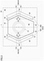
- FIG. 3 is a partial view of an external surface of a front cowl 34.
- the front cowl 34 has an aperture 38 in the inclined area 36.
- the charge connector 30 is disposed inside the aperture 38.
- the electric saddled vehicle has a lid 40.
- the lid 40 is a charging lid and covers the charge connector 30.
- the lid 40 may be for a storage box.
- the lid 40 is attached to the front cowl 34.
- the lid 40 enables opening and closing of the aperture 38 of the front cowl 34.
- the lid 40 is smaller than the aperture 38, the lid 40 is positioned inside the aperture 38, and a periphery of the aperture 38 is opposed to a periphery of the lid 40.
- the lid 40 may be modified to be larger than the aperture 38.
- Such a lid 40 is situated to have an outer edge covering the periphery of the aperture 38.
- the lid 40 may enable remote operation of locking and unlocking. For example, there may be a button next to an unillustrated ignition key, which, when pressed, may cause the lid 40 to open.
- the lid 40 in FIG. 3 is hexagonal in shape.
- the hexagon may have rounded corners.
- the lid 40 has an upper edge 42 and a lower edge 44 on both sides in the upper and lower directions.
- the upper edge 42 and the lower edge 44 are parallel to the vehicle width direction.
- the upper edge 42 and the lower edge 44 may be a straight line or a curve.
- the curve may be convex or concave outward.
- the upper edge 42 and the lower edge 44 are of the same or different length. In the example in FIG. 3 , the lower edge 44 is shorter than the upper edge 42.
- the lower edge 44 may be longer than the upper edge 42.
- the outer shape of the lid 40 has a pair of outer edges 46 spaced in the vehicle width direction.
- the pair of outer edges 46 are positioned to sandwich the upper edge 42 and the lower edge 44.
- An inner angle between the outer edge 46 and each of the upper edge 42 and the lower edge 44 is an obtuse angle.
- the pair of outer edges 46 are a pair of protruding edges convex in an outward direction (direction to be spaced along the vehicle width direction).
- the outer edge 46 may include a straight line or may be a whole curve.
- the pair of outer edges 46 are line-symmetric with respect to a line L being perpendicular to the vehicle width direction and passing through a center (center in the vehicle width direction) of the lid 40.
- the pair of outer edges 46 include a pair of separated outer ends 48 farthest to each other in the vehicle width direction.
- the separated outer ends 48 are at respective vertexes of protruding edges.
- the lid 40 is widest in the vehicle width direction between the pair of separated outer ends 48.
- the pair of separated outer ends 48 may be closer to the upper edge 42 than the lower edge 44, in FIG. 3 , may be equal in distance from the upper edge 42 and the lower edge 44, or may be closer to the lower edge 44 than the upper edge 42.
- the pair of separated outer ends 48 are equal in distance from the center (center of the vehicle width direction) of the lid 40.
- the pair of outer edges 46 include a pair of outer upper inclined sections 50.
- the pair of outer upper inclined sections 50 are closer to each other at respective points higher from the pair of separated outer ends 48.
- the outer upper inclined section 50 may be a straight line or a curve.
- the pair of outer upper inclined sections 50 are line-symmetric with respect to the line L being perpendicular to the vehicle width direction and passing through the center (center of the vehicle width direction) of the lid 40.
- the pair of outer edges 46 include a pair of outer lower inclined sections 52.
- the pair of outer lower inclined sections 52 are closer to each other at respective points lower from the pair of separated outer ends 48.
- the outer lower inclined section 52 may be a straight line or a curve.
- the pair of outer lower inclined sections 52 are line-symmetric with respect to the line L being perpendicular to the vehicle width direction and passing through the center (center of the vehicle width direction) of the lid 40.
- the electric saddled vehicle has a light 54.
- the light 54 is a daytime running light.
- the light 54 is configured to be on or blink during a predetermined period including time of charging the battery 28 in FIG. 2 .
- the light 54 has a light-emitting surface 56 in the inclined area 36 of the front cowl 34.
- the light-emitting surface 56 includes a first light-emitting surface 56A and a second light-emitting surface 56B.
- the first light-emitting surface 56A and the second light-emitting surface 56B are separated from each other.
- the first light-emitting surface 56A and the second light-emitting surface 56B are line-symmetric with respect to the line L being perpendicular to the vehicle width direction and passing through the center (center of the vehicle width direction) of the lid 40.
- the outer shape of the light-emitting surface 56 has a pair of inner edges 58 opposed to the pair of respective outer edges 46.
- the pair of inner edges 58 are a first inner edge 58A of the first light-emitting surface 56A and a second inner edge 58B of the second light-emitting surface 56B.
- the pair of inner edges 58 are a pair of depressed edges concave outward.
- the lid 40 overlaps with a line segment LS between a top point and a bottom point of each inner edge 58.
- the inner edge 58 may include a straight line or may be a whole curve.
- the pair of inner edges 58 are line-symmetric with respect to the line L being perpendicular to the vehicle width direction and passing through the center (center of the vehicle width direction) of the lid 40.
- the pair of inner edges 58 include a pair of separated inner ends 60 farthest to each other in the vehicle width direction.
- the separated inner end 60 is deepest in the depressed edge.
- the pair of separated inner ends 60 may be closer to a top point of the inner edge 58 than a bottom point of the inner edge 58, may be equal in distance from the bottom point and the top point of the inner edge 58, or may be closer to the bottom point of the inner edge 58 than the top point of the inner edge 58.
- the pair of separated inner ends 60 are equal in distance from the center (center of the vehicle width direction) of the lid 40.
- the pair of inner edges 58 include a pair of inner upper inclined sections 62.
- the pair of inner upper inclined sections 62 are closer to each other at respective points higher from the pair of separated inner ends 60.
- the inner upper inclined section 62 is opposed to, may be parallel to, or may be non-parallel to the outer upper inclined section 50 of the lid 40.
- the top point of the inner upper inclined section 62 is lower than the highest portion of the lid 40.
- the pair of inner edges 58 include a pair of inner lower inclined sections 64.
- the pair of inner lower inclined sections 64 are closer to each other at respective points lower from the pair of separated inner ends 60.
- the inner lower inclined section 64 is opposed to, may be parallel to, or may be non-parallel to the outer lower inclined section 52 of the lid 40.
- the bottom point of the inner upper inclined section 62 is higher than the lowest part of the lid 40.
- the light-emitting surface 56 can be closer to the lid 40, improving design flexibility.
- the outer shape of the light-emitting surface 56 (whole of the first light-emitting surface 56A and the second light-emitting surface 56B) has a pair of second outer edges 66 besides the pair of inner edges 58.
- Each of the pair of second outer edges 66 has a shape compatible with a corresponding one of the pair of inner edges 58.
- the second outer edge 66 is in shape along the inner upper inclined section 62 and the inner lower inclined section 64 of the inner edge 58 (e.g. a parallel edge).
- the pair of second outer edges 66 are a pair of protruding edges convex outward (direction away along the vehicle width direction), in response to the pair of outer edges 46 of the lid 40.
- the top point of the second outer edge 66 is higher than the highest portion of the lid 40.
- a second upper edge 68 connecting the inner edge 58 and the second outer edge 66 slopes upward and outward (direction away along the vehicle width direction).
- the bottom point of the second outer edge 66 is higher than the lowest part of the lid 40.
- a second lower edge 70 connecting the inner edge 58 and the second outer edge 66 is parallel to the lower edge 44 of the lid 40.
- FIG. 4 is a partial view of an external surface of a front cowl in a second embodiment.
- a pair of outer edges 246 of a lid 240 include a pair of respective separated outer ends 248 that are highest.
- the pair of outer edges 246 are closer to each other at respective points lower from the pair of separated outer ends 248.
- the upper edge 242 and the lower edge 244 curve to be convex outward.
- the outer shape of the light-emitting surface 256 has an integrated shape continuously surrounding the lid 240 and being laterally beside and under the lid 240. In FIG. 4 , the light-emitting surface 256 avoids being above the lid 240.
- the outer shape of the light-emitting surface 256 has a pair of inner edges 258.
- the pair of inner edges 258 are a pair of depressed edges that are concave outward.
- the lid 240 overlaps with a line segment LS between the top point and the bottom point of each of the pair of inner edges 258.
- the inner edge 258 may include a straight line or may be a whole curve.
- the pair of inner edges 258 are line-symmetric with respect to the line L being perpendicular to the vehicle width direction and passing through the center (center of the vehicle width direction) of the lid 240.
- the pair of inner edges 258 include a pair of separated inner ends 260 that are farthest to each other in the vehicle width direction.
- the separated inner end 260 is deepest in a depressed edge.
- the pair of separated inner ends 260 are opposed to the pair of separated outer ends 248 of the lid 240.
- the pair of inner edges 258 include a pair of respective inner upper inclined sections 262.
- the pair of inner upper inclined sections 262 are closer to each other at respective points higher from the pair of separated inner ends 260.
- the top point of the inner upper inclined section 262 is higher than the highest portion of the lid 240.
- the pair of inner edges 258 include a pair of inner lower inclined sections 264.
- the pair of inner lower inclined sections 264 are closer to each other at respective points lower from the pair of separated inner ends 260.
- the inner lower inclined section 264 is opposed to, may be parallel to, or may be non-parallel to the outer edge 246 of the lid 240.
- the bottom point of the inner upper inclined section 262 is lower than the lowest part of the lid 240.
- the outer shape of the light-emitting surface 256 has an inward lower edge 272 connecting the pair of inner edges 258 under the lid 240.
- the inward lower edge 272 may have a shape consisting of some straight lines or another shape corresponding to the lower edge 244 of the lid 240 (e.g. a shape consisting of an edge parallel to the lower edge 244).
- the outer shape of the light-emitting surface 256 has a pair of second outer edges 266.
- Each of the pair of second outer edges 266 is convex in a direction (outward direction) corresponding to a corresponding one of the pair of inner edges 258.
- the second outer edge 266 has a shape extending along the inner upper inclined section 262 and the inner lower inclined section 264 of the inner edge 258.
- the second outer edge 266 may have a shape with an edge parallel to at least one of the inner upper inclined section 262 and the inner lower inclined section 264.
- the top point of the second outer edge 266 is higher than the highest portion of the lid 240.
- a second upper edge 268 connecting the inner edge 258 and the second outer edge 266 slopes upward and outward (direction away along the vehicle width direction).
- the bottom point of the second outer edge 266 is lower than the lowest part of the lid 240.
- a second lower edge 270 connecting the pair of second outer edges 266 may include an edge parallel to or non-parallel, as shown in FIG. 4 , to the inward lower edge 272.
Applications Claiming Priority (1)
| Application Number | Priority Date | Filing Date | Title |
|---|---|---|---|
| JP2019192187A JP6983847B2 (ja) | 2019-10-21 | 2019-10-21 | 鞍乗型電動車両 |
Publications (2)
| Publication Number | Publication Date |
|---|---|
| EP3812252A1 EP3812252A1 (en) | 2021-04-28 |
| EP3812252B1 true EP3812252B1 (en) | 2022-01-19 |
Family
ID=72801308
Family Applications (1)
| Application Number | Title | Priority Date | Filing Date |
|---|---|---|---|
| EP20200431.3A Active EP3812252B1 (en) | 2019-10-21 | 2020-10-07 | Light for lid of charging connector of electric saddled vehicle |
Country Status (3)
| Country | Link |
|---|---|
| EP (1) | EP3812252B1 (ja) |
| JP (1) | JP6983847B2 (ja) |
| TW (1) | TWI753614B (ja) |
Family Cites Families (20)
| Publication number | Priority date | Publication date | Assignee | Title |
|---|---|---|---|---|
| JP3252035B2 (ja) * | 1993-09-14 | 2002-01-28 | 本田技研工業株式会社 | 電気自動車の充電表示装置 |
| CN2534306Y (zh) * | 2000-12-14 | 2003-02-05 | 光阳工业股份有限公司 | 锁孔照明装置 |
| JP2012176695A (ja) * | 2011-02-25 | 2012-09-13 | Honda Motor Co Ltd | 鞍乗型車両用電源接続部収納構造 |
| WO2013137029A1 (ja) * | 2012-03-14 | 2013-09-19 | 日産自動車株式会社 | 電動車両の充電システムと携帯リモコンキー |
| CN202783526U (zh) * | 2012-09-24 | 2013-03-13 | 朱仁华 | 电动车日间行车灯结构 |
| JP2014110205A (ja) * | 2012-12-04 | 2014-06-12 | Nissan Motor Co Ltd | 充電ポートロック装置 |
| US9764641B2 (en) * | 2014-06-23 | 2017-09-19 | Medallion Instrumentation Systems Llc | System and method for determining a vehicle battery status |
| JP6402384B2 (ja) * | 2014-12-04 | 2018-10-10 | 三菱自動車工業株式会社 | 電動車両の充放電電流量表示装置 |
| CN104986266B (zh) * | 2015-07-31 | 2018-04-27 | 青岛行者智能科技有限公司 | 一种新型独轮平衡车 |
| US9855799B2 (en) * | 2016-02-09 | 2018-01-02 | Ford Global Technologies, Llc | Fuel level indicator |
| JP6905400B2 (ja) * | 2016-09-08 | 2021-07-21 | 株式会社ニフコ | 車両用照明装置 |
| US10890468B2 (en) * | 2017-02-02 | 2021-01-12 | Rebo Lighting & Electronics, Llc | Light ring assembly and method of using the same |
| CN108528578A (zh) * | 2017-03-01 | 2018-09-14 | Tvs电机股份有限公司 | 用于两轮车辆的灯单元 |
| DE102017210946A1 (de) * | 2017-06-28 | 2019-01-03 | Volkswagen Aktiengesellschaft | Beleuchtungsanordnung für einen Funktionsraum eines Fahrzeugs |
| DE102017115106A1 (de) * | 2017-07-06 | 2019-01-10 | Kunststoff Schwanden Ag | Elektrisch betätigbare Tankklappeneinrichtung für ein Fahrzeug und ein solches Fahrzeug |
| WO2019012706A1 (ja) * | 2017-07-14 | 2019-01-17 | 本田技研工業株式会社 | 照明装置 |
| JP2019043286A (ja) * | 2017-08-31 | 2019-03-22 | ヤマハ発動機株式会社 | 鞍乗型電動車両 |
| US11338721B2 (en) * | 2017-10-23 | 2022-05-24 | Koito Manufacturing Co., Ltd. | Vehicle light fixture |
| WO2019155496A1 (en) * | 2018-02-08 | 2019-08-15 | Tvs Motor Company Limited | Straddle type vehicle |
| JP7335866B2 (ja) * | 2018-02-16 | 2023-08-30 | 株式会社小糸製作所 | 自動運転およびバッテリー充電量を表示する車両用灯具システム |
-
2019
- 2019-10-21 JP JP2019192187A patent/JP6983847B2/ja active Active
-
2020
- 2020-10-07 EP EP20200431.3A patent/EP3812252B1/en active Active
- 2020-10-19 TW TW109136077A patent/TWI753614B/zh active
Also Published As
| Publication number | Publication date |
|---|---|
| TW202116607A (zh) | 2021-05-01 |
| TWI753614B (zh) | 2022-01-21 |
| JP6983847B2 (ja) | 2021-12-17 |
| JP2021066290A (ja) | 2021-04-30 |
| EP3812252A1 (en) | 2021-04-28 |
Similar Documents
| Publication | Publication Date | Title |
|---|---|---|
| US9434243B2 (en) | Straddle-type electric vehicle | |
| EP0648633B1 (en) | Electric vehicle comprising a cover structure and battery storing case | |
| JP5999953B2 (ja) | 電動車両 | |
| US9902456B2 (en) | Storage part structure of saddle-ride-type vehicle | |
| US9090310B2 (en) | Straddle-type electric vehicle | |
| US8960754B1 (en) | Utility vehicle | |
| US20160244118A1 (en) | Rear structure for saddle-ride type vehicle | |
| WO2019194000A1 (ja) | 電動車両 | |
| CA3030007C (en) | Structure of electric vehicle | |
| EP3812252B1 (en) | Light for lid of charging connector of electric saddled vehicle | |
| EP2654103B1 (en) | Lead storage battery for vehicle, and vehicle provided with said lead storage battery | |
| CN113365907B (zh) | 跨骑型电动车辆 | |
| JP6224644B2 (ja) | 不整地走行車両 | |
| JP5472532B2 (ja) | 車両 | |
| JP2012171451A (ja) | 鞍乗型車両 | |
| US20160185202A1 (en) | Utility vehicle | |
| EP3498579B1 (en) | Vehicle | |
| EP3150474B1 (en) | Battery compartment for saddle-type vehicle | |
| EP3363725B1 (en) | Straddled vehicle | |
| JP2012171556A (ja) | 鞍乗型車両 | |
| EP1683716B1 (en) | Vehicular article accomodation device | |
| EP1108644B1 (en) | Battery arranging construction for a two-wheeled vehicle | |
| EP2712791B1 (en) | Straddle-type vehicle | |
| US20110221221A1 (en) | Cover structure of saddle ride type vehicle | |
| JP6279867B2 (ja) | 電動車両 |
Legal Events
| Date | Code | Title | Description |
|---|---|---|---|
| PUAI | Public reference made under article 153(3) epc to a published international application that has entered the european phase |
Free format text: ORIGINAL CODE: 0009012 |
|
| STAA | Information on the status of an ep patent application or granted ep patent |
Free format text: STATUS: THE APPLICATION HAS BEEN PUBLISHED |
|
| AK | Designated contracting states |
Kind code of ref document: A1 Designated state(s): AL AT BE BG CH CY CZ DE DK EE ES FI FR GB GR HR HU IE IS IT LI LT LU LV MC MK MT NL NO PL PT RO RS SE SI SK SM TR |
|
| AX | Request for extension of the european patent |
Extension state: BA ME |
|
| STAA | Information on the status of an ep patent application or granted ep patent |
Free format text: STATUS: REQUEST FOR EXAMINATION WAS MADE |
|
| 17P | Request for examination filed |
Effective date: 20210511 |
|
| RBV | Designated contracting states (corrected) |
Designated state(s): AL AT BE BG CH CY CZ DE DK EE ES FI FR GB GR HR HU IE IS IT LI LT LU LV MC MK MT NL NO PL PT RO RS SE SI SK SM TR |
|
| REG | Reference to a national code |
Ref country code: DE Ref legal event code: R079 Ref document number: 602020001675 Country of ref document: DE Free format text: PREVIOUS MAIN CLASS: B62J0006026000 Ipc: B60L0050600000 |
|
| GRAP | Despatch of communication of intention to grant a patent |
Free format text: ORIGINAL CODE: EPIDOSNIGR1 |
|
| STAA | Information on the status of an ep patent application or granted ep patent |
Free format text: STATUS: GRANT OF PATENT IS INTENDED |
|
| RIC1 | Information provided on ipc code assigned before grant |
Ipc: B62J 43/16 20200101ALI20210825BHEP Ipc: B62J 9/12 20200101ALI20210825BHEP Ipc: B62J 6/026 20200101ALI20210825BHEP Ipc: B62J 17/02 20060101ALI20210825BHEP Ipc: B60L 53/16 20190101ALI20210825BHEP Ipc: B60Q 1/50 20060101ALI20210825BHEP Ipc: B60Q 1/00 20060101ALI20210825BHEP Ipc: B60L 50/60 20190101AFI20210825BHEP |
|
| INTG | Intention to grant announced |
Effective date: 20210921 |
|
| GRAS | Grant fee paid |
Free format text: ORIGINAL CODE: EPIDOSNIGR3 |
|
| GRAA | (expected) grant |
Free format text: ORIGINAL CODE: 0009210 |
|
| STAA | Information on the status of an ep patent application or granted ep patent |
Free format text: STATUS: THE PATENT HAS BEEN GRANTED |
|
| AK | Designated contracting states |
Kind code of ref document: B1 Designated state(s): AL AT BE BG CH CY CZ DE DK EE ES FI FR GB GR HR HU IE IS IT LI LT LU LV MC MK MT NL NO PL PT RO RS SE SI SK SM TR |
|
| REG | Reference to a national code |
Ref country code: GB Ref legal event code: FG4D |
|
| REG | Reference to a national code |
Ref country code: CH Ref legal event code: EP |
|
| REG | Reference to a national code |
Ref country code: DE Ref legal event code: R096 Ref document number: 602020001675 Country of ref document: DE |
|
| REG | Reference to a national code |
Ref country code: AT Ref legal event code: REF Ref document number: 1463611 Country of ref document: AT Kind code of ref document: T Effective date: 20220215 |
|
| REG | Reference to a national code |
Ref country code: IE Ref legal event code: FG4D |
|
| REG | Reference to a national code |
Ref country code: LT Ref legal event code: MG9D |
|
| REG | Reference to a national code |
Ref country code: NL Ref legal event code: MP Effective date: 20220119 |
|
| REG | Reference to a national code |
Ref country code: AT Ref legal event code: MK05 Ref document number: 1463611 Country of ref document: AT Kind code of ref document: T Effective date: 20220119 |
|
| PG25 | Lapsed in a contracting state [announced via postgrant information from national office to epo] |
Ref country code: NL Free format text: LAPSE BECAUSE OF FAILURE TO SUBMIT A TRANSLATION OF THE DESCRIPTION OR TO PAY THE FEE WITHIN THE PRESCRIBED TIME-LIMIT Effective date: 20220119 |
|
| PG25 | Lapsed in a contracting state [announced via postgrant information from national office to epo] |
Ref country code: SE Free format text: LAPSE BECAUSE OF FAILURE TO SUBMIT A TRANSLATION OF THE DESCRIPTION OR TO PAY THE FEE WITHIN THE PRESCRIBED TIME-LIMIT Effective date: 20220119 Ref country code: RS Free format text: LAPSE BECAUSE OF FAILURE TO SUBMIT A TRANSLATION OF THE DESCRIPTION OR TO PAY THE FEE WITHIN THE PRESCRIBED TIME-LIMIT Effective date: 20220119 Ref country code: PT Free format text: LAPSE BECAUSE OF FAILURE TO SUBMIT A TRANSLATION OF THE DESCRIPTION OR TO PAY THE FEE WITHIN THE PRESCRIBED TIME-LIMIT Effective date: 20220519 Ref country code: NO Free format text: LAPSE BECAUSE OF FAILURE TO SUBMIT A TRANSLATION OF THE DESCRIPTION OR TO PAY THE FEE WITHIN THE PRESCRIBED TIME-LIMIT Effective date: 20220419 Ref country code: LT Free format text: LAPSE BECAUSE OF FAILURE TO SUBMIT A TRANSLATION OF THE DESCRIPTION OR TO PAY THE FEE WITHIN THE PRESCRIBED TIME-LIMIT Effective date: 20220119 Ref country code: HR Free format text: LAPSE BECAUSE OF FAILURE TO SUBMIT A TRANSLATION OF THE DESCRIPTION OR TO PAY THE FEE WITHIN THE PRESCRIBED TIME-LIMIT Effective date: 20220119 Ref country code: ES Free format text: LAPSE BECAUSE OF FAILURE TO SUBMIT A TRANSLATION OF THE DESCRIPTION OR TO PAY THE FEE WITHIN THE PRESCRIBED TIME-LIMIT Effective date: 20220119 Ref country code: BG Free format text: LAPSE BECAUSE OF FAILURE TO SUBMIT A TRANSLATION OF THE DESCRIPTION OR TO PAY THE FEE WITHIN THE PRESCRIBED TIME-LIMIT Effective date: 20220419 |
|
| PG25 | Lapsed in a contracting state [announced via postgrant information from national office to epo] |
Ref country code: PL Free format text: LAPSE BECAUSE OF FAILURE TO SUBMIT A TRANSLATION OF THE DESCRIPTION OR TO PAY THE FEE WITHIN THE PRESCRIBED TIME-LIMIT Effective date: 20220119 Ref country code: LV Free format text: LAPSE BECAUSE OF FAILURE TO SUBMIT A TRANSLATION OF THE DESCRIPTION OR TO PAY THE FEE WITHIN THE PRESCRIBED TIME-LIMIT Effective date: 20220119 Ref country code: GR Free format text: LAPSE BECAUSE OF FAILURE TO SUBMIT A TRANSLATION OF THE DESCRIPTION OR TO PAY THE FEE WITHIN THE PRESCRIBED TIME-LIMIT Effective date: 20220420 Ref country code: FI Free format text: LAPSE BECAUSE OF FAILURE TO SUBMIT A TRANSLATION OF THE DESCRIPTION OR TO PAY THE FEE WITHIN THE PRESCRIBED TIME-LIMIT Effective date: 20220119 Ref country code: AT Free format text: LAPSE BECAUSE OF FAILURE TO SUBMIT A TRANSLATION OF THE DESCRIPTION OR TO PAY THE FEE WITHIN THE PRESCRIBED TIME-LIMIT Effective date: 20220119 |
|
| PG25 | Lapsed in a contracting state [announced via postgrant information from national office to epo] |
Ref country code: IS Free format text: LAPSE BECAUSE OF FAILURE TO SUBMIT A TRANSLATION OF THE DESCRIPTION OR TO PAY THE FEE WITHIN THE PRESCRIBED TIME-LIMIT Effective date: 20220519 |
|
| REG | Reference to a national code |
Ref country code: DE Ref legal event code: R097 Ref document number: 602020001675 Country of ref document: DE |
|
| PG25 | Lapsed in a contracting state [announced via postgrant information from national office to epo] |
Ref country code: SM Free format text: LAPSE BECAUSE OF FAILURE TO SUBMIT A TRANSLATION OF THE DESCRIPTION OR TO PAY THE FEE WITHIN THE PRESCRIBED TIME-LIMIT Effective date: 20220119 Ref country code: SK Free format text: LAPSE BECAUSE OF FAILURE TO SUBMIT A TRANSLATION OF THE DESCRIPTION OR TO PAY THE FEE WITHIN THE PRESCRIBED TIME-LIMIT Effective date: 20220119 Ref country code: RO Free format text: LAPSE BECAUSE OF FAILURE TO SUBMIT A TRANSLATION OF THE DESCRIPTION OR TO PAY THE FEE WITHIN THE PRESCRIBED TIME-LIMIT Effective date: 20220119 Ref country code: EE Free format text: LAPSE BECAUSE OF FAILURE TO SUBMIT A TRANSLATION OF THE DESCRIPTION OR TO PAY THE FEE WITHIN THE PRESCRIBED TIME-LIMIT Effective date: 20220119 Ref country code: DK Free format text: LAPSE BECAUSE OF FAILURE TO SUBMIT A TRANSLATION OF THE DESCRIPTION OR TO PAY THE FEE WITHIN THE PRESCRIBED TIME-LIMIT Effective date: 20220119 Ref country code: CZ Free format text: LAPSE BECAUSE OF FAILURE TO SUBMIT A TRANSLATION OF THE DESCRIPTION OR TO PAY THE FEE WITHIN THE PRESCRIBED TIME-LIMIT Effective date: 20220119 |
|
| PLBE | No opposition filed within time limit |
Free format text: ORIGINAL CODE: 0009261 |
|
| STAA | Information on the status of an ep patent application or granted ep patent |
Free format text: STATUS: NO OPPOSITION FILED WITHIN TIME LIMIT |
|
| PG25 | Lapsed in a contracting state [announced via postgrant information from national office to epo] |
Ref country code: AL Free format text: LAPSE BECAUSE OF FAILURE TO SUBMIT A TRANSLATION OF THE DESCRIPTION OR TO PAY THE FEE WITHIN THE PRESCRIBED TIME-LIMIT Effective date: 20220119 |
|
| 26N | No opposition filed |
Effective date: 20221020 |
|
| PG25 | Lapsed in a contracting state [announced via postgrant information from national office to epo] |
Ref country code: MC Free format text: LAPSE BECAUSE OF FAILURE TO SUBMIT A TRANSLATION OF THE DESCRIPTION OR TO PAY THE FEE WITHIN THE PRESCRIBED TIME-LIMIT Effective date: 20220119 |
|
| REG | Reference to a national code |
Ref country code: BE Ref legal event code: MM Effective date: 20221031 |
|
| PG25 | Lapsed in a contracting state [announced via postgrant information from national office to epo] |
Ref country code: LU Free format text: LAPSE BECAUSE OF NON-PAYMENT OF DUE FEES Effective date: 20221007 |
|
| P01 | Opt-out of the competence of the unified patent court (upc) registered |
Effective date: 20230527 |
|
| PG25 | Lapsed in a contracting state [announced via postgrant information from national office to epo] |
Ref country code: BE Free format text: LAPSE BECAUSE OF NON-PAYMENT OF DUE FEES Effective date: 20221031 |
|
| PG25 | Lapsed in a contracting state [announced via postgrant information from national office to epo] |
Ref country code: IE Free format text: LAPSE BECAUSE OF NON-PAYMENT OF DUE FEES Effective date: 20221007 |
|
| PGFP | Annual fee paid to national office [announced via postgrant information from national office to epo] |
Ref country code: IT Payment date: 20231031 Year of fee payment: 4 Ref country code: FR Payment date: 20231026 Year of fee payment: 4 Ref country code: DE Payment date: 20231020 Year of fee payment: 4 |
|
| PG25 | Lapsed in a contracting state [announced via postgrant information from national office to epo] |
Ref country code: CY Free format text: LAPSE BECAUSE OF FAILURE TO SUBMIT A TRANSLATION OF THE DESCRIPTION OR TO PAY THE FEE WITHIN THE PRESCRIBED TIME-LIMIT Effective date: 20220119 |