EP3804597A1 - Staubsauger - Google Patents
Staubsauger Download PDFInfo
- Publication number
- EP3804597A1 EP3804597A1 EP20194953.4A EP20194953A EP3804597A1 EP 3804597 A1 EP3804597 A1 EP 3804597A1 EP 20194953 A EP20194953 A EP 20194953A EP 3804597 A1 EP3804597 A1 EP 3804597A1
- Authority
- EP
- European Patent Office
- Prior art keywords
- vacuum cleaner
- power cable
- cable
- housing
- cable duct
- Prior art date
- Legal status (The legal status is an assumption and is not a legal conclusion. Google has not performed a legal analysis and makes no representation as to the accuracy of the status listed.)
- Granted
Links
Images


Classifications
-
- A—HUMAN NECESSITIES
- A47—FURNITURE; DOMESTIC ARTICLES OR APPLIANCES; COFFEE MILLS; SPICE MILLS; SUCTION CLEANERS IN GENERAL
- A47L—DOMESTIC WASHING OR CLEANING; SUCTION CLEANERS IN GENERAL
- A47L5/00—Structural features of suction cleaners
- A47L5/12—Structural features of suction cleaners with power-driven air-pumps or air-compressors, e.g. driven by motor vehicle engine vacuum
- A47L5/22—Structural features of suction cleaners with power-driven air-pumps or air-compressors, e.g. driven by motor vehicle engine vacuum with rotary fans
- A47L5/36—Suction cleaners with hose between nozzle and casing; Suction cleaners for fixing on staircases; Suction cleaners for carrying on the back
- A47L5/362—Suction cleaners with hose between nozzle and casing; Suction cleaners for fixing on staircases; Suction cleaners for carrying on the back of the horizontal type, e.g. canister or sledge type
-
- A—HUMAN NECESSITIES
- A47—FURNITURE; DOMESTIC ARTICLES OR APPLIANCES; COFFEE MILLS; SPICE MILLS; SUCTION CLEANERS IN GENERAL
- A47L—DOMESTIC WASHING OR CLEANING; SUCTION CLEANERS IN GENERAL
- A47L9/00—Details or accessories of suction cleaners, e.g. mechanical means for controlling the suction or for effecting pulsating action; Storing devices specially adapted to suction cleaners or parts thereof; Carrying-vehicles specially adapted for suction cleaners
-
- A—HUMAN NECESSITIES
- A47—FURNITURE; DOMESTIC ARTICLES OR APPLIANCES; COFFEE MILLS; SPICE MILLS; SUCTION CLEANERS IN GENERAL
- A47L—DOMESTIC WASHING OR CLEANING; SUCTION CLEANERS IN GENERAL
- A47L9/00—Details or accessories of suction cleaners, e.g. mechanical means for controlling the suction or for effecting pulsating action; Storing devices specially adapted to suction cleaners or parts thereof; Carrying-vehicles specially adapted for suction cleaners
- A47L9/10—Filters; Dust separators; Dust removal; Automatic exchange of filters
- A47L9/16—Arrangement or disposition of cyclones or other devices with centrifugal action
-
- A—HUMAN NECESSITIES
- A47—FURNITURE; DOMESTIC ARTICLES OR APPLIANCES; COFFEE MILLS; SPICE MILLS; SUCTION CLEANERS IN GENERAL
- A47L—DOMESTIC WASHING OR CLEANING; SUCTION CLEANERS IN GENERAL
- A47L9/00—Details or accessories of suction cleaners, e.g. mechanical means for controlling the suction or for effecting pulsating action; Storing devices specially adapted to suction cleaners or parts thereof; Carrying-vehicles specially adapted for suction cleaners
- A47L9/26—Incorporation of winding devices for electric cables
Definitions
- the invention relates to a vacuum cleaner with a housing in which a fan module for generating a suction air flow is arranged, the vacuum cleaner having a power cable, the power cable being configured to supply the vacuum cleaner with electrical energy, the vacuum cleaner having a power cable storage device in the housing wherein the power cable storage device is set up to store the power cable, unwind the power cable and / or automatically wind up the power cable, a power cable outlet module being arranged in the housing, the power cable outlet module being designed to store an end section of the power cable.
- vacuum cleaners with a power cable storage device which have a power cable outlet module in the housing, which is directly connected to the power cable storage device.
- This enables a particularly compact arrangement of the power cable storage device and power cable outlet module in the housing of the vacuum cleaner and, at the same time, causes only a relatively low manufacturing effort.
- the disadvantage here is that when the vacuum cleaner is being cleaned, loops can form in the course of the automatic winding of the power cord. At this time, the power cord is not wound evenly on the power cord storage device, but the power cord becomes tangled. These occur in particular when a longer section of the power cord lies directly next to the vacuum cleaner and is to be wound onto the power cord storage device. As a result of this so-called loop formation in the power cable, it can no longer be completely wound up in the power cable storage device or a subsequent unwinding of the power cable from the power cable storage device is no longer possible without interference.
- the invention thus addresses the problem of providing a vacuum cleaner with a power cable storage device which enables the power cable to be wound and unwound from the power cable storage device as far as possible without interference. According to the invention, this problem is solved by a vacuum cleaner with the features of claim 1. Advantageous refinements and developments of the invention emerge from the subclaims.
- the housing of the vacuum cleaner forms a cable duct, the cable duct extending from the power cable storage device to the power cable outlet module.
- the cable duct is designed in such a way that it Power cord completely encompassed along the entire length of the cable duct.
- the cable duct in the housing of the vacuum cleaner forms a tunnel which extends continuously from the power cable storage device to the power cable outlet module.
- the cable duct has an opening at its first end and a second opening for the power cable at its second end.
- the cable duct is designed to be completely closed along its entire length.
- a power cable can be a power cable which is suitable for connecting the vacuum cleaner to an electrical supply network and for supplying it with electrical energy during cleaning operation.
- a power cord storage device can be a cable reel.
- the cable drum is designed to accommodate the mains cable almost completely.
- One end section of the power cable is a power plug which is designed to connect the power cable to an electrical supply network.
- the power cable outlet module is designed to mount the end section of the power cable in a form-fitting manner.
- the power cable outlet module can be designed in one piece with a housing part of the vacuum cleaner or the cable duct. In an alternative embodiment, however, it is also conceivable to design the power cable outlet module as a separate component which is positively and / or non-positively connected to a housing part of the vacuum cleaner and / or to the cable duct.
- a cable duct according to the invention improves the winding behavior of the power cable storage device of a vacuum cleaner.
- the so-called looping of a power cable in the course of winding it onto a power cable storage device is thereby almost completely avoided.
- the cable duct has a length between 50 and 200 millimeters.
- the cable duct extends from the power cable storage device to the power cable outlet module.
- a cable duct with the preferred length ensures that the power cable has to travel a longer distance from the power cable outlet module to the power cable storage device in the course of winding. This additional guided path of the power cable causes a straightening of the power cable before it is wound up on the power cable storage device. As a result, the power cord can be wound and unwound more evenly and orderly on the power cord storage device.
- the cable duct has a width between 20 and 70 millimeters.
- the cable duct has a greater width at its first end on the power cable storage device than at its second end on the power cable outlet module.
- the width of the cable duct at its first end is based on the width of the power cable storage element of the power cable storage device.
- the cable duct has a height between 10 and 30 millimeters.
- the cable duct has a greater height at its first end on the power cable storage device than at its second end on the power cable outlet module.
- the cable duct forms an incline from a first end on the power cable storage device to a second end on the power cable outlet module.
- the slope of the cable duct is designed so that in a normal operating position of the vacuum cleaner the first end of the cable duct is arranged lower than the second end of the cable duct. Because of the incline of the cable duct, the second end of the cable duct is at a greater distance from the underside of the housing of the vacuum cleaner than the first end of the cable duct.
- the slope of the cable duct is uniform along the entire course of the cable duct. In an alternative embodiment, however, it is also conceivable that the cable duct has a first section with a first slope and a second section with a second slope. A slope of the cable duct in the range between 3 and 20 degrees is particularly preferred.
- a cable duct with a preferred incline improves the supply and removal of the power cable from the power cable storage device.
- the cable duct forms a first opening at a first end and forms a second opening at a second end, the first and second openings having an approximately rectangular base area.
- the first and second openings of the cable duct are designed to feed the power cable into and out of the cable duct.
- the first opening of the cable duct is designed to be laterally offset with respect to the second opening of the cable duct.
- the cable duct is designed so that the first opening is not aligned with the second opening of the cable duct.
- the second opening of the cable duct is laterally offset by 3 to 20 millimeters compared to the first opening.
- the cable duct is formed by a first housing part and a second housing part.
- a first housing part can be a bottom shell of the vacuum cleaner.
- a second housing part can be an upper shell or an inner wall of the vacuum cleaner.
- the power cable outlet module has a power cable cleaning element.
- the mains cable cleaning element can be, for example, a brush element or a textile element which is arranged in or on the mains cable outlet module.
- the power cable cleaning element is designed to clean the power cable from adhering dust and dirt particles when it is wound and unwound on the power cable storage device.
- a power cable cleaning element significantly reduces the amount of dirt entering the power cable storage device. This reduces the risk of a blockage or damage to the power cord storage device as a result of dirt particles adhering to the power cord.
- the cable duct is arranged below a separation unit of the vacuum cleaner in its housing.
- the arrangement of the cable duct below the separation unit relates to the normal operating position of the vacuum cleaner.
- a separation unit is, for example, a cyclone separator with a dust collection container or a dust bag space in which a dust bag can be accommodated.
- the use of a cable duct opens up additional straight lines of freedom with regard to the distribution of required device components in a housing of a vacuum cleaner. In this way, electrical components such as the power cable storage device, fan module and control electronics can be arranged directly next to one another in the housing of the vacuum cleaner.
- the arrangement of the separation unit in the housing can be optimized from the point of view of handling or flow technology.
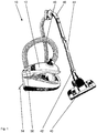
- FIG. 10 shows a perspective view of a vacuum cleaner 10 according to the prior art.
- the vacuum cleaner 10 is a floor vacuum cleaner with a floor nozzle 40 connected to the vacuum cleaner.
- the floor nozzle 10 is connected via its connecting piece 42 to a suction pipe 44, which is preferably designed to be telescopic.
- the telescopic suction tube 44 merges into the handle 46, to which a suction hose 48 is connected, which is connected to the vacuum cleaner housing 12.
- a blower module (not shown) of the vacuum cleaner 10, which is integrated in the housing 12, is operated with electricity via an electrical mains cable 14 in order to generate a negative pressure.
- a separation unit 34 is provided, which is designed as a dust bag in the exemplary embodiment.
- This separation unit 34 is located in a dust space formed by the housing parts of the vacuum cleaner 10. This dust space is accessible and opened by a folding mechanism between the vacuum cleaner housing parts, so that the separation unit 34 is visible and can be removed.
- a negative pressure is generated for the operation of the vacuum cleaner 10. The air flow generated by the negative pressure is freed of dirt and grime in the separating unit 34 and passed out of the vacuum cleaner 10 via an exhaust air grille.
- This step circuit 50 includes switches that are sufficiently large that a user can operate them with his foot.
- the step switch 50 usually also has a switch for actuating the power cable storage device (not shown) integrated in the vacuum cleaner housing 12 for winding up the power cable 14.
- a user of the vacuum cleaner 10 can take hold of the handle 46 and thus push the floor nozzle 40 back and forth in a pushing and pulling movement in order to clean a floor surface.
- the in Figure 1 The prior art vacuum cleaner 10 shown is the power cord storage device (not shown in FIG Figure 1 ) arranged below the step switch 50 in the housing 12 of the vacuum cleaner 10.
- the power cable storage device is arranged on the edge of the housing 12 in such a way that the power cable 14 from the power cable storage device directly into the power cable outlet module (not shown in FIG Figure 1 ) is transferred.
- the power cable outlet module is integrated into the housing 12 of the vacuum cleaner 10 and the power cable storage device is arranged directly next to the power cable outlet module.
- FIG. 2 shows a sectional view of a vacuum cleaner 10 according to the invention with a cable duct 22.
- the housing 12 of the vacuum cleaner 10 has a lower shell 52 in which a power cable storage device 16, a cable shaft 22, a power cable outlet module 18 and a separation unit 34 are added.
- the power cable storage device 16 and the power cable outlet module 18 are arranged at a distance from one another in the housing 12 and are connected to one another via a cable duct 22.
- the cable duct 22 is arranged below the separation unit 34 and extends approximately over its entire width.
- the cable duct 22 is arranged with a first end 24 at the mains cable output of the mains cable storage device 16 and with its second end 26 the cable duct 22 is arranged on the mains cable outlet module 18.
- the lower half of the cable duct 22 is formed by the lower shell 52 of the housing 12.
- the upper half of the cable duct 22 is formed by an intermediate wall 54 of the housing 12.
- the cable duct 22 has an incline starting from its first end 24 in the direction of its second end 26.
- the second end 26 of the cable duct 22 is thus arranged in the housing 12 of the vacuum cleaner 10 in an increased manner relative to the first end 24.
- the cable outlet module 18 is designed as a separate component and is positively connected to the housing 12 of the vacuum cleaner 10.
- the cable outlet module 18 forms a cable outlet opening at which the power cable emerges from the housing 12 of the vacuum cleaner 10.
- the cable exit opening of the cable exit module 18 is made significantly smaller than the opposite cable entry opening of the cable exit module 18.
- a power cable cleaning element 32 is additionally arranged at the cable exit opening and protrudes from the outside into the cable exit opening.
- Figure 3 shows a further sectional view of a vacuum cleaner 10 according to the invention with a cable duct 22.
- This is a sectional view showing the cable outlet module 18, the cable duct 22 and the power cable storage device 16 in a plan view.
- the first opening 36 of the cable duct 22 is laterally offset at its first end 24 with respect to the second opening 38 at the second end 26.
- the width of the second opening 38 of the cable duct 22 is reduced compared to the width of the first opening 36.
Landscapes
- Engineering & Computer Science (AREA)
- Mechanical Engineering (AREA)
- Electric Vacuum Cleaner (AREA)
Abstract
Description
- Die Erfindung betrifft einen Staubsauger mit einem Gehäuse in dem ein Gebläsemodul zum Erzeugen eines Saugluftstromes angeordnet ist, wobei der Staubsauger ein Netzkabel aufweist, wobei das Netzkabel dazu eingerichtet ist, den Staubsauger mit elektrischer Energie zu versorgen, wobei der Staubsauger im Gehäuse eine Netzkabel-Lagervorrichtung aufweist, wobei die Netzkabel-Lagervorrichtung dazu eingerichtet ist, das Netzkabel zu lagern, das Netzkabel abzuwickeln und/oder das Netzkabel automatisch aufzuwickeln, wobei im Gehäuse ein Netzkabelaustrittsmodul angeordnet ist, wobei das Netzkabelaustrittsmodul dazu ausgebildet ist, einen Endabschnitt des Netzkabels zu lagern.
- Im Stand der Technik, wie beispielsweise durch die
EP 2 078 489 A2 offenbart, sind Staubsauger mit einer Netzkabel-Lagervorrichtung bekannt, die im Gehäuse ein Netzkabelaustrittsmodul aufweisen, welches sich unmittelbar an die Netzkabel-Lagervorrichtung anschließt. Dies ermöglicht eine besonders kompakte Anordnung von Netzkabel-Lagervorrichtung und Netzkabelaustrittsmodul im Gehäuse des Staubsaugers und verursacht gleichzeitig nur einen relativ geringen fertigungstechnischen Aufwand. Nachteilig hierbei ist es, dass es im Reinigungsbetrieb des Staubsaugers im Zuge des automatischen Aufwickelns des Netzkabels zu einer Schlaufenbildung kommen kann. Hierbei wird das Netzkabel nicht gleichmäßig auf der Netzkabel-Lagervorrichtung aufgewickelt, sondern es treten Verwickelungen des Netzkabels auf. Diese treten insbesondere dann auf, wenn ein längerer Abschnitt des Netzkabels unmittelbar neben dem Staubsauger liegt und auf die Netzkabel-Lagervorrichtung aufgewickelt werden soll. In Folge dieser sogenannten Schlaufenbildung des Netzkabels lässt sich dieses nicht mehr vollständig in der Netzkabel-Lagervorrichtung aufwickeln oder ein darauffolgendes Abwickeln des Netzkabels von der Netzkabel-Lagervorrichtung ist nicht mehr störungsfrei möglich. - Der Erfindung stellt sich somit das Problem einen Staubsauger mit einer Netzkabel-Lagervorrichtung zur Verfügung zu stellen, welcher ein weitestgehend störungsfreies Auf- und Abwickeln des Netzkabels von der Netzkabel-Lagervorrichtung ermöglicht. Erfindungsgemäß wird dieses Problem durch einen Staubsauger mit den Merkmalen des Patentanspruchs 1 gelöst. Vorteilhafte Ausgestaltungen und Weiterbildungen der Erfindung ergeben sich aus den Unteransprüchen.
- Erfindungsgemäß bildet das Gehäuse des Staubsaugers einen Kabelschacht aus, wobei sich der Kabelschacht von der Netzkabel-Lagervorrichtung bis zum Netzkabelaustrittsmodul erstreckt. Der Kabelschacht ist in einer Ausführungsform so ausgebildet, dass dieser das Netzkabel entlang der gesamten Länge des Kabelschachtes vollständig umfasst. Mit anderen Worten bildet der Kabelschacht im Gehäuse des Staubsaugers einen Tunnel aus, welcher sich von der Netzkabel-Lagervorrichtung bis zum Netzkabelaustrittsmodul durchgehend erstreckt. Der Kabelschacht weist dabei an seinem ersten Ende eine Öffnung und an seinem zweiten Ende eine zweite Öffnung für das Netzkabel auf. In einer bevorzugten Ausführungsform ist der Kabelschacht entlang seiner gesamten Länge vollumfänglich geschlossen ausgebildet.
- Bei einem Netzkabel kann es sich um ein Stromkabel handeln, welches geeignet ist, den Staubsauger mit einem elektrischen Versorgungsnetz zu verbinden und im Reinigungsbetrieb mit elektrischer Energie zu versorgen. Bei einer Netzkabel-Lagervorrichtung kann es sich um eine Kabeltrommel handeln. Dabei ist die Kabeltrommel dazu ausgebildet, das Netzkabel annähernd vollständig aufzunehmen. Bei einem Endabschnitt des Netzkabels handelt es sich um einen Netzstecker, welcher dazu ausgebildet ist, das Netzkabel mit einem elektrischen Versorgungsnetz zu verbinden. Das Netzkabelaustrittsmodul ist dazu ausgebildet, den Endabschnitt des Netzkabels formschlüssig zu lagern. Das Netzkabelaustrittsmodul kann dabei einstückig mit einem Gehäuseteil des Staubsaugers oder dem Kabelschacht ausgeführt sein. In einer alternativen Ausführungsform ist es aber auch denkbar, das Netzkabelaustrittsmodul als ein gesondertes Bauteil auszubilden, welches form- und/oder kraftschlüssig mit einem Gehäuseteil des Staubsaugers und/oder mit dem Kabelschacht verbunden ist.
- Ein erfindungsgemäßer Kabelschacht verbessert das Aufwickelverhalten der Netzkabel-Lagervorrichtung eines Staubsaugers. Die sogenannte Schlaufenbildung eines Netzkabels im Zuge des Aufwickelns auf eine Netzkabel-Lagervorrichtung wird dadurch annähernd vollständig vermieden.
- Dabei ist es bevorzugt, dass der Kabelschacht eine Länge zwischen 50 und 200 Millimetern aufweist. Der Kabelschacht erstreckt sich dabei von der Netzkabel-Lagervorrichtung bis zum Netzkabelaustrittsmodul. Durch einen Kabelschacht mit der bevorzugten Länge wird erreicht, dass das Netzkabel vom Netzkabelaustrittsmodul bis zur Netzkabel-Lagervorrichtung im Zuge des Aufwickelns einen längeren Weg zurücklegen muss. Dieser zusätzliche geführte Weg des Netzkabels bewirkt eine Begradigung Netzkabels bevor dieses auf der Netzkabel-Lagervorrichtung aufgewickelt wird. In der Folge lässt sich das Netzkabel gleichmäßiger und geordneter auf der Netzkabel-Lagervorrichtung auf- und abwickeln.
- In einer bevorzugten Ausführungsform weist der Kabelschacht eine Breite zwischen 20 und 70 Millimetern auf. Der Kabelschacht weist dabei an seinem ersten Ende an der Netzkabel-Lagervorrichtung eine größere Breite als an seinem zweiten Ende am Netzkabelaustrittsmodul auf. Die Breite des Kabelschachtes an seinem ersten Ende orientiert sich an der Breite des Netzkabel-Lagerelementes der Netzkabel-Lagervorrichtung. In einer alternativen Ausführungsform ist es aber auch denkbar, den Kabelschacht in einer einheitlichen Breite entlang seines gesamten Verlaufes auszubilden. Ein Kabelschacht in der bevorzugten Breite gewährleistet ein störungsfreies Zu- und Abführen des Netzkabels von der Netzkabel-Lagervorrichtung.
- Weiterhin ist es bevorzugt, dass der Kabelschacht eine Höhe zwischen 10 und 30 Millimetern aufweist. Der Kabelschacht weist dabei an seinem ersten Ende an der Netzkabel-Lagervorrichtung eine größere Höhe als an seinem zweiten Ende am Netzkabelaustrittsmodul auf. In einer alternativen Ausführungsform ist es aber auch denkbar, den Kabelschacht in einer einheitlichen Höhe entlang seines gesamten Verlaufes auszubilden.
- Bevorzugt ist, dass der Kabelschacht ausgehend von einem ersten Ende an der Netzkabel-Lagervorrichtung zu einem zweiten Ende am Netzkabelaustrittsmodul eine Steigung ausbildet. Die Steigung des Kabelschachtes ist so ausgebildet, dass in einer normalen Betriebsposition des Staubsaugers das erste Ende des Kabelschachtes niedriger als das zweite Ende des Kabelschachtes angeordnet ist. Aufgrund der Steigung des Kabelschachtes weist das zweite Ende des Kabelschachtes einen größeren Abstand zu einer Gehäuseunterseite des Staubsaugers auf als das erste Ende des Kabelschachtes. Die Steigung des Kabelschachtes ist dabei gleichmäßig entlang des gesamten Verlaufes des Kabelschachtes ausgebildet. In einer alternativen Ausführungsform ist es aber auch denkbar, dass der Kabelschacht einen ersten Abschnitt mit einer ersten Steigung und einen zweiten Abschnitt mit einer zweiten Steigung aufweist. Insbesondere bevorzugt ist dabei eine Steigung des Kabelschachtes im Bereich zwischen 3 und 20 Grad. Ein Kabelschacht mit einer bevorzugten Steigung verbessert das Zu- und Abführen des Netzkabels von der Netzkabel-Lagervorrichtung zusätzlich.
- In einer weiteren Ausführungsform ist es bevorzugt, dass der Kabelschacht an einem ersten Ende eine erste Öffnung ausbildet und an einem zweiten Ende eine zweite Öffnung ausbildet, wobei die erste und zweite Öffnung eine annähernd rechteckige Grundfläche aufweisen. Die erste und zweite Öffnung des Kabelschachtes sind dazu ausgebildet, das Netzkabel in den Kabelschacht ein- und auszuführen. In einer alternativen Ausführungsform ist es aber auch denkbar, die erste und zweite Öffnung des Kabelschachtes mit einer runden oder ovalen Grundfläche auszubilden. Öffnungen des Kabelschachtes in einer bevorzugten Grundform verhindern ein Verklemmen oder eine Beschädigung des Netzkabels im Zuge des Ein- oder Aufwickelns des Netzkabels auf die Netzkabel-Lagervorrichtung.
- Weiterhin ist es bevorzugt, dass die erste Öffnung des Kabelschachts gegenüber der zweiten Öffnung des Kabelschachtes seitlich versetzt ausgebildet ist. Der Kabelschacht ist dabei so ausgebildet, dass die erste Öffnung nicht fluchtend mit der zweiten Öffnung des Kabelschachtes ausgerichtet ist. Die zweite Öffnung des Kabelschachtes ist um 3 bis 20 Millimetern gegenüber der ersten Öffnung seitlich versetzt.
- Bevorzugt ist, dass der Kabelschacht durch ein erstes Gehäuseteil und ein zweites Gehäuseteil ausgebildet wird. Bei einem ersten Gehäuseteil kann es sich dabei um eine Bodenschale des Staubsaugers handeln. Bei einem zweiten Gehäuseteil kann es sich dabei um eine Oberschale oder eine Innenwand des Staubsaugers handeln. In einer alternativen Ausführungsform ist es aber auch denkbar, den Kabelschacht als ein gesondertes Bauteil auszuführen, welches zwischen der Ober- und Unterschale des Staubsauger-Gehäuses form- und/oder kraftschlüssig angeordnet wird. Die Bildung des Kabelschachtes durch Gehäuseteile einer vorhandenen Staubsauger-Gerätearchitektur reduziert die fertigungstechnischen Aufwände.
- Gemäß einer Ausführungsform ist es bevorzugt, dass das Netzkabelaustrittsmodul ein Netzkabelreinigungselement aufweist. Beim Netzkabelreinigungselement kann es sich beispielsweise um ein Bürstenelement oder ein Textilelement handeln, welches im oder am Netzkabelaustrittsmodul angeordnet ist. Das Netzkabelreinigungselement ist dazu ausgebildet, das Netzkabel beim Auf- und Abwickeln auf die Netzkabel-Lagervorrichtung von anhaftenden Staub- und Schmutzpartikeln zu reinigen. Durch ein Netzkabelreinigungselement wird der Schmutzeintrag in die Netzkabel-Lagervorrichtung signifikant reduziert. Dies reduziert das Risiko einer Blockade oder eine Beschädigung der Netzkabel-Lagervorrichtung infolge von dem Netzkabel anhaftenden Schmutzpartikeln.
- Zudem ist es bevorzugt, dass der Kabelschacht unterhalb einer Abscheideeinheit des Staubsaugers in dessen Gehäuse angeordnet ist. Die Anordnung des Kabelschachtes unterhalb der Abscheideeinheit bezieht sich auf die normale Betriebsposition des Staubsaugers. In einer alternativen Ausführungsform wäre es aber auch denkbar, den Kabelschacht neben einer Abscheideeinheit im Gehäuse des Staubsaugers vorbeizuführen. Bei einer Abscheideeinheit handelt es sich beispielweise um einen Zyklonabscheider mit einem Staubsammelbehälter oder um einen Staubbeutelraum, in welchem ein Staubbeutel aufgenommen werden kann. Die Verwendung eines Kabelschachtes erschließt zusätzliche Freiheitsgerade in Bezug auf die Verteilung von erforderlichen Gerätekomponenten in einem Gehäuse eines Staubsaugers. Auf diese Weise können elektrischen Komponenten wie Netzkabel-Lagervorrichtung, Gebläsemodul und Steuerungselektronik unmittelbar nebeneinander im Gehäuse des Staubsaugers angeordnet werden. Zusätzlich lässt sich die Anordnung der Abscheideeinheit im Gehäuse aus handhabungs- oder strömungstechnischen Gesichtspunkten optimieren.
- Ein Ausführungsbeispiel der Erfindung ist in den Zeichnungen rein schematisch dargestellt und wird nachfolgend näher beschrieben. Es zeigen:
- Figur 1
- Perspektivische Ansicht eines Staubsaugers gemäß dem Stand der Technik;
- Figur 2
- Schnittansicht eines erfindungsgemäßen Staubsaugers;
- Figur 3
- Schnittansicht eines erfindungsgemäßen Staubsaugers.
-
Figur 1 zeigt eine perspektivische Ansicht eines Staubsaugers 10 gemäß dem Stand der Technik. Bei dem Staubsauger 10 handelt es sich um einen Bodenstaubsauger mit einer an den Staubsauger angeschlossenen Bodendüse 40. Die Bodendüse 10 ist über ihren Anschlussstutzen 42 mit einem vorzugsweise teleskopierbar-ausgestalteten Saugrohr 44 verbunden. Das teleskopierbare Saugrohr 44 geht in den Handgriff 46 über, an dem ein Saugschlauch 48 angeschlossen ist, der mit dem Staubsaugergehäuse 12 verbunden ist. Über ein elektrisches Netzkabel 14 wird ein in dem Gehäuse 12 integriertes (nicht dargestelltes) Gebläsemodul des Staubsaugers 10 mit Strom betrieben, um einen Unterdruck zu erzeugen. Mittels dieses Unterdruckes wird Schmutz und Dreck von der zu reinigenden Bodenfläche durch einen Luftstrom über den Saugmund der Bodendüse 40 aufgenommen und über das Saugrohr 44, den Handgriff 46 und den Saugschlauch 48 in das Gehäuse 12 des Staubsaugers 10 abtransportiert. In diesem Gehäuse 12 ist eine Abscheideeinheit 34 vorgesehen, welche im Ausführungsbeispiel als Staubbeutel ausgebildet ist. Diese Abscheideeinheit 34 befindet sich in einem durch die Gehäuseteile des Staubsaugers 10 gebildeten Staubraum. Dieser Staubraum ist durch einen Klappmechanismus zwischen den Staubsaugergehäuseteilen zugänglich und geöffnet dargestellt, sodass die Abscheideeinheit 34 sichtbar und entnehmbar ist. Für den Betrieb des Staubsaugers 10 wird ein Unterdruck erzeugt. Der durch den Unterdruck erzeugte Luftstrom wird in der Abscheideeinheit 34 von Schmutz und Dreck befreit und über ein Abluftgitter aus dem Staubsauger 10 herausgeleitet. - Zum Ein- und Ausschalten des Staubsaugers 10 weist dieser eine Trittschaltung 50 auf. Diese Trittschaltung 50 umfasst Schalter, die ausreichend groß sind, damit ein Benutzer diese mit dem Fuß betätigen kann. Die Trittschaltung 50 weist üblicherweise auch einen Schalter zur Betätigung der im Staubsaugergehäuse 12 integrierten (nicht dargestellten) Netzkabel-Lagervorrichtung zum Aufwickeln des Netzkabels 14 auf. Ein Benutzer des Staubsaugers 10 kann diesen an dem Handgriff 46 ergreifen und so die Bodendüse 40 in einer Schub- und Zugbewegung vor- und zurückschieben, um eine Bodenfläche zu reinigen.
- Bei dem in
Figur 1 gezeigte Staubsauger 10 gemäß dem Stand der Technik ist die Netzkabel-Lagervorrichtung (nicht dargestellt inFigur 1 ) unterhalb der Trittschaltung 50 im Gehäuse 12 des Staubsaugers 10 angeordnet. Dabei ist die Netzkabel-Lagervorrichtung so am Rand des Gehäuses 12 angeordnet, dass das Netzkabel 14 aus der Netzkabel-Lagervorrichtung direkt in das Netzkabelaustrittsmodul (nicht dargestellt inFigur 1 ) überführt wird. Dabei ist das Netzkabelaustrittsmodul in das Gehäuse 12 des Staubsaugers 10 integriert und die Netzkabel-Lagervorrichtung ist unmittelbar neben dem Netzkabelaustrittsmodul angeordnet. -
Figur 2 zeigt eine Schnittansicht eines erfindungsgemäßen Staubsaugers 10 mit einem Kabelschacht 22. Das Gehäuse 12 des Staubsaugers 10 weist eine Unterschale 52 auf, in welcher eine Netzkabel-Lagervorrichtung 16, ein Kabelschacht 22, ein Netzkabelaustrittsmodul 18 und eine Abscheideeinheit 34 aufgenommen sind. Die Netzkabel-Lagervorrichtung 16 und das Netzkabelaustrittsmodul 18 sind dabei beabstandet voneinander im Gehäuse 12 angeordnet und werden über einen Kabelschacht 22 miteinander verbunden. Der Kabelschacht 22 ist unterhalb der Abscheideeinheit 34 angeordnet und erstreckt sich annähernd über deren gesamte Breite. Mit einem ersten Ende 24 ist der Kabelschacht 22 an der Netzkabel-Ausgabe der Netzkabel-Lagervorrichtung 16 angeordnet und mit seinem zweiten Ende 26 ist der Kabelschacht 22 am Netzkabelaustrittsmodul 18 angeordnet. - Die untere Hälfte des Kabelschachtes 22 wird durch die Unterschale 52 des Gehäuses 12 gebildet. Die obere Hälfte des Kabelschachtes 22 wird durch eine Zwischenwand 54 des Gehäuses 12 gebildet. Dabei weist der Kabelschacht 22 ausgehend von seinem ersten Ende 24 in Richtung seines zweiten Endes 26 eine Steigung auf. Somit ist das zweite Ende 26 des Kabelschachtes 22 gegenüber dem ersten Ende 24 erhöht im Gehäuse 12 des Staubsaugers 10 angeordnet.
- Das Kabelaustrittsmodul 18 ist als gesondertes Bauteil ausgeführt und wird formschlüssig mit dem Gehäuse 12 des Staubsaugers 10 verbunden. Das Kabelaustrittsmodul 18 bildet eine Kabelaustrittsöffnung aus, an welcher das Netzkabel aus dem Gehäuse 12 des Staubsaugers 10 heraustritt. Die Kabelaustrittsöffnung des Kabelaustrittsmoduls 18 ist deutlich kleiner ausgeführt als die gegenüberliegende Kabeleintrittsöffnung des Kabelaustrittsmoduls 18. An der Kabelaustrittsöffnung ist zusätzlich ein Netzkabelreinigungselement 32 angeordnet, welches von außen in die Kabelaustrittsöffnung hineinragt.
-
Figur 3 zeigt eine weitere Schnittansicht eines erfindungsgemäßen Staubsaugers 10 mit einem Kabelschacht 22. Hierbei handelt es sich um eine Schnittansicht, welche das Kabelaustrittsmodul 18, den Kabelschacht 22 und die Netzkabel-Lagervorrichtung 16 in einer Draufsicht zeigt. Hierbei ist die erste Öffnung 36 des Kabelschachtes 22 an dessen ersten Ende 24 gegenüber der zweiten Öffnung 38 am zweiten Ende 26 seitlich versetzt. Zudem ist die Breite der zweiten Öffnung 38 des Kabelschachtes 22 gegenüber der Breite der ersten Öffnung 36 reduziert. -
- 10
- Staubsauger
- 12
- Gehäuse
- 14
- Netzkabel
- 16
- Netzkabel-Lagervorrichtung
- 18
- Netzkabelaustrittsmodul
- 22
- Kabelschacht
- 24
- Erstes Ende Kabelschacht
- 26
- Zweites Ende Kabelschacht
- 28
- Erstes Gehäuseteil
- 30
- Zweites Gehäuseteil
- 32
- Netzkabelreinigungselement
- 34
- Abscheideeinheit
- 36
- Erste Öffnung Kabelschacht
- 38
- Zweite Öffnung Kabelschacht
- 40
- Bodendüse
- 42
- Anschlussstutzen
- 44
- Saugrohr
- 46
- Handgriff
- 48
- Saugschlauch
- 50
- Trittschaltung
- 52
- Unterschale
- 54
- Zwischenwand
Claims (11)
- Staubsauger (10) mit einem Gehäuse (12) in dem ein Gebläsemodul zum Erzeugen eines Saugluftstromes angeordnet ist, wobei der Staubsauger (10) ein Netzkabel (14) aufweist, wobei das Netzkabel (14) dazu eingerichtet ist, den Staubsauger (10) mit elektrischer Energie zu versorgen, wobei der Staubsauger (10) im Gehäuse (12) eine Netzkabel-Lagervorrichtung (16) aufweist, wobei die Netzkabel-Lagervorrichtung (16) dazu eingerichtet ist, das Netzkabel (14) zu lagern, das Netzkabel (14) abzuwickeln und/oder das Netzkabel (14) automatisch aufzuwickeln, wobei im Gehäuse (12) ein Netzkabelaustrittsmodul (18) angeordnet ist, wobei das Netzkabelaustrittsmodul (18) dazu ausgebildet ist, einen Endabschnitt des Netzkabels (14) zu lagern,
dadurch gekennzeichnet,
dass das Gehäuse (12) des Staubsaugers (10) einen Kabelschacht (22) ausbildet, wobei sich der Kabelschacht (22) von der Netzkabel-Lagervorrichtung (16) bis zum Netzkabelaustrittsmodul (18) erstreckt. - Staubsauger (10) nach Anspruch 1,
dadurch gekennzeichnet,
dass der Kabelschacht (22) eine Länge zwischen 50 und 200 Millimetern aufweist. - Staubsauger (10) nach einem der vorhergehenden Ansprüche,
dadurch gekennzeichnet,
dass der Kabelschacht (22) eine Breite zwischen 20 und 70 Millimetern aufweist. - Staubsauger (10) nach einem der vorhergehenden Ansprüche,
dadurch gekennzeichnet,
dass der Kabelschacht (22) eine Höhe zwischen 10 und 30 Millimetern aufweist. - Staubsauger (10) nach einem der vorhergehenden Ansprüche,
dadurch gekennzeichnet,
dass der Kabelschacht (22) ausgehend von einem ersten Ende (24) an der Netzkabel-Lagervorrichtung zu einem zweiten Ende (26) am Netzkabelaustrittsmodul (18) eine Steigung ausbildet. - Staubsauger (10) nach Anspruch 5,
dadurch gekennzeichnet,
dass der Kabelschacht (22) eine Steigung im Bereich zwischen 3 und 20 Grad ausbildet. - Staubsauger (10) nach einem der vorhergehenden Ansprüche,
dadurch gekennzeichnet,
dass der Kabelschacht (22) an einem ersten Ende (24) eine erste Öffnung (36) ausbildet und an einem zweiten Ende (26) eine zweite Öffnung (38) ausbildet, wobei die erste und zweite Öffnung (36, 38) eine annähernd rechteckige Grundfläche aufweisen. - Staubsauger (10) nach einem der vorhergehenden Ansprüche,
dadurch gekennzeichnet,
dass die erste Öffnung (36) des Kabelschachts (22) gegenüber der zweiten Öffnung (38) des Kabelschachtes (22) seitlich versetzt ausgebildet ist. - Staubsauger (10) nach einem der vorhergehenden Ansprüche,
dadurch gekennzeichnet,
dass der Kabelschacht (20) durch ein erstes Gehäuseteil (28) und ein zweites Gehäuseteil (30) ausgebildet wird. - Staubsauger (10) nach einem der vorhergehenden Ansprüche,
dadurch gekennzeichnet,
dass das Netzkabelaustrittsmodul (18) ein Netzkabelreinigungselement (32) aufweist. - Staubsauger (10) nach einem der vorhergehenden Ansprüche,
dadurch gekennzeichnet,
dass der Kabelschacht (22) unterhalb einer Abscheideeinheit (34) des Staubsaugers (10) in dessen Gehäuse (12) angeordnet ist.
Applications Claiming Priority (1)
| Application Number | Priority Date | Filing Date | Title |
|---|---|---|---|
| DE102019126873.7A DE102019126873A1 (de) | 2019-10-07 | 2019-10-07 | Staubsauger |
Publications (2)
| Publication Number | Publication Date |
|---|---|
| EP3804597A1 true EP3804597A1 (de) | 2021-04-14 |
| EP3804597B1 EP3804597B1 (de) | 2022-11-30 |
Family
ID=72428202
Family Applications (1)
| Application Number | Title | Priority Date | Filing Date |
|---|---|---|---|
| EP20194953.4A Active EP3804597B1 (de) | 2019-10-07 | 2020-09-08 | Staubsauger |
Country Status (3)
| Country | Link |
|---|---|
| EP (1) | EP3804597B1 (de) |
| CN (1) | CN112617658A (de) |
| DE (1) | DE102019126873A1 (de) |
Citations (4)
| Publication number | Priority date | Publication date | Assignee | Title |
|---|---|---|---|---|
| US2532264A (en) * | 1947-10-22 | 1950-11-28 | Gen Electric | Tank type vacuum cleaner |
| EP2078489A2 (de) | 2008-01-08 | 2009-07-15 | Miele & Cie. KG | System zur Bestromung eines elektrischen Geräts mit einer Kabeltrommel, Staubsauger mit einer Kabeltrommel, Straubsauger mit einem solchen System und Verfahren zur Herstellung eines Staubsaugers |
| EP2374391A1 (de) * | 2010-04-06 | 2011-10-12 | Miele & Cie. KG | Staubsauger mit einem mehrteiligen Gerätegehäuse und mit einer Kabeltrommel |
| DE102014111782A1 (de) * | 2014-08-19 | 2016-02-25 | Miele & Cie. Kg | Elektrogerät mit einer Kabelaufwickelvorrichtung |
Family Cites Families (5)
| Publication number | Priority date | Publication date | Assignee | Title |
|---|---|---|---|---|
| DE10161875A1 (de) * | 2001-12-09 | 2003-09-04 | Kern Gmbh Dr | Staubsaugergehäuse |
| MXPA04010959A (es) * | 2002-05-07 | 2005-07-14 | Techtronic Ind Co Ltd | Carrete de cordon electrico con alimentacion y rebobinado automaticos. |
| CN1565369A (zh) * | 2003-06-17 | 2005-01-19 | 乐金电子(天津)电器有限公司 | 真空吸尘器电源线收放结构 |
| CN102188211B (zh) * | 2010-03-10 | 2016-01-13 | 乐金电子(天津)电器有限公司 | 卷线器 |
| CN107456153B (zh) * | 2017-08-22 | 2020-06-26 | 江苏美的清洁电器股份有限公司 | 吸尘器 |
-
2019
- 2019-10-07 DE DE102019126873.7A patent/DE102019126873A1/de not_active Withdrawn
-
2020
- 2020-09-08 EP EP20194953.4A patent/EP3804597B1/de active Active
- 2020-09-29 CN CN202011051865.2A patent/CN112617658A/zh active Pending
Patent Citations (4)
| Publication number | Priority date | Publication date | Assignee | Title |
|---|---|---|---|---|
| US2532264A (en) * | 1947-10-22 | 1950-11-28 | Gen Electric | Tank type vacuum cleaner |
| EP2078489A2 (de) | 2008-01-08 | 2009-07-15 | Miele & Cie. KG | System zur Bestromung eines elektrischen Geräts mit einer Kabeltrommel, Staubsauger mit einer Kabeltrommel, Straubsauger mit einem solchen System und Verfahren zur Herstellung eines Staubsaugers |
| EP2374391A1 (de) * | 2010-04-06 | 2011-10-12 | Miele & Cie. KG | Staubsauger mit einem mehrteiligen Gerätegehäuse und mit einer Kabeltrommel |
| DE102014111782A1 (de) * | 2014-08-19 | 2016-02-25 | Miele & Cie. Kg | Elektrogerät mit einer Kabelaufwickelvorrichtung |
Also Published As
| Publication number | Publication date |
|---|---|
| EP3804597B1 (de) | 2022-11-30 |
| CN112617658A (zh) | 2021-04-09 |
| DE102019126873A1 (de) | 2021-04-08 |
Similar Documents
| Publication | Publication Date | Title |
|---|---|---|
| DE10356156B4 (de) | Wirbelungs-Staubsammelvorrichtung eines Staubsaugers | |
| DE60201019T2 (de) | Staubsauger | |
| DE102012211247B4 (de) | Kombination aus einem Kleinsauger und einem Staubsaugergehäuse sowie Kleinsauger und Staubsaugergehäuse | |
| DE19600671A1 (de) | Staubsauger | |
| DE10153898A1 (de) | Zyklonenstaubsammelvorrichtung für einen Staubsauger | |
| DE10316083A1 (de) | Kantenreinigungssystem für Vakuumreiniger | |
| DE112009002586T5 (de) | Handstaubsauger | |
| DE102012211245A1 (de) | Staubsauger mit Wirbelabscheider | |
| EP0209901A2 (de) | Schmutzsaugvorrichtung | |
| DE202017002619U1 (de) | Staubsauger | |
| DE2345618A1 (de) | Elektrischer staubsauger | |
| EP0224820B1 (de) | Corotrondrahtkassette für elektrofotografische Druck- oder Kopiergeräte | |
| DE112022000449T5 (de) | Reinigerstation | |
| EP3804597B1 (de) | Staubsauger | |
| EP2537450A1 (de) | Staubfangvorrichtung | |
| DE102004018793A1 (de) | Elektrisches Bodenreinigungsgerät mit einem Energieversorgungsmodul | |
| EP1082937B1 (de) | Staubsauger mit einem Gerätegehäuse und einer Steckdose für eine Elektrobürste oder dgl. | |
| DE102007036227B4 (de) | Saugbürstenvorrichtung für ein Staubsammelgerät, insbesondere für einen Staubsammelroboter, sowie ein eine solche Saugbürstenvorrichtung enthaltendes Staubsammelgerät, insbesondere Staubsammelroboter | |
| DE2724249A1 (de) | Staubsauger, insbesondere haushaltsstaubsauger | |
| EP1559359A2 (de) | Staubsauger | |
| EP2459041B1 (de) | Staubsauger mit staubabscheideeinheit | |
| WO2014040785A1 (de) | Staubsauger | |
| DE102020130485B4 (de) | Umluftvorrichtung für ein Kochfeld und Funktionseinheit aus einem Kochfeld, einem Möbel und einer Umluftvorrichtung | |
| EP2459045B1 (de) | Staubsauger mit staubbehälter | |
| DE112017000533T5 (de) | Staubsauger |
Legal Events
| Date | Code | Title | Description |
|---|---|---|---|
| PUAI | Public reference made under article 153(3) epc to a published international application that has entered the european phase |
Free format text: ORIGINAL CODE: 0009012 |
|
| STAA | Information on the status of an ep patent application or granted ep patent |
Free format text: STATUS: THE APPLICATION HAS BEEN PUBLISHED |
|
| STAA | Information on the status of an ep patent application or granted ep patent |
Free format text: STATUS: REQUEST FOR EXAMINATION WAS MADE |
|
| AK | Designated contracting states |
Kind code of ref document: A1 Designated state(s): AL AT BE BG CH CY CZ DE DK EE ES FI FR GB GR HR HU IE IS IT LI LT LU LV MC MK MT NL NO PL PT RO RS SE SI SK SM TR |
|
| AX | Request for extension of the european patent |
Extension state: BA ME |
|
| 17P | Request for examination filed |
Effective date: 20210315 |
|
| RBV | Designated contracting states (corrected) |
Designated state(s): AL AT BE BG CH CY CZ DE DK EE ES FI FR GB GR HR HU IE IS IT LI LT LU LV MC MK MT NL NO PL PT RO RS SE SI SK SM TR |
|
| GRAP | Despatch of communication of intention to grant a patent |
Free format text: ORIGINAL CODE: EPIDOSNIGR1 |
|
| STAA | Information on the status of an ep patent application or granted ep patent |
Free format text: STATUS: GRANT OF PATENT IS INTENDED |
|
| RIC1 | Information provided on ipc code assigned before grant |
Ipc: A47L 9/26 20060101AFI20220707BHEP |
|
| INTG | Intention to grant announced |
Effective date: 20220729 |
|
| GRAS | Grant fee paid |
Free format text: ORIGINAL CODE: EPIDOSNIGR3 |
|
| GRAA | (expected) grant |
Free format text: ORIGINAL CODE: 0009210 |
|
| STAA | Information on the status of an ep patent application or granted ep patent |
Free format text: STATUS: THE PATENT HAS BEEN GRANTED |
|
| AK | Designated contracting states |
Kind code of ref document: B1 Designated state(s): AL AT BE BG CH CY CZ DE DK EE ES FI FR GB GR HR HU IE IS IT LI LT LU LV MC MK MT NL NO PL PT RO RS SE SI SK SM TR |
|
| REG | Reference to a national code |
Ref country code: CH Ref legal event code: EP Ref country code: DE Ref legal event code: R084 Ref document number: 502020002094 Country of ref document: DE Ref country code: GB Ref legal event code: FG4D Free format text: NOT ENGLISH |
|
| REG | Reference to a national code |
Ref country code: AT Ref legal event code: REF Ref document number: 1534012 Country of ref document: AT Kind code of ref document: T Effective date: 20221215 |
|
| REG | Reference to a national code |
Ref country code: IE Ref legal event code: FG4D Free format text: LANGUAGE OF EP DOCUMENT: GERMAN |
|
| REG | Reference to a national code |
Ref country code: DE Ref legal event code: R096 Ref document number: 502020002094 Country of ref document: DE |
|
| REG | Reference to a national code |
Ref country code: GB Ref legal event code: 746 Effective date: 20230103 |
|
| REG | Reference to a national code |
Ref country code: LT Ref legal event code: MG9D |
|
| REG | Reference to a national code |
Ref country code: NL Ref legal event code: MP Effective date: 20221130 |
|
| PG25 | Lapsed in a contracting state [announced via postgrant information from national office to epo] |
Ref country code: SE Free format text: LAPSE BECAUSE OF FAILURE TO SUBMIT A TRANSLATION OF THE DESCRIPTION OR TO PAY THE FEE WITHIN THE PRESCRIBED TIME-LIMIT Effective date: 20221130 Ref country code: PT Free format text: LAPSE BECAUSE OF FAILURE TO SUBMIT A TRANSLATION OF THE DESCRIPTION OR TO PAY THE FEE WITHIN THE PRESCRIBED TIME-LIMIT Effective date: 20230331 Ref country code: NO Free format text: LAPSE BECAUSE OF FAILURE TO SUBMIT A TRANSLATION OF THE DESCRIPTION OR TO PAY THE FEE WITHIN THE PRESCRIBED TIME-LIMIT Effective date: 20230228 Ref country code: LT Free format text: LAPSE BECAUSE OF FAILURE TO SUBMIT A TRANSLATION OF THE DESCRIPTION OR TO PAY THE FEE WITHIN THE PRESCRIBED TIME-LIMIT Effective date: 20221130 Ref country code: FI Free format text: LAPSE BECAUSE OF FAILURE TO SUBMIT A TRANSLATION OF THE DESCRIPTION OR TO PAY THE FEE WITHIN THE PRESCRIBED TIME-LIMIT Effective date: 20221130 Ref country code: ES Free format text: LAPSE BECAUSE OF FAILURE TO SUBMIT A TRANSLATION OF THE DESCRIPTION OR TO PAY THE FEE WITHIN THE PRESCRIBED TIME-LIMIT Effective date: 20221130 |
|
| PG25 | Lapsed in a contracting state [announced via postgrant information from national office to epo] |
Ref country code: RS Free format text: LAPSE BECAUSE OF FAILURE TO SUBMIT A TRANSLATION OF THE DESCRIPTION OR TO PAY THE FEE WITHIN THE PRESCRIBED TIME-LIMIT Effective date: 20221130 Ref country code: PL Free format text: LAPSE BECAUSE OF FAILURE TO SUBMIT A TRANSLATION OF THE DESCRIPTION OR TO PAY THE FEE WITHIN THE PRESCRIBED TIME-LIMIT Effective date: 20221130 Ref country code: LV Free format text: LAPSE BECAUSE OF FAILURE TO SUBMIT A TRANSLATION OF THE DESCRIPTION OR TO PAY THE FEE WITHIN THE PRESCRIBED TIME-LIMIT Effective date: 20221130 Ref country code: IS Free format text: LAPSE BECAUSE OF FAILURE TO SUBMIT A TRANSLATION OF THE DESCRIPTION OR TO PAY THE FEE WITHIN THE PRESCRIBED TIME-LIMIT Effective date: 20230330 Ref country code: HR Free format text: LAPSE BECAUSE OF FAILURE TO SUBMIT A TRANSLATION OF THE DESCRIPTION OR TO PAY THE FEE WITHIN THE PRESCRIBED TIME-LIMIT Effective date: 20221130 Ref country code: GR Free format text: LAPSE BECAUSE OF FAILURE TO SUBMIT A TRANSLATION OF THE DESCRIPTION OR TO PAY THE FEE WITHIN THE PRESCRIBED TIME-LIMIT Effective date: 20230301 |
|
| PG25 | Lapsed in a contracting state [announced via postgrant information from national office to epo] |
Ref country code: NL Free format text: LAPSE BECAUSE OF FAILURE TO SUBMIT A TRANSLATION OF THE DESCRIPTION OR TO PAY THE FEE WITHIN THE PRESCRIBED TIME-LIMIT Effective date: 20221130 |
|
| P01 | Opt-out of the competence of the unified patent court (upc) registered |
Effective date: 20230528 |
|
| PG25 | Lapsed in a contracting state [announced via postgrant information from national office to epo] |
Ref country code: SM Free format text: LAPSE BECAUSE OF FAILURE TO SUBMIT A TRANSLATION OF THE DESCRIPTION OR TO PAY THE FEE WITHIN THE PRESCRIBED TIME-LIMIT Effective date: 20221130 Ref country code: RO Free format text: LAPSE BECAUSE OF FAILURE TO SUBMIT A TRANSLATION OF THE DESCRIPTION OR TO PAY THE FEE WITHIN THE PRESCRIBED TIME-LIMIT Effective date: 20221130 Ref country code: EE Free format text: LAPSE BECAUSE OF FAILURE TO SUBMIT A TRANSLATION OF THE DESCRIPTION OR TO PAY THE FEE WITHIN THE PRESCRIBED TIME-LIMIT Effective date: 20221130 Ref country code: DK Free format text: LAPSE BECAUSE OF FAILURE TO SUBMIT A TRANSLATION OF THE DESCRIPTION OR TO PAY THE FEE WITHIN THE PRESCRIBED TIME-LIMIT Effective date: 20221130 Ref country code: CZ Free format text: LAPSE BECAUSE OF FAILURE TO SUBMIT A TRANSLATION OF THE DESCRIPTION OR TO PAY THE FEE WITHIN THE PRESCRIBED TIME-LIMIT Effective date: 20221130 |
|
| PG25 | Lapsed in a contracting state [announced via postgrant information from national office to epo] |
Ref country code: SK Free format text: LAPSE BECAUSE OF FAILURE TO SUBMIT A TRANSLATION OF THE DESCRIPTION OR TO PAY THE FEE WITHIN THE PRESCRIBED TIME-LIMIT Effective date: 20221130 Ref country code: AL Free format text: LAPSE BECAUSE OF FAILURE TO SUBMIT A TRANSLATION OF THE DESCRIPTION OR TO PAY THE FEE WITHIN THE PRESCRIBED TIME-LIMIT Effective date: 20221130 |
|
| REG | Reference to a national code |
Ref country code: DE Ref legal event code: R097 Ref document number: 502020002094 Country of ref document: DE |
|
| PLBE | No opposition filed within time limit |
Free format text: ORIGINAL CODE: 0009261 |
|
| STAA | Information on the status of an ep patent application or granted ep patent |
Free format text: STATUS: NO OPPOSITION FILED WITHIN TIME LIMIT |
|
| 26N | No opposition filed |
Effective date: 20230831 |
|
| PG25 | Lapsed in a contracting state [announced via postgrant information from national office to epo] |
Ref country code: SI Free format text: LAPSE BECAUSE OF FAILURE TO SUBMIT A TRANSLATION OF THE DESCRIPTION OR TO PAY THE FEE WITHIN THE PRESCRIBED TIME-LIMIT Effective date: 20221130 |
|
| REG | Reference to a national code |
Ref country code: CH Ref legal event code: PL |
|
| PG25 | Lapsed in a contracting state [announced via postgrant information from national office to epo] |
Ref country code: LU Free format text: LAPSE BECAUSE OF NON-PAYMENT OF DUE FEES Effective date: 20230908 |
|
| REG | Reference to a national code |
Ref country code: BE Ref legal event code: MM Effective date: 20230930 |
|
| PG25 | Lapsed in a contracting state [announced via postgrant information from national office to epo] |
Ref country code: IT Free format text: LAPSE BECAUSE OF FAILURE TO SUBMIT A TRANSLATION OF THE DESCRIPTION OR TO PAY THE FEE WITHIN THE PRESCRIBED TIME-LIMIT Effective date: 20221130 Ref country code: LU Free format text: LAPSE BECAUSE OF NON-PAYMENT OF DUE FEES Effective date: 20230908 Ref country code: MC Free format text: LAPSE BECAUSE OF FAILURE TO SUBMIT A TRANSLATION OF THE DESCRIPTION OR TO PAY THE FEE WITHIN THE PRESCRIBED TIME-LIMIT Effective date: 20221130 |
|
| REG | Reference to a national code |
Ref country code: IE Ref legal event code: MM4A |
|
| PG25 | Lapsed in a contracting state [announced via postgrant information from national office to epo] |
Ref country code: IE Free format text: LAPSE BECAUSE OF NON-PAYMENT OF DUE FEES Effective date: 20230908 |
|
| PG25 | Lapsed in a contracting state [announced via postgrant information from national office to epo] |
Ref country code: CH Free format text: LAPSE BECAUSE OF NON-PAYMENT OF DUE FEES Effective date: 20230930 |
|
| PG25 | Lapsed in a contracting state [announced via postgrant information from national office to epo] |
Ref country code: IE Free format text: LAPSE BECAUSE OF NON-PAYMENT OF DUE FEES Effective date: 20230908 Ref country code: CH Free format text: LAPSE BECAUSE OF NON-PAYMENT OF DUE FEES Effective date: 20230930 |
|
| PG25 | Lapsed in a contracting state [announced via postgrant information from national office to epo] |
Ref country code: BE Free format text: LAPSE BECAUSE OF NON-PAYMENT OF DUE FEES Effective date: 20230930 |
|
| PG25 | Lapsed in a contracting state [announced via postgrant information from national office to epo] |
Ref country code: BG Free format text: LAPSE BECAUSE OF FAILURE TO SUBMIT A TRANSLATION OF THE DESCRIPTION OR TO PAY THE FEE WITHIN THE PRESCRIBED TIME-LIMIT Effective date: 20221130 |
|
| PG25 | Lapsed in a contracting state [announced via postgrant information from national office to epo] |
Ref country code: BG Free format text: LAPSE BECAUSE OF FAILURE TO SUBMIT A TRANSLATION OF THE DESCRIPTION OR TO PAY THE FEE WITHIN THE PRESCRIBED TIME-LIMIT Effective date: 20221130 |
|
| PG25 | Lapsed in a contracting state [announced via postgrant information from national office to epo] |
Ref country code: CY Free format text: LAPSE BECAUSE OF FAILURE TO SUBMIT A TRANSLATION OF THE DESCRIPTION OR TO PAY THE FEE WITHIN THE PRESCRIBED TIME-LIMIT; INVALID AB INITIO Effective date: 20200908 |
|
| PG25 | Lapsed in a contracting state [announced via postgrant information from national office to epo] |
Ref country code: HU Free format text: LAPSE BECAUSE OF FAILURE TO SUBMIT A TRANSLATION OF THE DESCRIPTION OR TO PAY THE FEE WITHIN THE PRESCRIBED TIME-LIMIT; INVALID AB INITIO Effective date: 20200908 |
|
| PGFP | Annual fee paid to national office [announced via postgrant information from national office to epo] |
Ref country code: DE Payment date: 20250930 Year of fee payment: 6 |
|
| PGFP | Annual fee paid to national office [announced via postgrant information from national office to epo] |
Ref country code: TR Payment date: 20250826 Year of fee payment: 6 |
|
| PGFP | Annual fee paid to national office [announced via postgrant information from national office to epo] |
Ref country code: GB Payment date: 20250923 Year of fee payment: 6 |
|
| PGFP | Annual fee paid to national office [announced via postgrant information from national office to epo] |
Ref country code: FR Payment date: 20250925 Year of fee payment: 6 Ref country code: AT Payment date: 20251020 Year of fee payment: 5 |
|
| PG25 | Lapsed in a contracting state [announced via postgrant information from national office to epo] |
Ref country code: MT Free format text: LAPSE BECAUSE OF NON-PAYMENT OF DUE FEES Effective date: 20230908 |