EP1559359A2 - Staubsauger - Google Patents
Staubsauger Download PDFInfo
- Publication number
- EP1559359A2 EP1559359A2 EP05001761A EP05001761A EP1559359A2 EP 1559359 A2 EP1559359 A2 EP 1559359A2 EP 05001761 A EP05001761 A EP 05001761A EP 05001761 A EP05001761 A EP 05001761A EP 1559359 A2 EP1559359 A2 EP 1559359A2
- Authority
- EP
- European Patent Office
- Prior art keywords
- vacuum cleaner
- cleaner according
- wall
- suction
- suction unit
- Prior art date
- Legal status (The legal status is an assumption and is not a legal conclusion. Google has not performed a legal analysis and makes no representation as to the accuracy of the status listed.)
- Granted
Links
Images

Classifications
-
- A—HUMAN NECESSITIES
- A47—FURNITURE; DOMESTIC ARTICLES OR APPLIANCES; COFFEE MILLS; SPICE MILLS; SUCTION CLEANERS IN GENERAL
- A47L—DOMESTIC WASHING OR CLEANING; SUCTION CLEANERS IN GENERAL
- A47L9/00—Details or accessories of suction cleaners, e.g. mechanical means for controlling the suction or for effecting pulsating action; Storing devices specially adapted to suction cleaners or parts thereof; Carrying-vehicles specially adapted for suction cleaners
- A47L9/28—Installation of the electric equipment, e.g. adaptation or attachment to the suction cleaner; Controlling suction cleaners by electric means
- A47L9/2836—Installation of the electric equipment, e.g. adaptation or attachment to the suction cleaner; Controlling suction cleaners by electric means characterised by the parts which are controlled
-
- A—HUMAN NECESSITIES
- A47—FURNITURE; DOMESTIC ARTICLES OR APPLIANCES; COFFEE MILLS; SPICE MILLS; SUCTION CLEANERS IN GENERAL
- A47L—DOMESTIC WASHING OR CLEANING; SUCTION CLEANERS IN GENERAL
- A47L9/00—Details or accessories of suction cleaners, e.g. mechanical means for controlling the suction or for effecting pulsating action; Storing devices specially adapted to suction cleaners or parts thereof; Carrying-vehicles specially adapted for suction cleaners
- A47L9/0081—Means for exhaust-air diffusion; Means for sound or vibration damping
Definitions
- the invention relates to a vacuum cleaner with a vacuum cleaner housing, the a lower part and an upper part which can be placed thereon, the lower part forms a dirt collector and the upper part of an electric Suction unit with an electric motor and a suction turbine receives, wherein the suction unit in the circumferential direction of two semi-annular outlet channels is surrounded, which open into a common outlet opening for dispensing sucked by the suction unit suction air, and wherein the side of the Upper part arranged an operating element for switching on and off of the electric motor is.
- Such a vacuum cleaner is known from EP 0 099 466 B2.
- the air sucked in by the suction unit alternately accelerates several times and is slowed down and additionally redirected several times to sharp edges becomes.
- it is desirable in the operation of the vacuum cleaner further reduce noise pollution.
- Object of the present invention is therefore to provide a vacuum cleaner of the above so-called type in such a way that it is as quiet as possible Suction operation allows.
- This object is according to the invention in a vacuum cleaner of the generic type solved in that the operating element and the outlet opening diametrically opposed and between the suction unit and pick up the two outlet channels.
- control and Outlet opening allows considerable flow cross sections for the two To provide outlet channels while maintaining a relatively proportionate small installation space for the upper part of the vacuum cleaner.
- the relative have large flow cross sections of the outlet channels in turn Result that the noise during operation of the vacuum cleaner low can be held.
- a vacuum cleaner can be provided which, despite relatively small volume of construction through a high suction capacity and low noise characterizes.
- suction turbine and the electric motor have a central axis defining the upper part are arranged axially one behind the other.
- the suction air serves as a working air, by means of which dirt is transferred into the dirt collecting container can, and on the other hand, the suction air is used as cooling air for cooling the electric motor.
- Both the working air and the cooling air are transferred together the outlet channels led to the single outlet opening of the vacuum cleaner.
- the Working air and the cooling air do not have to be separated by partitions can be separated and therefore can be a relative for the outlet channels large flow cross-section are selected, which in turn reduces the noise level keeps low because the flow rate of the suction air kept low can be.
- a flow guide is arranged, wherein by means of the flow guide from the suction unit Induced suction air flow can be divided into two flow components is, which are each fed to an outlet channel.
- the control element for example, an electromechanical Switch or an electrical plug-in device, from the Saugluftströmung is not acted upon, as this of the between the operating element and the suction unit arranged Strömungsleitwand in the direction of Outlet channels can be transferred. It has been shown that thereby the noise of the vacuum cleaner can be further reduced.
- the flow guide wall is an inside Cover of the control element forms, because thereby the flow guide in addition to its function of apportionment and alignment Saugluftströmung also the function of an inside mechanical Take over protective device of the operating element.
- the Strömungsleitwand related is concavely curved on the central axis of the upper part.
- the flow guide wall can thereby on the inside limit a receiving space of the upper part, in which the operating element is arranged.
- the upper part has an inner housing surrounding the suction unit and a lid covering the inner case.
- the inner casing surrounds the suction unit both in the circumferential direction and on the upper side and underside with the exception of an inlet opening and an outlet opening for the Suction air. This achieves considerable noise reduction.
- the inner housing can be inserted into the lower part, because this simplifies the installation and maintenance of the vacuum cleaner.
- the inner housing takes on not only the suction unit, but in addition, the two outlet channels. It is advantageous if the inner housing a surrounding the suction unit in the circumferential direction inner wall and at a radial distance to this extending outer wall has, between which run the outlet channels. The inner wall and the Outer wall thus form a boundary of the outlet channels in the radial direction, each surrounding the suction unit in a substantially semicircular.
- Inner wall and the outer wall to a bottom wall immersed in the lower part formed of the inner housing are therefore integrally connected and can cost as Be manufactured plastic molding.
- the inner housing is a suction unit and the Outlet ducts covering hood, which on the inner and outer walls can be placed.
- the hood may have a top closure of the inner housing form.
- the inner housing is configured in two parts, wherein the hood forms a first inner housing part and the second inner housing part from the bottom wall and the molded on these interior and Exterior walls is formed.
- the two inner housing parts can be detachable be connected to each other, in particular it can be provided that the two Inner housing parts are screwed together.
- a filter element preferably a fine filter element, arranged with the Help on the one hand the noise of the vacuum cleaner can be reduced can and on the other filtered the suction air discharged from the suction unit can be.
- the outlet channels in their adjacent the filter element End region in each case at least one guide wall for parallelization and alignment of the suction flow in the direction of the filter element. It has been shown that thereby the noise of the vacuum cleaner can be reduced.
- this can be a filter element for Use come with a high filter fineness, so that even small dirt particles reliably separated from the suction air discharged from the suction unit can be. Due to the parallelization and the alignment of the Suction streams are avoided in the end regions of the outlet channels air vortex, which represent a mechanical load of the filter element and the Increase the noise level.
- a particularly effective noise reduction is at an advantageous Achieved embodiment in that in each case at least one guide wall is arranged free-standing in the respective end region of the outlet channels.
- the freestanding Guide wall preferably extends at least over Fifth of the total length of the respective outlet channel and ends in the amount of Outlet.
- the distance to the guide wall to the inner wall can be at least correspond to the distance of the guide wall to the outer wall.
- Cheap is it is chosen when the distance to the inner wall is about 10% to about 30% larger is as the distance of the guide wall to the outer wall.
- the guide walls are curved.
- the guide walls in their to the outlet adjacent end portion are concavely curved.
- the Upper part has a receptacle for a cable winding on top.
- the cable winding can accommodate the connection cable of the vacuum cleaner, the top arrangement of the cable winding the removal of the cable for the Simplified user.
- the recording is a circular Includes annular wall which is aligned coaxially to the central axis of the upper part is.
- one in the top view of the vacuum cleaner oval-shaped ring wall are used. This allows the ring wall be given a larger scale, so that a connecting cable with a few Windings and therefore particularly easy to be wound up.
- a total occupied by the reference numeral 10 vacuum cleaner represented with a lower part 12 and one placed on this Upper part 14.
- the lower part forms a dirt collecting 16, in the about a known per se and therefore not shown in the drawing
- Suction nozzle of the lower part 12 dirt can be sucked in.
- To the Suction is in the usual way a suction hose connected to the at his free end carries a suction nozzle (not shown).
- the lower part 12 is covered by the upper part 14, which is an inner housing 18th and a lid 20.
- the inner housing 18 is formed in two parts and comprises a first inner housing part in the form of a hood 22 and a second Inner housing part 24, which has a bottom wall 26 and an inner wall 28 and an outer wall 30, the upper side formed on the bottom wall 26 are and on the hood 22 is placed.
- the hood 22 is screwed to the second inner housing part 24.
- the bottom wall 26 can be inserted into the lower part 12.
- the inner housing 18 centrally receives a suction unit 34 with a suction turbine 35 and a suction turbine 35 driving electric motor 36th Die Suction turbine 35 and the electric motor 36 are arranged axially one behind the other and define a central axis 38 of the upper part 14.
- the suction turbine 35 stands via a molded into the bottom wall 26 inlet opening 40 with the Dirt collecting 16 in fluid communication, so that means of the Suction unit 34 of the dirt collecting 16 can be sucked.
- the electric motor 36 carries on its upper side facing away from the suction turbine 35 a cross-sectionally U-shaped retaining plate 42, via which the suction unit 34 is fixed to the top of the hood 22 and at the same time a deflection forms for the output from the suction unit suction, the first flows through the electric motor 36 in the axial direction, then radially to is led outside and meets the holding plate 42, from which they in the Suction turbine 35 is deflected facing direction, so that the suction air subsequently flows along the outside of the electric motor 36.
- the suction air flow is illustrated by the double arrows 44.
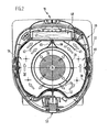
- the inner housing 18 has a lid 20 in a lateral area überfange outlet opening 46, on which a fine filter 48 is arranged, and on the diametrically opposite side of the outlet opening 46 are on Top 14 an operating element for switching on and off it electric motor 36th in the form of an electromechanical switching element 50 and a in the Drawing not shown socket for connecting a power tool arranged.
- the outer wall 30 forms a concavely curved Strömungsleitwand 52, and adjacent thereto, the inner wall 28 a Through opening 54.
- the suction unit 34 With the exception of the passage opening 34 surrounds the inner wall 28, the suction unit 34 completely in the circumferential direction, so that between the suction unit 34 and the inner wall 28, an inner annular space 56 is defined. This is about the passage opening 34 with a outer annular space 58 in fluid communication, in the radial direction of the inner wall 28 and the outer wall 30 is limited and a first semi-annular outlet channel 59 and a second semi-annular outlet channel 60 forms, extending in the circumferential direction between the flow guide 52 and the outlet opening 56 extend.
- the a division of the suction air flow 44 causes, wherein the two flow components each pass through an outlet channel 59 and 60, to subsequently together through the outlet opening 46 and the adjoining Fine filter 48 pass through.
- the outlet channels 59 and 60 each have a free-standing guide wall 62 and 63, the one Parallelization and alignment of the suction air flow in the direction of the Fine filter 48 effect.
- the distance of the guide walls 62 and 63 to the inner wall 28 is about 20% larger than the distance that the guide walls 62 and 63 to the outer wall 30 occupy.
- the outlet opening 46 immediately adjacent end portions of the guide walls 62 and 63, this is clear from Figure 2, concave curved.
- baffles 65 and 66 that of Strömungsleitwand 52 diametrically opposite to the inner wall 58 integrally formed on a common, rounded end edge 67 in one piece connected to each other.
- the cover 20 On the top side, the cover 20 has a receptacle 69 for a cable winding 70 on.
- the receptacle 69 is of a substantially horizontally oriented Supporting wall 72 limited to the one circular, coaxial with the central axis 38th aligned annular wall 73 is formed, from a radially outward pointing projection 74 is covered.
- the annular wall 73 also have an oval shape in plan view.
- the vacuum cleaner 10 is characterized by a particularly low noise during operation of the suction unit 34.
- a particularly low noise during operation of the suction unit 34.
- For this carries the relatively large flow cross-section of the two outlet channels 59 and 60, whose large flow cross-section are ensured can by the diametrical arrangement of the switching element 50 and the outlet opening 46 with fine filter 48.
- In the circumferential direction of the suction unit 34 is virtually the entire space of the upper part 14 for guiding the suction flow 44 available, so that within the outlet channels 59 and 60 a relatively low flow velocity can be ensured can, by which the noise is kept low.
Landscapes
- Engineering & Computer Science (AREA)
- Mechanical Engineering (AREA)
- Nozzles For Electric Vacuum Cleaners (AREA)
- Filters For Electric Vacuum Cleaners (AREA)
- Addition Polymer Or Copolymer, Post-Treatments, Or Chemical Modifications (AREA)
- Catching Or Destruction (AREA)
Abstract
Description
- Figur 1:
- eine vertikale Schnittansicht eines erfindungsgemäßen Staubsaugers;
- Figur 2:
- eine horizontale Schnittansicht längs der Linie 2-2 in Figur 1.
Claims (20)
- Staubsauger mit einem Staubsaugergehäuse, das ein Unterteil und ein auf dieses aufsetzbares Oberteil umfaßt, wobei das Unterteil einen Schmutzsammelbehälter ausbildet und das Oberteil ein elektrisches Saugaggregat mit einem Elektromotor und einer Saugturbine aufnimmt, wobei das Saugaggregat in Umfangsrichtung von zwei halbringförmigen Auslaßkanälen umgeben ist, die in eine gemeinsame Auslaßöffnung einmünden zum Abgeben der vom Saugaggregat angesaugten Saugluft, und wobei seitlich am Oberteil ein Bedienelement zum Ein- und Ausschalten des Elektromotors angeordnet ist, dadurch gekennzeichnet, daß das Bedienelement (50) und die Auslaßöffnung (46) einander diametral gegenüberliegen und zwischen sich das Saugaggregat (34) und die beiden Auslaßkanäle (59, 60) aufnehmen.
- Staubsauger nach Anspruch 1, dadurch gekennzeichnet, daß die Saugturbine (35) und der Elektromotor (36) eine Mittelachse (38) des Oberteiles (14) definierend axial hintereinander angeordnet sind.
- Staubsauger nach Anspruch 1 oder 2, dadurch gekennzeichnet, daß die Saugluft ausgehend von der Saugturbine (35) den Elektromotor (36) durchströmt und anschließend außenseitig in die der Saugturbine (35) zugewandte Richtung am Elektromotor (36) entlang geführt ist.
- Staubsauger nach einem der voranstehenden Ansprüche, dadurch gekennzeichnet, daß zwischen dem Saugaggregat (34) und dem Bedienelement (50) eine Strömungsleitwand (52) angeordnet ist, wobei mittels der Strömungsleitwand (52) die vom Saugaggregat (34) hervorgerufene Saugluftströmung (44) in zwei Strömungsanteile aufteilbar ist, die jeweils einem Auslaßkanal (59, 60) zuführbar sind.
- Staubsauger nach Anspruch 4, dadurch gekennzeichnet, daß die Strömungsleitwand (52) eine innenseitige Abdeckung des Bedienelementes (50) ausbildet.
- Staubsauger nach Anspruch 4 oder 5, dadurch gekennzeichnet, daß die Strömungsleitwand (52) bezogen auf die Mittelachse (38) des Oberteils (14) konkav gekrümmt ist.
- Staubsauger nach einem der voranstehenden Ansprüche, dadurch gekennzeichnet, daß das Oberteil (14) ein das Saugaggregat (34) umgebendes Innengehäuse (18) aufweist sowie einen das Innengehäuse überdeckenden Deckel (20).
- Staubsauger nach Anspruch 7, dadurch gekennzeichnet, daß das Innengehäuse (18) in das Unterteil (12) einsteckbar ist.
- Staubsauger nach Anspruch 7 oder 8, dadurch gekennzeichnet, daß das Innengehäuse (18) zweiteilig ausgestaltet ist und ein erstes Innengehäuseteil (22) sowie ein zweites Innengehäuseteil (24) aufweist.
- Staubsauger nach Anspruch 7, 8 oder 9, dadurch gekennzeichnet, daß das Innengehäuse (18) eine das Saugaggregat (34) in Umfangsrichtung umgebende Innenwand (28) sowie eine in radialem Abstand zu dieser verlaufende Außenwand (30) aufweist, zwischen denen die Auslaßkanäle (59, 60) verlaufen.
- Staubsauger nach Anspruch 10, dadurch gekennzeichnet, daß die Innenwand (28) und die Außenwand (30) an eine in das Unterteil (12) eintauchende Bodenwand (26) des Innengehäuses (18) angeformt sind.
- Staubsauger nach Anspruch 10 oder 11, dadurch gekennzeichnet, daß das Innengehäuse (18) eine das Saugaggregat (34) und die Auslaßkanäle (59, 60) überdeckende und auf die Innen- und die Außenwand (28, 30) aufsetzbare Haube (22) umfaßt.
- Staubsauger nach einem der voranstehenden Ansprüche, dadurch gekennzeichnet, daß an der Auslaßöffnung (46) ein Filterelement (48) angeordnet ist.
- Staubsauger nach Anspruch 13, dadurch gekennzeichnet, daß die Auslaßkanäle (59, 60) in ihrem dem Filterelement (48) benachbarten Endbereich jeweils zumindest eine Führungswand (62, 63) zur Parallelisierung und Ausrichtung der Saugluftströmung (44) in Richtung auf das Filterelement (48) aufweisen.
- Staubsauger nach Anspruch 14, dadurch gekennzeichnet, daß jeweils zumindest eine Führungswand (62, 63) freistehend im jeweiligen Endbereich der Auslaßkanäle (59, 60) angeordnet ist.
- Staubsauger nach Anspruch 14 oder 15, dadurch gekennzeichnet, daß die Führungswände (62, 63) gekrümmt sind.
- Staubsauger nach einem der voranstehenden Ansprüche, dadurch gekennzeichnet, daß zumindest im Bereich der Auslaßöffnung (46) Endkanten (67) der Auslaßkanäle (59, 60) abgerundet sind.
- Staubsauger nach einem der voranstehenden Ansprüche, dadurch gekennzeichnet, daß das Oberteil (14) oberseitig eine Aufnahme (69) für eine Kabelwicklung (70) aufweist.
- Staubsauger nach Anspruch 18, dadurch gekennzeichnet, daß die Aufnahme (69) eine kreisförmige Ringwand (73) umfaßt, die koaxial zur Mittelachse (38) des Oberteils (14) ausgerichtet ist.
- Staubsauger nach Anspruch 18, dadurch gekennzeichnet, daß die Aufnahme (69) eine ovalförmige Ringwand umfaßt.
Priority Applications (1)
| Application Number | Priority Date | Filing Date | Title |
|---|---|---|---|
| PL05001761T PL1559359T3 (pl) | 2004-01-30 | 2005-01-28 | Odkurzacz |
Applications Claiming Priority (2)
| Application Number | Priority Date | Filing Date | Title |
|---|---|---|---|
| DE102004005500A DE102004005500A1 (de) | 2004-01-30 | 2004-01-30 | Staubsauger |
| DE102004005500 | 2004-01-30 |
Publications (3)
| Publication Number | Publication Date |
|---|---|
| EP1559359A2 true EP1559359A2 (de) | 2005-08-03 |
| EP1559359A3 EP1559359A3 (de) | 2006-04-05 |
| EP1559359B1 EP1559359B1 (de) | 2010-03-10 |
Family
ID=34638841
Family Applications (1)
| Application Number | Title | Priority Date | Filing Date |
|---|---|---|---|
| EP05001761A Expired - Lifetime EP1559359B1 (de) | 2004-01-30 | 2005-01-28 | Staubsauger |
Country Status (5)
| Country | Link |
|---|---|
| EP (1) | EP1559359B1 (de) |
| AT (1) | ATE460106T1 (de) |
| DE (2) | DE102004005500A1 (de) |
| DK (1) | DK1559359T3 (de) |
| PL (1) | PL1559359T3 (de) |
Cited By (7)
| Publication number | Priority date | Publication date | Assignee | Title |
|---|---|---|---|---|
| WO2007025115A3 (en) * | 2005-08-25 | 2007-06-14 | Shop Vac Corp | Portable, compact pneumatic suction cleaner with means for low noise operation |
| WO2018068850A1 (de) | 2016-10-12 | 2018-04-19 | Alfred Kärcher Gmbh & Co. Kg | Reinigungsgerät und verfahren zur herstellung eines reinigungsgeräts |
| DE102018108559A1 (de) | 2018-04-11 | 2019-10-17 | Alfred Kärcher SE & Co. KG | Reinigungsgerät |
| WO2019227216A1 (en) * | 2018-05-30 | 2019-12-05 | Omachron Intellectual Property Inc. | Surface cleaning apparatus |
| EP3673780A1 (de) * | 2018-12-29 | 2020-07-01 | Jiangsu Midea Cleaning Appliances Co., Ltd. | Motorabdeckung für staubsauger, motormodul eines staubsaugers und staubsauger |
| US10827889B2 (en) | 2018-05-30 | 2020-11-10 | Omachron Intellectual Property Inc. | Surface cleaning apparatus |
| US11116369B2 (en) | 2016-04-27 | 2021-09-14 | Diversey, Inc. | Vacuum cleaner |
Families Citing this family (3)
| Publication number | Priority date | Publication date | Assignee | Title |
|---|---|---|---|---|
| DE102010043581A1 (de) | 2010-11-08 | 2012-05-10 | Hilti Aktiengesellschaft | Staubsauger mit einer Kabelhalteeinrichtung |
| DE202011051991U1 (de) | 2011-11-16 | 2011-11-28 | G. Staehle Gmbh U. Co. Kg | Reinigungsgerät, insbesondere Staubsauger |
| DE102024113322A1 (de) * | 2024-05-13 | 2025-11-13 | Alfred Kärcher SE & Co. KG | Saugreinigungsgerät |
Family Cites Families (5)
| Publication number | Priority date | Publication date | Assignee | Title |
|---|---|---|---|---|
| DE3225258C2 (de) * | 1982-07-06 | 1985-11-28 | Guido Oberdorfer Wap-Maschinen, 7919 Bellenberg | Schmutzsauger |
| US4435877A (en) * | 1982-09-30 | 1984-03-13 | Shop-Vac Corporation | Noise reducing means for vacuum cleaner |
| US4655694A (en) * | 1985-08-01 | 1987-04-07 | Shop-Vac Corporation | Housing assembly for motor/fan means of a wet/dry vacuum cleaner |
| DE4429116A1 (de) * | 1994-03-25 | 1995-09-28 | Hans Dietrich | Kabelaufwickelvorrichtung und Staubsauger mit einer solchen Kabelaufwickelvorrichtung |
| KR970009718A (ko) * | 1995-08-31 | 1997-03-27 | 배순훈 | 진공 청소기의 배기 유로를 길게한 흡음방 |
-
2004
- 2004-01-30 DE DE102004005500A patent/DE102004005500A1/de not_active Withdrawn
-
2005
- 2005-01-28 DE DE502005009164T patent/DE502005009164D1/de not_active Expired - Lifetime
- 2005-01-28 DK DK05001761.5T patent/DK1559359T3/da active
- 2005-01-28 EP EP05001761A patent/EP1559359B1/de not_active Expired - Lifetime
- 2005-01-28 AT AT05001761T patent/ATE460106T1/de not_active IP Right Cessation
- 2005-01-28 PL PL05001761T patent/PL1559359T3/pl unknown
Cited By (17)
| Publication number | Priority date | Publication date | Assignee | Title |
|---|---|---|---|---|
| US7721384B2 (en) | 2005-08-25 | 2010-05-25 | Shop-Vac Corporation | Pneumatic cleaner |
| CN101237806B (zh) * | 2005-08-25 | 2011-05-18 | 肖普瓦克公司 | 带有用于低噪音操作装置的便携式紧凑气动吸入清洁器 |
| WO2007025115A3 (en) * | 2005-08-25 | 2007-06-14 | Shop Vac Corp | Portable, compact pneumatic suction cleaner with means for low noise operation |
| US11116369B2 (en) | 2016-04-27 | 2021-09-14 | Diversey, Inc. | Vacuum cleaner |
| US11937759B2 (en) | 2016-04-27 | 2024-03-26 | Diversey Switzerland Services Gmbh | Vacuum cleaner |
| US11452412B2 (en) | 2016-04-27 | 2022-09-27 | Diversey, Inc. | Vacuum cleaner |
| CN109843134A (zh) * | 2016-10-12 | 2019-06-04 | 阿尔弗雷德·卡赫欧洲两合公司 | 清洁设备和用于制造清洁设备的方法 |
| WO2018068850A1 (de) | 2016-10-12 | 2018-04-19 | Alfred Kärcher Gmbh & Co. Kg | Reinigungsgerät und verfahren zur herstellung eines reinigungsgeräts |
| WO2019197452A1 (de) | 2018-04-11 | 2019-10-17 | Alfred Kärcher SE & Co. KG | Reinigungsgerät |
| DE102018108559A1 (de) | 2018-04-11 | 2019-10-17 | Alfred Kärcher SE & Co. KG | Reinigungsgerät |
| WO2019227216A1 (en) * | 2018-05-30 | 2019-12-05 | Omachron Intellectual Property Inc. | Surface cleaning apparatus |
| US10827889B2 (en) | 2018-05-30 | 2020-11-10 | Omachron Intellectual Property Inc. | Surface cleaning apparatus |
| US10932634B2 (en) | 2018-05-30 | 2021-03-02 | Omachron Intellectual Property Inc. | Surface cleaning apparatus |
| GB2587728A (en) * | 2018-05-30 | 2021-04-07 | Omachron Intellectual Property Inc | Surface cleaning apparatus |
| GB2587728B (en) * | 2018-05-30 | 2022-08-24 | Omachron Intellectual Property Inc | Surface cleaning apparatus |
| US11744421B2 (en) | 2018-05-30 | 2023-09-05 | Omachron Intellectual Property Inc. | Surface cleaning apparatus |
| EP3673780A1 (de) * | 2018-12-29 | 2020-07-01 | Jiangsu Midea Cleaning Appliances Co., Ltd. | Motorabdeckung für staubsauger, motormodul eines staubsaugers und staubsauger |
Also Published As
| Publication number | Publication date |
|---|---|
| PL1559359T3 (pl) | 2010-08-31 |
| DK1559359T3 (da) | 2010-05-17 |
| EP1559359A3 (de) | 2006-04-05 |
| DE502005009164D1 (de) | 2010-04-22 |
| EP1559359B1 (de) | 2010-03-10 |
| DE102004005500A1 (de) | 2005-08-18 |
| ATE460106T1 (de) | 2010-03-15 |
Similar Documents
| Publication | Publication Date | Title |
|---|---|---|
| DE602006000726T2 (de) | Wirbelstaubtrennvorrichung | |
| DE60015304T2 (de) | Luftzufuhrmittel für einen zyklonenabscheider und staubsauger mit demselben | |
| DE10258782B4 (de) | Staubsammelvorrichtung vom Wirbelungstyp für einen Staubsauger | |
| DE10200673B4 (de) | Kraftfahrzeug-Luftfilter | |
| DE112017004196T5 (de) | Staubsammelvorrichtung und diese aufweisender Staubsauger | |
| EP2002773B1 (de) | Staubsauger | |
| DE2455118A1 (de) | Luftreiniger und verfahren zum reinigen von luft | |
| DE10124216A1 (de) | Staubsauger im Hochformat mit einer Staubauffangvorrichtung vom Zyklontyp | |
| WO2008019960A1 (de) | Vorrichtung zur abscheidung von flüssigkeiten aus gasen | |
| DE2750967B1 (de) | Vorrichtung zum Verbinden eines Antriebsmotors und einer Pumpe | |
| EP1559359A2 (de) | Staubsauger | |
| DE102011009741B4 (de) | Zentrifugalabscheider mit Partikelleitrinne | |
| EP1364696B1 (de) | Vorrichtung zur Reinigung eines Gasstromes | |
| EP1685784B1 (de) | Sauggerät | |
| DE102010006556B4 (de) | Luftfilter eines Verbrennungsmotors | |
| DE10045178A1 (de) | Filterelement | |
| EP1124056A2 (de) | Filtereinrichtung für Kraftstoffe | |
| EP2320780A1 (de) | Staubsauger | |
| DE102004030350A1 (de) | Staubsauger | |
| EP2330958B1 (de) | Staubsauger | |
| EP2320783B1 (de) | Staubsauger | |
| EP2130577B1 (de) | Luftaufbereitungsvorrichtung, insbesondere einer Luftdruckbremsanlage mit einem Abscheider für flüssige Fluide | |
| DE102017210322A1 (de) | Abscheidevorrichtung | |
| DE102017220700A1 (de) | Fliehkraftabscheider mit verringerter Bauhöhe | |
| DE102017210325A1 (de) | Abscheidevorrichtung |
Legal Events
| Date | Code | Title | Description |
|---|---|---|---|
| PUAI | Public reference made under article 153(3) epc to a published international application that has entered the european phase |
Free format text: ORIGINAL CODE: 0009012 |
|
| AK | Designated contracting states |
Kind code of ref document: A2 Designated state(s): AT BE BG CH CY CZ DE DK EE ES FI FR GB GR HU IE IS IT LI LT LU MC NL PL PT RO SE SI SK TR |
|
| AX | Request for extension of the european patent |
Extension state: AL BA HR LV MK YU |
|
| PUAL | Search report despatched |
Free format text: ORIGINAL CODE: 0009013 |
|
| AK | Designated contracting states |
Kind code of ref document: A3 Designated state(s): AT BE BG CH CY CZ DE DK EE ES FI FR GB GR HU IE IS IT LI LT LU MC NL PL PT RO SE SI SK TR |
|
| AX | Request for extension of the european patent |
Extension state: AL BA HR LV MK YU |
|
| 17P | Request for examination filed |
Effective date: 20060809 |
|
| AKX | Designation fees paid |
Designated state(s): AT BE BG CH CY CZ DE DK EE ES FI FR GB GR HU IE IS IT LI LT LU MC NL PL PT RO SE SI SK TR |
|
| RAP1 | Party data changed (applicant data changed or rights of an application transferred) |
Owner name: ALFRED KAERCHER GMBH & CO. KG |
|
| GRAP | Despatch of communication of intention to grant a patent |
Free format text: ORIGINAL CODE: EPIDOSNIGR1 |
|
| GRAS | Grant fee paid |
Free format text: ORIGINAL CODE: EPIDOSNIGR3 |
|
| GRAA | (expected) grant |
Free format text: ORIGINAL CODE: 0009210 |
|
| AK | Designated contracting states |
Kind code of ref document: B1 Designated state(s): AT BE BG CH CY CZ DE DK EE ES FI FR GB GR HU IE IS IT LI LT LU MC NL PL PT RO SE SI SK TR |
|
| REG | Reference to a national code |
Ref country code: GB Ref legal event code: FG4D Free format text: NOT ENGLISH |
|
| REG | Reference to a national code |
Ref country code: CH Ref legal event code: NV Representative=s name: ISLER & PEDRAZZINI AG Ref country code: CH Ref legal event code: EP |
|
| REG | Reference to a national code |
Ref country code: IE Ref legal event code: FG4D |
|
| REG | Reference to a national code |
Ref country code: RO Ref legal event code: EPE |
|
| REF | Corresponds to: |
Ref document number: 502005009164 Country of ref document: DE Date of ref document: 20100422 Kind code of ref document: P |
|
| REG | Reference to a national code |
Ref country code: DK Ref legal event code: T3 |
|
| REG | Reference to a national code |
Ref country code: NL Ref legal event code: VDEP Effective date: 20100310 |
|
| PG25 | Lapsed in a contracting state [announced via postgrant information from national office to epo] |
Ref country code: LT Free format text: LAPSE BECAUSE OF FAILURE TO SUBMIT A TRANSLATION OF THE DESCRIPTION OR TO PAY THE FEE WITHIN THE PRESCRIBED TIME-LIMIT Effective date: 20100310 |
|
| LTIE | Lt: invalidation of european patent or patent extension |
Effective date: 20100310 |
|
| PG25 | Lapsed in a contracting state [announced via postgrant information from national office to epo] |
Ref country code: SI Free format text: LAPSE BECAUSE OF FAILURE TO SUBMIT A TRANSLATION OF THE DESCRIPTION OR TO PAY THE FEE WITHIN THE PRESCRIBED TIME-LIMIT Effective date: 20100310 Ref country code: FI Free format text: LAPSE BECAUSE OF FAILURE TO SUBMIT A TRANSLATION OF THE DESCRIPTION OR TO PAY THE FEE WITHIN THE PRESCRIBED TIME-LIMIT Effective date: 20100310 |
|
| REG | Reference to a national code |
Ref country code: PL Ref legal event code: T3 |
|
| REG | Reference to a national code |
Ref country code: IE Ref legal event code: FD4D |
|
| REG | Reference to a national code |
Ref country code: HU Ref legal event code: AG4A Ref document number: E008192 Country of ref document: HU |
|
| PG25 | Lapsed in a contracting state [announced via postgrant information from national office to epo] |
Ref country code: SE Free format text: LAPSE BECAUSE OF FAILURE TO SUBMIT A TRANSLATION OF THE DESCRIPTION OR TO PAY THE FEE WITHIN THE PRESCRIBED TIME-LIMIT Effective date: 20100310 Ref country code: NL Free format text: LAPSE BECAUSE OF FAILURE TO SUBMIT A TRANSLATION OF THE DESCRIPTION OR TO PAY THE FEE WITHIN THE PRESCRIBED TIME-LIMIT Effective date: 20100310 Ref country code: GR Free format text: LAPSE BECAUSE OF FAILURE TO SUBMIT A TRANSLATION OF THE DESCRIPTION OR TO PAY THE FEE WITHIN THE PRESCRIBED TIME-LIMIT Effective date: 20100611 Ref country code: ES Free format text: LAPSE BECAUSE OF FAILURE TO SUBMIT A TRANSLATION OF THE DESCRIPTION OR TO PAY THE FEE WITHIN THE PRESCRIBED TIME-LIMIT Effective date: 20100621 Ref country code: EE Free format text: LAPSE BECAUSE OF FAILURE TO SUBMIT A TRANSLATION OF THE DESCRIPTION OR TO PAY THE FEE WITHIN THE PRESCRIBED TIME-LIMIT Effective date: 20100310 Ref country code: CY Free format text: LAPSE BECAUSE OF FAILURE TO SUBMIT A TRANSLATION OF THE DESCRIPTION OR TO PAY THE FEE WITHIN THE PRESCRIBED TIME-LIMIT Effective date: 20100310 |
|
| PG25 | Lapsed in a contracting state [announced via postgrant information from national office to epo] |
Ref country code: SK Free format text: LAPSE BECAUSE OF FAILURE TO SUBMIT A TRANSLATION OF THE DESCRIPTION OR TO PAY THE FEE WITHIN THE PRESCRIBED TIME-LIMIT Effective date: 20100310 Ref country code: IS Free format text: LAPSE BECAUSE OF FAILURE TO SUBMIT A TRANSLATION OF THE DESCRIPTION OR TO PAY THE FEE WITHIN THE PRESCRIBED TIME-LIMIT Effective date: 20100710 Ref country code: CZ Free format text: LAPSE BECAUSE OF FAILURE TO SUBMIT A TRANSLATION OF THE DESCRIPTION OR TO PAY THE FEE WITHIN THE PRESCRIBED TIME-LIMIT Effective date: 20100310 Ref country code: BG Free format text: LAPSE BECAUSE OF FAILURE TO SUBMIT A TRANSLATION OF THE DESCRIPTION OR TO PAY THE FEE WITHIN THE PRESCRIBED TIME-LIMIT Effective date: 20100610 |
|
| PLBE | No opposition filed within time limit |
Free format text: ORIGINAL CODE: 0009261 |
|
| STAA | Information on the status of an ep patent application or granted ep patent |
Free format text: STATUS: NO OPPOSITION FILED WITHIN TIME LIMIT |
|
| PG25 | Lapsed in a contracting state [announced via postgrant information from national office to epo] |
Ref country code: PT Free format text: LAPSE BECAUSE OF FAILURE TO SUBMIT A TRANSLATION OF THE DESCRIPTION OR TO PAY THE FEE WITHIN THE PRESCRIBED TIME-LIMIT Effective date: 20100712 Ref country code: IE Free format text: LAPSE BECAUSE OF FAILURE TO SUBMIT A TRANSLATION OF THE DESCRIPTION OR TO PAY THE FEE WITHIN THE PRESCRIBED TIME-LIMIT Effective date: 20100310 |
|
| 26N | No opposition filed |
Effective date: 20101213 |
|
| BERE | Be: lapsed |
Owner name: ALFRED KARCHER G.M.B.H. & CO. KG Effective date: 20110131 |
|
| PG25 | Lapsed in a contracting state [announced via postgrant information from national office to epo] |
Ref country code: MC Free format text: LAPSE BECAUSE OF NON-PAYMENT OF DUE FEES Effective date: 20110131 |
|
| PG25 | Lapsed in a contracting state [announced via postgrant information from national office to epo] |
Ref country code: BE Free format text: LAPSE BECAUSE OF NON-PAYMENT OF DUE FEES Effective date: 20110131 |
|
| REG | Reference to a national code |
Ref country code: AT Ref legal event code: MM01 Ref document number: 460106 Country of ref document: AT Kind code of ref document: T Effective date: 20110128 |
|
| PG25 | Lapsed in a contracting state [announced via postgrant information from national office to epo] |
Ref country code: AT Free format text: LAPSE BECAUSE OF NON-PAYMENT OF DUE FEES Effective date: 20110128 |
|
| PG25 | Lapsed in a contracting state [announced via postgrant information from national office to epo] |
Ref country code: LU Free format text: LAPSE BECAUSE OF NON-PAYMENT OF DUE FEES Effective date: 20110128 |
|
| REG | Reference to a national code |
Ref country code: DE Ref legal event code: R082 Ref document number: 502005009164 Country of ref document: DE Representative=s name: HOEGER, STELLRECHT & PARTNER PATENTANWAELTE MB, DE |
|
| REG | Reference to a national code |
Ref country code: FR Ref legal event code: PLFP Year of fee payment: 12 |
|
| REG | Reference to a national code |
Ref country code: FR Ref legal event code: PLFP Year of fee payment: 13 |
|
| REG | Reference to a national code |
Ref country code: FR Ref legal event code: PLFP Year of fee payment: 14 |
|
| REG | Reference to a national code |
Ref country code: DE Ref legal event code: R082 Ref document number: 502005009164 Country of ref document: DE Representative=s name: HOEGER, STELLRECHT & PARTNER PATENTANWAELTE MB, DE Ref country code: DE Ref legal event code: R081 Ref document number: 502005009164 Country of ref document: DE Owner name: ALFRED KAERCHER SE & CO. KG, DE Free format text: FORMER OWNER: ALFRED KAERCHER GMBH & CO. KG, 71364 WINNENDEN, DE |
|
| PGFP | Annual fee paid to national office [announced via postgrant information from national office to epo] |
Ref country code: IE Payment date: 20181227 Year of fee payment: 12 |
|
| PGFP | Annual fee paid to national office [announced via postgrant information from national office to epo] |
Ref country code: FR Payment date: 20181213 Year of fee payment: 15 |
|
| REG | Reference to a national code |
Ref country code: DE Ref legal event code: R082 Ref document number: 502005009164 Country of ref document: DE Representative=s name: HOEGER, STELLRECHT & PARTNER PATENTANWAELTE MB, DE |
|
| PGFP | Annual fee paid to national office [announced via postgrant information from national office to epo] |
Ref country code: RO Payment date: 20191230 Year of fee payment: 16 |
|
| PGFP | Annual fee paid to national office [announced via postgrant information from national office to epo] |
Ref country code: DK Payment date: 20200110 Year of fee payment: 16 Ref country code: GB Payment date: 20200115 Year of fee payment: 16 |
|
| PGFP | Annual fee paid to national office [announced via postgrant information from national office to epo] |
Ref country code: CH Payment date: 20200116 Year of fee payment: 16 |
|
| PGFP | Annual fee paid to national office [announced via postgrant information from national office to epo] |
Ref country code: TR Payment date: 20200128 Year of fee payment: 16 |
|
| PG25 | Lapsed in a contracting state [announced via postgrant information from national office to epo] |
Ref country code: FR Free format text: LAPSE BECAUSE OF NON-PAYMENT OF DUE FEES Effective date: 20200131 |
|
| PG25 | Lapsed in a contracting state [announced via postgrant information from national office to epo] |
Ref country code: HU Free format text: LAPSE BECAUSE OF NON-PAYMENT OF DUE FEES Effective date: 20200129 |
|
| PG25 | Lapsed in a contracting state [announced via postgrant information from national office to epo] |
Ref country code: IT Free format text: LAPSE BECAUSE OF NON-PAYMENT OF DUE FEES Effective date: 20200128 |
|
| PGFP | Annual fee paid to national office [announced via postgrant information from national office to epo] |
Ref country code: DE Payment date: 20210128 Year of fee payment: 17 |
|
| REG | Reference to a national code |
Ref country code: DK Ref legal event code: EBP Effective date: 20210131 |
|
| PG25 | Lapsed in a contracting state [announced via postgrant information from national office to epo] |
Ref country code: PL Free format text: LAPSE BECAUSE OF NON-PAYMENT OF DUE FEES Effective date: 20200128 |
|
| REG | Reference to a national code |
Ref country code: CH Ref legal event code: PL |
|
| GBPC | Gb: european patent ceased through non-payment of renewal fee |
Effective date: 20210128 |
|
| PG25 | Lapsed in a contracting state [announced via postgrant information from national office to epo] |
Ref country code: RO Free format text: LAPSE BECAUSE OF NON-PAYMENT OF DUE FEES Effective date: 20210128 Ref country code: LI Free format text: LAPSE BECAUSE OF NON-PAYMENT OF DUE FEES Effective date: 20210131 Ref country code: CH Free format text: LAPSE BECAUSE OF NON-PAYMENT OF DUE FEES Effective date: 20210131 Ref country code: GB Free format text: LAPSE BECAUSE OF NON-PAYMENT OF DUE FEES Effective date: 20210128 |
|
| PG25 | Lapsed in a contracting state [announced via postgrant information from national office to epo] |
Ref country code: DK Free format text: LAPSE BECAUSE OF NON-PAYMENT OF DUE FEES Effective date: 20210131 |
|
| REG | Reference to a national code |
Ref country code: DE Ref legal event code: R119 Ref document number: 502005009164 Country of ref document: DE |
|
| PG25 | Lapsed in a contracting state [announced via postgrant information from national office to epo] |
Ref country code: DE Free format text: LAPSE BECAUSE OF NON-PAYMENT OF DUE FEES Effective date: 20220802 |